Embed Size (px)
Citation preview
The SWIFT BAT Software Guide
Version 6.3
30 Jul 2007
C. B. Markwardt,
S. D. Barthelmy, J. C. Cummings,
D. Hullinger, H. A. Krimm, A. Parsons,
(NASA/GSFC — BAT Instrument Team)
Contents
1 Introduction 1
1.1 Scope . . . . . . . . . . . . . . . . . . . . . . . . . . . . . . . . . . . . . . . . . . . . 1
1.2 The Basic Scheme . . . . . . . . . . . . . . . . . . . . . . . . . . . . . . . . . . . . . 1
1.3 Organization of this Guide . . . . . . . . . . . . . . . . . . . . . . . . . . . . . . . . . 1
1.4 New releases and Updates . . . . . . . . . . . . . . . . . . . . . . . . . . . . . . . . . 2
1.5 Revision History . . . . . . . . . . . . . . . . . . . . . . . . . . . . . . . . . . . . . . 2
2 BAT Instrument 3
2.1 Swift Overview . . . . . . . . . . . . . . . . . . . . . . . . . . . . . . . . . . . . . . . 3
2.2 Instrument Overview . . . . . . . . . . . . . . . . . . . . . . . . . . . . . . . . . . . . 3
2.3 The Swift Spacecraft . . . . . . . . . . . . . . . . . . . . . . . . . . . . . . . . . . . . 3
2.4 The BAT Instrument . . . . . . . . . . . . . . . . . . . . . . . . . . . . . . . . . . . . 4
2.4.1 Technical Description . . . . . . . . . . . . . . . . . . . . . . . . . . . . . . . 4
2.4.2 Instrument Operations . . . . . . . . . . . . . . . . . . . . . . . . . . . . . . . 8
3 BAT Operating Modes and Data Types 11
3.1 Introduction . . . . . . . . . . . . . . . . . . . . . . . . . . . . . . . . . . . . . . . . . 11
3.2 GRB Products and Response . . . . . . . . . . . . . . . . . . . . . . . . . . . . . . . 11
3.2.1 Important Notes About Trigger Times . . . . . . . . . . . . . . . . . . . . . . 13
3.2.2 Description of Standard Products . . . . . . . . . . . . . . . . . . . . . . . . . 13
3.3 Non-GRB Products . . . . . . . . . . . . . . . . . . . . . . . . . . . . . . . . . . . . . 14
3.3.1 Survey Data . . . . . . . . . . . . . . . . . . . . . . . . . . . . . . . . . . . . 15
3.3.2 Rate Data . . . . . . . . . . . . . . . . . . . . . . . . . . . . . . . . . . . . . . 15
3.3.3 Maps . . . . . . . . . . . . . . . . . . . . . . . . . . . . . . . . . . . . . . . . 17
3.3.4 Trend Products . . . . . . . . . . . . . . . . . . . . . . . . . . . . . . . . . . . 17
4 Introduction to BAT Analysis 19
4.1 Introduction . . . . . . . . . . . . . . . . . . . . . . . . . . . . . . . . . . . . . . . . . 19
4.2 Coded Apertures: Basic Concepts . . . . . . . . . . . . . . . . . . . . . . . . . . . . 19
4.3 Coded Aperture Analysis for X-ray Astronomers . . . . . . . . . . . . . . . . . . . . 21
i
ii CONTENTS
4.4 How Sky Fluxes are Reconstructed . . . . . . . . . . . . . . . . . . . . . . . . . . . . 23
4.5 BAT Field of View and Partial Coding . . . . . . . . . . . . . . . . . . . . . . . . . . 23
4.6 BAT Coordinates . . . . . . . . . . . . . . . . . . . . . . . . . . . . . . . . . . . . . . 24
4.7 Definition of BAT Count Units and Corrections . . . . . . . . . . . . . . . . . . . . . 25
4.7.1 Definition of BAT Mask-Weighted Counts . . . . . . . . . . . . . . . . . . . . 25
4.7.2 Converting to a counts per area . . . . . . . . . . . . . . . . . . . . . . . . . . 26
5 BAT Analysis Procedures 27
5.1 Introduction . . . . . . . . . . . . . . . . . . . . . . . . . . . . . . . . . . . . . . . . . 27
5.2 Complete GRB Processing Script . . . . . . . . . . . . . . . . . . . . . . . . . . . . . 28
5.2.1 Introduction . . . . . . . . . . . . . . . . . . . . . . . . . . . . . . . . . . . . 28
5.2.2 Prerequisites . . . . . . . . . . . . . . . . . . . . . . . . . . . . . . . . . . . . 28
5.2.3 Change to Data Directory . . . . . . . . . . . . . . . . . . . . . . . . . . . . . 28
5.2.4 Creating GRB Products Automatically . . . . . . . . . . . . . . . . . . . . . 28
5.2.5 Results . . . . . . . . . . . . . . . . . . . . . . . . . . . . . . . . . . . . . . . 29
5.2.6 When Things Go Wrong . . . . . . . . . . . . . . . . . . . . . . . . . . . . . . 29
5.2.7 Making Your Own Custom Products . . . . . . . . . . . . . . . . . . . . . . . 29
5.2.8 Spectral Fitting . . . . . . . . . . . . . . . . . . . . . . . . . . . . . . . . . . . 30
5.3 Energy Calibration of Events . . . . . . . . . . . . . . . . . . . . . . . . . . . . . . . 30
5.3.1 Reasons to Re-run the Energy Calibration . . . . . . . . . . . . . . . . . . . . 30
5.3.2 Prerequisites . . . . . . . . . . . . . . . . . . . . . . . . . . . . . . . . . . . . 30
5.3.3 Initial Steps . . . . . . . . . . . . . . . . . . . . . . . . . . . . . . . . . . . . . 31
5.3.4 Compute Energy Calibration for BAT Events . . . . . . . . . . . . . . . . . . 31
5.3.5 What to do if no gain/offset map is present . . . . . . . . . . . . . . . . . . . 31
5.4 Making a Detector Quality Map . . . . . . . . . . . . . . . . . . . . . . . . . . . . . 32
5.4.1 Reasons to Create a BAT Quality Map . . . . . . . . . . . . . . . . . . . . . 32
5.4.2 Prerequisites . . . . . . . . . . . . . . . . . . . . . . . . . . . . . . . . . . . . 33
5.4.3 Initial Steps . . . . . . . . . . . . . . . . . . . . . . . . . . . . . . . . . . . . . 33
5.4.4 Create a Detector Plane Image . . . . . . . . . . . . . . . . . . . . . . . . . . 33
5.4.5 Retrieve Known Problematic Detectors . . . . . . . . . . . . . . . . . . . . . 34
5.4.6 Find Noisy Detectors . . . . . . . . . . . . . . . . . . . . . . . . . . . . . . . . 34
5.4.7 Where to Use the Quality Map . . . . . . . . . . . . . . . . . . . . . . . . . . 34
5.4.8 The Difference Between the Enable/Disable Map and the Quality Map . . . . 34
5.4.9 What to do if no detector enable/disable map is present . . . . . . . . . . . . 35
5.5 Mask Weighting (Ray Tracing) . . . . . . . . . . . . . . . . . . . . . . . . . . . . . . 35
5.5.1 Introduction . . . . . . . . . . . . . . . . . . . . . . . . . . . . . . . . . . . . 35
5.5.2 Reasons to Re-run the Mask Weighting . . . . . . . . . . . . . . . . . . . . . 36
5.5.3 Prerequisites . . . . . . . . . . . . . . . . . . . . . . . . . . . . . . . . . . . . 37
CONTENTS iii
5.5.4 Initial Steps . . . . . . . . . . . . . . . . . . . . . . . . . . . . . . . . . . . . . 37
5.5.5 Compute Mask Weights for BAT Events . . . . . . . . . . . . . . . . . . . . . 38
5.6 Light Curve from Event Data . . . . . . . . . . . . . . . . . . . . . . . . . . . . . . . 38
5.6.1 Prerequisites . . . . . . . . . . . . . . . . . . . . . . . . . . . . . . . . . . . . 38
5.6.2 Change into Event Directory . . . . . . . . . . . . . . . . . . . . . . . . . . . 39
5.6.3 Make the light curve . . . . . . . . . . . . . . . . . . . . . . . . . . . . . . . . 39
5.6.4 Plot the Light Curve . . . . . . . . . . . . . . . . . . . . . . . . . . . . . . . . 40
5.6.5 Changing the Energy Binning . . . . . . . . . . . . . . . . . . . . . . . . . . . 40
5.6.6 Changing the time binning . . . . . . . . . . . . . . . . . . . . . . . . . . . . 41
5.6.7 Optional: Making a GTI file . . . . . . . . . . . . . . . . . . . . . . . . . . . 41
5.7 Spectrum and Response Matrix . . . . . . . . . . . . . . . . . . . . . . . . . . . . . . 43
5.7.1 Introduction . . . . . . . . . . . . . . . . . . . . . . . . . . . . . . . . . . . . 43
5.7.2 Prerequisites . . . . . . . . . . . . . . . . . . . . . . . . . . . . . . . . . . . . 43
5.7.3 Change into Event Directory . . . . . . . . . . . . . . . . . . . . . . . . . . . 44
5.7.4 Make the spectrum . . . . . . . . . . . . . . . . . . . . . . . . . . . . . . . . . 44
5.7.5 Apply Corrections to the Spectrum . . . . . . . . . . . . . . . . . . . . . . . . 44
5.7.6 Generate a Response Matrix . . . . . . . . . . . . . . . . . . . . . . . . . . . 45
5.7.7 Important: Spectrum of a Source During a Slew . . . . . . . . . . . . . . . . 45
5.7.8 Analyze Spectrum in XSPEC . . . . . . . . . . . . . . . . . . . . . . . . . . . 45
5.7.9 Choosing Different Energy Binning . . . . . . . . . . . . . . . . . . . . . . . . 46
5.7.10 Do Not Use GRPPHA . . . . . . . . . . . . . . . . . . . . . . . . . . . . . . . 46
5.7.11 Making Multiple Spectra . . . . . . . . . . . . . . . . . . . . . . . . . . . . . 47
5.8 Making BAT Sky Images . . . . . . . . . . . . . . . . . . . . . . . . . . . . . . . . . 47
5.8.1 Introduction . . . . . . . . . . . . . . . . . . . . . . . . . . . . . . . . . . . . 47
5.8.2 Prerequisites . . . . . . . . . . . . . . . . . . . . . . . . . . . . . . . . . . . . 47
5.8.3 Change into Event Directory . . . . . . . . . . . . . . . . . . . . . . . . . . . 48
5.8.4 Make a Detector Plane Image . . . . . . . . . . . . . . . . . . . . . . . . . . . 48
5.8.5 Making a Background Detector Plane Image . . . . . . . . . . . . . . . . . . 49
5.8.6 Making a Sky Image . . . . . . . . . . . . . . . . . . . . . . . . . . . . . . . . 49
5.8.7 Caveats . . . . . . . . . . . . . . . . . . . . . . . . . . . . . . . . . . . . . . . 49
5.8.8 Making a Partial Coding Image . . . . . . . . . . . . . . . . . . . . . . . . . . 50
5.9 Detecting Sources in BAT Images . . . . . . . . . . . . . . . . . . . . . . . . . . . . . 50
5.9.1 Introduction . . . . . . . . . . . . . . . . . . . . . . . . . . . . . . . . . . . . 50
5.9.2 Prerequisites . . . . . . . . . . . . . . . . . . . . . . . . . . . . . . . . . . . . 51
5.9.3 Perform Blind Source Detection . . . . . . . . . . . . . . . . . . . . . . . . . . 51
5.9.4 Finding the Intensities of Known Sources . . . . . . . . . . . . . . . . . . . . 53
5.9.5 Advanced Usage . . . . . . . . . . . . . . . . . . . . . . . . . . . . . . . . . . 54
iv CONTENTS
6 BAT Analysis Issues 55
6.1 Introduction . . . . . . . . . . . . . . . . . . . . . . . . . . . . . . . . . . . . . . . . . 55
6.2 Current Issues . . . . . . . . . . . . . . . . . . . . . . . . . . . . . . . . . . . . . . . . 55
6.2.1 batoccultgti: Fails when checking the field of view only . . . . . . . . . . . . 55
6.2.2 batbinevt: ignores standard 4-channel energy bins . . . . . . . . . . . . . . . 56
6.2.3 batbinevt: DPH rows with fractional exposure are not accounted for properly 56
6.2.4 batcelldetect: newly detected sources may be deleted . . . . . . . . . . . . . . 57
6.2.5 batcelldetect: the correct point spread function is gaussian . . . . . . . . . . 58
6.2.6 Analysis: Passive materials distort the off-axis counts/rates . . . . . . . . . . 58
6.2.7 batfftimage and batmaskwtimg: potentially incorrect derived attitude . . . . 59
6.2.8 Analysis: Earth and Moon Occultation . . . . . . . . . . . . . . . . . . . . . 59
6.3 Old Issues . . . . . . . . . . . . . . . . . . . . . . . . . . . . . . . . . . . . . . . . . . 60
6.3.1 Analysis: Users must apply systematic error vector for spectral fitting . . . . 60
6.3.2 batmaskwtevt: Slewing Raytracing Keywords Potentially Incorrect . . . . . . 61
6.3.3 Analysis: filtering out non-gamma-ray events may improve sensitivity . . . . 62
6.3.4 SDC: BAT data from SDC pipeline has incorrect DATE-OBS/END keywords 62
6.3.5 batoccultmap: incorrect exposure correction . . . . . . . . . . . . . . . . . . . 63
6.3.6 batbinevt: light curves have slightly incorrect energy bins . . . . . . . . . . . 64
6.3.7 Mask tagged light curve systematic flux errors . . . . . . . . . . . . . . . . . 64
6.3.8 XSPEC crashes with segmentation fault with BAT spectra . . . . . . . . . . 65
6.3.9 baterebin: Possible extra rows in EBOUNDS extension of output DPH . . . . 65
6.3.10 batbinevt: Incorrect exposure for survey analysis . . . . . . . . . . . . . . . . 66
6.3.11 CALDB: Incorrect Spectral Response < 20 keV . . . . . . . . . . . . . . . . . 66
6.3.12 CALDB: Incorrect Alignment Matrix . . . . . . . . . . . . . . . . . . . . . . . 66
6.3.13 batbinevt: Incorrect EXPOSURE Keyword . . . . . . . . . . . . . . . . . . . 67
6.3.14 batcelldetect: Incorrect Error Bars . . . . . . . . . . . . . . . . . . . . . . . . 67
6.3.15 batbinevt: Incorrect Handling of float point DPHs . . . . . . . . . . . . . . . 68
6.3.16 batmasktaglc: light curve error bars too small . . . . . . . . . . . . . . . . . . 68
6.3.17 batmaskwtevt/batmaskwtimg: High-Energy Background Contamination . . . 68
A BAT Data Formats 69
A.1 Introduction . . . . . . . . . . . . . . . . . . . . . . . . . . . . . . . . . . . . . . . . . 69
A.2 File Naming Overview . . . . . . . . . . . . . . . . . . . . . . . . . . . . . . . . . . . 69
A.3 Event Files . . . . . . . . . . . . . . . . . . . . . . . . . . . . . . . . . . . . . . . . . 69
A.4 Survey Detector Plane Histograms . . . . . . . . . . . . . . . . . . . . . . . . . . . . 70
A.5 Rate Files . . . . . . . . . . . . . . . . . . . . . . . . . . . . . . . . . . . . . . . . . . 71
A.5.1 One-second Rates . . . . . . . . . . . . . . . . . . . . . . . . . . . . . . . . . 71
A.5.2 Quadrant Rates . . . . . . . . . . . . . . . . . . . . . . . . . . . . . . . . . . . 72
CONTENTS v
A.5.3 64-Millisecond Rates . . . . . . . . . . . . . . . . . . . . . . . . . . . . . . . . 72
A.5.4 Maximum Rates . . . . . . . . . . . . . . . . . . . . . . . . . . . . . . . . . . 72
A.5.5 Mask-tagged Light Curves . . . . . . . . . . . . . . . . . . . . . . . . . . . . . 73
A.5.6 TDRSS GRB Light Curves . . . . . . . . . . . . . . . . . . . . . . . . . . . . 74
A.6 Maps . . . . . . . . . . . . . . . . . . . . . . . . . . . . . . . . . . . . . . . . . . . . . 74
A.6.1 Detector Enable/Disable Map . . . . . . . . . . . . . . . . . . . . . . . . . . . 74
A.6.2 Detector Quality Map . . . . . . . . . . . . . . . . . . . . . . . . . . . . . . . 75
A.6.3 Gain / Offset Map . . . . . . . . . . . . . . . . . . . . . . . . . . . . . . . . . 75
A.6.4 Mask Weight Map . . . . . . . . . . . . . . . . . . . . . . . . . . . . . . . . . 76
A.7 TDRSS Messages . . . . . . . . . . . . . . . . . . . . . . . . . . . . . . . . . . . . . . 76
A.7.1 BAT GRB Alert . . . . . . . . . . . . . . . . . . . . . . . . . . . . . . . . . . 77
A.7.2 GRB Position Message (ACK or NACK) . . . . . . . . . . . . . . . . . . . . 77
A.7.3 FoM and S/C Will/Will Not Observe . . . . . . . . . . . . . . . . . . . . . . 77
A.7.4 BAT Light Curves . . . . . . . . . . . . . . . . . . . . . . . . . . . . . . . . . 78
A.8 Housekeeping Files . . . . . . . . . . . . . . . . . . . . . . . . . . . . . . . . . . . . . 79
A.8.1 Americium Survey DPHs . . . . . . . . . . . . . . . . . . . . . . . . . . . . . 79
A.8.2 Americium Block Spectra . . . . . . . . . . . . . . . . . . . . . . . . . . . . . 79
A.8.3 Calibration Pulser Maps . . . . . . . . . . . . . . . . . . . . . . . . . . . . . . 79
A.8.4 Detector Array Panel (DAP) Housekeeping . . . . . . . . . . . . . . . . . . . 79
A.8.5 BAT Engineering Housekeeping . . . . . . . . . . . . . . . . . . . . . . . . . . 82
A.8.6 DI Commandables . . . . . . . . . . . . . . . . . . . . . . . . . . . . . . . . . 84
A.8.7 Debug Stream . . . . . . . . . . . . . . . . . . . . . . . . . . . . . . . . . . . 84
A.8.8 Trigger Diagnostic Tables . . . . . . . . . . . . . . . . . . . . . . . . . . . . . 84
B BAT FITS Keywords 85
B.1 Introduction . . . . . . . . . . . . . . . . . . . . . . . . . . . . . . . . . . . . . . . . . 85
B.1.1 Keywords Used . . . . . . . . . . . . . . . . . . . . . . . . . . . . . . . . . . . 85
B.1.2 Data Types . . . . . . . . . . . . . . . . . . . . . . . . . . . . . . . . . . . . . 87
C BAT Acronym and Terminology Glossary 89
D BAT Software Tool Reference 93
D.1 BATBINEVT . . . . . . . . . . . . . . . . . . . . . . . . . . . . . . . . . . . . . . . . 94
D.1.1 NAME . . . . . . . . . . . . . . . . . . . . . . . . . . . . . . . . . . . . . . . . 94
D.1.2 USAGE . . . . . . . . . . . . . . . . . . . . . . . . . . . . . . . . . . . . . . . 94
D.1.3 DESCRIPTION . . . . . . . . . . . . . . . . . . . . . . . . . . . . . . . . . . 94
D.1.4 PARAMETERS . . . . . . . . . . . . . . . . . . . . . . . . . . . . . . . . . . 96
D.1.5 EXAMPLES . . . . . . . . . . . . . . . . . . . . . . . . . . . . . . . . . . . . 100
vi CONTENTS
D.1.6 SEE ALSO . . . . . . . . . . . . . . . . . . . . . . . . . . . . . . . . . . . . . 104
D.1.7 LAST MODIFIED . . . . . . . . . . . . . . . . . . . . . . . . . . . . . . . . . 104
D.2 BATCELLDETECT . . . . . . . . . . . . . . . . . . . . . . . . . . . . . . . . . . . . 105
D.2.1 NAME . . . . . . . . . . . . . . . . . . . . . . . . . . . . . . . . . . . . . . . . 105
D.2.2 USAGE . . . . . . . . . . . . . . . . . . . . . . . . . . . . . . . . . . . . . . . 105
D.2.3 DESCRIPTION . . . . . . . . . . . . . . . . . . . . . . . . . . . . . . . . . . 105
D.2.4 CATALOG OUTPUT . . . . . . . . . . . . . . . . . . . . . . . . . . . . . . . 106
D.2.5 DISTORTION CORRECTION . . . . . . . . . . . . . . . . . . . . . . . . . . 109
D.2.6 PARAMETERS . . . . . . . . . . . . . . . . . . . . . . . . . . . . . . . . . . 109
D.2.7 EXAMPLES . . . . . . . . . . . . . . . . . . . . . . . . . . . . . . . . . . . . 114
D.2.8 SEE ALSO . . . . . . . . . . . . . . . . . . . . . . . . . . . . . . . . . . . . . 115
D.2.9 LAST MODIFIED . . . . . . . . . . . . . . . . . . . . . . . . . . . . . . . . . 115
D.3 BATCLEAN . . . . . . . . . . . . . . . . . . . . . . . . . . . . . . . . . . . . . . . . 116
D.3.1 NAME . . . . . . . . . . . . . . . . . . . . . . . . . . . . . . . . . . . . . . . . 116
D.3.2 USAGE . . . . . . . . . . . . . . . . . . . . . . . . . . . . . . . . . . . . . . . 116
D.3.3 DESCRIPTION . . . . . . . . . . . . . . . . . . . . . . . . . . . . . . . . . . 116
D.3.4 PARAMETERS . . . . . . . . . . . . . . . . . . . . . . . . . . . . . . . . . . 117
D.3.5 EXAMPLES . . . . . . . . . . . . . . . . . . . . . . . . . . . . . . . . . . . . 121
D.3.6 BUGS . . . . . . . . . . . . . . . . . . . . . . . . . . . . . . . . . . . . . . . . 122
D.3.7 SEE ALSO . . . . . . . . . . . . . . . . . . . . . . . . . . . . . . . . . . . . . 122
D.3.8 REFERENCES . . . . . . . . . . . . . . . . . . . . . . . . . . . . . . . . . . . 122
D.3.9 LAST MODIFIED . . . . . . . . . . . . . . . . . . . . . . . . . . . . . . . . . 122
D.4 BATDETMASK . . . . . . . . . . . . . . . . . . . . . . . . . . . . . . . . . . . . . . 123
D.4.1 NAME . . . . . . . . . . . . . . . . . . . . . . . . . . . . . . . . . . . . . . . . 123
D.4.2 USAGE . . . . . . . . . . . . . . . . . . . . . . . . . . . . . . . . . . . . . . . 123
D.4.3 DESCRIPTION . . . . . . . . . . . . . . . . . . . . . . . . . . . . . . . . . . 123
D.4.4 PARAMETERS . . . . . . . . . . . . . . . . . . . . . . . . . . . . . . . . . . 123
D.4.5 EXAMPLES . . . . . . . . . . . . . . . . . . . . . . . . . . . . . . . . . . . . 124
D.4.6 SEE ALSO . . . . . . . . . . . . . . . . . . . . . . . . . . . . . . . . . . . . . 124
D.4.7 LAST MODIFIED . . . . . . . . . . . . . . . . . . . . . . . . . . . . . . . . . 124
D.5 BATDRMGEN . . . . . . . . . . . . . . . . . . . . . . . . . . . . . . . . . . . . . . . 125
D.5.1 NAME . . . . . . . . . . . . . . . . . . . . . . . . . . . . . . . . . . . . . . . . 125
D.5.2 USAGE . . . . . . . . . . . . . . . . . . . . . . . . . . . . . . . . . . . . . . . 125
D.5.3 DESCRIPTION . . . . . . . . . . . . . . . . . . . . . . . . . . . . . . . . . . 125
D.5.4 THEORY of OPERATION . . . . . . . . . . . . . . . . . . . . . . . . . . . . 126
D.5.5 PARAMETERS . . . . . . . . . . . . . . . . . . . . . . . . . . . . . . . . . . 126
D.5.6 EXAMPLES . . . . . . . . . . . . . . . . . . . . . . . . . . . . . . . . . . . . 129
CONTENTS vii
D.5.7 SEE ALSO . . . . . . . . . . . . . . . . . . . . . . . . . . . . . . . . . . . . . 129
D.5.8 LAST MODIFIED . . . . . . . . . . . . . . . . . . . . . . . . . . . . . . . . . 129
D.6 BATECONVERT . . . . . . . . . . . . . . . . . . . . . . . . . . . . . . . . . . . . . . 130
D.6.1 NAME . . . . . . . . . . . . . . . . . . . . . . . . . . . . . . . . . . . . . . . . 130
D.6.2 USAGE . . . . . . . . . . . . . . . . . . . . . . . . . . . . . . . . . . . . . . . 130
D.6.3 DESCRIPTION . . . . . . . . . . . . . . . . . . . . . . . . . . . . . . . . . . 130
D.6.4 PARAMETERS . . . . . . . . . . . . . . . . . . . . . . . . . . . . . . . . . . 130
D.6.5 EXAMPLES . . . . . . . . . . . . . . . . . . . . . . . . . . . . . . . . . . . . 132
D.6.6 SEE ALSO . . . . . . . . . . . . . . . . . . . . . . . . . . . . . . . . . . . . . 133
D.6.7 LAST MODIFIED . . . . . . . . . . . . . . . . . . . . . . . . . . . . . . . . . 133
D.7 BATEREBIN . . . . . . . . . . . . . . . . . . . . . . . . . . . . . . . . . . . . . . . . 134
D.7.1 NAME . . . . . . . . . . . . . . . . . . . . . . . . . . . . . . . . . . . . . . . . 134
D.7.2 USAGE . . . . . . . . . . . . . . . . . . . . . . . . . . . . . . . . . . . . . . . 134
D.7.3 DESCRIPTION . . . . . . . . . . . . . . . . . . . . . . . . . . . . . . . . . . 134
D.7.4 PARAMETERS . . . . . . . . . . . . . . . . . . . . . . . . . . . . . . . . . . 134
D.7.5 EXAMPLES . . . . . . . . . . . . . . . . . . . . . . . . . . . . . . . . . . . . 136
D.7.6 SEE ALSO . . . . . . . . . . . . . . . . . . . . . . . . . . . . . . . . . . . . . 136
D.7.7 LAST MODIFIED . . . . . . . . . . . . . . . . . . . . . . . . . . . . . . . . . 136
D.8 BATFFTIMAGE . . . . . . . . . . . . . . . . . . . . . . . . . . . . . . . . . . . . . . 137
D.8.1 NAME . . . . . . . . . . . . . . . . . . . . . . . . . . . . . . . . . . . . . . . . 137
D.8.2 USAGE . . . . . . . . . . . . . . . . . . . . . . . . . . . . . . . . . . . . . . . 137
D.8.3 DESCRIPTION . . . . . . . . . . . . . . . . . . . . . . . . . . . . . . . . . . 137
D.8.4 PARAMETERS . . . . . . . . . . . . . . . . . . . . . . . . . . . . . . . . . . 138
D.8.5 EXAMPLES . . . . . . . . . . . . . . . . . . . . . . . . . . . . . . . . . . . . 141
D.8.6 REFERENCES . . . . . . . . . . . . . . . . . . . . . . . . . . . . . . . . . . . 141
D.8.7 SEE ALSO . . . . . . . . . . . . . . . . . . . . . . . . . . . . . . . . . . . . . 141
D.8.8 LAST MODIFIED . . . . . . . . . . . . . . . . . . . . . . . . . . . . . . . . . 142
D.9 BATGLOBALGTI . . . . . . . . . . . . . . . . . . . . . . . . . . . . . . . . . . . . . 143
D.9.1 NAME . . . . . . . . . . . . . . . . . . . . . . . . . . . . . . . . . . . . . . . . 143
D.9.2 USAGE . . . . . . . . . . . . . . . . . . . . . . . . . . . . . . . . . . . . . . . 143
D.9.3 DESCRIPTION . . . . . . . . . . . . . . . . . . . . . . . . . . . . . . . . . . 143
D.9.4 PARAMETERS . . . . . . . . . . . . . . . . . . . . . . . . . . . . . . . . . . 143
D.9.5 EXAMPLES . . . . . . . . . . . . . . . . . . . . . . . . . . . . . . . . . . . . 144
D.9.6 SEE ALSO . . . . . . . . . . . . . . . . . . . . . . . . . . . . . . . . . . . . . 144
D.9.7 LAST MODIFIED . . . . . . . . . . . . . . . . . . . . . . . . . . . . . . . . . 144
D.10 BATGRBPRODUCT . . . . . . . . . . . . . . . . . . . . . . . . . . . . . . . . . . . 145
D.10.1 NAME . . . . . . . . . . . . . . . . . . . . . . . . . . . . . . . . . . . . . . . . 145
viii CONTENTS
D.10.2 USAGE . . . . . . . . . . . . . . . . . . . . . . . . . . . . . . . . . . . . . . . 145
D.10.3 DESCRIPTION . . . . . . . . . . . . . . . . . . . . . . . . . . . . . . . . . . 145
D.10.4 SUMMARY OUTPUTS . . . . . . . . . . . . . . . . . . . . . . . . . . . . . . 146
D.10.5 OUTPUT DIRECTORIES . . . . . . . . . . . . . . . . . . . . . . . . . . . . 146
D.10.6 ERRORS . . . . . . . . . . . . . . . . . . . . . . . . . . . . . . . . . . . . . . 147
D.10.7 PARAMETERS . . . . . . . . . . . . . . . . . . . . . . . . . . . . . . . . . . 147
D.10.8 EXAMPLES . . . . . . . . . . . . . . . . . . . . . . . . . . . . . . . . . . . . 148
D.10.9 SEE ALSO . . . . . . . . . . . . . . . . . . . . . . . . . . . . . . . . . . . . . 149
D.10.10LAST MODIFIED . . . . . . . . . . . . . . . . . . . . . . . . . . . . . . . . . 149
D.11 BATHOTPIX . . . . . . . . . . . . . . . . . . . . . . . . . . . . . . . . . . . . . . . . 150
D.11.1 NAME . . . . . . . . . . . . . . . . . . . . . . . . . . . . . . . . . . . . . . . . 150
D.11.2 USAGE . . . . . . . . . . . . . . . . . . . . . . . . . . . . . . . . . . . . . . . 150
D.11.3 DESCRIPTION . . . . . . . . . . . . . . . . . . . . . . . . . . . . . . . . . . 150
D.11.4 PARAMETERS . . . . . . . . . . . . . . . . . . . . . . . . . . . . . . . . . . 150
D.11.5 EXAMPLES . . . . . . . . . . . . . . . . . . . . . . . . . . . . . . . . . . . . 152
D.11.6 SEE ALSO . . . . . . . . . . . . . . . . . . . . . . . . . . . . . . . . . . . . . 152
D.11.7 LAST MODIFIED . . . . . . . . . . . . . . . . . . . . . . . . . . . . . . . . . 152
D.12 BATID2XY . . . . . . . . . . . . . . . . . . . . . . . . . . . . . . . . . . . . . . . . . 153
D.12.1 NAME . . . . . . . . . . . . . . . . . . . . . . . . . . . . . . . . . . . . . . . . 153
D.12.2 USAGE . . . . . . . . . . . . . . . . . . . . . . . . . . . . . . . . . . . . . . . 153
D.12.3 DESCRIPTION . . . . . . . . . . . . . . . . . . . . . . . . . . . . . . . . . . 153
D.12.4 PARAMETERS . . . . . . . . . . . . . . . . . . . . . . . . . . . . . . . . . . 153
D.12.5 EXAMPLES . . . . . . . . . . . . . . . . . . . . . . . . . . . . . . . . . . . . 155
D.12.6 SEE ALSO . . . . . . . . . . . . . . . . . . . . . . . . . . . . . . . . . . . . . 156
D.12.7 LAST MODIFIED . . . . . . . . . . . . . . . . . . . . . . . . . . . . . . . . . 156
D.13 BATMASKTAGLC . . . . . . . . . . . . . . . . . . . . . . . . . . . . . . . . . . . . . 157
D.13.1 NAME . . . . . . . . . . . . . . . . . . . . . . . . . . . . . . . . . . . . . . . . 157
D.13.2 USAGE . . . . . . . . . . . . . . . . . . . . . . . . . . . . . . . . . . . . . . . 157
D.13.3 DESCRIPTION . . . . . . . . . . . . . . . . . . . . . . . . . . . . . . . . . . 157
D.13.4 IMPORTANT NOTES . . . . . . . . . . . . . . . . . . . . . . . . . . . . . . . 158
D.13.5 PARAMETERS . . . . . . . . . . . . . . . . . . . . . . . . . . . . . . . . . . 158
D.13.6 EXAMPLES . . . . . . . . . . . . . . . . . . . . . . . . . . . . . . . . . . . . 159
D.13.7 LAST MODIFIED . . . . . . . . . . . . . . . . . . . . . . . . . . . . . . . . . 159
D.14 BATMASKWTEVT . . . . . . . . . . . . . . . . . . . . . . . . . . . . . . . . . . . . 160
D.14.1 NAME . . . . . . . . . . . . . . . . . . . . . . . . . . . . . . . . . . . . . . . . 160
D.14.2 USAGE . . . . . . . . . . . . . . . . . . . . . . . . . . . . . . . . . . . . . . . 160
D.14.3 DESCRIPTION . . . . . . . . . . . . . . . . . . . . . . . . . . . . . . . . . . 160
CONTENTS ix
D.14.4 ADVANCED COORDINATE SYSTEMS . . . . . . . . . . . . . . . . . . . . 160
D.14.5 DISTORTION CORRECTION . . . . . . . . . . . . . . . . . . . . . . . . . . 161
D.14.6 PARAMETERS . . . . . . . . . . . . . . . . . . . . . . . . . . . . . . . . . . 161
D.14.7 EXAMPLES . . . . . . . . . . . . . . . . . . . . . . . . . . . . . . . . . . . . 164
D.14.8 SEE ALSO . . . . . . . . . . . . . . . . . . . . . . . . . . . . . . . . . . . . . 164
D.14.9 LAST MODIFIED . . . . . . . . . . . . . . . . . . . . . . . . . . . . . . . . . 164
D.15 BATMASKWTIMG . . . . . . . . . . . . . . . . . . . . . . . . . . . . . . . . . . . . 165
D.15.1 NAME . . . . . . . . . . . . . . . . . . . . . . . . . . . . . . . . . . . . . . . . 165
D.15.2 USAGE . . . . . . . . . . . . . . . . . . . . . . . . . . . . . . . . . . . . . . . 165
D.15.3 DESCRIPTION . . . . . . . . . . . . . . . . . . . . . . . . . . . . . . . . . . 165
D.15.4 ADVANCED COORDINATE SYSTEMS . . . . . . . . . . . . . . . . . . . . 165
D.15.5 DISTORTION CORRECTION . . . . . . . . . . . . . . . . . . . . . . . . . . 166
D.15.6 PARAMETERS . . . . . . . . . . . . . . . . . . . . . . . . . . . . . . . . . . 166
D.15.7 EXAMPLES . . . . . . . . . . . . . . . . . . . . . . . . . . . . . . . . . . . . 170
D.15.8 SEE ALSO . . . . . . . . . . . . . . . . . . . . . . . . . . . . . . . . . . . . . 170
D.15.9 LAST MODIFIED . . . . . . . . . . . . . . . . . . . . . . . . . . . . . . . . . 170
D.16 BATOCCULTGTI . . . . . . . . . . . . . . . . . . . . . . . . . . . . . . . . . . . . . 171
D.16.1 NAME . . . . . . . . . . . . . . . . . . . . . . . . . . . . . . . . . . . . . . . . 171
D.16.2 USAGE . . . . . . . . . . . . . . . . . . . . . . . . . . . . . . . . . . . . . . . 171
D.16.3 DESCRIPTION . . . . . . . . . . . . . . . . . . . . . . . . . . . . . . . . . . 171
D.16.4 PARAMETERS . . . . . . . . . . . . . . . . . . . . . . . . . . . . . . . . . . 171
D.16.5 EXAMPLES . . . . . . . . . . . . . . . . . . . . . . . . . . . . . . . . . . . . 174
D.16.6 SEE ALSO . . . . . . . . . . . . . . . . . . . . . . . . . . . . . . . . . . . . . 174
D.16.7 LAST MODIFIED . . . . . . . . . . . . . . . . . . . . . . . . . . . . . . . . . 174
D.17 BATOCCULTMAP . . . . . . . . . . . . . . . . . . . . . . . . . . . . . . . . . . . . 175
D.17.1 NAME . . . . . . . . . . . . . . . . . . . . . . . . . . . . . . . . . . . . . . . . 175
D.17.2 USAGE . . . . . . . . . . . . . . . . . . . . . . . . . . . . . . . . . . . . . . . 175
D.17.3 DESCRIPTION . . . . . . . . . . . . . . . . . . . . . . . . . . . . . . . . . . 175
D.17.4 PARAMETERS . . . . . . . . . . . . . . . . . . . . . . . . . . . . . . . . . . 175
D.17.5 EXAMPLES . . . . . . . . . . . . . . . . . . . . . . . . . . . . . . . . . . . . 177
D.17.6 SEE ALSO . . . . . . . . . . . . . . . . . . . . . . . . . . . . . . . . . . . . . 177
D.17.7 LAST MODIFIED . . . . . . . . . . . . . . . . . . . . . . . . . . . . . . . . . 177
D.18 BATPHASYSERR . . . . . . . . . . . . . . . . . . . . . . . . . . . . . . . . . . . . . 178
D.18.1 NAME . . . . . . . . . . . . . . . . . . . . . . . . . . . . . . . . . . . . . . . . 178
D.18.2 USAGE . . . . . . . . . . . . . . . . . . . . . . . . . . . . . . . . . . . . . . . 178
D.18.3 DESCRIPTION . . . . . . . . . . . . . . . . . . . . . . . . . . . . . . . . . . 178
D.18.4 PARAMETERS . . . . . . . . . . . . . . . . . . . . . . . . . . . . . . . . . . 178
x CONTENTS
D.18.5 EXAMPLES . . . . . . . . . . . . . . . . . . . . . . . . . . . . . . . . . . . . 178
D.18.6 SEE ALSO . . . . . . . . . . . . . . . . . . . . . . . . . . . . . . . . . . . . . 179
D.18.7 LAST MODIFIED . . . . . . . . . . . . . . . . . . . . . . . . . . . . . . . . . 179
D.19 BATTBLOCKS . . . . . . . . . . . . . . . . . . . . . . . . . . . . . . . . . . . . . . . 180
D.19.1 NAME . . . . . . . . . . . . . . . . . . . . . . . . . . . . . . . . . . . . . . . . 180
D.19.2 USAGE . . . . . . . . . . . . . . . . . . . . . . . . . . . . . . . . . . . . . . . 180
D.19.3 DESCRIPTION . . . . . . . . . . . . . . . . . . . . . . . . . . . . . . . . . . 180
D.19.4 PARAMETERS . . . . . . . . . . . . . . . . . . . . . . . . . . . . . . . . . . 181
D.19.5 EXAMPLES . . . . . . . . . . . . . . . . . . . . . . . . . . . . . . . . . . . . 183
D.19.6 REFERENCES . . . . . . . . . . . . . . . . . . . . . . . . . . . . . . . . . . . 183
D.19.7 LAST MODIFIED . . . . . . . . . . . . . . . . . . . . . . . . . . . . . . . . . 183
D.20 BATUPDATEPHAKW . . . . . . . . . . . . . . . . . . . . . . . . . . . . . . . . . . 184
D.20.1 NAME . . . . . . . . . . . . . . . . . . . . . . . . . . . . . . . . . . . . . . . . 184
D.20.2 USAGE . . . . . . . . . . . . . . . . . . . . . . . . . . . . . . . . . . . . . . . 184
D.20.3 DESCRIPTION . . . . . . . . . . . . . . . . . . . . . . . . . . . . . . . . . . 184
D.20.4 PARAMETERS . . . . . . . . . . . . . . . . . . . . . . . . . . . . . . . . . . 184
D.20.5 EXAMPLES . . . . . . . . . . . . . . . . . . . . . . . . . . . . . . . . . . . . 184
D.20.6 SEE ALSO . . . . . . . . . . . . . . . . . . . . . . . . . . . . . . . . . . . . . 185
D.20.7 LAST MODIFIED . . . . . . . . . . . . . . . . . . . . . . . . . . . . . . . . . 185
D.21 BATWARPIMG . . . . . . . . . . . . . . . . . . . . . . . . . . . . . . . . . . . . . . 186
D.21.1 NAME . . . . . . . . . . . . . . . . . . . . . . . . . . . . . . . . . . . . . . . . 186
D.21.2 USAGE . . . . . . . . . . . . . . . . . . . . . . . . . . . . . . . . . . . . . . . 186
D.21.3 DESCRIPTION . . . . . . . . . . . . . . . . . . . . . . . . . . . . . . . . . . 186
D.21.4 PARAMETERS . . . . . . . . . . . . . . . . . . . . . . . . . . . . . . . . . . 186
D.21.5 EXAMPLES . . . . . . . . . . . . . . . . . . . . . . . . . . . . . . . . . . . . 187
D.21.6 SEE ALSO . . . . . . . . . . . . . . . . . . . . . . . . . . . . . . . . . . . . . 187
D.21.7 LAST MODIFIED . . . . . . . . . . . . . . . . . . . . . . . . . . . . . . . . . 187
E BAT Software Revision History 189
E.1 Swift BAT Software Build 3: 2002 Nov 15 . . . . . . . . . . . . . . . . . . . . . . . . 189
E.2 Swift BAT Software Build 4: 2003 Feb 25 . . . . . . . . . . . . . . . . . . . . . . . . 189
E.3 Swift BAT Software Build 5: 2003 May 27 . . . . . . . . . . . . . . . . . . . . . . . . 191
E.4 Swift BAT Software Build 6: 2003 Aug 25 . . . . . . . . . . . . . . . . . . . . . . . . 193
E.5 Swift BAT Software Build 7: 2003 Dec 04 . . . . . . . . . . . . . . . . . . . . . . . . 197
E.6 Swift BAT Software Build 8: 2004 May 24 . . . . . . . . . . . . . . . . . . . . . . . . 199
E.7 Swift BAT Software Build 9: 2004 Aug 11 . . . . . . . . . . . . . . . . . . . . . . . . 200
E.8 Swift BAT Software Build 10: 2004 Oct 10 . . . . . . . . . . . . . . . . . . . . . . . 202
E.9 Swift BAT Software Build 11: 2004 Nov 19 . . . . . . . . . . . . . . . . . . . . . . . 203
CONTENTS xi
E.10 Swift BAT Software Build 12: 2005 Feb 11 . . . . . . . . . . . . . . . . . . . . . . . 206
E.11 Swift BAT Software Build 13 . . . . . . . . . . . . . . . . . . . . . . . . . . . . . . . 208
E.12 Swift BAT Software Build 14: 2005 Mar 22 . . . . . . . . . . . . . . . . . . . . . . . 208
E.13 Swift BAT Software Build 15: 2005 Jun 24 . . . . . . . . . . . . . . . . . . . . . . . 211
E.14 Swift BAT Software Build 16: 2005 Sep 20 . . . . . . . . . . . . . . . . . . . . . . . . 213
E.15 Swift BAT Software Build 17: 2005 Nov 03 . . . . . . . . . . . . . . . . . . . . . . . 215
E.16 Swift BAT Software Build 18: 2006 Mar 15 . . . . . . . . . . . . . . . . . . . . . . . 216
E.17 Swift BAT Software Build 19: 2006 Jul 10 . . . . . . . . . . . . . . . . . . . . . . . . 217
E.18 Swift BAT Software Build 20: 2006 Nov 06 . . . . . . . . . . . . . . . . . . . . . . . 219
E.19 Swift BAT Software Build 21: 2007 Jun 26 . . . . . . . . . . . . . . . . . . . . . . . 221

xii CONTENTS
Chapter 1
Introduction
1.1 Scope
This Guide describes the principles of the processing and reduction of Swift data taken with theBurst Alert Telescope (BAT). This includes instructions on retrieving and generating the properauxiliary data, applying calibrations to the data, selecting sources of interest, and creating finalscience products such as images, light curves, spectra and spectral response matrices.
This guide assumes that the data have already been downloaded from the archive and that theSwift software and calibration data provided in CALDB are installed and initialized. The SwiftBAT software package is a part of HEASOFT, also known as FTOOLS. Updates are distributedregularly from the FTOOLS web site (http://ftools.gsfc.nasa.gov/).
1.2 The Basic Scheme
Swift data are converted into FITS files at the Swift Data Center (SDC), which also runs a genericpipeline for gamma-ray burst (GRB) observations. The high level science products resulting fromthe pipeline are available in the Swift quick-look area. At present these products are not archivedin the formal archive service, back-up copies for most bursts are available at the quick-look site.
1.3 Organization of this Guide
• Chapter 2 describes the BAT hardware. This information is provided for reference and is notnecessary to know in detail for science analysis.
• Chapter 3 describes the BAT operating modes and data products. The BAT contains asophisticated software system, which produces a variety of useful products.
• Chapter 4 introduces the basic concepts of coded aperture analysis, as applied to the BATsoftware.
• Chapter 5 provides detailed recipes of how to analyze BAT GRB data.
• Chapter 6 lists analysis issues to be aware of (both current and old).
• Appendix A contains a description of BAT data products and formats.
1
2 CHAPTER 1. INTRODUCTION
• Appendix B describes the FITS keywords used and produced by BAT software.
• Appendix C contains a glossary of acronyms and specialized Swift/BAT terminology.
• Appendix D contains all of the BAT software task help files for reference.
• Appendix E contains a revision history of BAT software.
1.4 New releases and Updates
This version of the guide is written based on the Swift software released with HEASOFT 6.3. Swiftsoftware and calibration data are updated periodically. The latest information on new softwareand calibration releases are posted at:
• http://swift.gsfc.nasa.gov/
Request of additional information and bug reports can be entered in the Feedback form locatedat that URL.
1.5 Revision History
• Version 2.1 - 30 Jan 2007 - HEASoft 6.1.2
• Version 6.3 - 30 Jul 2007 - HEASoft 6.3
– Chapter 1 - addition of this revision history
– Chapter 3 - discussion of ‘batgrbproduct’ task
– Chapter 5 - addition of section about source detection with ‘batcelldetect’
– Chapter 5 - general updates to recipes
– Chapter 6 - analysis issues have been revised for HEASoft 6.3
– Appendix D - revised task help text for HEASoft 6.3 (including new task ‘batphasimerr’)
– Appendix E - (new) revision history
Chapter 2
BAT Instrument
2.1 Swift Overview
2.2 Instrument Overview
The Burst Alert Telescope (BAT) is a highly sensitive, large field of view coded-aperture telescopedesigned to monitor a large fraction of the sky for the occurrences of gamma-ray bursts (GRBs).The BAT provides the burst trigger and the 1-3 arcmin accurate position that is then used toslew the spacecraft to point the two narrow-FOV instruments (the X-ray Telescope – XRT, andthe Ultraviolet/Optical Telescope – UVOT) for follow-up observations. The BAT positions andlightcurves are transmitted through TDRSS to the ground in ∼20 and 130 sec respectively, anddistributed to the world through GCN. While observing bursts, BAT simultaneously and automat-ically accumulates an all-sky hard x-ray survey. The BAT consists of a 5200 cm2 array of 4×4 mm2
CdZnTe elements located 1 meter behind a 2.7 m2 coded-aperture mask of 5×5 mm2 elements, witha point spread function (PSF) of 22 arcmin. The BAT coded-aperture mask, and hence its FOV,was limited by the Delta rocket faring. The BAT instrument was designed and built at GoddardSpace Flight Center.
2.3 The Swift Spacecraft
The spacecraft bus was built by Spectrum Astro (Gilbert, AZ). It is a 3-axis stabilized platform.The slew rate has been enhanced beyond typical platforms because of the rapid slewing requirementsfor the narrow-FOV instrument (NFI) follow-up on the BAT burst positions. The platform can slewfrom 0 to 50◦ in 20-70 sec. Also, because of the rapid follow-up requirement, the Attitude ControlSystem (ACS) has full onboard autonomy for conducting a slew maneuver. No ground missionoperations decisions or commanding are needed for the spacecraft to calculate and initiate a slewmaneuver. The on-board autonomy checks all spacecraft orientation constraints (sun angle, moonangle, earth limb angle, and ram vector). If the calculated slew to the new BAT burst position isdetermined not to violate any of the constraints, then a slew is performed. This will happen ∼90%of the time. Once a new target has been acquired, the pointing stability is better than 0.1 arcsec,which is more precise than is needed for BAT and is driven by the requirements for the two NFIs.
3
4 CHAPTER 2. BAT INSTRUMENT
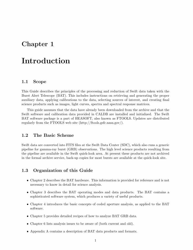
Figure 2.1: Idealized view of the Swift optical bench, including a cut-away view of the Burst AlertTelescope (BAT). The main BAT structures are the coded aperture mask (top, shown as a randomlyfilled grid, and the detector array (bottom). The narrow field instruments are mounted to the sideof the BAT.
2.4 The BAT Instrument
The BAT instrument is shown in Figure 2.1. The Burst Alert Telescope (BAT) makes the initialdetection of the gamma-ray burst (GRB), calculates a position for that burst, makes an on-boarddecision if the burst is worth an NFI follow-up observation, and sends that position to the spacecraftattitude control system, if it is worthy. It does all this within 10-30 sec of the initial trigger ofthe burst. To do this for a large number of bursts (∼100 yr-1), BAT has a large FOV (1.4 srhalf-coded & 2.2 sr partially-coded). The only way to image such a large FOV is to use the coded-aperture technique. The following sections describe the details of the design, the function of theBAT instrument, and the data products that will be available to the world community.
2.4.1 Technical Description
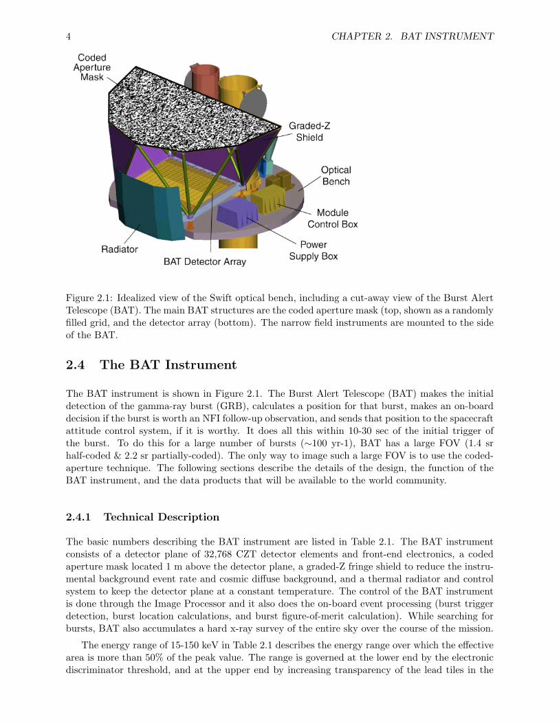
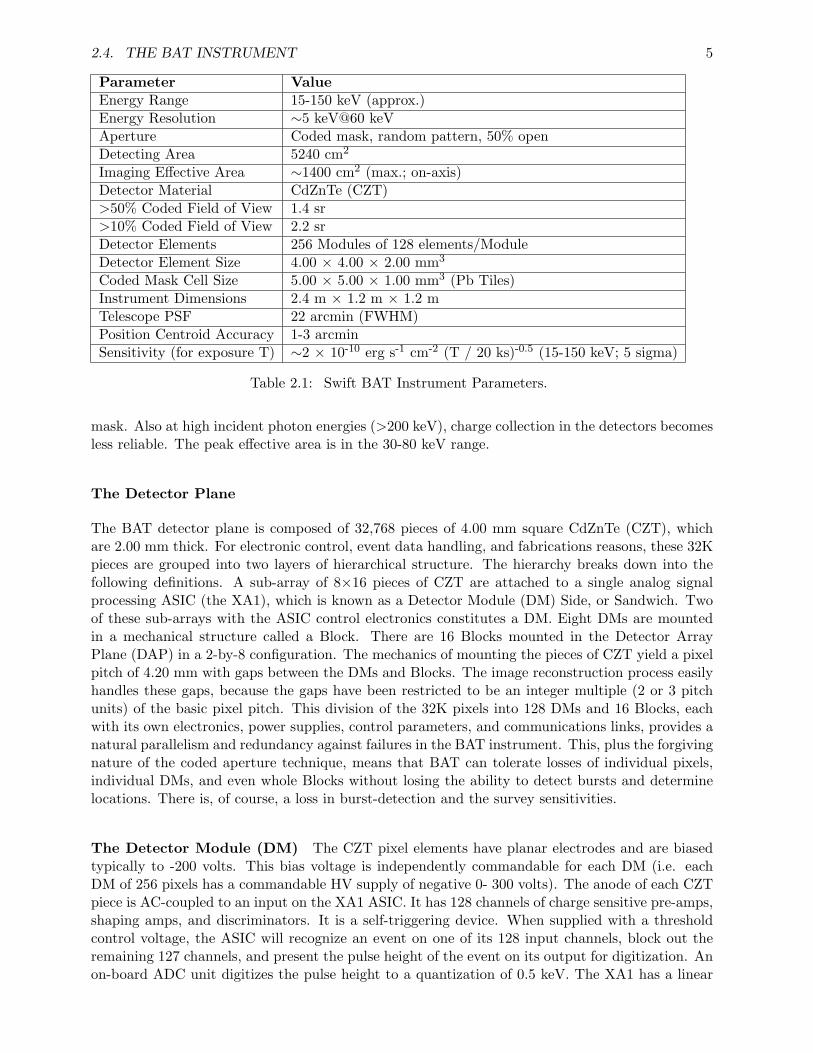
The basic numbers describing the BAT instrument are listed in Table 2.1. The BAT instrumentconsists of a detector plane of 32,768 CZT detector elements and front-end electronics, a codedaperture mask located 1 m above the detector plane, a graded-Z fringe shield to reduce the instru-mental background event rate and cosmic diffuse background, and a thermal radiator and controlsystem to keep the detector plane at a constant temperature. The control of the BAT instrumentis done through the Image Processor and it also does the on-board event processing (burst triggerdetection, burst location calculations, and burst figure-of-merit calculation). While searching forbursts, BAT also accumulates a hard x-ray survey of the entire sky over the course of the mission.
The energy range of 15-150 keV in Table 2.1 describes the energy range over which the effectivearea is more than 50% of the peak value. The range is governed at the lower end by the electronicdiscriminator threshold, and at the upper end by increasing transparency of the lead tiles in the
2.4. THE BAT INSTRUMENT 5
Parameter ValueEnergy Range 15-150 keV (approx.)Energy Resolution ∼5 keV@60 keVAperture Coded mask, random pattern, 50% openDetecting Area 5240 cm2
Imaging Effective Area ∼1400 cm2 (max.; on-axis)Detector Material CdZnTe (CZT)>50% Coded Field of View 1.4 sr>10% Coded Field of View 2.2 srDetector Elements 256 Modules of 128 elements/ModuleDetector Element Size 4.00 × 4.00 × 2.00 mm3
Coded Mask Cell Size 5.00 × 5.00 × 1.00 mm3 (Pb Tiles)Instrument Dimensions 2.4 m × 1.2 m × 1.2 mTelescope PSF 22 arcmin (FWHM)Position Centroid Accuracy 1-3 arcminSensitivity (for exposure T) ∼2 × 10⁻¹⁰ erg s-1 cm-2 (T / 20 ks)-0.5 (15-150 keV; 5 sigma)
Table 2.1: Swift BAT Instrument Parameters.
mask. Also at high incident photon energies (>200 keV), charge collection in the detectors becomesless reliable. The peak effective area is in the 30-80 keV range.
The Detector Plane
The BAT detector plane is composed of 32,768 pieces of 4.00 mm square CdZnTe (CZT), whichare 2.00 mm thick. For electronic control, event data handling, and fabrications reasons, these 32Kpieces are grouped into two layers of hierarchical structure. The hierarchy breaks down into thefollowing definitions. A sub-array of 8×16 pieces of CZT are attached to a single analog signalprocessing ASIC (the XA1), which is known as a Detector Module (DM) Side, or Sandwich. Twoof these sub-arrays with the ASIC control electronics constitutes a DM. Eight DMs are mountedin a mechanical structure called a Block. There are 16 Blocks mounted in the Detector ArrayPlane (DAP) in a 2-by-8 configuration. The mechanics of mounting the pieces of CZT yield a pixelpitch of 4.20 mm with gaps between the DMs and Blocks. The image reconstruction process easilyhandles these gaps, because the gaps have been restricted to be an integer multiple (2 or 3 pitchunits) of the basic pixel pitch. This division of the 32K pixels into 128 DMs and 16 Blocks, eachwith its own electronics, power supplies, control parameters, and communications links, provides anatural parallelism and redundancy against failures in the BAT instrument. This, plus the forgivingnature of the coded aperture technique, means that BAT can tolerate losses of individual pixels,individual DMs, and even whole Blocks without losing the ability to detect bursts and determinelocations. There is, of course, a loss in burst-detection and the survey sensitivities.
The Detector Module (DM) The CZT pixel elements have planar electrodes and are biasedtypically to -200 volts. This bias voltage is independently commandable for each DM (i.e. eachDM of 256 pixels has a commandable HV supply of negative 0- 300 volts). The anode of each CZTpiece is AC-coupled to an input on the XA1 ASIC. It has 128 channels of charge sensitive pre-amps,shaping amps, and discriminators. It is a self-triggering device. When supplied with a thresholdcontrol voltage, the ASIC will recognize an event on one of its 128 input channels, block out theremaining 127 channels, and present the pulse height of the event on its output for digitization. Anon-board ADC unit digitizes the pulse height to a quantization of 0.5 keV. The XA1 has a linear
6 CHAPTER 2. BAT INSTRUMENT
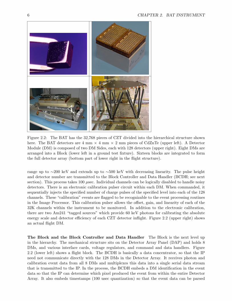
Figure 2.2: The BAT has the 32,768 pieces of CZT divided into the hierarchical structure shownhere. The BAT detectors are 4 mm × 4 mm × 2 mm pieces of CdZnTe (upper left). A DetectorModule (DM) is composed of two DM Sides, each with 128 detectors (upper right). Eight DMs arearranged into a Block (lower left in a ground test fixture). Sixteen blocks are integrated to formthe full detector array (bottom part of lower right in the flight structure).
range up to ∼200 keV and extends up to ∼500 keV with decreasing linearity. The pulse heightand detector number are transmitted to the Block Controller and Data Handler (BCDH; see nextsection). This process takes 100 µsec. Individual channels can be logically disabled to handle noisydetectors. There is an electronic calibration pulser circuit within each DM. When commanded, itsequentially injects the specified number of charge pulses of the specified level into each of the 128channels. These “calibration” events are flagged to be recognizable to the event processing routinesin the Image Processor. This calibration pulser allows the offset, gain, and linearity of each of the32K channels within the instrument to be monitored. In addition to the electronic calibration,there are two Am241 “tagged sources” which provide 60 keV photons for calibrating the absoluteenergy scale and detector efficiency of each CZT detector inflight. Figure 2.2 (upper right) showsan actual flight DM.
The Block and the Block Controller and Data Handler The Block is the next level upin the hierarchy. The mechanical structure sits on the Detector Array Panel (DAP) and holds 8DMs, and various interface cards, voltage regulators, and command and data handlers. Figure2.2 (lower left) shows a flight block. The BCDH is basically a data concentrator, so that the IPneed not communicate directly with the 128 DMs in the Detector Array. It receives photon andcalibration event data from all 8 DMs and multiplexes this data into a single serial data streamthat is transmitted to the IP. In the process, the BCDH embeds a DM identification in the eventdata so that the IP can determine which pixel produced the event from within the entire DetectorArray. It also embeds timestamps (100 usec quantization) so that the event data can be parsed
2.4. THE BAT INSTRUMENT 7
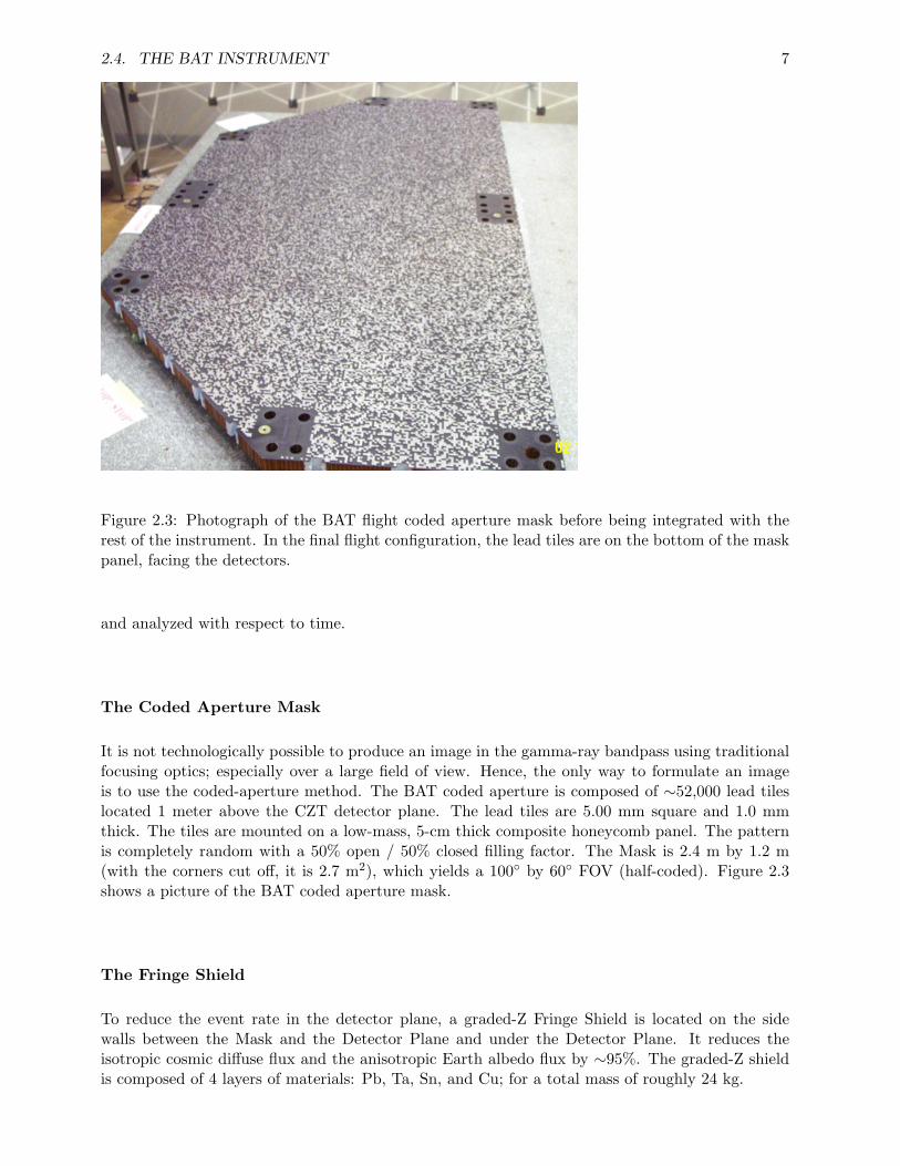
Figure 2.3: Photograph of the BAT flight coded aperture mask before being integrated with therest of the instrument. In the final flight configuration, the lead tiles are on the bottom of the maskpanel, facing the detectors.
and analyzed with respect to time.
The Coded Aperture Mask
It is not technologically possible to produce an image in the gamma-ray bandpass using traditionalfocusing optics; especially over a large field of view. Hence, the only way to formulate an imageis to use the coded-aperture method. The BAT coded aperture is composed of ∼52,000 lead tileslocated 1 meter above the CZT detector plane. The lead tiles are 5.00 mm square and 1.0 mmthick. The tiles are mounted on a low-mass, 5-cm thick composite honeycomb panel. The patternis completely random with a 50% open / 50% closed filling factor. The Mask is 2.4 m by 1.2 m(with the corners cut off, it is 2.7 m2), which yields a 100◦ by 60◦ FOV (half-coded). Figure 2.3shows a picture of the BAT coded aperture mask.
The Fringe Shield
To reduce the event rate in the detector plane, a graded-Z Fringe Shield is located on the sidewalls between the Mask and the Detector Plane and under the Detector Plane. It reduces theisotropic cosmic diffuse flux and the anisotropic Earth albedo flux by ∼95%. The graded-Z shieldis composed of 4 layers of materials: Pb, Ta, Sn, and Cu; for a total mass of roughly 24 kg.
8 CHAPTER 2. BAT INSTRUMENT
The Thermal Control System
The CZT and XA1 front-end ASIC require the operating temperature to be controlled. The nominaloperating temperature for the CZT is 20◦C with a commandable range of 0-25◦ C. The temporaland spatial thermal gradients are held to ±0.5◦C during normal operations. There are four partsto the DAP thermal control system: 1) the heaters with adjustable set points on each DM, 2) heatpipes embedded in the honeycomb plate under the Blocks to pull the heat to the sides, 3) loopheat pipes from the two side edges of the plate to pull the heat to the radiator, and 4) the thermalradiator mounted on the front side of the instrument. The radiator is 1.4 m2 and dissipates ∼200 Wof thermal power to space. Even with the radiator mounted in the anti-sun side of the spacecraft,the thermal environment the radiator sees varies over an orbit due to different Earth viewings. Toaccomodate this, the loop heat pipes are variable conductance and there are heaters attached toeach DM to actively control the temperature.
The Image Processor (IP)
The Image Processor (IP) is the BAT instrument control processor. It does seven major functions:1) collects and scans the event stream looking for rate increases (i.e. bursts), 2) calculates thesky images when there is a rate increase and scans for new point sources, 3) determines if thenewly detected burst is merits a slew request, 4) accumulates the hard x-ray survey detectorplane histograms, 5) controls the instrument and gathers housekeeping information, 6) formulatesthe BAT-portion of the telemetry stream sent to the spacecraft control computer, and 7) receivecommands from the spacecraft and processes them. These seven functions are implemented inan architecture shown in Figure 5. There are two processors within the IP. The RAD6000 isthe main instrument processor. It handles the event processing, trigger searching, housekeeping,and command, control, and telemetry functions. The 21020 DSP does image processing. A 256MB DRAM board provides all the memory for a 10-minute event-by-event ringbuffer, survey modehistograms, plus other science and engineering data products. The 1553 board provides the interfacebetween the BAT IP and the Swift spacecraft control computer.
2.4.2 Instrument Operations
The BAT instrument has two basic modes of operation: 1) scan-survey mode, and 2) burst mode.These two modes reflect the two major types of data that BAT produces: hard x-ray survey dataand burst positions. Most of BAT’s time is spent waiting for a burst to occur in its FOV. Itaccumulates events in the detector plane looking for increases in the count rate over a range oftime scales. This scanning for rate increases is the trigger algorithm. When the trigger algorithmis satisfied, it goes into burst mode. When not in burst mode and while scanning for a trigger,the instrument is accumulating spectra in each of its 32,786 detector elements every ∼5 minutes.These 32K spectra are recorded and become part of the survey data. During the scan-survey modeeach block periodically goes into calibration mode. Within the BAT flight software is the FigureOf Merit calculation that decides if the current burst trigger is worth performing a spacecraft slewmaneuver.
Burst Detection
Finding GRBs within BAT is composed of two processes: 1) the detection of the onset of a burstby looking for increases in the event rate across the detector plan, and 2) the formation of an imageof the sky using the events detected during the time interval at the beginning of the burst.
2.4. THE BAT INSTRUMENT 9
Burst Trigger Algorithm The burst trigger algorithm looks for excesses in the detector countrate above those expected from background and constant sources. The two main obstacles to GRBdetection are the variation in background and the heterogeneity of GRB time profiles. In LowEarth Orbit, detector background rates can vary by more than a factor of two during a 90-minuteorbit. The durations of GRBs range from milliseconds to minutes, during which they may haveanywhere from one to several dozen peaks in the emission. Therefore, the triggering system mustbe able to extrapolate the background and compare it to the measured detector count rate over avariety of timescales and in several energy bands.
The trigger algorithms used in BAT are based on those developed for the HETE-2 GRB Ex-plorer. The algorithm continuously applies a large number of criteria which specify the pre-burstbackground intervals (typically 0-100 sec), the order of the extrapolation of the background rate(constant, linear, and parabolic with time), the duration of the burst emission test interval (4 msecto 32 sec, these are the so called Rate Triggers), the region of the detector plane illuminated, andthe energy range (typically 4 different bandpasses). A second burst detection method is also im-plemented. Every 64 sec the detector array count rate map is processed through the FFT imagingalgorithm (on the DSP) and scanned for point sources (the so called Image Triggers). All sourcesfound are compared against an on-board catalog. Any new sources will constitute a new source andinitiates the burst response procedure. Any known source with an intensity above a commandablelevel will constitute a interesting source and initiates the interesting-source response procedure.The table of threshold levels can be adjusted after launch to balance sensitivity against the numberof false triggers, and to concentrate on specific subclasses of GRBs as they are discovered.
Burst Imaging and Location Process Once the trigger algorithm detects a count-rate excessin the detector, the data are analyzed to discover if this is due to a GRB. The IP extracts sourceand background data based on the energy range and time intervals flagged by the trigger, and thenis converted to a sky map using an FFT-based cross correlation algorithm. The algorithm requiresabout 7 seconds for the DSP to generate a 1024×512 pixel image showing the locations of transientsources. If an excess in this sky map is found, its position can be determined to within a single17-arcmin sky pixel. If a single rate trigger fails to produce a significant image excess, the BATwill check for subsequent rate increases that produce a stronger image. The ability to use imagingto eliminate false triggers is a primary advantage of the BAT, and allows us to set the triggerthresholds to a sensitivity that would be intolerable if there were no other method of confirmation.
Once the approximate source location is known, the DSP executes a back-projection algorithmwhich produces an image of that region with arbitrarily small pixel size (typically 1 arcmin), givinga peak with the intrinsic 22 arcmin FWHM PSF of the instrument. Centroiding this peak gives thesource location at the statistical and systematic limits of the instrumental accuracy (1-3 arcmindepending on the intensity of the burst).
Figure of Merit Algorithm
The Figure of Merit (FOM) algorithm is part of the spacecraft’s autonomy that decides if the burstjust detected by BAT is worth requesting a slew maneuver by the spacecraft. While the FROMdoes reside within the BAT flight software on the BAT Image Processor, the FOM provides amission-wide function which will not be described further here.

10 CHAPTER 2. BAT INSTRUMENT
Chapter 3
BAT Operating Modes and DataTypes
3.1 Introduction
The BAT flight software produces several data products. As mentioned in the previous chapter,the BAT is a photon counting instrument. That is, each photon interaction is recorded separatelyby the flight electronics and flight computer. However, like other missions there is not enoughon-board storage or downlink capacity to send all of these events to the ground. Instead, the BATsends full event data for special triggers (i.e. for gamma-ray bursts), and otherwise makes binnedproducts.
Normally, the BAT is searching for a new GRB trigger while in survey mode. In this mode,an energy spectrum is accumulated for each detector in the array on a time scale of approximatelyevery 5 minutes. While this data allows an observer to recover the fluxes of sources over longtime scales there are significant systematic errors that must be addressed, and have not yet beenaccounted for in the BAT software.
After a successful trigger, several products are produced in response to a gamma-ray burst.The most significant of these is a dump of event data which brackets the trigger time, with a totalduration of about 10-15 minutes.
The BAT also produces several products all the time, regardless of whether there is a GRBor not. These are typically various array rates, housekeeping values, and trigger diagnostics.
A more complete description of these products is presented in the rest of this chapter.
3.2 GRB Products and Response
Most of the time the BAT is in survey mode. Trigger criteria are evaluated on a continuous basis.When the BAT detects a rate increase (in one of several energy bands or spatial regions), then itindicates a “rate trigger,” which in turn initiates on-board image processing to confirm a new pointsource. Typically, there are many rate triggers per hour, each given its own trigger number, butfew are confirmed by imaging. On a periodic basis, the BAT flight software also performs imageanalysis independent of the rate triggering system, to search for slow rising GRBs and transients.
When the BAT receives a GRB trigger the BAT and the spacecraft have a preset set of responses.The typical response process is as follows, roughly in order of the time of production:
11
12 CHAPTER 3. BAT OPERATING MODES AND DATA TYPES
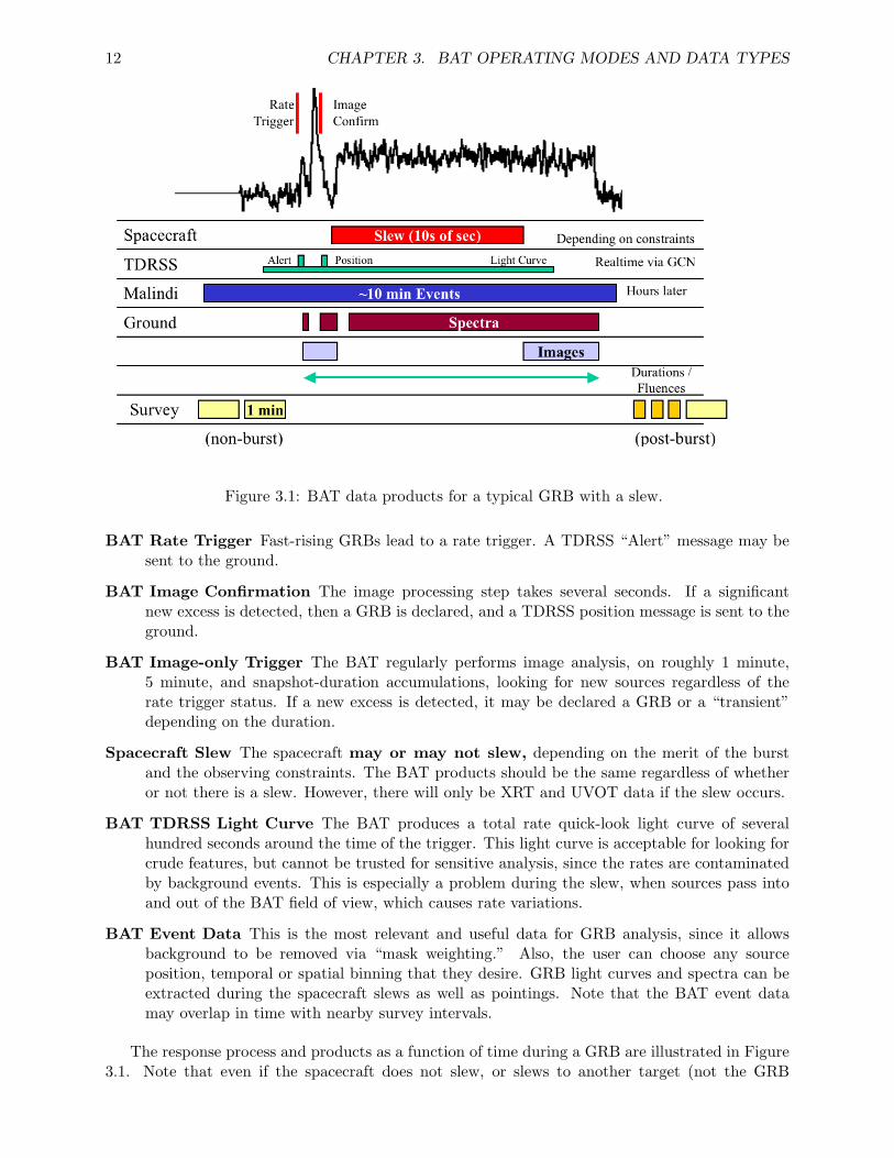
Figure 3.1: BAT data products for a typical GRB with a slew.
BAT Rate Trigger Fast-rising GRBs lead to a rate trigger. A TDRSS “Alert” message may besent to the ground.
BAT Image Confirmation The image processing step takes several seconds. If a significantnew excess is detected, then a GRB is declared, and a TDRSS position message is sent to theground.
BAT Image-only Trigger The BAT regularly performs image analysis, on roughly 1 minute,5 minute, and snapshot-duration accumulations, looking for new sources regardless of therate trigger status. If a new excess is detected, it may be declared a GRB or a “transient”depending on the duration.
Spacecraft Slew The spacecraft may or may not slew, depending on the merit of the burstand the observing constraints. The BAT products should be the same regardless of whetheror not there is a slew. However, there will only be XRT and UVOT data if the slew occurs.
BAT TDRSS Light Curve The BAT produces a total rate quick-look light curve of severalhundred seconds around the time of the trigger. This light curve is acceptable for looking forcrude features, but cannot be trusted for sensitive analysis, since the rates are contaminatedby background events. This is especially a problem during the slew, when sources pass intoand out of the BAT field of view, which causes rate variations.
BAT Event Data This is the most relevant and useful data for GRB analysis, since it allowsbackground to be removed via “mask weighting.” Also, the user can choose any sourceposition, temporal or spatial binning that they desire. GRB light curves and spectra can beextracted during the spacecraft slews as well as pointings. Note that the BAT event datamay overlap in time with nearby survey intervals.
The response process and products as a function of time during a GRB are illustrated in Figure3.1. Note that even if the spacecraft does not slew, or slews to another target (not the GRB
3.2. GRB PRODUCTS AND RESPONSE 13
position), event data should still be produced. As long as the source is in the BAT field of view, itshould be possible to reconstruct the GRB light curve and spectrum.
3.2.1 Important Notes About Trigger Times
There are several important things to realize about trigger times. The BAT trigger time associatedwith each GRB is almost arbitrary. The trigger time does not necessarily correspond to the peakflux or the start of the burst. For example, the BAT may trigger on the first peak of a multi-peakburst; or, it may trigger on the second peak after a slew. The trigger time simply corresponds tothe start of the time interval which the BAT flight software used to find a significant image excess.Therefore, when a precise definition of time is needed for scientific analysis, users should exercisetheir scientific judgement to assign the zero point of the time scale.
Also, it is important to know that for short bursts the trigger time may be incorrect byup to 320 milliseconds. For short triggers (trigger durations < 64 milliseconds) the BAT flightsoftware reports a trigger time which has been rounded down (earlier) to the nearest multiple of320 millisecond. Thus, it is important to examine the entire range of T+0 to T+320 millisecondsof light curves of short triggers.
3.2.2 Description of Standard Products
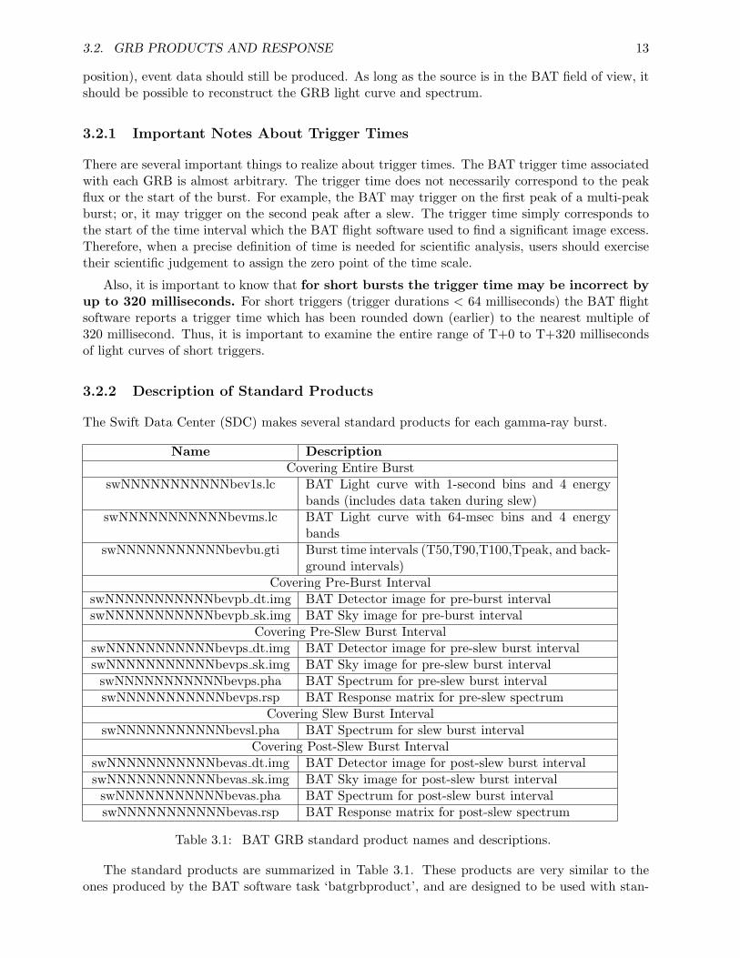
The Swift Data Center (SDC) makes several standard products for each gamma-ray burst.
Name DescriptionCovering Entire Burst
swNNNNNNNNNNNbev1s.lc BAT Light curve with 1-second bins and 4 energybands (includes data taken during slew)
swNNNNNNNNNNNbevms.lc BAT Light curve with 64-msec bins and 4 energybands
swNNNNNNNNNNNbevbu.gti Burst time intervals (T50,T90,T100,Tpeak, and back-ground intervals)
Covering Pre-Burst IntervalswNNNNNNNNNNNbevpb dt.img BAT Detector image for pre-burst intervalswNNNNNNNNNNNbevpb sk.img BAT Sky image for pre-burst interval
Covering Pre-Slew Burst IntervalswNNNNNNNNNNNbevps dt.img BAT Detector image for pre-slew burst intervalswNNNNNNNNNNNbevps sk.img BAT Sky image for pre-slew burst intervalswNNNNNNNNNNNbevps.pha BAT Spectrum for pre-slew burst intervalswNNNNNNNNNNNbevps.rsp BAT Response matrix for pre-slew spectrum
Covering Slew Burst IntervalswNNNNNNNNNNNbevsl.pha BAT Spectrum for slew burst interval
Covering Post-Slew Burst IntervalswNNNNNNNNNNNbevas dt.img BAT Detector image for post-slew burst intervalswNNNNNNNNNNNbevas sk.img BAT Sky image for post-slew burst intervalswNNNNNNNNNNNbevas.pha BAT Spectrum for post-slew burst intervalswNNNNNNNNNNNbevas.rsp BAT Response matrix for post-slew spectrum
Table 3.1: BAT GRB standard product names and descriptions.
The standard products are summarized in Table 3.1. These products are very similar to theones produced by the BAT software task ‘batgrbproduct’, and are designed to be used with stan-
14 CHAPTER 3. BAT OPERATING MODES AND DATA TYPES
dard FTOOLS software for imaging, timing, and spectral analysis in X-ray astronomy. While thestandard pipleline products are ready-made for rapid analysis, the SDC pipeline may not alwaysbe able to use the newest software, and is constrained to produce only a small number of datafiles. The BAT team recommends that for serious scientific analysis, users should make their owncustom science products using ‘batgrbproduct’.
Spectra and response matrices have standard extensions, and are suitable for analysis withXSPEC.
Light curves are uniformly sampled and have multiple energy channels. They can be viewedeasily with the general FITS viewer ‘fv’, but also with other timing analysis software such asXRONOS (lcurve, powspec, etc.). Multiple channel light curves can be handled in XRONOS usingthe “feN” and “leN” energy band options.
Both detector and sky image files are produced. Detector images are processed with BATdeconvolution software (batfftimage) to produce sky flux images. The first four extensions of eachfile are the detector/sky images in each of four standard energy bands. There are also GTI andEBOUNDS extensions. Following that, there is a BAT DPI TOT/BAT IMAGE TOT extensionwhich contains the full energy band. All of these images are standard FITS image extensions whichcan be viewed with DS9, fv, or your image viewer of choice.
The “pre-slew” sky image (swNNNNNNNNNNNbevps sk.img) has a special BAT CATALOGas its last extension, which was produced by batcelldetect. The columns RA OBJ,DEC OBJof this file represent a fit to the position of the source using all pre-slew data. Because the fullpre-slew burst interval usually contains more data than the BAT on-board trigger interval, thisposition will usually be a more precise measure of the source position.
The “GTI” file contains multiple time intervals of interest for a gamma-ray burst, includingT50, T90, T100 (estimated total burst interval), and various background intervals. These intervalsare computed by the battblocks task. They are standard GTIs which can be use for time filteringof Swift data.
The time intervals identified in the table are defined in the following way:
• pre-burst means before any significant burst emission;
• pre-slew means burst emission before the spacecraft slews to the burst location;
• slew means burst emission during the slew to the burst location;
• post-slew means burst emission after the slew to the burst location;
These intervals are entirely separate from the trigger time calculated by BAT on-board thespacecraft.
Not all of the data files will be present for every burst. In some cases, the spacecraft doesnot slew to the burst, so there may not be slew or post-slew products. Also, occasionally thebattblocks task fails to find sensible time intervals, in which case no standard products will bepresent (this most often occurs for faint, short bursts).
3.3 Non-GRB Products
The BAT also generates products that are not associated with a particular gamma-ray burst. Theseare typically produced continuously, or at regular intervals in the course of normal operations.
3.3. NON-GRB PRODUCTS 15
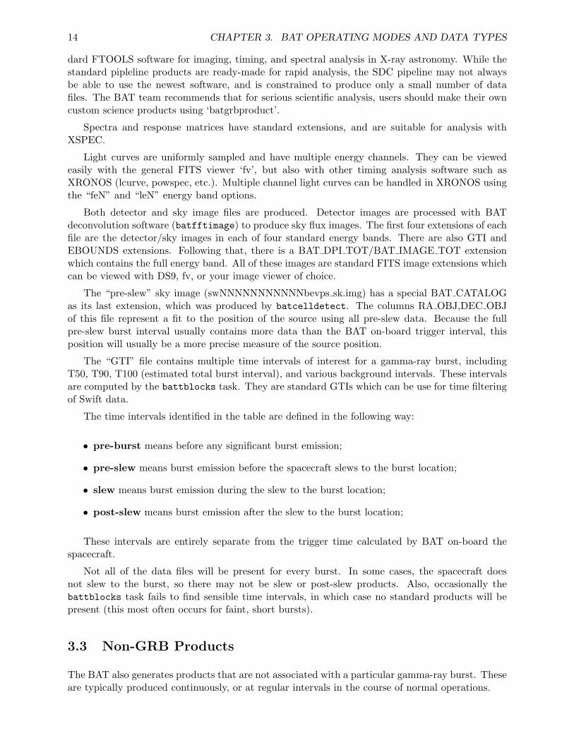
Figure 3.2: Representation of a detector plane histogram (DPH).
Descriptions of the formats of these products can be found in Appendix A (“BAT Data For-mats”).
3.3.1 Survey Data
When not responding to a GRB trigger, the BAT is typically in survey mode. In this mode, theevent data from the array is collected into detector plane histograms (DPHs) by the flight software.
These histograms have an 80-bin spectrum for each detector in the array (i.e. 32k detectors ×80 bins) during the integration period. The energy bin widths are variable from one energy bin tothe next, but have remained constant in time throughout the mission to date. Each survey DPH filerecords the energy binning used (in the FITS file, there is an EBOUNDS extension which containsthis information). Figure 3.2 shows a representation of a survey DPH. It is three dimensional inthe sense that there are two spatial dimension and one spectral dimension.
Survey data have a crude energy correction applied on-board, but should usually be furthercorrected using the task baterebin.
Typically, DPHs are integrated for five minutes, but this duration is not always the same.In some cases longer or shorter durations have been used for operational reasons (e.g., telemetryreduction or to get diagnostic information about the instrument). Also, survey intervals are alwaysterminated when the spacecraft begins a slew to a new target or when entering the SAA. Generallyspeaking, the survey data cannot be used to search for time variations on time-scales shorter than5 minutes.
Survey data is particularly difficult to analyze. It contains the longest sky integrations, andthus is potentially the most sensitive to hard X-ray sources, but also contains the greatest numberof systematic error contributions. Currently the BAT team does not support general survey dataanalysis.
3.3.2 Rate Data
The BAT produces continuous streams of rate data. While these may be used for scientific analysis,they are also used by the on-board flight software for trigger searching and reporting the instrumentstate of health.
16 CHAPTER 3. BAT OPERATING MODES AND DATA TYPES
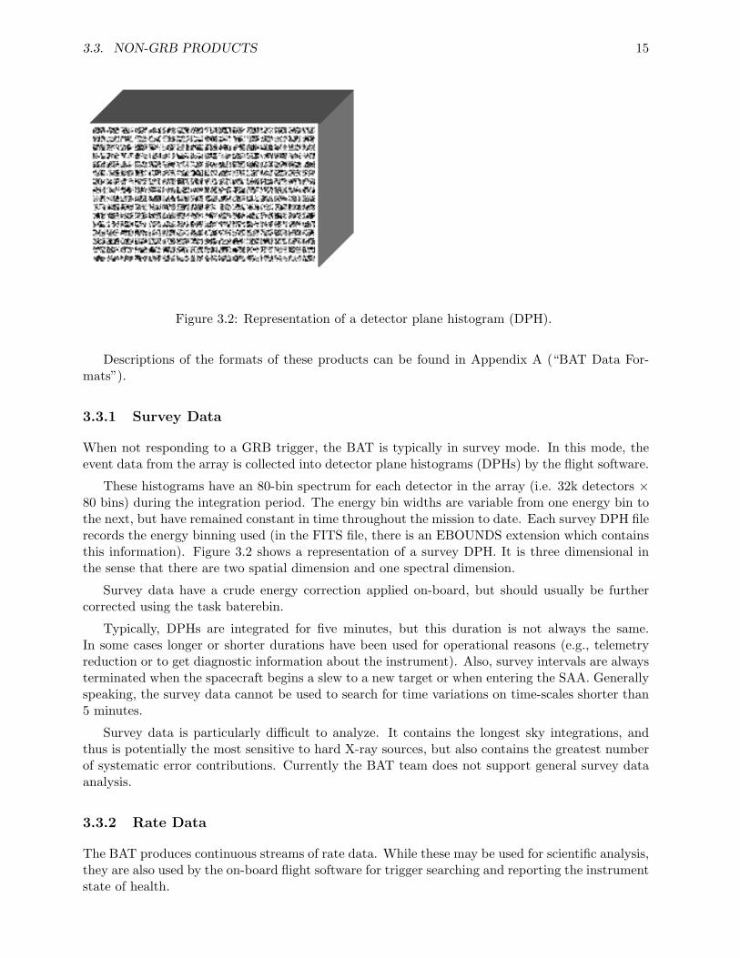
Figure 3.3: Example of BAT 1 second rates. All variations shown are due to the space environmentand not an astrophysical source.
The rate data include:
• one-second rates (1 sec sampling; full energy band; full array);
• 64 msec rates (64 msec sampling; four energy bands; full array);
• quadrant rates (1.6 sec sampling; four energy bands; four separate spatial quadrants);
• mask-tagged rates (1.6 sec sampling; four energy bands; three distinct sources);
• maximum rates (maximum counts recorded for multiple time scales, energy bands andspatial regions).
All rate data except for mask-tagged rate data are not background subtracted. This meansthat the hard X-ray background and particle backgrounds are included in the rates. Also, sincethere is no per-detector information recorded in the rate data, it is possible for noisy detectors togenerate rapid spikes which may emulate a gamma-ray burst or other rapidly varying phenomenon.Thus, while rate variations may be suggestive of an astrophysical event, conclusive proof must beobtained from image analysis.
3.3. NON-GRB PRODUCTS 17
Figure 3.3 shows an example 1 second BAT rate light curve, with a typical background level andvariation for a portion of the orbit. Swift spacecraft orbits which pass near the SAA can produceBAT rates as high as 105 counts per second.
Mask tagged data are generated on-board by the BAT flight software, and contain a crude lightcurve of up to three astrophysical sources. These sources are chosen automatically by the flightsoftware at the time of data collection. The raw mask tagged data may be converted to backgroundsubtracted light curves using the batmasktaglc software task.
3.3.3 Maps
The BAT flight software periodically produces housekeeping maps which are useful for BAT analy-sis. The most important of these are detector enable/disable maps and gain/offset maps. Detectorenable/disable maps represent which detectors have been automatically disabled. Usually detec-tors are disabled because they are noisy. The number of enabled detectors must be taken intoaccount when performing mask weighting and image analysis.
Gain/offset maps are produced by the automatic calibration system. They record the approx-imate pulse-height-to-energy calibration for each detector. This map, in combination with groundcalibration files, is used to produce calibrated event lists (using bateconvert) and survey files (usingbaterebin).
Mask weight maps are associated with mask tagged rates, and are needed to produce back-ground subtracted light curves. In the standard FITS products, mask weight maps should beattached to the mask tagged light curve files.
3.3.4 Trend Products
Various other tables and maps are generated as well. These can be broken down into several broadcategories:
• detector maps used in on-board imaging (“scaled” maps);
• calibration pulser maps used to produce gain/offset maps on-board;
• trigger diagnostic tables for rate (long and short) and image trigger systems;
• the on-board source catalog;
• americium tagged-source spectra (“block spectra”) and survey-type data (“Americium DPHs”),which are used to calibrate the absolute energy scale;
• science housekeeping (“DAP HK”), plus various diagnostics;
• engineering housekeeping;
• debug stream (an ASCII log of the flight software activities);
As noted above, a more detailed description of the format and content of all the products canbe found in Appendix A.

18 CHAPTER 3. BAT OPERATING MODES AND DATA TYPES
Chapter 4
Introduction to BAT Analysis
4.1 Introduction
This chapter contains a discussion of the basics of coded mask analysis, differences from directimaging systems, and useful science information about the BAT, like the coordinate system andunits.
4.2 Coded Apertures: Basic Concepts
The BAT instrument has a coded aperture. The basic premise of a coded aperture is quite differentfrom normal imaging optics, primarily because there are no focussing optics. All of the “optical”elements of a coded aperture are passive, involving the casting shadows from the aperture (mask)onto an imaging sensor.
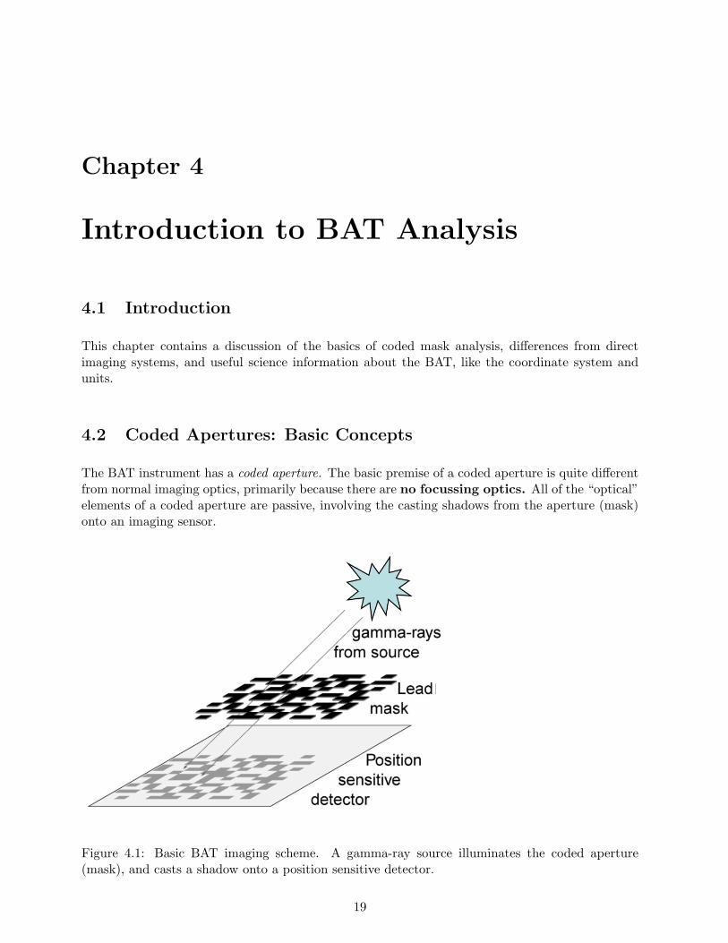
Figure 4.1: Basic BAT imaging scheme. A gamma-ray source illuminates the coded aperture(mask), and casts a shadow onto a position sensitive detector.
19
20 CHAPTER 4. INTRODUCTION TO BAT ANALYSIS
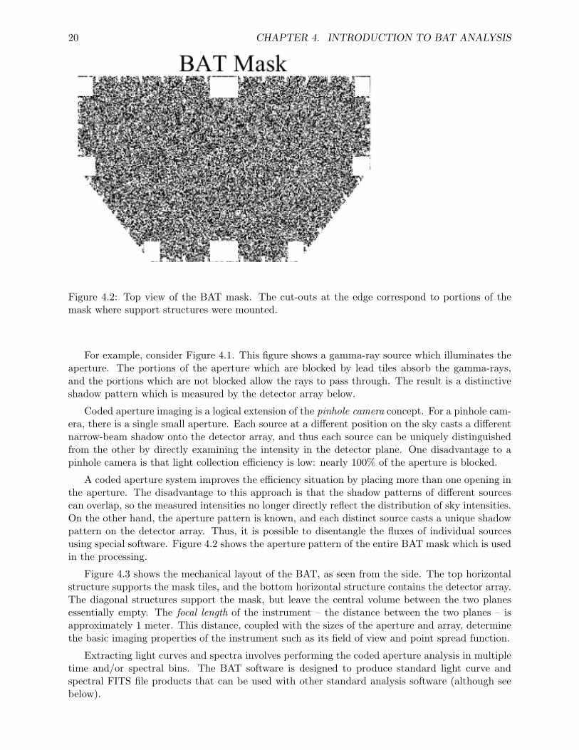
Figure 4.2: Top view of the BAT mask. The cut-outs at the edge correspond to portions of themask where support structures were mounted.
For example, consider Figure 4.1. This figure shows a gamma-ray source which illuminates theaperture. The portions of the aperture which are blocked by lead tiles absorb the gamma-rays,and the portions which are not blocked allow the rays to pass through. The result is a distinctiveshadow pattern which is measured by the detector array below.
Coded aperture imaging is a logical extension of the pinhole camera concept. For a pinhole cam-era, there is a single small aperture. Each source at a different position on the sky casts a differentnarrow-beam shadow onto the detector array, and thus each source can be uniquely distinguishedfrom the other by directly examining the intensity in the detector plane. One disadvantage to apinhole camera is that light collection efficiency is low: nearly 100% of the aperture is blocked.
A coded aperture system improves the efficiency situation by placing more than one opening inthe aperture. The disadvantage to this approach is that the shadow patterns of different sourcescan overlap, so the measured intensities no longer directly reflect the distribution of sky intensities.On the other hand, the aperture pattern is known, and each distinct source casts a unique shadowpattern on the detector array. Thus, it is possible to disentangle the fluxes of individual sourcesusing special software. Figure 4.2 shows the aperture pattern of the entire BAT mask which is usedin the processing.
Figure 4.3 shows the mechanical layout of the BAT, as seen from the side. The top horizontalstructure supports the mask tiles, and the bottom horizontal structure contains the detector array.The diagonal structures support the mask, but leave the central volume between the two planesessentially empty. The focal length of the instrument – the distance between the two planes – isapproximately 1 meter. This distance, coupled with the sizes of the aperture and array, determinethe basic imaging properties of the instrument such as its field of view and point spread function.
Extracting light curves and spectra involves performing the coded aperture analysis in multipletime and/or spectral bins. The BAT software is designed to produce standard light curve andspectral FITS file products that can be used with other standard analysis software (although seebelow).
4.3. CODED APERTURE ANALYSIS FOR X-RAY ASTRONOMERS 21
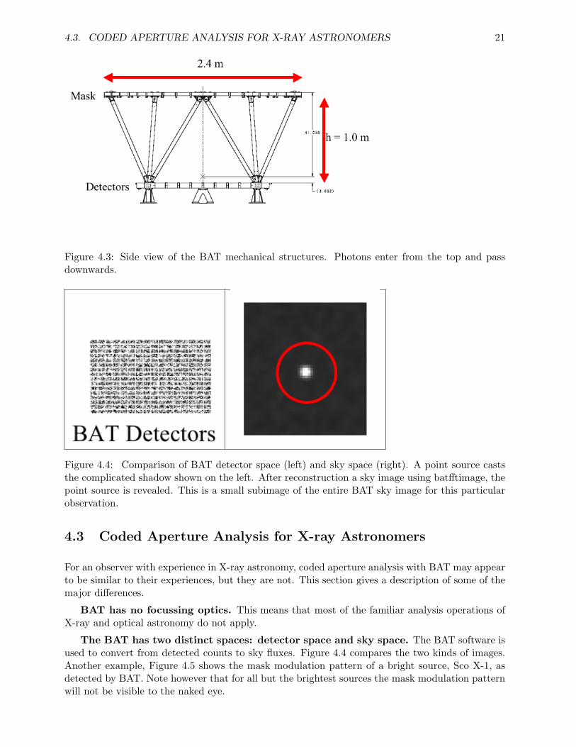
Figure 4.3: Side view of the BAT mechanical structures. Photons enter from the top and passdownwards.
Figure 4.4: Comparison of BAT detector space (left) and sky space (right). A point source caststhe complicated shadow shown on the left. After reconstruction a sky image using batfftimage, thepoint source is revealed. This is a small subimage of the entire BAT sky image for this particularobservation.
4.3 Coded Aperture Analysis for X-ray Astronomers
For an observer with experience in X-ray astronomy, coded aperture analysis with BAT may appearto be similar to their experiences, but they are not. This section gives a description of some of themajor differences.
BAT has no focussing optics. This means that most of the familiar analysis operations ofX-ray and optical astronomy do not apply.
The BAT has two distinct spaces: detector space and sky space. The BAT software isused to convert from detected counts to sky fluxes. Figure 4.4 compares the two kinds of images.Another example, Figure 4.5 shows the mask modulation pattern of a bright source, Sco X-1, asdetected by BAT. Note however that for all but the brightest sources the mask modulation patternwill not be visible to the naked eye.
22 CHAPTER 4. INTRODUCTION TO BAT ANALYSIS
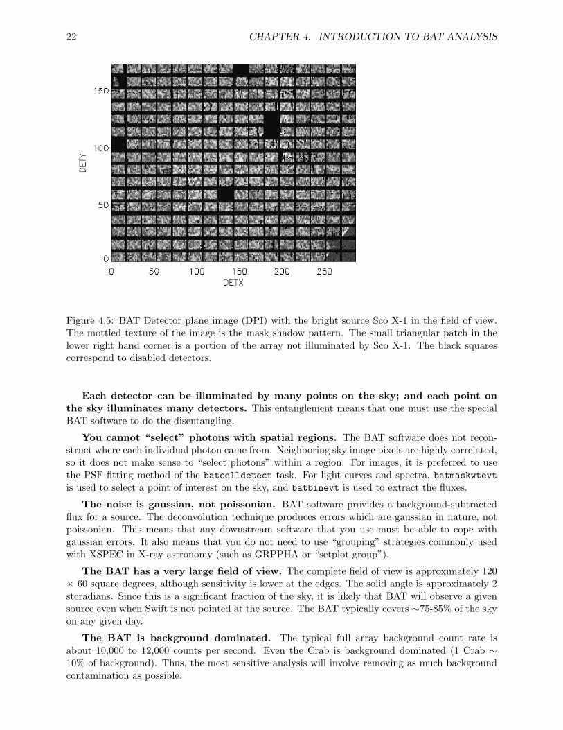
Figure 4.5: BAT Detector plane image (DPI) with the bright source Sco X-1 in the field of view.The mottled texture of the image is the mask shadow pattern. The small triangular patch in thelower right hand corner is a portion of the array not illuminated by Sco X-1. The black squarescorrespond to disabled detectors.
Each detector can be illuminated by many points on the sky; and each point onthe sky illuminates many detectors. This entanglement means that one must use the specialBAT software to do the disentangling.
You cannot “select” photons with spatial regions. The BAT software does not recon-struct where each individual photon came from. Neighboring sky image pixels are highly correlated,so it does not make sense to “select photons” within a region. For images, it is preferred to usethe PSF fitting method of the batcelldetect task. For light curves and spectra, batmaskwtevtis used to select a point of interest on the sky, and batbinevt is used to extract the fluxes.
The noise is gaussian, not poissonian. BAT software provides a background-subtractedflux for a source. The deconvolution technique produces errors which are gaussian in nature, notpoissonian. This means that any downstream software that you use must be able to cope withgaussian errors. It also means that you do not need to use “grouping” strategies commonly usedwith XSPEC in X-ray astronomy (such as GRPPHA or “setplot group”).
The BAT has a very large field of view. The complete field of view is approximately 120× 60 square degrees, although sensitivity is lower at the edges. The solid angle is approximately 2steradians. Since this is a significant fraction of the sky, it is likely that BAT will observe a givensource even when Swift is not pointed at the source. The BAT typically covers ∼75-85% of the skyon any given day.
The BAT is background dominated. The typical full array background count rate isabout 10,000 to 12,000 counts per second. Even the Crab is background dominated (1 Crab ∼10% of background). Thus, the most sensitive analysis will involve removing as much backgroundcontamination as possible.
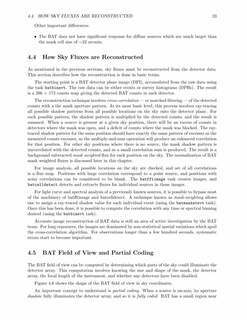
4.4. HOW SKY FLUXES ARE RECONSTRUCTED 23
Other important differences:
• The BAT does not have significant response for diffuse sources which are much larger thanthe mask cell size of ∼22 arcmin.
4.4 How Sky Fluxes are Reconstructed
As mentioned in the previous sections, sky fluxes must be reconstructed from the detector data.This section describes how the reconstruction is done in basic terms.
The starting point is a BAT detector plane image (DPI), accumulated from the raw data usingthe task batbinevt. The raw data can be either events or survey histograms (DPHs). The resultis a 286 × 173 counts map giving the detected BAT counts in each detector.
The reconstruction technique involves cross-correlation — or matched filtering — of the detectedcounts with a the mask aperture pattern. At its most basic level, this process involves ray-tracingall possible shadow patterns from all possible locations on the sky onto the detector plane. Foreach possible pattern, the shadow pattern is multiplied by the detected counts, and the result issummed. When a source is present at a given sky position, there will be an excess of counts indetectors where the mask was open, and a deficit of counts where the mask was blocked. The ray-traced shadow pattern for the same position should have exactly the same pattern of excesses as themeasured counts excesses, so the multiply-and-sum operation will produce an enhanced correlationfor that position. For other sky positions where there is no source, the mask shadow pattern isuncorrelated with the detected counts, and so a small correlation sum is produced. The result is abackground subtracted mask weighted flux for each position on the sky. The normalization of BATmask weighted fluxes is discussed later in this chapter.
For image analysis, all possible locations on the sky are checked, and set of all correlationsis a flux map. Positions with large correlation correspond to a point source, and positions withnoisy correlations can be considered to be blank. The batfftimage task creates images, andbatcelldetect detects and extracts fluxes for individual sources in those images.
For light curve and spectral analysis of a previously known sources, it is possible to bypass mostof the machinery of batfftimage and batcelldetect. A technique known as mask-weighting allowsone to assign a ray-traced shadow value for each individual event (using the batmaskwtevt task).Once this has been done, it is possible to compute the correlation with any time or spectral binningdesired (using the batbinevt task).
Accurate image reconstruction of BAT data is still an area of active investigation by the BATteam. For long exposures, the images are dominated by non-statistical spatial variations which spoilthe cross-correlation algorithm. For observations longer than a few hundred seconds, systematicerrors start to become important.
4.5 BAT Field of View and Partial Coding
The BAT field of view can be computed by determining which parts of the sky could illuminate thedetector array. This computation involves knowing the size and shape of the mask, the detectorarray, the focal length of the instrument, and whether any detectors have been disabled.
Figure 4.6 shows the shape of the BAT field of view in sky coordinates.
An important concept to understand is partial coding. When a source is on-axis, its apertureshadow fully illuminates the detector array, and so it is fully coded. BAT has a small region near
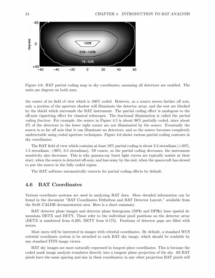
24 CHAPTER 4. INTRODUCTION TO BAT ANALYSIS
Figure 4.6: BAT partial coding map in sky coordinates, assuming all detectors are enabled. Theunits are degrees on both axes.
the center of its field of view which is 100% coded. However, as a source moves farther off axis,only a portion of the aperture shadow will illuminate the detector array, and the rest are blockedby the shield which surrounds the BAT instrument. The partial coding effect is analogous to theoff-axis vignetting effect for classical telescopes. The fractional illumination is called the partialcoding fraction. For example, the source in Figure 4.5 is about 98% partially coded, since about2% of the detectors in the lower right corner are not illuminated by the source. Eventually thesource is so far off axis that it can illuminate no detectors, and so the source becomes completelyundetectable using coded aperture techniques. Figure 4.6 shows various partial coding contours insky coordinates.
The BAT field of view which contains at least 10% partial coding is about 2.2 steradians (>50%,1.5 steradians; >90%, 0.5 steradians). Of course, as the partial coding decreases, the instrumentsensitivity also decreases. This is why gamma-ray burst light curves are typically noisier at theirstart, when the source is detected off-axis; and less noisy by the end, when the spacecraft has slewedto put the source in the fully coded region.
The BAT software automatically corrects for partial coding effects by default.
4.6 BAT Coordinates
Various coordinate systems are used in analyzing BAT data. More detailed information can befound in the document ”BAT Coordinates Definition and BAT Detector Layout,” available fromthe Swift CALDB documentation area. Here is a short summary.
BAT detector plane images and detector plane histograms (DPIs and DPHs) have spatial di-mensions DETX and DETY. These refer to the individual pixel positions on the detector array(DETX is numbered from 0-285; DETY from 0-172). Positions of detector gaps are filled withzeroes.
Most users will be interested in images with celestial coordinates. By default, a standard WCScelestial coordinate system is be attached to each BAT sky image, which should be readable byany standard FITS image viewer.
BAT sky images are most naturally expressed in tangent plane coordinates. This is because thecoded mask image analysis translates directly into a tangent plane projection of the sky. All BATpixels have the same spacing and size in these coordinates; in any other projection BAT pixels will
4.7. DEFINITION OF BAT COUNT UNITS AND CORRECTIONS 25
appear distorted. In terms of true solid angle however, BAT sky pixels far off-axis are significantlysmaller than the on-axis ones (by as much as a factor of two). While in principle this allows oneto determine source positions more accurately, the sensitivity is also much less far off-axis due topartial coding effects.
All BAT images contain a secondary tangent plane coordinate system (WCS-T), which is labeledwith the axes IMX and IMY. These coordinates are the tangent of the off-axis angle in the X andY directions (the boresight is centered at 0,0).
The BAT also has an instrumental longitude/co-latitude system. The co-latitude component,“theta,” measures the off-axis angle in degrees. The other component, “phi,” measures the longitudeof a source, starting at the instrument X axis. Both of these values are reported in BAT GRBproducts.
4.7 Definition of BAT Count Units and Corrections
This section describes the “mask weighted” counts and rates that are computed by the proceduresdescribed above. Generally speaking, if the default corrections are applied, light curves and spectrawill be adjusted to be comparable to an on-axis source, independent of the number of illuminatedor active detectors. However, if the user chooses non-default corrections, then this property mayno longer hold true. Each of the corrections is discussed below.
4.7.1 Definition of BAT Mask-Weighted Counts
BAT counts derived from mask weighting procedures or sky imaging – batmaskwtevt, batmaskw-timg or batfftimage – and using the default corrections are defined in the following way:
Background subtracted counts per fully illuminated detectorfor an equivalent on-axis source
Rate is defined similarly, per unit time.
Let us examine what each of these words means. Next to each phrase is the correspondingcorrection that can be used in the analysis tasks. These corrections apply to both the maskweighting programs and the sky imaging programs (which fundamentally apply the same technique).
Background subtracted counts...
The units are counts, not photons, which customary for X- and gamma-ray instruments. Toconvert to photon fluxes, one must generally fit the spectrum to an a priori model. However, themask weighting technique provides automatic background subtraction.
Also the ‘background’ that is subtracted includes the effects of flux that passes through thelead mask cells without scattering. Both foreground and background include counts from photonsthat scatter off the lead mask cells and other parts of the BAT and Swift structure.
... per ... detector (correction ’ndets’)
The counts are normalized to the number of enabled BAT detectors. This compensates for thepossibility that some, or many, BAT detectors are disabled for a given observation.
26 CHAPTER 4. INTRODUCTION TO BAT ANALYSIS
... per ... *illuminated* detector ... (correction ’pcode’)
The ‘pcode’ correction normalizes the counts by the number of illuminated detectors. Since theBAT is a wide-field instrument it is possible, indeed likely, that sources will be at the edge of thefield of view. This means that only a fraction of the detector array is illuminated by through mask,i.e. the source is partially coded, and thus will produce fewer counts. This correction normalizesthe partial coding fraction to unity for all sources.
... per *fully illuminated* detector ... (correction ’maskwt’)
Even when detectors are illuminated by a source, most detectors are not 100% illuminated. Ingeneral, there is a distribution of detector illumination fractions, ranging from 0% (fully shadowedby the mask) to 100% (fully illuminated by the mask). The mask weighting technique used by theBAT software combines all events to produce background-subtracted counts in a “mean” fraction-ally illuminated detector. The ‘maskwt’ correction renormalizes the counts to be those received ina fully illuminated detector. This accounts for both the open fraction of the mask (50% for theBAT), plus the per-detector partial illumination.
The ‘maskwt’ correction should be distinguished from the partial coding correction. The partialcoding correction adjusts for the fractional number of detectors that a source could illuminatethrough the mask, regardless of which mask cells are blocked or open. The ‘maskwt’ correctionadjusts for the partial illumination of each individual detector.
... for an equivalent on-axis source* (correction ’flatfield’)
Off-axis sources have a different count rate because the projected area of the BAT detectors ischanged by projection effects. Generally, the effective area is reduced off-axis because of the “cosineeffect.” However, the effective area increases slightly for mild off-axis angles because detector sidesare illuminated. The ‘flatfield’ correction adjusts for these effects, to create a count rate for aneffective on-axis source. In this manner, it will be more practical to compare detections of the samesource at different positions in the field of view.
It should be noted that this correction is primarily due to geometric effects. It is also understoodthat off-axis illumination changes the detector response in non-subtle ways, which is not correctedfor by the ‘flatfield’ correction.
4.7.2 Converting to a counts per area
The area of a single BAT detector is 0.16 cm2. Thus, the conversion between “per unit area” and”per fully illuminated detector” is:
counts_cm2 = counts_fully_illuminated_det / 0.16
Chapter 5
BAT Analysis Procedures
5.1 Introduction
This chapter provides information and recipes regarding the analysis of BAT data. The primaryfocus of the information is extracting light curves, spectra and images from the event data associatedwith gamma-ray bursts.
In response to a gamma-ray burst, the BAT instrument sends raw event data to the ground.This event data includes all events from particle background, noisy detectors, and non-imaged X-rays. The user must take advantage of the coded mask analysis in order to remove the effects ofthese nuisance components. The technique described here is known as “mask-weighting,” which isequivalent to a specialized form of ray-tracing.
It should be noted that event data allows maximum flexibility to analyze the data. For example,the user can select which time intervals they are interested in, and the desired spectral binning.(Contrast this with survey data, which has a fixed integration time and energy binning scheme.)The BAT software and hardware has also been designed to allow the user to extract light curves andspectra while the spacecraft is slewing. This is important because the Swift spacecraft automaticallyslews to most bursts, and a significant fraction of the bursts have prompt emission during the slew.
For most GRB analysis, users should begin with the ‘batgrbproduct’ script. This script, de-scribed in the following sections, performs a standard analysis and makes products that will satisfymany users.
However, this chapter also describes some of the more fundamental building-block analysisprocedures, including:
• Energy calibration of events
• Making a detector quality map
• Mask Weighting (Ray Tracing) for a known source position
• Extracting a light curve
• Extracting a spectrum
• Correcting the spectrum
• Generating a response matrix
• Making sky images
27
28 CHAPTER 5. BAT ANALYSIS PROCEDURES
5.2 Complete GRB Processing Script
This section describes how to run automatic GRB processing script, batgrbproduct. This scriptproduces light curves, spectra and summary reports that many common users would want. It alsoproduces a detailed log of commands executed, which users can cut and paste to make their ownproducts.
5.2.1 Introduction
In late 2006, a new version of the BAT software became available which includes the taskbatgrbproduct. This task generates standard products for a GRB observation, using conser-vative data filtering and sensible defaults. The BAT team recommends that most users start withthis script for their analysis of a GRB. The BAT team itself uses this script to produce the re-sults posted on GCN circulars. The batgrbproduct script performs the mask weighting operation(ray-tracing), creates a quality map, and generates light curves spectra and response matrices withvarious binnings. Sky images are produced, and if possible, a refined GRB position is derived fromthese positions.
The task also produces a detailed log file which users can consult when they want to make theirown custom light curves or spectra.
5.2.2 Prerequisites
• A complete Swift observation containing GRB event data (usually this will be in observationsegment 0, labeled NNNNNNNNN000 with three final zeroes);
• a recent version of HEASoft tools (version 6.1.2 or later);
• a recent version of CALDB.
It is assumed that the correct energy calibration has been run on the event file. Please see thesection on applying an energy calibration to BAT event data for more information.
5.2.3 Change to Data Directory
Change to the directory containing the observation, but not into the observation directory it-self. Extract the observation data if needed. For example, if the observation directory was/data/grbs/00145675000, then issue the following command,
cd /data/grbs
5.2.4 Creating GRB Products Automatically
To run the script, issue the following command,
batgrbproduct indir=./00145675000 outdir=./00145675000-results
where
5.2. COMPLETE GRB PROCESSING SCRIPT 29
• indir is the observation directory
• outdir is the output results directory
The script will print diagnostic output to the console as it runs, and may take tens of minutesto an hour to complete, depending on the speed of your computer and hard drive. When the scriptfinishes, it should print an inventory of the results.
5.2.5 Results
The results are stored in the ‘outdir’ directory you specified on the command line. A summary ofthe results of the analysis is stored in the file report.txt in that directory.
Light curves, spectra and images are stored in the lc, pha and img subdirectories, respectively.Response matrices are generated for the pre-slew and post-slew time intervals. Burst durationmeasures are reported in report.txt, and also are contained in the gti subdirectory.
More information about the results can be found in the documentation for the batgrbproduct.
5.2.6 When Things Go Wrong
There are several situations where batgrbproduct may not be able to perform a totally automaticanalysis.
If the burst is very faint, especially a short hard burst, the automatic software is not always ableto select the right time interval. If that is the case, the script defaults to the time interval reportedin the TDRSS position message, which may not always be appropriate. Users may always overridethe default time interval by hand, using the trigtime/trigstop/backstrt/backstop parameters. Theuser can also override the default position by using the ‘ra’ and ‘dec’ parameters. By default,batgrbproduct uses the reported BAT position, and not the XRT position.
The Swift spacecraft does not always respond in the same way to a GRB. For example, a slewdoes not always occur to the burst. In that case, there will be no post-slew images or spectra.There will also be no post-slew spectrum if the burst emission does not extend past the slew to thesource. Warning messages will be produced, but they can be safely ignored.
Finally, it is worth mentioning that a burst occasionally is observed already emitting when itenters the BAT field of view. In that case, the automatic duration measures will of course beunreliable. To improve the operation of the script, you should set tbkgsub=NO for those kinds ofbursts.
5.2.7 Making Your Own Custom Products
batgrbproduct makes a standard set of light curves and spectra which will satisfy many users.However, some users need custom products that are not made automatically. These might be lightcurves with different binning, or spectra with different time cuts. batgrbproduct does not directlysupport custom options, but it does produce a detailed log of each command called process.log.This file also contains the result of the command.
You should scan through process.log using your favorite text editor, and locate the light curveor spectrum which most closely matches your need. Then copy the command from the file to thecommand line and modify it as needed.
30 CHAPTER 5. BAT ANALYSIS PROCEDURES
5.2.8 Spectral Fitting
For more tips, warnings and otherinformation on spectral analysis with BAT, please see the BATSpectrum and Response section.
5.3 Energy Calibration of Events
BAT events telemetered to the ground have raw pulse heights. Individual detectors have differentenergy scales which cannot be combined. Energy calibration of the events is required for any usefulanalysis. Typically, the SDC performs the energy calibration in their automatic pipeline. Thissection provides information on how to check for the appropriate calibration procedure and tore-run the calibration when necessary.
The energy scale is based on both an on-board pulser (electronics) calibration, and groundanalysis of the instrument performance (both pre- and post-launch).
5.3.1 Reasons to Re-run the Energy Calibration
• If it has not been run before (i.e. missing gain/offset file or something like that).
• To capture improvements in the newer software/ground calibration (see below).
Checking the event file for the correct ground calibration files
You can check the event file to see if its energy scale was correctly calibrated.
Run the command:
fkeyprint sw00145675000bevshsp_uf.evt.gz GAIN
You should see the following results (among other entries):
GAINAPP = T / Gain correction has been appliedGAINMETH= ’FIXEDDAC’ / Cubic ground gain/offset correction using DAC-b
If these keywords don’t exist, or if GAINAPP is false or GAINMETH is not ‘FIXEDDAC’, thenyou should run the energy calibration tool.
5.3.2 Prerequisites
• BAT event data
– either original (in obsid/bat/event/swNNNNNNNNNNNbevshsp uf.evt.gz); or
– cleaned event list (See “Producing a Cleaned Event List”);
BAT gain/offset file (in obsid/bat/hk/swNNNNNNNNNNNbcb*.fits.gz);
5.3. ENERGY CALIBRATION OF EVENTS 31
The SDC should be producing a gain/offset file for every observation. If it is not present, thenyou must locate the nearest one in time in the trend data in the archive. (see the Swift FTP sitein /swift/data/trend/YYYY MM/bat/bgainoffs).
In this case, let us recompute the energy scale for GRB 050713A (obsid 00145675 000) usingthe original event file.
5.3.3 Initial Steps
Change directories to the location of the event data.
cd 00145675000/bat/event
If the event file is compressed, unzip it. The energy calibration task modifies the event file inplace, and gzipped files cannot be modified.
gunzip sw*.evt.gz
5.3.4 Compute Energy Calibration for BAT Events
The energy calibration task for events is called ‘bateconvert’. Here is an example run,
bateconvert infile=sw00145675000bevshsp_uf.evt \calfile=../hk/sw00145675000bcbo01deg00ab.fits.gz \residfile=CALDB pulserfile=CALDB fltpulserfile=CALDB \outfile=NONE calmode=INDEF
• infile is the event file to be calibrated
• calfile is the BAT gain/offset file
• residfile, pulserfile and fltpulserfile are ground-derived calibration files that contain the BATenergy-to-channel conversion
• outfile=NONE indicates that the operation should be done on the file in-place
• calmode=INDEF means to use the default calibration method
5.3.5 What to do if no gain/offset map is present
Gain/offset maps are produced by the BAT flight software periodically to record the pulse heightscale of the electronics. While the BAT electronics appear to be quite stable, these regular cali-bration activities are intended to account for any systematic changes over time. Gain/offset mapsare used to compute calibrated event energies from raw pulse heights during ground processing, asshown above.
It is important to understand that the calibration activities are not synchronized with theobserving plan. The gain/offset map may have been produced during a previous observation.
Normally the SDC retrieves the proper gain/offset map for GRB data and includes it with thedata set. If there are processing errors, or for non-GRB observations, the gain/offset maps may bemissing. If that is the case, the gain/offset map must be found manually from the trend data.
32 CHAPTER 5. BAT ANALYSIS PROCEDURES
Search in the BAT trend data by month. See /swift/data/trend/YYYY MM/bat/bgainoffson the HEASARC FTP site.
You want the next earliest gain/offset map produced before the event data in question. Sincethe trend data are not named by time but by observation, this is especially inconvenient. Ratherthan searching all the files in the given month, you can narrow your search. In the event file, lookfor the LDPGAIN and LDPOFFST keywords,
ftlist sw00145675000bevshsp_uf.evt.gz K | grep LDP | grep Index
which produces the following
LDPGAIN = 171. / LDP Gain IndexLDPOFFST= 478. / LDP Offset Index
These are semi-unique identifiers of which map were used. If you convert these two index valuesto hexidecimal, you get gain=0x00ab, offset=0x01de. This tells you which kind of filenames to lookfor in the trend data. You would use a wildcard mask like this:
ls sw*bcbo01deg00ab.fits*
Note how the offset index (01de) and gain index (00ab) have been incorporated into the filename. This command produces the following three files:
sw00067672001bcbo01deg00ab.fits.gz sw00145675000bcbo01deg00ab.fits.gzsw00145581002bcbo01deg00ab.fits.gz
All of these files should have identical gain/offset contents. However, it is prudent to downloadeach of them and use the one closest in time to the event data of interest according to its TSTARTkeyword.
5.4 Making a Detector Quality Map
Once a BAT event list has been cleaned of diagnostic events and the energy calibration has beenapplied, the full detector array should be scanned for anomalous detectors. These are detectors thathave too high or too low counts, compared to the expected statistical distribution. This sectiondescribes how to make a detector quality map, which is used in all following steps, includingperforming mask weighting (ray tracing), extracting spectra, light curves, and images.
5.4.1 Reasons to Create a BAT Quality Map
• If it has not been run before (i.e. missing files).
• To capture improvements in the newer software/ground calibration.
• To focus on a narrow energy or time range where some detectors became noisy.
5.4. MAKING A DETECTOR QUALITY MAP 33
5.4.2 Prerequisites
• BAT detector enable/disable map (in obsid/bat/hk/swNNNNNNNNNNNbdecb.hk.gz);
• BAT event data (in obsid/bat/event/swNNNNNNNNNNNbevsh*.evt.gz);
• Access to Calibration Database (CALDB).
The SDC should be producing a detector enable/disable file for every observation. If it is notpresent, then you must locate the nearest one in time in the trend data in the archive (see below).
The process involves three main steps. First, a detector plane image of the event data is created.Second, using the observation time of the image, a master quality map is retrieved from CALDB.Finally, the detector plane image is searched for noisy detectors which may have flared up duringthe observation, using the task bathotpix.
In this case, let us create a quality map for GRB 050713A (obsid 00145675 000).
5.4.3 Initial Steps
Change directories to the location of the event data.
cd 00145675000/bat/event
5.4.4 Create a Detector Plane Image
Create a detector plane image for the time or energy range of interest. This is a temporary filewhich will be checked for noisy detectors.
For our example, we will simply sum all the event data, including all times and all energy ranges.This should normally be acceptable, since summing over a long period of time should produce themost conservative number of detectors to exclude.
batbinevt infile=sw00145675000bevshsp_uf.evt.gz outfile=total.dpi \outtype=DPI timedel=0 timebinalg=u energybins=- \weighted=NO outunits=COUNTS clobber=YES
• infile is the event file accumulated;
• outfile is the temporary detector plane image;
• outtype=DPI indicates that a detector plane image will be created;
• timedel=0 indicates to sum all the data into one map. It would be possible to set tstart=and tstop= to narrow the range of time if desired;
• energybins=- indicates to sum all energies. A narrower energy range can be given as ELOW-EHIGH;
• weighted=NO indicates to make an unweighted detector map
• outunits=COUNTS indicates that the map should be in units of counts instead of rate;
34 CHAPTER 5. BAT ANALYSIS PROCEDURES
5.4.5 Retrieve Known Problematic Detectors
The BAT team maintains a list of known bad detectors, which is stored in the Calibration Database(CALDB). These maps only contain detectors (usually detector modules) which were known foroperational reasons to have issues which affect science analysis. The user is still responsible forfiltering the data for noisy detectors (see the next section) or other obvious problems. The ‘bat-detmask’ task is used to retrieve the appropriate detector quality map from CALDB.
batdetmask date=total.dpi outfile=master.detmask clobber=YES \detmask=../hk/swt0142921337bdecb.fits.gz
• date tells batdetmask to retrieve the observation date from the detector plane image you justcreated
• outfile is the output master quality map for the observation
• detmask is the detector enable/disable map (usually in the bat/hk directory)
We use the detmask parameter to combine the existing flight enable/disable map with thequality map based on ground analysis.
5.4.6 Find Noisy Detectors
Noisy detectors are found with the bathotpix task.
bathotpix infile=total.dpi outfile=total.qmap \detmask=master.detmask clobber=YES
• infile is the detector plane image you just created
• outfile is the resulting quality map
• detmask is the quality map we made in the previous step
5.4.7 Where to Use the Quality Map
The quality map should be used in all subsequent analysis. In particular, it should be used duringthe mask weighting process (using the batmaskwtevt task), and in the generation of all light curvesand spectra (using the batbinevt task) and images (using the batfftimage) task. All of these taskshave an input parameter called detmask= which accept a detector quality map. This informationis used to exclude noisy detectors, and to properly normalize the resulting output fluxes.
5.4.8 The Difference Between the Enable/Disable Map and the Quality Map
There is a difference between the enable/disable map and the quality map we just produced. Theenable/disable map is produced by the flight software, and records which detectors were disabledat the time. Thus, this map indicates which detectors were noisy in the past, were disabled, andnow have zero counts. The quality map contains that information, but also excludes any currentlynoisy detectors, i.e. detectors with too many counts. The BAT flight software does not catch allnoisy detectors. Some detector noise is sporadic, or below the count rate threshold for disabling.Thus, the best quality map is a combination of both the disabled detectors and the currently noisyones.
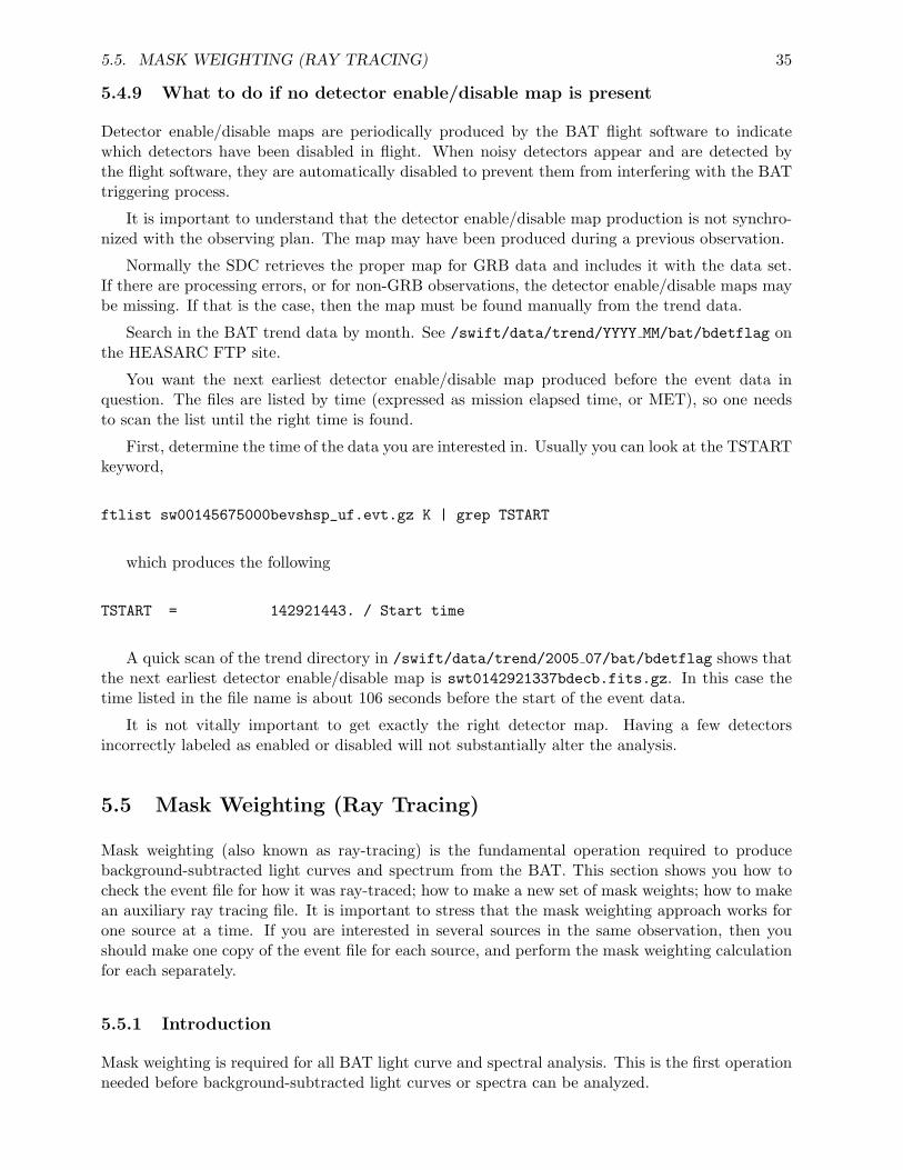
5.5. MASK WEIGHTING (RAY TRACING) 35
5.4.9 What to do if no detector enable/disable map is present
Detector enable/disable maps are periodically produced by the BAT flight software to indicatewhich detectors have been disabled in flight. When noisy detectors appear and are detected bythe flight software, they are automatically disabled to prevent them from interfering with the BATtriggering process.
It is important to understand that the detector enable/disable map production is not synchro-nized with the observing plan. The map may have been produced during a previous observation.
Normally the SDC retrieves the proper map for GRB data and includes it with the data set.If there are processing errors, or for non-GRB observations, the detector enable/disable maps maybe missing. If that is the case, then the map must be found manually from the trend data.
Search in the BAT trend data by month. See /swift/data/trend/YYYY MM/bat/bdetflag onthe HEASARC FTP site.
You want the next earliest detector enable/disable map produced before the event data inquestion. The files are listed by time (expressed as mission elapsed time, or MET), so one needsto scan the list until the right time is found.
First, determine the time of the data you are interested in. Usually you can look at the TSTARTkeyword,
ftlist sw00145675000bevshsp_uf.evt.gz K | grep TSTART
which produces the following
TSTART = 142921443. / Start time
A quick scan of the trend directory in /swift/data/trend/2005 07/bat/bdetflag shows thatthe next earliest detector enable/disable map is swt0142921337bdecb.fits.gz. In this case thetime listed in the file name is about 106 seconds before the start of the event data.
It is not vitally important to get exactly the right detector map. Having a few detectorsincorrectly labeled as enabled or disabled will not substantially alter the analysis.
5.5 Mask Weighting (Ray Tracing)
Mask weighting (also known as ray-tracing) is the fundamental operation required to producebackground-subtracted light curves and spectrum from the BAT. This section shows you how tocheck the event file for how it was ray-traced; how to make a new set of mask weights; how to makean auxiliary ray tracing file. It is important to stress that the mask weighting approach works forone source at a time. If you are interested in several sources in the same observation, then youshould make one copy of the event file for each source, and perform the mask weighting calculationfor each separately.
5.5.1 Introduction
Mask weighting is required for all BAT light curve and spectral analysis. This is the first operationneeded before background-subtracted light curves or spectra can be analyzed.
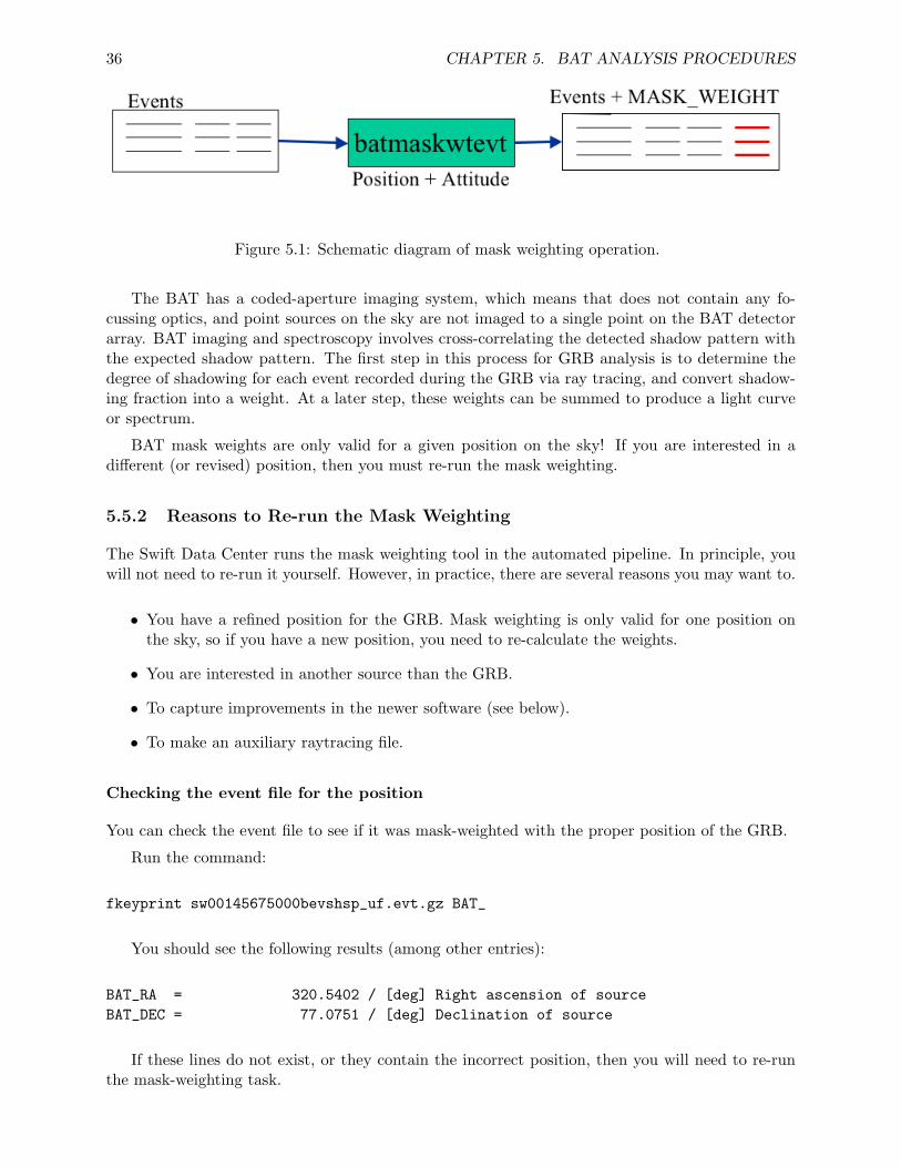
36 CHAPTER 5. BAT ANALYSIS PROCEDURES
Figure 5.1: Schematic diagram of mask weighting operation.
The BAT has a coded-aperture imaging system, which means that does not contain any fo-cussing optics, and point sources on the sky are not imaged to a single point on the BAT detectorarray. BAT imaging and spectroscopy involves cross-correlating the detected shadow pattern withthe expected shadow pattern. The first step in this process for GRB analysis is to determine thedegree of shadowing for each event recorded during the GRB via ray tracing, and convert shadow-ing fraction into a weight. At a later step, these weights can be summed to produce a light curveor spectrum.
BAT mask weights are only valid for a given position on the sky! If you are interested in adifferent (or revised) position, then you must re-run the mask weighting.
5.5.2 Reasons to Re-run the Mask Weighting
The Swift Data Center runs the mask weighting tool in the automated pipeline. In principle, youwill not need to re-run it yourself. However, in practice, there are several reasons you may want to.
• You have a refined position for the GRB. Mask weighting is only valid for one position onthe sky, so if you have a new position, you need to re-calculate the weights.
• You are interested in another source than the GRB.
• To capture improvements in the newer software (see below).
• To make an auxiliary raytracing file.
Checking the event file for the position
You can check the event file to see if it was mask-weighted with the proper position of the GRB.
Run the command:
fkeyprint sw00145675000bevshsp_uf.evt.gz BAT_
You should see the following results (among other entries):
BAT_RA = 320.5402 / [deg] Right ascension of sourceBAT_DEC = 77.0751 / [deg] Declination of source
If these lines do not exist, or they contain the incorrect position, then you will need to re-runthe mask-weighting task.
5.5. MASK WEIGHTING (RAY TRACING) 37
Checking for old software versions
The SDC has used several versions of the software throughout the mission life-time, and they arenot always the best versions. Versions of the software before HEASOFT 6.0.3 contained an errorwhich affects the flux determination of far off-axis bursts. HEASOFT 6.1.2 introduced some newfiltering techniques which should slightly improve sensitivity. You can check which version of thesoftware was used with the following command:
fkeyprint sw00145675000bevshsp_uf.evt.gz BATCREAT
You should see the following result:
# EXTENSION: 1BATCREAT= ’batmaskwtevt 1.11’ / BAT Program that modified this FITS file
If you see a version earlier than 1.11, then you should definitely re-run the mask-weighting task.If you see a version earlier than 1.16, then you might consider re-running the mask weighting task,which could gain a slight improvement in sensitivity.
What is an auxiliary raytracing file?
An auxiliary raytracing file contains information about the position of the GRB and the maskgeometry as a function of time within the BAT field of view. This information is needed to makean accurate spectral response before, during and after the spacecraft is slewing to the burst. Asof late 2005, the SDC has started to make an auxiliary raytracing file for each observation. Beforethat time, the file will not be present, and you will need to re-run the mask-weighting tool in orderto produce one.
5.5.3 Prerequisites
We will practice the mask weighting on GRB 050713A (obsid 00145675 000).
Here is what is needed:
• Known position of the GRB (RA and Dec)
• Attitude file (obsid/aux/swNNNNNNNNNNNsat.fits.gz)
• BAT event data (in obsid/bat/event/swNNNNNNNNNNNbevshsp uf.evt.gz);
• BAT quality map (in obsid/bat/hk/swNNNNNNNNNNNbcbdq.hk.gz)
In this case, let us enter the revised position as reported by Castro-Tirado (GCN 3584):RA=320.5397083, Dec=+77.074861, and apply the mask weighting operation to the original eventlist.
5.5.4 Initial Steps
Change directories to the location of the event data.
38 CHAPTER 5. BAT ANALYSIS PROCEDURES
cd 00145675000/bat/event
If the event file is compressed, unzip it. The mask-weighting task modifies the event file inplace, and gzipped files cannot be modified.
gunzip sw*.evt.gz
5.5.5 Compute Mask Weights for BAT Events
The mask-weighting task for events is called ‘batmaskwtevt’. Here is an example run,
batmaskwtevt infile=sw00145675000bevshsp_uf.evt \attitude=../../auxil/sw00145675000sat.fits.gz \ra=320.5397083 dec=+77.074861 \detmask=../hk/sw00145675000bcbdq.hk.gz \rebalance=YES corrections=default \auxfile=/local/data/gcn5b/craigm/sw00145675000bevtr.fits clobber=YES
• infile gives the event file name
• attitude gives the attitude file name
• ra and dec give the revised sky position of the GRB (see above)
• detmask is a quality filter which excludes disabled and noisy detectors; this is important sothan an accurate accounting of the number of illuminated detectors can be computed
• rebalance=YES means that the resulting light curves will be background-subtracted
• corrections=default applies the default corrections to the mask weights
• auxfile gives the output auxiliary raytracing file, to be used for spectral analysis
This analysis may take some time (several minutes), as each event needs to be ray-traced. Thespeed of the task depends on the number of slews that occur during the observation (i.e. moreslews require more intensive calculations).
5.6 Light Curve from Event Data
This section describes how to generate a light curve from BAT event data. Later sub-sectionsdescribe how to make a light curve with custom time binning.
Figure 5.2 shows schematically how light curves are created using the batbinevt task. The sametask is used to create spectra and detector plane images and detector plane histograms.
5.6.1 Prerequisites
• BAT event data (in obsid/bat/event/swNNNNNNNNNNNbevshsp uf.evt.gz);
• BAT quality map (in obsid/bat/hk/swNNNNNNNNNNNbcbdq.hk.gz).
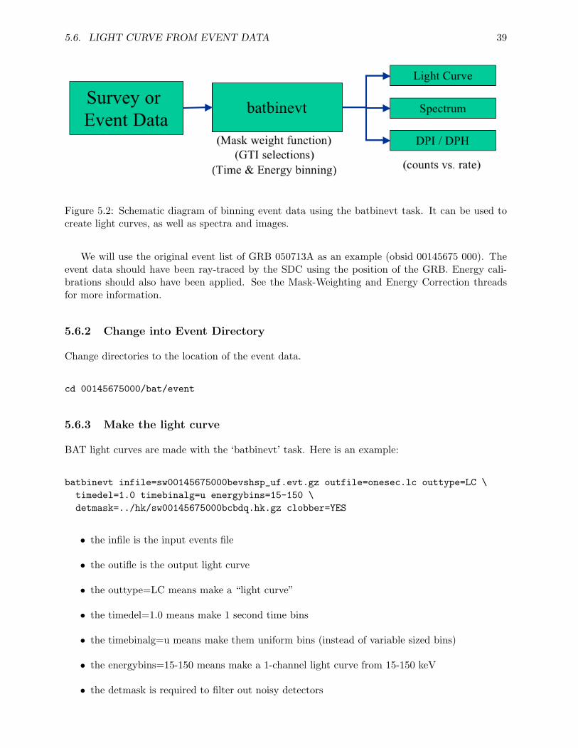
5.6. LIGHT CURVE FROM EVENT DATA 39
Figure 5.2: Schematic diagram of binning event data using the batbinevt task. It can be used tocreate light curves, as well as spectra and images.
We will use the original event list of GRB 050713A as an example (obsid 00145675 000). Theevent data should have been ray-traced by the SDC using the position of the GRB. Energy cali-brations should also have been applied. See the Mask-Weighting and Energy Correction threadsfor more information.
5.6.2 Change into Event Directory
Change directories to the location of the event data.
cd 00145675000/bat/event
5.6.3 Make the light curve
BAT light curves are made with the ‘batbinevt’ task. Here is an example:
batbinevt infile=sw00145675000bevshsp_uf.evt.gz outfile=onesec.lc outtype=LC \timedel=1.0 timebinalg=u energybins=15-150 \detmask=../hk/sw00145675000bcbdq.hk.gz clobber=YES
• the infile is the input events file
• the outifle is the output light curve
• the outtype=LC means make a “light curve”
• the timedel=1.0 means make 1 second time bins
• the timebinalg=u means make them uniform bins (instead of variable sized bins)
• the energybins=15-150 means make a 1-channel light curve from 15-150 keV
• the detmask is required to filter out noisy detectors
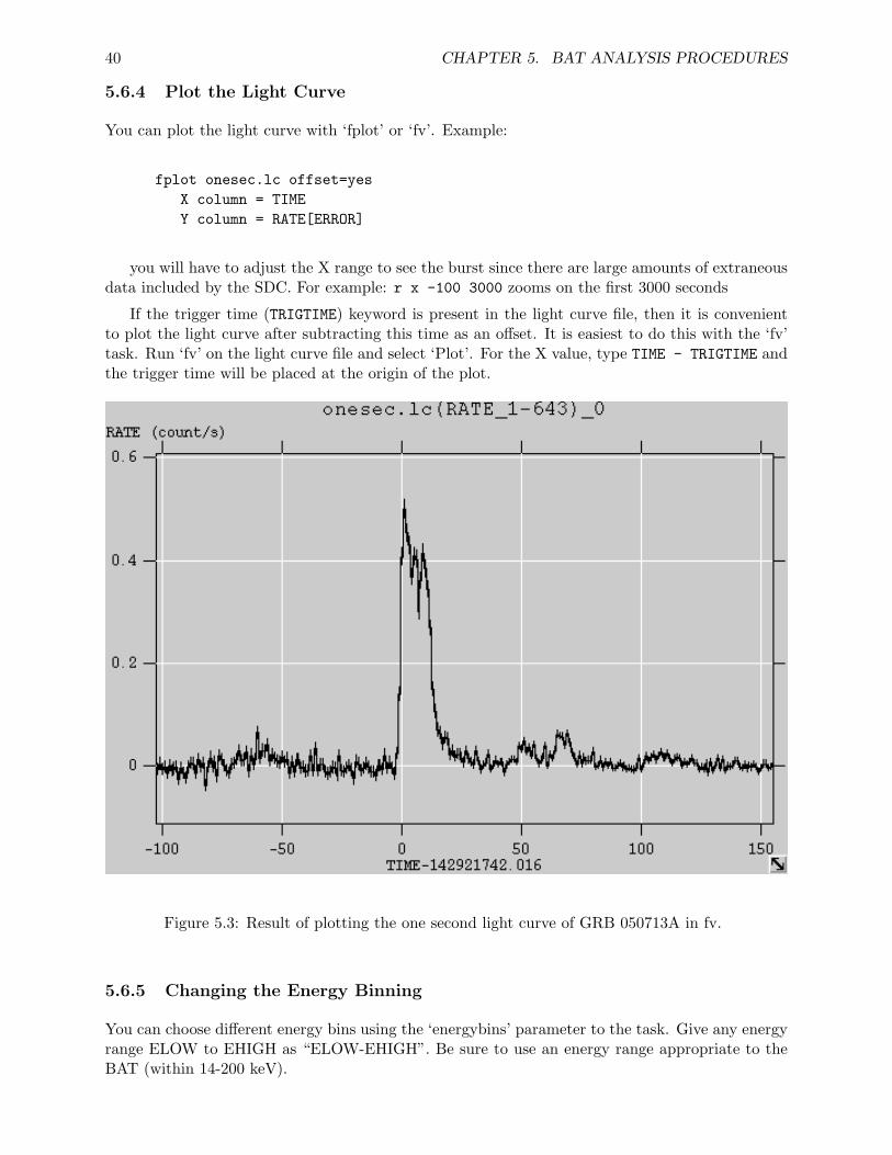
40 CHAPTER 5. BAT ANALYSIS PROCEDURES
5.6.4 Plot the Light Curve
You can plot the light curve with ‘fplot’ or ‘fv’. Example:
fplot onesec.lc offset=yesX column = TIMEY column = RATE[ERROR]
you will have to adjust the X range to see the burst since there are large amounts of extraneousdata included by the SDC. For example: r x -100 3000 zooms on the first 3000 seconds
If the trigger time (TRIGTIME) keyword is present in the light curve file, then it is convenientto plot the light curve after subtracting this time as an offset. It is easiest to do this with the ‘fv’task. Run ‘fv’ on the light curve file and select ‘Plot’. For the X value, type TIME - TRIGTIME andthe trigger time will be placed at the origin of the plot.
Figure 5.3: Result of plotting the one second light curve of GRB 050713A in fv.
5.6.5 Changing the Energy Binning
You can choose different energy bins using the ‘energybins’ parameter to the task. Give any energyrange ELOW to EHIGH as “ELOW-EHIGH”. Be sure to use an energy range appropriate to theBAT (within 14-200 keV).
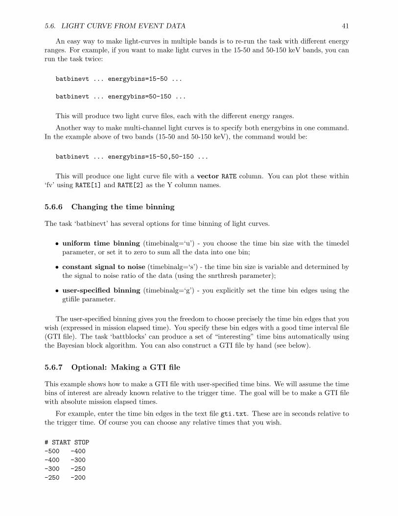
5.6. LIGHT CURVE FROM EVENT DATA 41
An easy way to make light-curves in multiple bands is to re-run the task with different energyranges. For example, if you want to make light curves in the 15-50 and 50-150 keV bands, you canrun the task twice:
batbinevt ... energybins=15-50 ...
batbinevt ... energybins=50-150 ...
This will produce two light curve files, each with the different energy ranges.
Another way to make multi-channel light curves is to specify both energybins in one command.In the example above of two bands (15-50 and 50-150 keV), the command would be:
batbinevt ... energybins=15-50,50-150 ...
This will produce one light curve file with a vector RATE column. You can plot these within‘fv’ using RATE[1] and RATE[2] as the Y column names.
5.6.6 Changing the time binning
The task ‘batbinevt’ has several options for time binning of light curves.
• uniform time binning (timebinalg=‘u’) - you choose the time bin size with the timedelparameter, or set it to zero to sum all the data into one bin;
• constant signal to noise (timebinalg=‘s’) - the time bin size is variable and determined bythe signal to noise ratio of the data (using the snrthresh parameter);
• user-specified binning (timebinalg=‘g’) - you explicitly set the time bin edges using thegtifile parameter.
The user-specified binning gives you the freedom to choose precisely the time bin edges that youwish (expressed in mission elapsed time). You specify these bin edges with a good time interval file(GTI file). The task ‘battblocks’ can produce a set of “interesting” time bins automatically usingthe Bayesian block algorithm. You can also construct a GTI file by hand (see below).
5.6.7 Optional: Making a GTI file
This example shows how to make a GTI file with user-specified time bins. We will assume the timebins of interest are already known relative to the trigger time. The goal will be to make a GTI filewith absolute mission elapsed times.
For example, enter the time bin edges in the text file gti.txt. These are in seconds relative tothe trigger time. Of course you can choose any relative times that you wish.
# START STOP-500 -400-400 -300-300 -250-250 -200
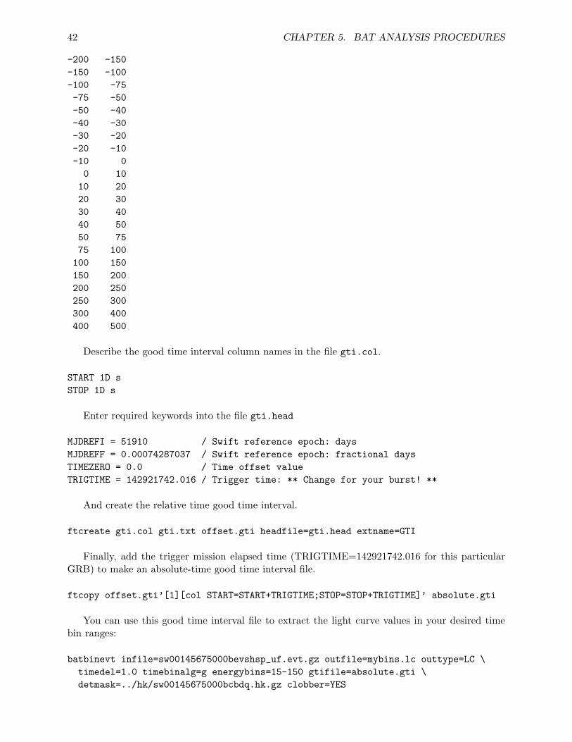
42 CHAPTER 5. BAT ANALYSIS PROCEDURES
-200 -150-150 -100-100 -75-75 -50-50 -40-40 -30-30 -20-20 -10-10 0
0 1010 2020 3030 4040 5050 7575 100100 150150 200200 250250 300300 400400 500
Describe the good time interval column names in the file gti.col.
START 1D sSTOP 1D s
Enter required keywords into the file gti.head
MJDREFI = 51910 / Swift reference epoch: daysMJDREFF = 0.00074287037 / Swift reference epoch: fractional daysTIMEZERO = 0.0 / Time offset valueTRIGTIME = 142921742.016 / Trigger time: ** Change for your burst! **
And create the relative time good time interval.
ftcreate gti.col gti.txt offset.gti headfile=gti.head extname=GTI
Finally, add the trigger mission elapsed time (TRIGTIME=142921742.016 for this particularGRB) to make an absolute-time good time interval file.
ftcopy offset.gti’[1][col START=START+TRIGTIME;STOP=STOP+TRIGTIME]’ absolute.gti
You can use this good time interval file to extract the light curve values in your desired timebin ranges:
batbinevt infile=sw00145675000bevshsp_uf.evt.gz outfile=mybins.lc outtype=LC \timedel=1.0 timebinalg=g energybins=15-150 gtifile=absolute.gti \detmask=../hk/sw00145675000bcbdq.hk.gz clobber=YES
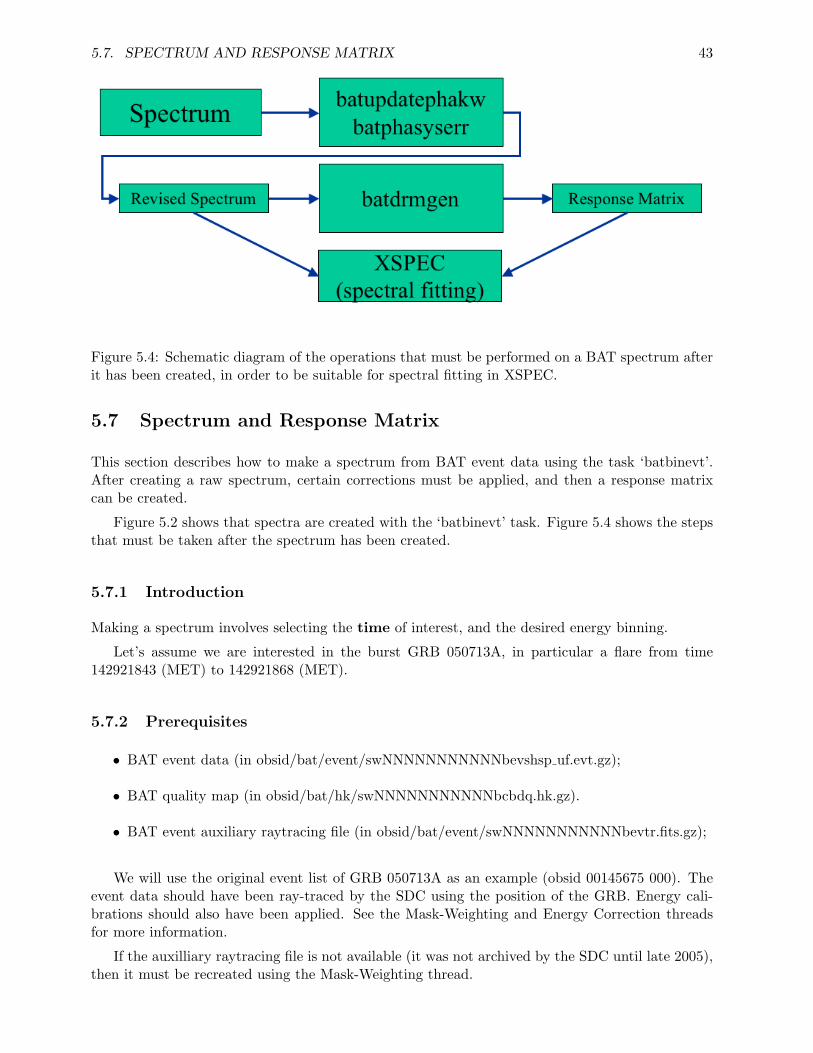
5.7. SPECTRUM AND RESPONSE MATRIX 43
Figure 5.4: Schematic diagram of the operations that must be performed on a BAT spectrum afterit has been created, in order to be suitable for spectral fitting in XSPEC.
5.7 Spectrum and Response Matrix
This section describes how to make a spectrum from BAT event data using the task ‘batbinevt’.After creating a raw spectrum, certain corrections must be applied, and then a response matrixcan be created.
Figure 5.2 shows that spectra are created with the ‘batbinevt’ task. Figure 5.4 shows the stepsthat must be taken after the spectrum has been created.
5.7.1 Introduction
Making a spectrum involves selecting the time of interest, and the desired energy binning.
Let’s assume we are interested in the burst GRB 050713A, in particular a flare from time142921843 (MET) to 142921868 (MET).
5.7.2 Prerequisites
• BAT event data (in obsid/bat/event/swNNNNNNNNNNNbevshsp uf.evt.gz);
• BAT quality map (in obsid/bat/hk/swNNNNNNNNNNNbcbdq.hk.gz).
• BAT event auxiliary raytracing file (in obsid/bat/event/swNNNNNNNNNNNbevtr.fits.gz);
We will use the original event list of GRB 050713A as an example (obsid 00145675 000). Theevent data should have been ray-traced by the SDC using the position of the GRB. Energy cali-brations should also have been applied. See the Mask-Weighting and Energy Correction threadsfor more information.
If the auxilliary raytracing file is not available (it was not archived by the SDC until late 2005),then it must be recreated using the Mask-Weighting thread.
44 CHAPTER 5. BAT ANALYSIS PROCEDURES
5.7.3 Change into Event Directory
Change directories to the location of the event data.
cd 00145675000/bat/event
5.7.4 Make the spectrum
BAT spectra are made with the ‘batbinevt’ task. Here is an example for the flare discussed above:
batbinevt infile=sw00145675000bevshsp_uf.evt.gz outfile=flare.pha outtype=PHA \timedel=0.0 timebinalg=u tstart=142921843 tstop=142921868 \energybins=CALDB:80 outunits=RATE \detmask=../hk/sw00145675000bcbdq.hk.gz clobber=YES
• the outtype=PHA means make a “spectrum” (PHA = pulse height analyzer)
• the timedel=0.00 means accumulate all the data in the specified time range into one spectrum
• the timebinalg=u means make them uniform bins (really “don’t care” in this case)
• the tstart and tstop give the start and stop time of the spectrum as discussed above
• the energybins=CALDB:80 means make a default 80-channel spectrum
• the outunits=RATE makes a rate spectrum, which is usually required since BAT spectrahave fractional counts, which XSPEC does not accept
• the detmask is required to filter out noisy detectors
5.7.5 Apply Corrections to the Spectrum
There are several corrections that need to be applied to a spectrum before it can be fit by XSPEC.The first correction involves inserting the proper ray-tracing keywords into the file.
Several geometric parameters are required to make an accurate response matrix, such as theposition of the burst in instrument coordinates. Because the spacecraft is often slewing duringthe burst, it is not possible to know for sure what those geometric parameters should be untilthe desired spectrum has been created. The ‘batupdatephakw’ task does this for you, using theauxiliary ray-tracing file described above. If the auxiliary raytracing file does not exist in yourobservation, then you will have to create it using the Mask-Weighting thread. If you do not applythis correction, then fluxes may be in error by up to 50%, and power law indices may be off by upto 0.5.
batupdatephakw flare.pha sw00145675000bevtr.fits.gz
Next, you should apply the BAT-recommended systematic error to your spectrum. The ‘bat-phasyserr’ task is used to do this, and the error vector is stored in the calibration database.
batphasyserr flare.pha CALDB
5.7. SPECTRUM AND RESPONSE MATRIX 45
5.7.6 Generate a Response Matrix
A response matrix should be created for each spectrum where the GRB is at a different position inthe BAT field of view. For example, one response matrix should be made for data taken before anyslew, and one after any slew. Any spectra made during the slew should have their own responsematrix.
batdrmgen flare.pha flare.rsp NONE
5.7.7 Important: Spectrum of a Source During a Slew
It is often the case that a gamma-ray burst source is moving in the BAT field of view. This isbecause the spacecraft often slews to the position of the GRB before the burst emission is has ended.The BAT spectral response changes with position, so you should not use one response matrix forthe entire burst. For a source with a power law spectrum, a position error of 25 degrees introducesan error of about 0.1 in the photon index, and about 10% in total flux. The spectral distortioneffect will be more pronounced if the slew is a longer distance, or if the GRB has strong emissionpeaks separated by a large time and/or distance. The distortion will be less if the GRB emissionoccurs mostly during a pointing, and of course there will be no distortion if the burst emission iscompletely confined to a pointing.
You should break long bursts which overlap slews into smaller segments corresponding towhether the spacecraft is moving or not. Generally speaking, you should make a response ma-trix whenever the position of the source changes by more than 15 degrees (or smaller incrementsif you wish). One straightforward way to do this is to use the position columns in the auxiliaryray tracing file. Look for the columns named IMX and IMY, which contain the source position inthe BAT field of view, relative to the spacecraft pointing direction. The values are tangent planecoordinates, so tan(15 deg) ∼ 0.27. Thus, you should break a spectrum into segments where thesource moves no more than 0.25 in the IMX or IMY coordinate.
The SDC should make “pre-slew” and “post-slew” response matrices. These generally shouldcorrespond to the pointings during the BAT trigger, and the following pointing after the slew,respectively. These matrices will be useful if the burst primarily overlaps either the pre-slew orpost-slew pointings.
5.7.8 Analyze Spectrum in XSPEC
You can now load this spectrum within the spectral fitting program XSPEC. Please be aware thatyou should ignore data below 14 keV and above 195 keV. Since the BAT mask becomes transparentaround 150 keV, the BAT team recommends fitting spectra in the 15-150 keV range.
Common Spectral Models
The following models are commonly used in fitting of BAT spectra.
powerlaw/pegpwrlw The simplest model. Powerlaw is normalized by its differential spectrum,and pegpwrlw is normalized by total flux. NOTE: since the powerlaw model is normalized at1 keV, it can lead to spurious statistical correlations between parameters in the BAT 15-150keV band; pegpwrlw is preferred.
46 CHAPTER 5. BAT ANALYSIS PROCEDURES
cutoffpl Power law with an exponential cut-off at high energies. As with the simple power lawmodel, cutoffpl is normalized at 1 keV.
grbm “Band” gamma-ray burst model. Typically BAT spectra do not cover a large enough energyrange to uniquely determine all Band model parameters. NOTE: “tem” parameter in “grbm”model is a cutoff energy instead of Epeak. Epeak is calculated with the following way; Epeak= (2+alpha)*tem.
The BAT team uses the following custom cut-off power law model in XSPEC:
mdefine cutep50 (E/50.0)**(-a)*exp(-E*(2.0-a)/b)
where the parameters are:
a photon index
b Epeak [keV]
the advantages to this model are that the photon index is normalized at 50 keV, in the middleof the BAT energy band, and the Epeak parameter is the well known quantity associated withgamma-ray bursts, which can also be derived from the Band model (see above).
In comparison to the standard cut-off power law model (cutoffpl), the photon index is iden-tical, and the relation between Epeak and HighECut is,
Epeak = (2-PhoIndex)*HighECut
where HighECut is the exponential cut-off energy of XSPEC.
Typically, the BAT team prefers the custom cut-off power law fit if the chi-squared valueimproves by more than 6 over the pure power law fit.
5.7.9 Choosing Different Energy Binning
You are free to choose different energy binning than the default 80-bin spectrum (the default isselected with energybins=CALDB:80).
The batbinevt task accepts either a file with an EBOUNDS extension containing bin edges, ora comma-separate list of energy bin edges.
5.7.10 Do Not Use GRPPHA
Do not group spectral bins of BAT spectra with programs like GRPPHA. The purpose of doing sofor photon counting instruments is to collect enough photons in each bin so that gaussian statisticsapply. However, BAT is not a photon counting instrument. By virtue of the mask weightingtechnique, BAT spectra already have gaussian statistics. Thus, there is no need to performinggrouping. Spectral fits with non-grouped spectra should be correct, even if the count rate in agiven bin is consistent with zero.
For low-statistics data, it may appropriate to use XSPEC’s setplot group command to makea more pleasing plot, but be aware that this command makes some statistical assumptions about“counts” in a spectrum which are not necessarily applicable to BAT spectra. It is more correct tomake a new spectrum with coarser energy binning.
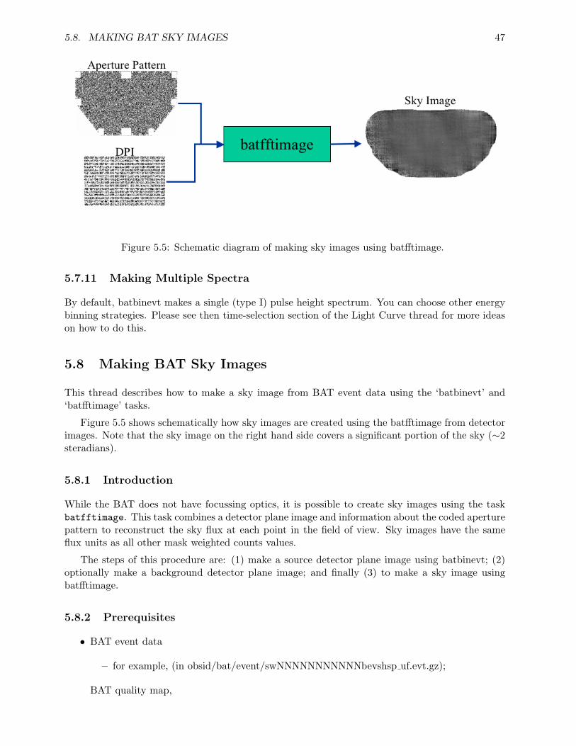
5.8. MAKING BAT SKY IMAGES 47
Figure 5.5: Schematic diagram of making sky images using batfftimage.
5.7.11 Making Multiple Spectra
By default, batbinevt makes a single (type I) pulse height spectrum. You can choose other energybinning strategies. Please see then time-selection section of the Light Curve thread for more ideason how to do this.
5.8 Making BAT Sky Images
This thread describes how to make a sky image from BAT event data using the ‘batbinevt’ and‘batfftimage’ tasks.
Figure 5.5 shows schematically how sky images are created using the batfftimage from detectorimages. Note that the sky image on the right hand side covers a significant portion of the sky (∼2steradians).
5.8.1 Introduction
While the BAT does not have focussing optics, it is possible to create sky images using the taskbatfftimage. This task combines a detector plane image and information about the coded aperturepattern to reconstruct the sky flux at each point in the field of view. Sky images have the sameflux units as all other mask weighted counts values.
The steps of this procedure are: (1) make a source detector plane image using batbinevt; (2)optionally make a background detector plane image; and finally (3) to make a sky image usingbatfftimage.
5.8.2 Prerequisites
• BAT event data
– for example, (in obsid/bat/event/swNNNNNNNNNNNbevshsp uf.evt.gz);
BAT quality map,
48 CHAPTER 5. BAT ANALYSIS PROCEDURES
– a basic map can be found in obsid/bat/hk/swNNNNNNNNNNNbcbdq.hk.gz;
– one can be created by using the “Creating a Quality Map” procedure;
Swift attitude information (in obsid/auxil/swNNNNNNNNNNNsat.fits.gz).
For example, let’s assume we are interested in the burst GRB 050713A, in particular to producean image of the “flare” from time 142921843 (MET) to 142921868 (MET).
5.8.3 Change into Event Directory
Change directories to the location of the event data.
cd 00145675000/bat/event
5.8.4 Make a Detector Plane Image
A Detector Plane Image (DPI) is a map of the counts (or count rate) in each detector as it is layedout geographically in the detector plane. This map is the input to the deconvolution software.
Issue the following command,
batbinevt infile=sw00145675000bevshsp_uf.evt.gz outfile=flare.dpi outtype=DPI \timedel=0.0 timebinalg=u tstart=142921843 tstop=142921868 \energybins=14-150 outunits=RATE weighted=NO ecol=ENERGY \detmask=../hk/sw00145675000bcbdq.hk.gz clobber=YES
where
• outtype=DPI means to make a DPI
• timedel=0.0 means accumulate all the data into one single DPI
• timeginalg=u means make them uniform time bins (really “don’t care” in this case)
• the tstart and tstop give the start and stop time of the spectrum as discussed above
• the energybins=14-150 means make a single image in the 14-150 keV range
• the ecol=ENERGY means use the ENERGY column for energy selections
• the outunits=RATE makes a rate image
• the weighted=NO means do not perform background subtraction
• the detmask is required to filter out noisy detectors
The result should be a single detector plane image. It is also possible to select multiple timeranges or multiple energy bands. batfftimage will automatically process these to produce sky imagesin multiple slices.
5.8. MAKING BAT SKY IMAGES 49
5.8.5 Making a Background Detector Plane Image
Making a background detector plane image is optional, but it will increase the sensitivity of theimage when bright sources are present. If possible, the background interval should be made fromdata with similar background levels and for a longer duration than the source image.
Use the same procedure as above to create a DPI file during a time range when you know thereis no source emission. Let us call that file “bkg.dpi”.
NOTE: if the background or bright sources are known to have varied significantly between thetime of the source and background DPIs, there may be little or no benefit to making a backgroundfile.
Advanced usage: if bright sources are known to be present in the image, it is possible to usethe batclean task to create a background map which removes many systematic artifacts. This isusually not necessary for images with exposures less than 100 seconds.
5.8.6 Making a Sky Image
A sky image is created from a DPI using the ‘batfftimage’ task. Issue the following command,
batfftimage infile=flare.dpi outfile=flare.img attitude=../../auxil/sw00145675000sat.fits.gz \bkgfile=bkg.dpi detmask=../hk/sw00145675000bcbdq.hk.gz clobber=YES
where
• infile is the DPI file name
• bkgfile is the background DPI file name (‘NONE’ can also be used if no background file isavailable)
• outfile is the output sky image file name
• attitude is the spacecraft attitude file name
• detmask is the detector quality map
The result is a BAT sky image. If valid spacecraft attitude data was used, then the sky imageshould automatically have celestial coordinates (WCS keywords) attached.
You may use your favorite FITS image viewer to examine the image (for example FV or DS9).
Figure 5.6 shows the appearance of a typical bright point source in a BAT sky image.
5.8.7 Caveats
The spacecraft attitude may have changed during the accumulation interval of your DPI. You mustcarefully filter out spacecraft slew data and use only steady pointed attitude information, or thecelestial coordinate system will be erroneous.
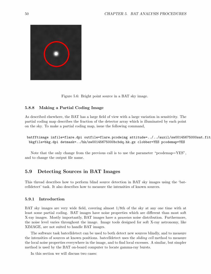
50 CHAPTER 5. BAT ANALYSIS PROCEDURES
Figure 5.6: Bright point source in a BAT sky image.
5.8.8 Making a Partial Coding Image
As described elsewhere, the BAT has a large field of view with a large variation in sensitivity. Thepartial coding map describes the fraction of the detector array which is illuminated by each pointon the sky. To make a partial coding map, issue the following command,
batfftimage infile=flare.dpi outfile=flare.pcodeimg attitude=../../auxil/sw00145675000sat.fits.gz \bkgfile=bkg.dpi detmask=../hk/sw00145675000bcbdq.hk.gz clobber=YES pcodemap=YES
Note that the only change from the previous call is to use the parameter “pcodemap=YES”,and to change the output file name.
5.9 Detecting Sources in BAT Images
This thread describes how to perform blind source detection in BAT sky images using the ‘bat-celldetect’ task. It also describes how to measure the intensities of known sources.
5.9.1 Introduction
BAT sky images are very wide field, covering almost 1/8th of the sky at any one time with atleast some partial coding. BAT images have noise properties which are different than most softX-ray images. Mostly importantly, BAT images have a gaussian noise distribution. Furthermore,the noise level varies throughout the image. Image tools designed for soft X-ray astronomy, likeXIMAGE, are not suited to handle BAT images.
The software task batcelldetect can be used to both detect new sources blindly, and to measurethe intensities of sources at known positions. batcelldetect uses the sliding cell method to measurethe local noise properties everywhere in the image, and to find local excesses. A similar, but simplermethod is used by the BAT on-board computer to locate gamma-ray bursts.
In this section we will discuss two cases:
5.9. DETECTING SOURCES IN BAT IMAGES 51
• detecting a source blindly
• detecting a source at a known position
5.9.2 Prerequisites
We will practice the operation image data from on GRB 050713A (obsid 00145675 000).
Here is what is needed:
• BAT sky image (say, preslew.img)
• partial coding map (say, preslew.pcodeimg)
For example, we use the documentation on “Making BAT Sky Images” to create sky imagesand partial coding maps. These kinds of images can also be generated using the ‘batgrbproduct’task, which creates a complete set of analysis products for a gamma-ray burst. The Swift DataCenter also makes BAT sky images as a part of its standard processing.
5.9.3 Perform Blind Source Detection
batcelldetect operates on a sky image and partial coding map to produce a catalog of detectedsources.
Issue the following command,
batcelldetect preslew.img preslew.cat 5 \pcodefile=preslew.pcodeimg regionfile=preslew.reg \clobber=YES
where
• preslew.img is the sky image
• preslew.cat is the output catalog produced by batcelldetect
• “5” is the local signal to noise detection threshold in sigma units (this should always be atleast 4)
• pcodefile is the partial coding file
• regionfile is a region file produced by batcelldetect which you can load into an image viewerlike DS9
• clobber=YES is usually recommended, since otherwise batcelldetect may attempt to appendto an existing catalog file.
The Output
The output of the task should look something like this (for the prompt pre-slew emission of thisparticular GRB):

52 CHAPTER 5. BAT ANALYSIS PROCEDURES
******************************************# batcelldetect v1.60------------------------------------------...------------------------------------------
Found 1 Images (and selected 1 images)Analyzing Image: 1Detection Iteration 1
Found 21 cumulative pixelsDetection Iteration 2
Found 21 cumulative pixels
Detected 1 sources
# RAcent DECcent POSerr Theta Phi Peak Cts SNR Name320.5664 +77.0719 0.0069 33.0 114.3 5.0688 28.2 UNKNOWN
------------------------------------------
batcelldetect works in two passes. In the first pass, it scans for groups of pixels above the noiselevel. The “Found NN cumulative pixels” messages shows that batcelldetect found some strongexcess pixels. In the second pass, batcelldetect fits a point spread function to each excess in orderto refine the position and intensity. Finally, it prints a report of the detected sources.
In this particular case, batcelldetect found one source. The “RAcent,DECcent” columns givethe best-fit position in celestial coordinates. Theta and Phi are the position in BAT instrumentalcoordinates. “Peak Cts” gives the best-fit peak intensity. The name is “UNKNOWN” because weperformed a blind search with no input catalog.
SNR gives the local signal to noise ratio for that source. In this case the signal to noise ratio is28.2, indicating a highly significant detection. Please note that the position centroid uncertaintydepends systematically on the signal to noise ratio, as documented in the BAT calibration reports.In some cases, the formal statistical centroid error will be too small. Scientists should use theguidance in the calibration reports in order to determine a more conservative position error.
The region file, called preslew.reg in this example, can be loaded into an image viewer like DS9to highly the detected sources. Highly significant sources are highlighted in green. Weak sourcesappear in blue.
The Output Catalog
While some simple diagnostic data is printed to the console, a much larger amount of information issaved in the output catalog. This file contains a detailed accounting of every image excess analyzedby batcelldetect. More information about the contents of this file can be found in the documentationfor batcelldetect.
Lowering the Threshold?
The significance threshold in the example above was “5” meaning that an excess must be at least5 sigma above the local noise level to be detected. Knowing that the single-trial probability ofdetecting a >5 sigma excess by chance is less than 10-6, users might be tempted to lower thethreshold. However, users should bear in mind that there are of order 300000 independent pixels in
5.9. DETECTING SOURCES IN BAT IMAGES 53
a typical BAT sky image, which results in about 300000 trials. Thus, the true chance probabilityof getting a >5 sigma fluctuation somewhere in the image is 10-20%. This result also means that ifyou look at enough images (say 5-10 images), you will get a >5 sigma excess just by chance. Usersshould always carefully account for the number of trials appropriately in assessing the significanceof a particular excess, and generally should never lower the threshold below 5 sigma.
5.9.4 Finding the Intensities of Known Sources
In addition to performing a blind search, batcelldetect can also measure the intensities of sourcesat known positions. No matter what the intensities are at those known positions, batcelldetect willreport them (they can even be negative, since BAT images have gaussian statistics).
Let us suppose we are worried about whether the X-ray binary 4U 0114+65 is interferingwith the measurement of the GRB. Generally speaking bright sources increase the overall noiselevel everywhere in the image by about 1% of the bright source’s intensity. Thus, a very brightsource can distort the intensity of another source. Since 4U 0114+65 is about 21 degrees from theGRB position, it is in the field of view. We can check the the intensities of both sources usingbatcelldetect.
Targeted searches are done by specifying an input catalog (or “analysis catalog”). batcelldetectexpects the input catalog to be in a certain format which is easy to create from ASCII files usinga tool like ‘ftcreate’. The catalog must be a FITS file with at least these three columns: NAME,RA OBJ, DEC OBJ. As one might expect, these are the name and position of the source.
Creating a Catalog from Scratch
Here are some simple steps to create a catalog from scratch. Remember that we are interested inthe flux at the position of 4U 0114+65, which has a known position. Let us first create a text filewith the name and position of this source source and call it ‘incat.dat’:
# Name RA_OBJ DEC_OBJ’4U 0114+65’ 19.5113 65.2918
Of course, it is straightforward to add more sources to the catalog by adding more lines to thisfile. In fact, you can use a large catalog of your favorite sources which might not even be in the fieldof view. batcelldetect automatically filters the input catalog to include only those sources whichare in the field of view of the image.
We will use the task ‘ftcreate’ to convert this to a FITS file. ftcreate needs a ’column description’file. This is an ASCII file which we will call ‘incat.col’:
NAME 30ARA_OBJ E degDEC_OBJ E deg
The three lines of the file correspond to the three columns of the FITS file.
Finally, we create the FITS catalog, ‘incat.cat’, with the following command,
ftcreate incat.col incat.dat incat.cat
54 CHAPTER 5. BAT ANALYSIS PROCEDURES
Using the Input Catalog
We can use the input catalog in a call to batcelldetect. Issue the following modified command,
batcelldetect preslew.img preslew.cat 5 \pcodefile=preslew.pcodeimg regionfile=preslew.reg \incatalog=incat.cat \clobber=YES
The command is the same as the previous one, with the addition of the input catalog that wecreated in the previous step.
The Output
The output list of sources has now changed.
# RAcent DECcent POSerr Theta Phi Peak Cts SNR Name19.5113 +65.2918 0.0000 23.7 73.5 -0.0397 -0.3 4U 0114+65
320.5664 +77.0719 0.0069 33.0 114.3 5.0688 28.2 UNKNOWN
There are two sources listed instead of one. The first source is 4U 0114+65, the source weentered in the input catalog. It has a position error of 0 since it was assumed to be fixed at itsknown position. The second source is the GRB we already detected with the previous command.
It should be obvious that with a significance of -0.3 sigma, 4U 0114+65 is not detected, andtherefore it is not interfering with the measurement of the GRB. Since 4U 0114+65 is quite weak,it will appear in DS9 as a blue circle instead of a green one.
5.9.5 Advanced Usage
batcelldetect is a complex tool with many options. Many users will be satisfied with the optionsdescribed here. Users with more advanced needs can consult the batcelldetect documentation formore detailed information.
Chapter 6
BAT Analysis Issues
6.1 Introduction
This chapter contains various science analysis issues that may come up during analysis. In somecases, the issues represent “bugs” in the software, which are usually corrected in later softwarereleases. In other cases, the issue may reflect a “gotcha” or other subtle problem that needs specialattention.
The chapter is organized into two sections. The first section contains “current” issues thatmay affect analysis of data in the archive today, using recently available software. Users shoulddefinitely consult this first section for any issues that might affect their data analysis.
The second section contains older issues that are not likely to affect present-day analysis. Thisinvolves softare bugs that have been fixed more than a year ago, Swift Data Center problems thathave been fixed, and other issues that have since been resolved.
Each issue contains vital information, such as the versions of the software and which tasks itaffects, the status of the issue, and a more complete narrative about the problem.
6.2 Current Issues
6.2.1 batoccultgti: Fails when checking the field of view only
Task: batoccultgtiVersion: 2.3 and earlierWhat builds: HEASoft 6.3.1 and earlierProblem: batoccultgti reports an error ”could not create ’’”Status: WorkaroundUpdated: 30 Jul 2007
The task batoccultgti can be used to select times when a particular source is both unoccultedby the earth, and in the field of view. There are several field of view selection criteria, includingboth partial coding and instrument coordinates such as IMX, IMY, and theta.
However, if the user selects only instrument coordinate constraints, then batoccultgti will reportthe following error:
ERROR: could not create ’’ at /path/name/...Task batoccultgti 2.3 terminating with status -1
55
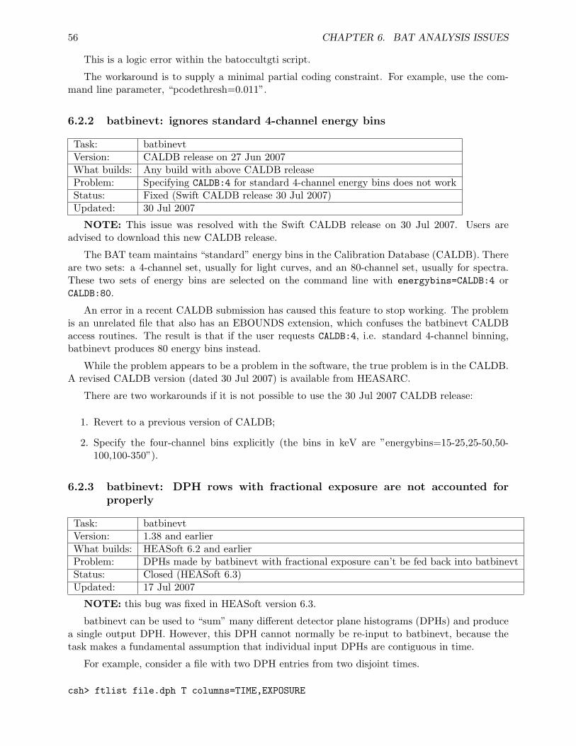
56 CHAPTER 6. BAT ANALYSIS ISSUES
This is a logic error within the batoccultgti script.
The workaround is to supply a minimal partial coding constraint. For example, use the com-mand line parameter, “pcodethresh=0.011”.
6.2.2 batbinevt: ignores standard 4-channel energy bins
Task: batbinevtVersion: CALDB release on 27 Jun 2007What builds: Any build with above CALDB releaseProblem: Specifying CALDB:4 for standard 4-channel energy bins does not workStatus: Fixed (Swift CALDB release 30 Jul 2007)Updated: 30 Jul 2007
NOTE: This issue was resolved with the Swift CALDB release on 30 Jul 2007. Users areadvised to download this new CALDB release.
The BAT team maintains “standard” energy bins in the Calibration Database (CALDB). Thereare two sets: a 4-channel set, usually for light curves, and an 80-channel set, usually for spectra.These two sets of energy bins are selected on the command line with energybins=CALDB:4 orCALDB:80.
An error in a recent CALDB submission has caused this feature to stop working. The problemis an unrelated file that also has an EBOUNDS extension, which confuses the batbinevt CALDBaccess routines. The result is that if the user requests CALDB:4, i.e. standard 4-channel binning,batbinevt produces 80 energy bins instead.
While the problem appears to be a problem in the software, the true problem is in the CALDB.A revised CALDB version (dated 30 Jul 2007) is available from HEASARC.
There are two workarounds if it is not possible to use the 30 Jul 2007 CALDB release:
1. Revert to a previous version of CALDB;
2. Specify the four-channel bins explicitly (the bins in keV are ”energybins=15-25,25-50,50-100,100-350”).
6.2.3 batbinevt: DPH rows with fractional exposure are not accounted forproperly
Task: batbinevtVersion: 1.38 and earlierWhat builds: HEASoft 6.2 and earlierProblem: DPHs made by batbinevt with fractional exposure can’t be fed back into batbinevtStatus: Closed (HEASoft 6.3)Updated: 17 Jul 2007
NOTE: this bug was fixed in HEASoft version 6.3.
batbinevt can be used to “sum” many different detector plane histograms (DPHs) and producea single output DPH. However, this DPH cannot normally be re-input to batbinevt, because thetask makes a fundamental assumption that individual input DPHs are contiguous in time.
For example, consider a file with two DPH entries from two disjoint times.
csh> ftlist file.dph T columns=TIME,EXPOSURE
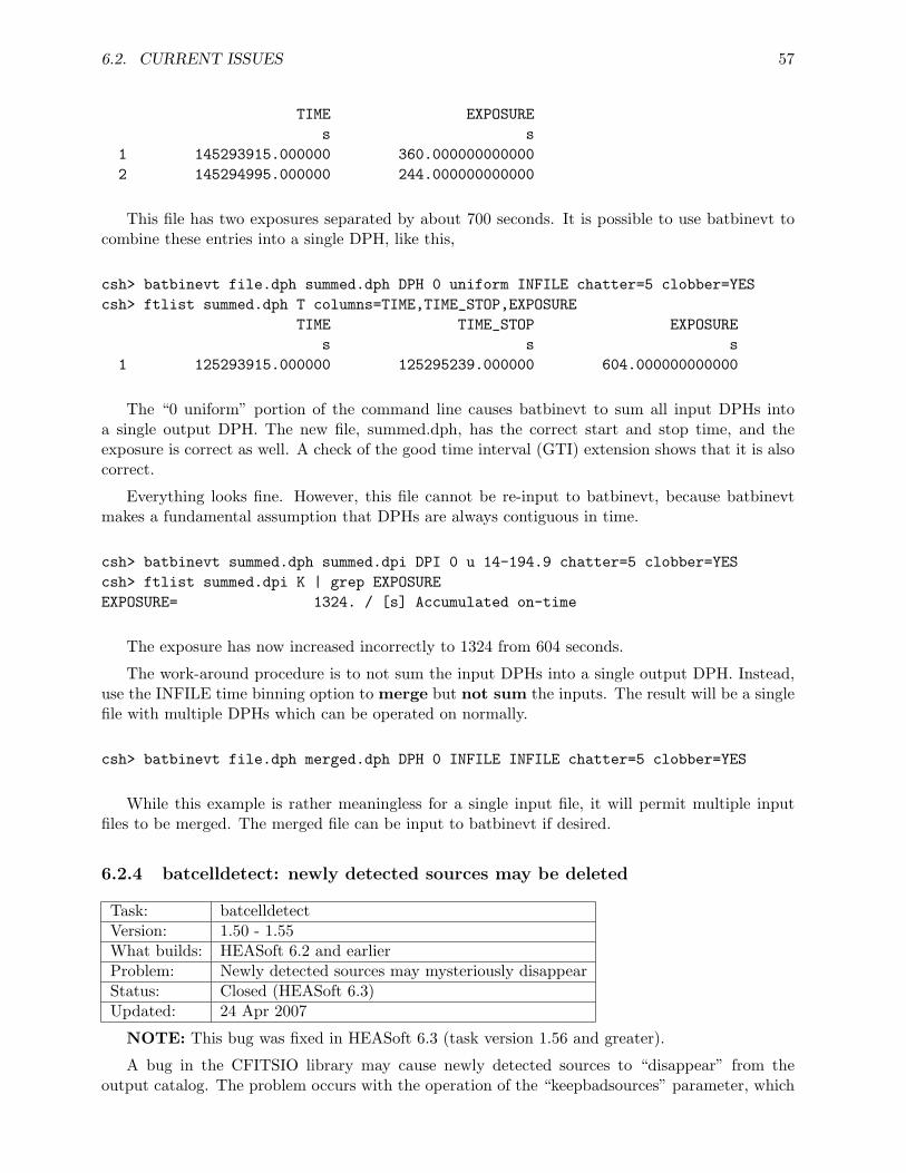
6.2. CURRENT ISSUES 57
TIME EXPOSUREs s
1 145293915.000000 360.0000000000002 145294995.000000 244.000000000000
This file has two exposures separated by about 700 seconds. It is possible to use batbinevt tocombine these entries into a single DPH, like this,
csh> batbinevt file.dph summed.dph DPH 0 uniform INFILE chatter=5 clobber=YEScsh> ftlist summed.dph T columns=TIME,TIME_STOP,EXPOSURE
TIME TIME_STOP EXPOSUREs s s
1 125293915.000000 125295239.000000 604.000000000000
The “0 uniform” portion of the command line causes batbinevt to sum all input DPHs intoa single output DPH. The new file, summed.dph, has the correct start and stop time, and theexposure is correct as well. A check of the good time interval (GTI) extension shows that it is alsocorrect.
Everything looks fine. However, this file cannot be re-input to batbinevt, because batbinevtmakes a fundamental assumption that DPHs are always contiguous in time.
csh> batbinevt summed.dph summed.dpi DPI 0 u 14-194.9 chatter=5 clobber=YEScsh> ftlist summed.dpi K | grep EXPOSUREEXPOSURE= 1324. / [s] Accumulated on-time
The exposure has now increased incorrectly to 1324 from 604 seconds.
The work-around procedure is to not sum the input DPHs into a single output DPH. Instead,use the INFILE time binning option to merge but not sum the inputs. The result will be a singlefile with multiple DPHs which can be operated on normally.
csh> batbinevt file.dph merged.dph DPH 0 INFILE INFILE chatter=5 clobber=YES
While this example is rather meaningless for a single input file, it will permit multiple inputfiles to be merged. The merged file can be input to batbinevt if desired.
6.2.4 batcelldetect: newly detected sources may be deleted
Task: batcelldetectVersion: 1.50 - 1.55What builds: HEASoft 6.2 and earlierProblem: Newly detected sources may mysteriously disappearStatus: Closed (HEASoft 6.3)Updated: 24 Apr 2007
NOTE: This bug was fixed in HEASoft 6.3 (task version 1.56 and greater).
A bug in the CFITSIO library may cause newly detected sources to “disappear” from theoutput catalog. The problem occurs with the operation of the “keepbadsources” parameter, which
58 CHAPTER 6. BAT ANALYSIS ISSUES
was added in version 1.50, and was meant to remove from the output catalog sources with badDETECT STATUS values. However, new sources were also removed by the CFITSIO libraryroutine when they shouldn’t have been.
The workaround is to set “keepbadsources=YES” and filter the output catalog manually basedon DETECT STATUS.
6.2.5 batcelldetect: the correct point spread function is gaussian
Task: batcelldetectVersion: 1.11-1.59What builds: HEASoft 6.2 and earlierProblem: Default point spread function of PYRAMID is incorrectStatus: ClosedUpdated: 17 Jul 2007
NOTE: This problem was fixed in HEASoft 6.3 (task version 1.60 and greater).
Fluxes derived from batcelldetect are based on a fit of a point spread function (PSF) to the skyimage intensities. In particular, the reported flux is the intensity at the center of the PSF. As onemight expect, the flux depends on fitting the correct PSF model to the data.
Based on a number of incorrect assumptions, the BAT team reported that the PSF was atruncated pyramidal frustum. However, this is incorrect. In fact, the PSF is very nearly a gaussianfunction (with full-width half-maximum of 22 arcmin). This PSF can be selected by using thepsfshape=GAUSSIAN option to batcelldetect (the default is psfshape=PYRAMID).
Using the incorrect frustum function will result in fluxes that are too high by 4.0% comparedto the true flux. The signal to noise ratios are high by about 3.5%. For the most part, this effectis only significant for the brightest sources, where the statistical errors are smaller than 4%.
Note that this problem applies only to fluxes from batcelldetect. It doesn’t affect mask-weightedlight curves and spectra made from batbinevt.
6.2.6 Analysis: Passive materials distort the off-axis counts/rates
Task: All flux extraction (batfftimage/batmaskwtevt/batmaskwtimg/batbinevt)Version: All versionsWhat builds: All buildsProblem: Passive materials introduce errors in mask-weighted counts/ratesStatus: Corrective Procedure (HEASoft 6.0.3)Updated: 15 Oct 2005
The BAT image system works by forming shadow patterns cast by the mask onto the detectorarray. The mask is made from lead tiles. However, the mask support structure also containssignificant absorbing materials. The edge of the support structure is a particular problem because(a) extra absorbing materials (e.g. epoxy) were applied, and (b) this material rises up above theplane of the mask. The net result is that for sensitive imaging and spectroscopy of off-axis sources,the full mask aperture cannot be used.
The BAT team has provided a new set of aperture files in CALDB, tied to the HEASoft 6.0.3release. These apertures have been reduced in size to appropriately block out the shadows of mostof the absorbing material. However, this does reduce solid angle sky coverage by 5-10%.
The aperture files are now divided into two classes:
6.2. CURRENT ISSUES 59
• FLUX - reduced aperture for sensitive flux measurements (DEFAULT)
• DETECTION - full aperture for largest solid angle and most illuminated detectors, butreduced flux accuracy
We should note that the differences between these apertures are small. The “old” DETECTIONapertures can still be used if desired, but the FLUX apertures are likely to be what most userswant, and are thus the default. The aperture type is selectable in the raytracing tasks usingaperture=CALDB:FLUX or aperture=CALDB:DETECTION.
6.2.7 batfftimage and batmaskwtimg: potentially incorrect derived attitude
Task: Imaging tasks (batfftimage and batmaskwtimg)Version: All versionsWhat Builds: All buildsProblem: Attitude may be incorrect for observation with many snapshotsStatus: Corrective ProcedureUpdated: 15 Oct 2005
Two imaging tasks assume that the spacecraft attitude is fixed during an observation: batfftim-age (to make sky images) and batmaskwtimg (to make mask weighting maps for flux extraction).Both tasks take the time at the midpoint of the observation.
If there are gaps in the observation, i.e. multiple snapshots, then it is possible, even likely, thatthe midpoint time will fall within a gap. When this happens, the attitude may be erroneouslyinterpolated.
The recommended solution is to use the ‘aspect’ tool to generate a revised attitude file. As ofHEASoft 6.0, ‘aspect’ can create a new attitude file based on the median pointing direction duringthe observation good times only. You will also need to supply a good time interval extension to‘aspect’, which should be available in the detector or sky images.
The ‘aspect’ command is:
aspect swNNNNNNNNNNNsat.fits none detimage.dpi’[STDGTI]’ newattfile=detimage.att
where swNNNNNNNNNNNsat.fits is the spacecraft attitude file, detimage.dpi is the detectorplane image (which should contain a GTI extension named STDGTI), and detimage.att is thenew attitude file valid for the detimage.dpi only.
In the future the BAT team will investigate how feasible it is to incorporate ‘aspect’-like func-tionality into the BAT imaging tools.
Updated (19 May 2005) - to recommend only the ‘aspect’ solution.Updated (15 Oct 2005) - both batfftimage and batmaskwtimg now analyze the midpoint of thetime interval
6.2.8 Analysis: Earth and Moon Occultation
Task: Flux extraction tasks (batmaskwtevt,batmaskwtimg,batfftimage)Version: All versionsWhat Builds: All buildsProblem: Earth and moon may block parts of the BAT field of viewStatus: Corrective procedureUpdated: 15 Oct 2005
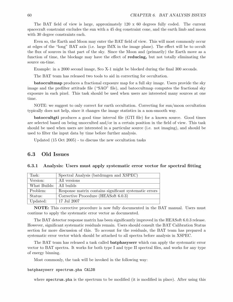
60 CHAPTER 6. BAT ANALYSIS ISSUES
The BAT field of view is large, approximately 120 x 60 degrees fully coded. The currentspacecraft constraint excludes the sun with a 45 deg constraint cone, and the earth limb and moonwith 30 degree constraints each.
Even so, the Earth and Moon may enter the BAT field of view. This will most commonly occurat edges of the “long” BAT axis (i.e. large IMX in the image plane). The effect will be to occultthe flux of sources in that part of the sky. Since the Moon and (primarily) the Earth move as afunction of time, the blockage may have the effect of reducing, but not totally eliminating thesource on-time.
Example: in a 2000 second image, Sco X-1 might be blocked during the final 300 seconds.
The BAT team has released two tools to aid in correcting for occultation.
batoccultmap produces a fractional exposure map for a full sky image. Users provide the skyimage and the prefilter attitude file (“SAO” file), and batoccultmap computes the fractional skyexposure in each pixel. This task should be used when users are interested many sources at onetime.
NOTE: we suggest to only correct for earth occultation. Correcting for sun/moon occultationtypically does not help, since it changes the image statistics in a non-smooth way.
batoccultgti produces a good time interval file (GTI file) for a known source. Good timesare selected based on being unocculted and/or in a certain position in the field of view. This taskshould be used when users are interested in a particular source (i.e. not imaging), and should beused to filter the input data by time before further analysis.
Updated (15 Oct 2005) - to discuss the new occultation tasks
6.3 Old Issues
6.3.1 Analysis: Users must apply systematic error vector for spectral fitting
Task: Spectral Analysis (batdrmgen and XSPEC)Version: All versionsWhat Builds: All buildsProblem: Response matrix contains significant systematic errorsStatus: Corrective Procedure (HEASoft 6.0.3)Updated: 17 Jul 2007
NOTE: This corrective procedure is now fully documented in the BAT manual. Users mustcontinue to apply the systematic error vector as documented.
The BAT detector response matrix has been significantly improved in the HEASoft 6.0.3 release.However, significant systematic residuals remain. Users should consult the BAT Calibration Statussection for more discussion of this. To account for the residuals, the BAT team has prepared asystematic error vector which should be attached to all spectra before analysis in XSPEC.
The BAT team has released a task called batphasyserr which can apply the systematic errorvector to BAT spectra. It works for both type I and type II spectral files, and works for any typeof energy binning.
Most commonly, the task will be invoked in the following way:
batphasyserr spectrum.pha CALDB
where spectrum.pha is the spectrum to be modified (it is modified in place). After using this
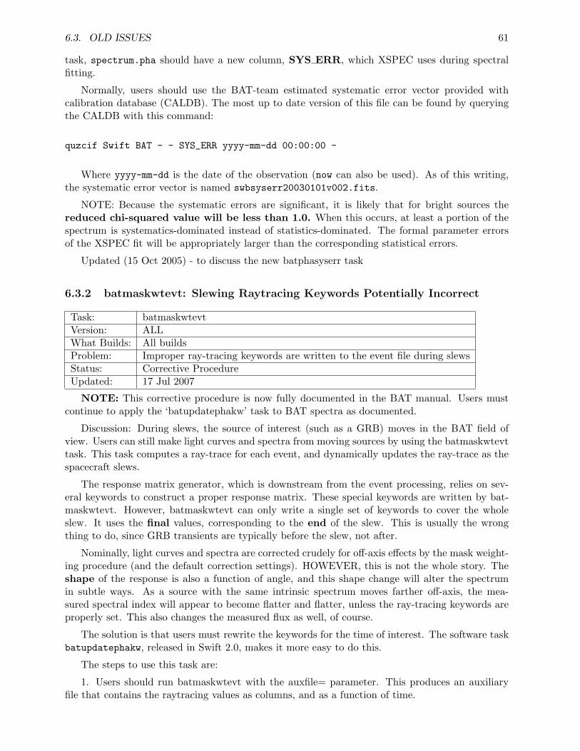
6.3. OLD ISSUES 61
task, spectrum.pha should have a new column, SYS ERR, which XSPEC uses during spectralfitting.
Normally, users should use the BAT-team estimated systematic error vector provided withcalibration database (CALDB). The most up to date version of this file can be found by queryingthe CALDB with this command:
quzcif Swift BAT - - SYS_ERR yyyy-mm-dd 00:00:00 -
Where yyyy-mm-dd is the date of the observation (now can also be used). As of this writing,the systematic error vector is named swbsyserr20030101v002.fits.
NOTE: Because the systematic errors are significant, it is likely that for bright sources thereduced chi-squared value will be less than 1.0. When this occurs, at least a portion of thespectrum is systematics-dominated instead of statistics-dominated. The formal parameter errorsof the XSPEC fit will be appropriately larger than the corresponding statistical errors.
Updated (15 Oct 2005) - to discuss the new batphasyserr task
6.3.2 batmaskwtevt: Slewing Raytracing Keywords Potentially Incorrect
Task: batmaskwtevtVersion: ALLWhat Builds: All buildsProblem: Improper ray-tracing keywords are written to the event file during slewsStatus: Corrective ProcedureUpdated: 17 Jul 2007
NOTE: This corrective procedure is now fully documented in the BAT manual. Users mustcontinue to apply the ‘batupdatephakw’ task to BAT spectra as documented.
Discussion: During slews, the source of interest (such as a GRB) moves in the BAT field ofview. Users can still make light curves and spectra from moving sources by using the batmaskwtevttask. This task computes a ray-trace for each event, and dynamically updates the ray-trace as thespacecraft slews.
The response matrix generator, which is downstream from the event processing, relies on sev-eral keywords to construct a proper response matrix. These special keywords are written by bat-maskwtevt. However, batmaskwtevt can only write a single set of keywords to cover the wholeslew. It uses the final values, corresponding to the end of the slew. This is usually the wrongthing to do, since GRB transients are typically before the slew, not after.
Nominally, light curves and spectra are corrected crudely for off-axis effects by the mask weight-ing procedure (and the default correction settings). HOWEVER, this is not the whole story. Theshape of the response is also a function of angle, and this shape change will alter the spectrumin subtle ways. As a source with the same intrinsic spectrum moves farther off-axis, the mea-sured spectral index will appear to become flatter and flatter, unless the ray-tracing keywords areproperly set. This also changes the measured flux as well, of course.
The solution is that users must rewrite the keywords for the time of interest. The software taskbatupdatephakw, released in Swift 2.0, makes it more easy to do this.
The steps to use this task are:
1. Users should run batmaskwtevt with the auxfile= parameter. This produces an auxiliaryfile that contains the raytracing values as columns, and as a function of time.
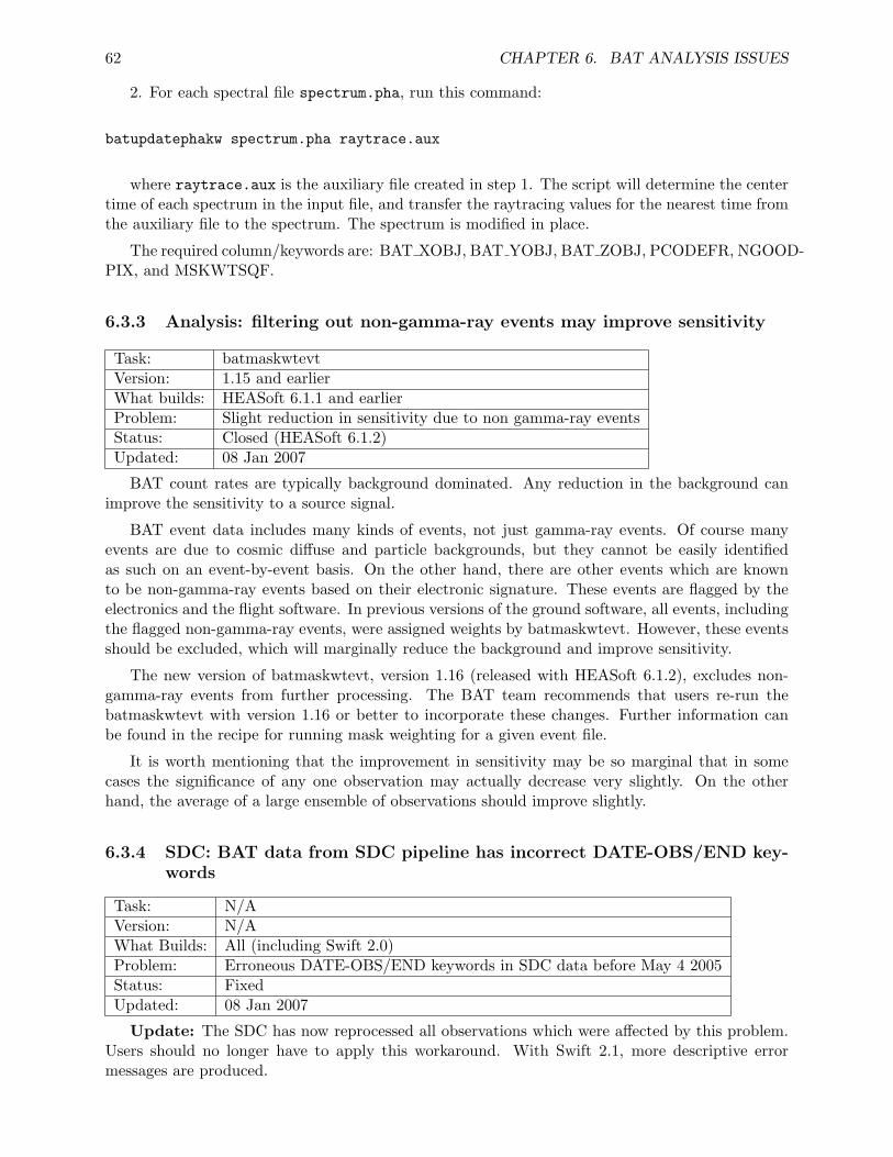
62 CHAPTER 6. BAT ANALYSIS ISSUES
2. For each spectral file spectrum.pha, run this command:
batupdatephakw spectrum.pha raytrace.aux
where raytrace.aux is the auxiliary file created in step 1. The script will determine the centertime of each spectrum in the input file, and transfer the raytracing values for the nearest time fromthe auxiliary file to the spectrum. The spectrum is modified in place.
The required column/keywords are: BAT XOBJ, BAT YOBJ, BAT ZOBJ, PCODEFR, NGOOD-PIX, and MSKWTSQF.
6.3.3 Analysis: filtering out non-gamma-ray events may improve sensitivity
Task: batmaskwtevtVersion: 1.15 and earlierWhat builds: HEASoft 6.1.1 and earlierProblem: Slight reduction in sensitivity due to non gamma-ray eventsStatus: Closed (HEASoft 6.1.2)Updated: 08 Jan 2007
BAT count rates are typically background dominated. Any reduction in the background canimprove the sensitivity to a source signal.
BAT event data includes many kinds of events, not just gamma-ray events. Of course manyevents are due to cosmic diffuse and particle backgrounds, but they cannot be easily identifiedas such on an event-by-event basis. On the other hand, there are other events which are knownto be non-gamma-ray events based on their electronic signature. These events are flagged by theelectronics and the flight software. In previous versions of the ground software, all events, includingthe flagged non-gamma-ray events, were assigned weights by batmaskwtevt. However, these eventsshould be excluded, which will marginally reduce the background and improve sensitivity.
The new version of batmaskwtevt, version 1.16 (released with HEASoft 6.1.2), excludes non-gamma-ray events from further processing. The BAT team recommends that users re-run thebatmaskwtevt with version 1.16 or better to incorporate these changes. Further information canbe found in the recipe for running mask weighting for a given event file.
It is worth mentioning that the improvement in sensitivity may be so marginal that in somecases the significance of any one observation may actually decrease very slightly. On the otherhand, the average of a large ensemble of observations should improve slightly.
6.3.4 SDC: BAT data from SDC pipeline has incorrect DATE-OBS/END key-words
Task: N/AVersion: N/AWhat Builds: All (including Swift 2.0)Problem: Erroneous DATE-OBS/END keywords in SDC data before May 4 2005Status: FixedUpdated: 08 Jan 2007
Update: The SDC has now reprocessed all observations which were affected by this problem.Users should no longer have to apply this workaround. With Swift 2.1, more descriptive errormessages are produced.
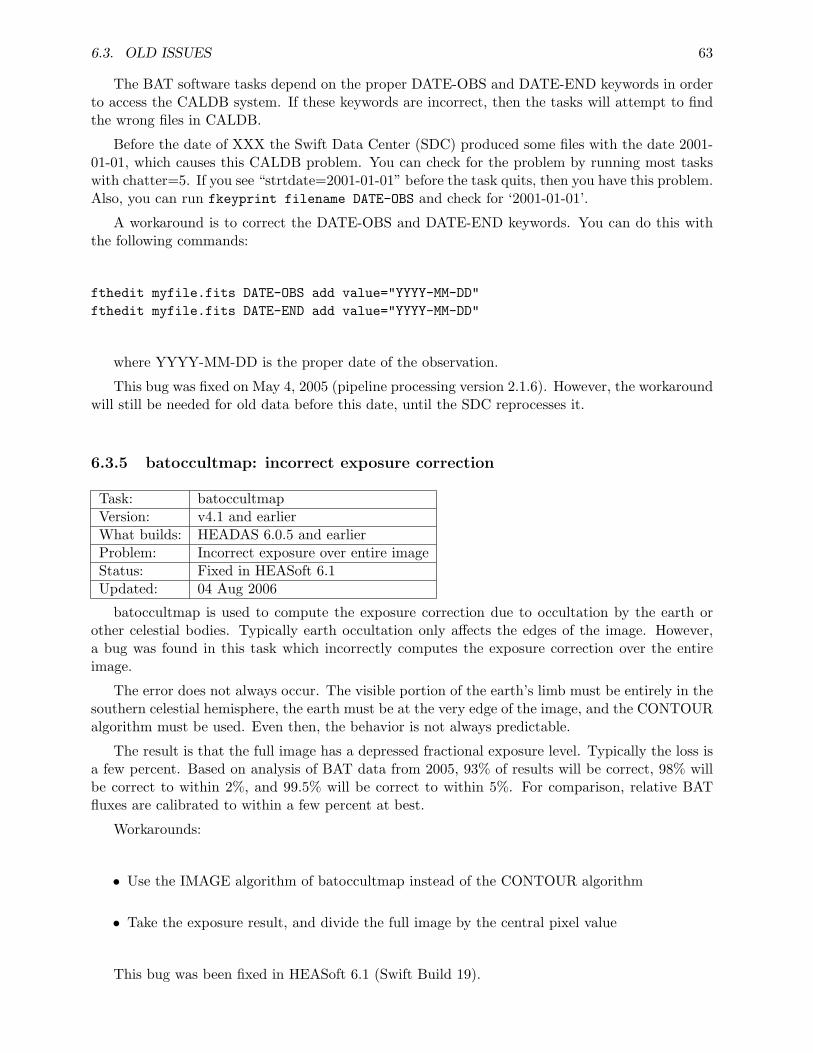
6.3. OLD ISSUES 63
The BAT software tasks depend on the proper DATE-OBS and DATE-END keywords in orderto access the CALDB system. If these keywords are incorrect, then the tasks will attempt to findthe wrong files in CALDB.
Before the date of XXX the Swift Data Center (SDC) produced some files with the date 2001-01-01, which causes this CALDB problem. You can check for the problem by running most taskswith chatter=5. If you see “strtdate=2001-01-01” before the task quits, then you have this problem.Also, you can run fkeyprint filename DATE-OBS and check for ‘2001-01-01’.
A workaround is to correct the DATE-OBS and DATE-END keywords. You can do this withthe following commands:
fthedit myfile.fits DATE-OBS add value="YYYY-MM-DD"fthedit myfile.fits DATE-END add value="YYYY-MM-DD"
where YYYY-MM-DD is the proper date of the observation.
This bug was fixed on May 4, 2005 (pipeline processing version 2.1.6). However, the workaroundwill still be needed for old data before this date, until the SDC reprocesses it.
6.3.5 batoccultmap: incorrect exposure correction
Task: batoccultmapVersion: v4.1 and earlierWhat builds: HEADAS 6.0.5 and earlierProblem: Incorrect exposure over entire imageStatus: Fixed in HEASoft 6.1Updated: 04 Aug 2006
batoccultmap is used to compute the exposure correction due to occultation by the earth orother celestial bodies. Typically earth occultation only affects the edges of the image. However,a bug was found in this task which incorrectly computes the exposure correction over the entireimage.
The error does not always occur. The visible portion of the earth’s limb must be entirely in thesouthern celestial hemisphere, the earth must be at the very edge of the image, and the CONTOURalgorithm must be used. Even then, the behavior is not always predictable.
The result is that the full image has a depressed fractional exposure level. Typically the loss isa few percent. Based on analysis of BAT data from 2005, 93% of results will be correct, 98% willbe correct to within 2%, and 99.5% will be correct to within 5%. For comparison, relative BATfluxes are calibrated to within a few percent at best.
Workarounds:
• Use the IMAGE algorithm of batoccultmap instead of the CONTOUR algorithm
• Take the exposure result, and divide the full image by the central pixel value
This bug was been fixed in HEASoft 6.1 (Swift Build 19).
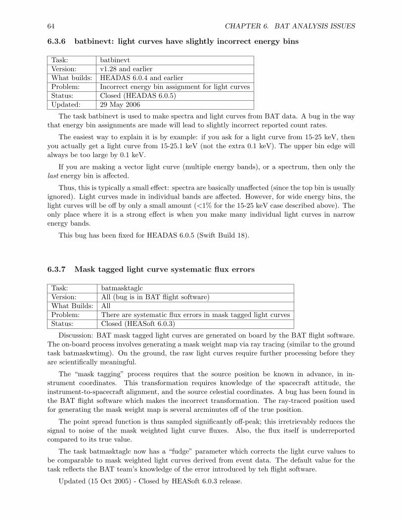
64 CHAPTER 6. BAT ANALYSIS ISSUES
6.3.6 batbinevt: light curves have slightly incorrect energy bins
Task: batbinevtVersion: v1.28 and earlierWhat builds: HEADAS 6.0.4 and earlierProblem: Incorrect energy bin assignment for light curvesStatus: Closed (HEADAS 6.0.5)Updated: 29 May 2006
The task batbinevt is used to make spectra and light curves from BAT data. A bug in the waythat energy bin assignments are made will lead to slightly incorrect reported count rates.
The easiest way to explain it is by example: if you ask for a light curve from 15-25 keV, thenyou actually get a light curve from 15-25.1 keV (not the extra 0.1 keV). The upper bin edge willalways be too large by 0.1 keV.
If you are making a vector light curve (multiple energy bands), or a spectrum, then only thelast energy bin is affected.
Thus, this is typically a small effect: spectra are basically unaffected (since the top bin is usuallyignored). Light curves made in individual bands are affected. However, for wide energy bins, thelight curves will be off by only a small amount (<1% for the 15-25 keV case described above). Theonly place where it is a strong effect is when you make many individual light curves in narrowenergy bands.
This bug has been fixed for HEADAS 6.0.5 (Swift Build 18).
6.3.7 Mask tagged light curve systematic flux errors
Task: batmasktaglcVersion: All (bug is in BAT flight software)What Builds: AllProblem: There are systematic flux errors in mask tagged light curvesStatus: Closed (HEASoft 6.0.3)
Discussion: BAT mask tagged light curves are generated on board by the BAT flight software.The on-board process involves generating a mask weight map via ray tracing (similar to the groundtask batmaskwtimg). On the ground, the raw light curves require further processing before theyare scientifically meaningful.
The “mask tagging” process requires that the source position be known in advance, in in-strument coordinates. This transformation requires knowledge of the spacecraft attitude, theinstrument-to-spacecraft alignment, and the source celestial coordinates. A bug has been found inthe BAT flight software which makes the incorrect transformation. The ray-traced position usedfor generating the mask weight map is several arcminutes off of the true position.
The point spread function is thus sampled significantly off-peak; this irretrievably reduces thesignal to noise of the mask weighted light curve fluxes. Also, the flux itself is underreportedcompared to its true value.
The task batmasktaglc now has a “fudge” parameter which corrects the light curve values tobe comparable to mask weighted light curves derived from event data. The default value for thetask reflects the BAT team’s knowledge of the error introduced by teh flight software.
Updated (15 Oct 2005) - Closed by HEASoft 6.0.3 release.
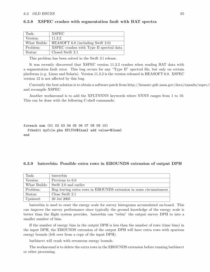
6.3. OLD ISSUES 65
6.3.8 XSPEC crashes with segmentation fault with BAT spectra
Task: XSPECVersion: 11.3.2What Builds: HEASOFT 6.0 (including Swift 2.0)Problem: XSPEC crashes with Type II spectral dataStatus: Closed Swift 2.1
This problem has been solved in the Swift 2.l release.
It was recently discovered that XSPEC version 11.3.2 crashes when reading BAT data witha segmentation fault error. This bug occurs for any “Type II” spectral file, but only on certainplatforms (e.g. Linux and Solaris). Version 11.3.2 is the version released in HEASOFT 6.0. XSPECversion 12 is not affected by this bug.
Currently the best solution is to obtain a software patch from http://heasarc.gsfc.nasa.gov/docs/xanadu/xspec/xspec11/bugs.htmland recompile XSPEC.
Another workaround is to add the XFLTNNNN keywords where NNNN ranges from 1 to 10.This can be done with the following C-shell commands:
foreach num (01 02 03 04 05 06 07 08 09 10)fthedit myfile.pha XFLT00${num} add value=${num}
end
6.3.9 baterebin: Possible extra rows in EBOUNDS extension of output DPH
Task: baterebinVersion: Previous to 6.0What Builds: Swift 2.0 and earlierProblem: Bug leaving extra rows in EBOUNDS extension in some circumstancesStatus: Close Swift 2.1Updated: 20 Jul 2005
baterebin is used to reset the energy scale for survey histograms accumulated on-board. Thiscan improve the survey performance since typically the ground knowledge of the energy scale isbetter than the flight system provides. baterebin can “rebin” the output survey DPH to into asmaller number of bins.
If the number of energy bins in the output DPH is less than the number of rows (time bins) inthe input DPH, the EBOUNDS extension of the output DPH will have extra rows with spuriousenergy bounds (left over from a copy of the input DPH).
batbinevt will crash with erroneous energy bounds.
The workaround is to delete the extra rows in the EBOUNDS extension before running batbinevtor other processing.
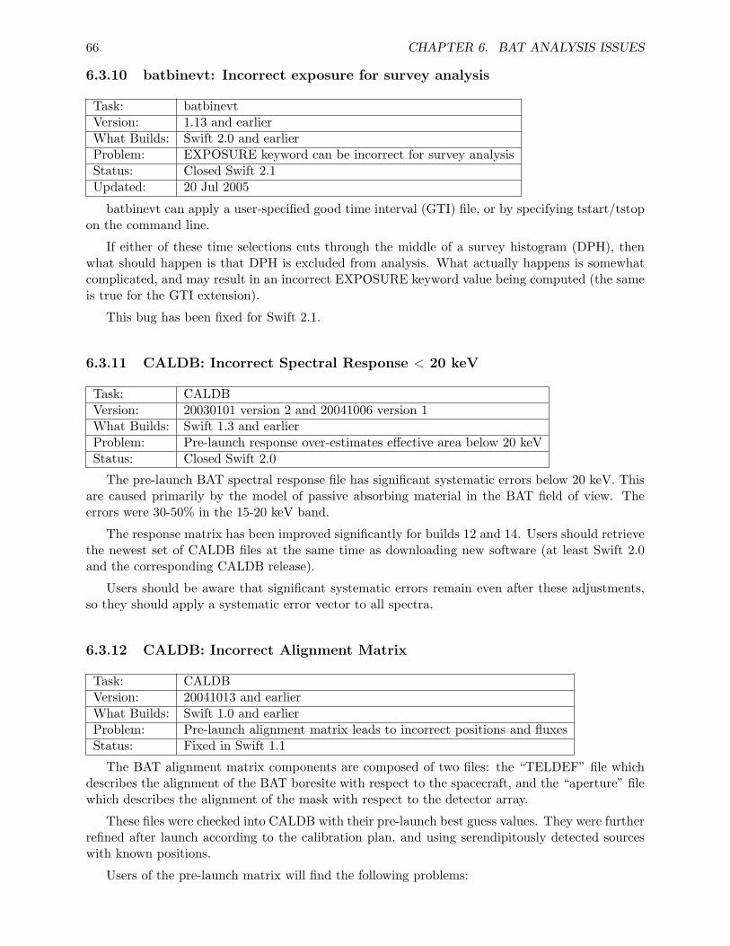
66 CHAPTER 6. BAT ANALYSIS ISSUES
6.3.10 batbinevt: Incorrect exposure for survey analysis
Task: batbinevtVersion: 1.13 and earlierWhat Builds: Swift 2.0 and earlierProblem: EXPOSURE keyword can be incorrect for survey analysisStatus: Closed Swift 2.1Updated: 20 Jul 2005
batbinevt can apply a user-specified good time interval (GTI) file, or by specifying tstart/tstopon the command line.
If either of these time selections cuts through the middle of a survey histogram (DPH), thenwhat should happen is that DPH is excluded from analysis. What actually happens is somewhatcomplicated, and may result in an incorrect EXPOSURE keyword value being computed (the sameis true for the GTI extension).
This bug has been fixed for Swift 2.1.
6.3.11 CALDB: Incorrect Spectral Response < 20 keV
Task: CALDBVersion: 20030101 version 2 and 20041006 version 1What Builds: Swift 1.3 and earlierProblem: Pre-launch response over-estimates effective area below 20 keVStatus: Closed Swift 2.0
The pre-launch BAT spectral response file has significant systematic errors below 20 keV. Thisare caused primarily by the model of passive absorbing material in the BAT field of view. Theerrors were 30-50% in the 15-20 keV band.
The response matrix has been improved significantly for builds 12 and 14. Users should retrievethe newest set of CALDB files at the same time as downloading new software (at least Swift 2.0and the corresponding CALDB release).
Users should be aware that significant systematic errors remain even after these adjustments,so they should apply a systematic error vector to all spectra.
6.3.12 CALDB: Incorrect Alignment Matrix
Task: CALDBVersion: 20041013 and earlierWhat Builds: Swift 1.0 and earlierProblem: Pre-launch alignment matrix leads to incorrect positions and fluxesStatus: Fixed in Swift 1.1
The BAT alignment matrix components are composed of two files: the “TELDEF” file whichdescribes the alignment of the BAT boresite with respect to the spacecraft, and the “aperture” filewhich describes the alignment of the mask with respect to the detector array.
These files were checked into CALDB with their pre-launch best guess values. They were furtherrefined after launch according to the calibration plan, and using serendipitously detected sourceswith known positions.
Users of the pre-launch matrix will find the following problems:
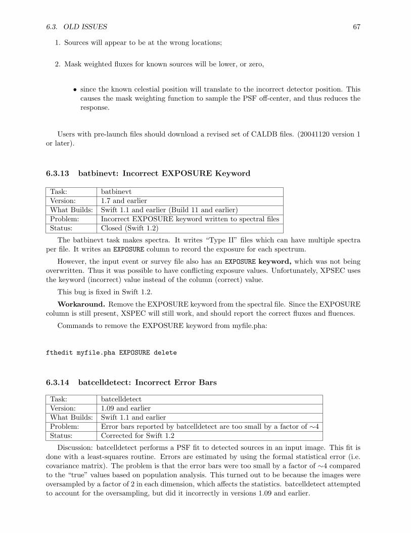
6.3. OLD ISSUES 67
1. Sources will appear to be at the wrong locations;
2. Mask weighted fluxes for known sources will be lower, or zero,
• since the known celestial position will translate to the incorrect detector position. Thiscauses the mask weighting function to sample the PSF off-center, and thus reduces theresponse.
Users with pre-launch files should download a revised set of CALDB files. (20041120 version 1or later).
6.3.13 batbinevt: Incorrect EXPOSURE Keyword
Task: batbinevtVersion: 1.7 and earlierWhat Builds: Swift 1.1 and earlier (Build 11 and earlier)Problem: Incorrect EXPOSURE keyword written to spectral filesStatus: Closed (Swift 1.2)
The batbinevt task makes spectra. It writes “Type II” files which can have multiple spectraper file. It writes an EXPOSURE column to record the exposure for each spectrum.
However, the input event or survey file also has an EXPOSURE keyword, which was not beingoverwritten. Thus it was possible to have conflicting exposure values. Unfortunately, XPSEC usesthe keyword (incorrect) value instead of the column (correct) value.
This bug is fixed in Swift 1.2.
Workaround. Remove the EXPOSURE keyword from the spectral file. Since the EXPOSUREcolumn is still present, XSPEC will still work, and should report the correct fluxes and fluences.
Commands to remove the EXPOSURE keyword from myfile.pha:
fthedit myfile.pha EXPOSURE delete
6.3.14 batcelldetect: Incorrect Error Bars
Task: batcelldetectVersion: 1.09 and earlierWhat Builds: Swift 1.1 and earlierProblem: Error bars reported by batcelldetect are too small by a factor of ∼4Status: Corrected for Swift 1.2
Discussion: batcelldetect performs a PSF fit to detected sources in an input image. This fit isdone with a least-squares routine. Errors are estimated by using the formal statistical error (i.e.covariance matrix). The problem is that the error bars were too small by a factor of ∼4 comparedto the “true” values based on population analysis. This turned out to be because the images wereoversampled by a factor of 2 in each dimension, which affects the statistics. batcelldetect attemptedto account for the oversampling, but did it incorrectly in versions 1.09 and earlier.
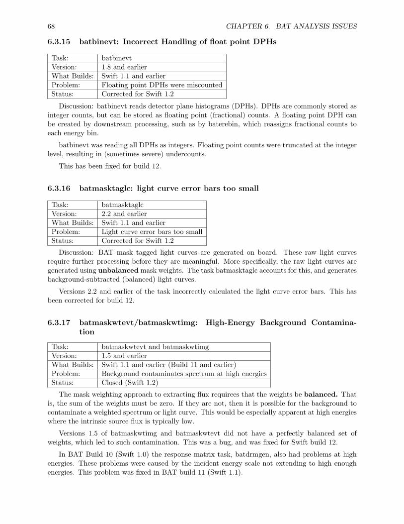
68 CHAPTER 6. BAT ANALYSIS ISSUES
6.3.15 batbinevt: Incorrect Handling of float point DPHs
Task: batbinevtVersion: 1.8 and earlierWhat Builds: Swift 1.1 and earlierProblem: Floating point DPHs were miscountedStatus: Corrected for Swift 1.2
Discussion: batbinevt reads detector plane histograms (DPHs). DPHs are commonly stored asinteger counts, but can be stored as floating point (fractional) counts. A floating point DPH canbe created by downstream processing, such as by baterebin, which reassigns fractional counts toeach energy bin.
batbinevt was reading all DPHs as integers. Floating point counts were truncated at the integerlevel, resulting in (sometimes severe) undercounts.
This has been fixed for build 12.
6.3.16 batmasktaglc: light curve error bars too small
Task: batmasktaglcVersion: 2.2 and earlierWhat Builds: Swift 1.1 and earlierProblem: Light curve error bars too smallStatus: Corrected for Swift 1.2
Discussion: BAT mask tagged light curves are generated on board. These raw light curvesrequire further processing before they are meaningful. More specifically, the raw light curves aregenerated using unbalanced mask weights. The task batmasktaglc accounts for this, and generatesbackground-subtracted (balanced) light curves.
Versions 2.2 and earlier of the task incorrectly calculated the light curve error bars. This hasbeen corrected for build 12.
6.3.17 batmaskwtevt/batmaskwtimg: High-Energy Background Contamina-tion
Task: batmaskwtevt and batmaskwtimgVersion: 1.5 and earlierWhat Builds: Swift 1.1 and earlier (Build 11 and earlier)Problem: Background contaminates spectrum at high energiesStatus: Closed (Swift 1.2)
The mask weighting approach to extracting flux requirees that the weights be balanced. Thatis, the sum of the weights must be zero. If they are not, then it is possible for the background tocontaminate a weighted spectrum or light curve. This would be especially apparent at high energieswhere the intrinsic source flux is typically low.
Versions 1.5 of batmaskwtimg and batmaskwtevt did not have a perfectly balanced set ofweights, which led to such contamination. This was a bug, and was fixed for Swift build 12.
In BAT Build 10 (Swift 1.0) the response matrix task, batdrmgen, also had problems at highenergies. These problems were caused by the incident energy scale not extending to high enoughenergies. This problem was fixed in BAT build 11 (Swift 1.1).
Appendix A
BAT Data Formats
A.1 Introduction
This Appendix provides a detailed account of the formats of BAT data. A discussion of file namingprovided; followed by descriptions of BAT science products, including event, survey and rate data;and finishing with descriptions of housekeeping and trend data products.
A.2 File Naming Overview
All BAT data products are FITS files. The Level 0 and 1 products are either FITS tables or nullfiles (header only). All files are named according to one of the following conventions (“sw” is Swiftand “b” is BAT):
sw[Observation ID][Segment Number]b[code].[suffix]
or
sw[Time stamp]b[code].[suffix]
For example, an event file for Observation ID 00074651, segment 002, would have a namesw00074651002bevtstouf.evt, where the code for event files is “evtstouf” and the suffix is “evt.”Similarly, a long trigger criteria trend file from MET 101809021 would have a name sw0101809021btblt.fits,where the code is “tblt” and suffix “fits.”
A.3 Event Files
These are time-ordered FITS tables, with each row corresponding to a single event. A fully pro-cessed event file will contain no duplicated events. Event files can be distinguished by the uniquefilename suffix “evt,” and various codes refer to different types of events and different stages inprocessing.
The columns in a fully processed event file are (EXTNAME = ‘EVENTS’):
69
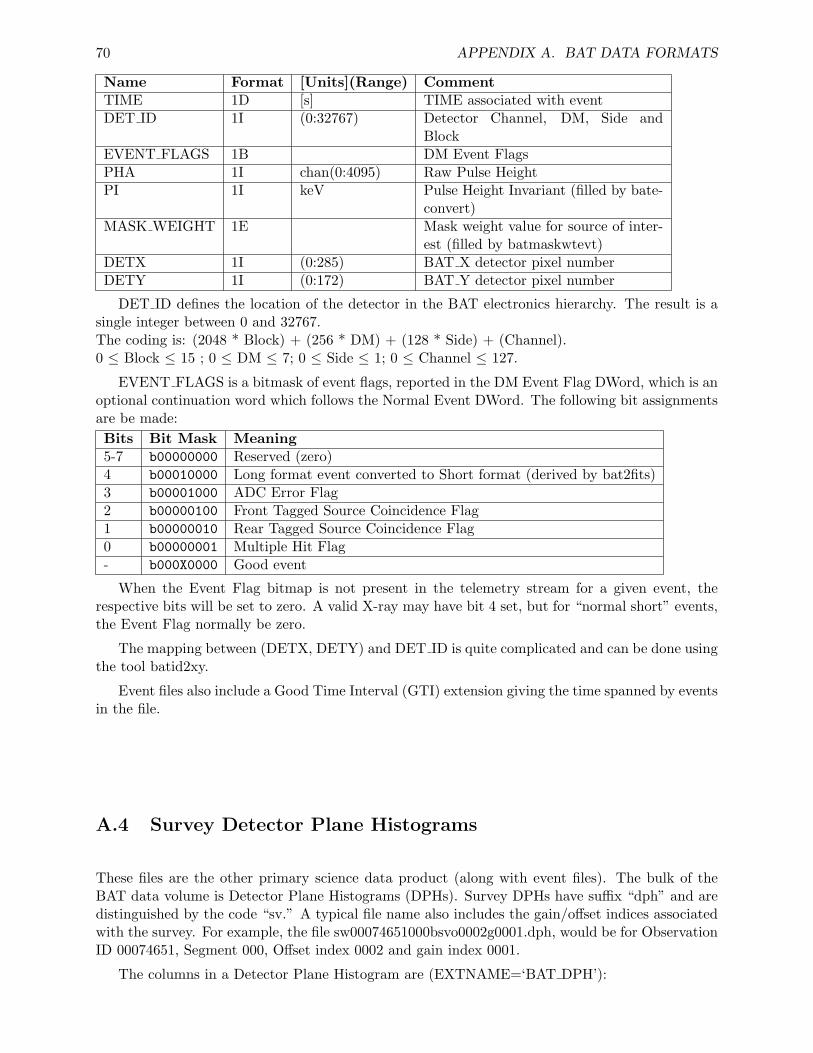
70 APPENDIX A. BAT DATA FORMATS
Name Format [Units](Range) CommentTIME 1D [s] TIME associated with eventDET ID 1I (0:32767) Detector Channel, DM, Side and
BlockEVENT FLAGS 1B DM Event FlagsPHA 1I chan(0:4095) Raw Pulse HeightPI 1I keV Pulse Height Invariant (filled by bate-
convert)MASK WEIGHT 1E Mask weight value for source of inter-
est (filled by batmaskwtevt)DETX 1I (0:285) BAT X detector pixel numberDETY 1I (0:172) BAT Y detector pixel number
DET ID defines the location of the detector in the BAT electronics hierarchy. The result is asingle integer between 0 and 32767.The coding is: (2048 * Block) + (256 * DM) + (128 * Side) + (Channel).0 ≤ Block ≤ 15 ; 0 ≤ DM ≤ 7; 0 ≤ Side ≤ 1; 0 ≤ Channel ≤ 127.
EVENT FLAGS is a bitmask of event flags, reported in the DM Event Flag DWord, which is anoptional continuation word which follows the Normal Event DWord. The following bit assignmentsare be made:Bits Bit Mask Meaning5-7 b00000000 Reserved (zero)4 b00010000 Long format event converted to Short format (derived by bat2fits)3 b00001000 ADC Error Flag2 b00000100 Front Tagged Source Coincidence Flag1 b00000010 Rear Tagged Source Coincidence Flag0 b00000001 Multiple Hit Flag- b000X0000 Good event
When the Event Flag bitmap is not present in the telemetry stream for a given event, therespective bits will be set to zero. A valid X-ray may have bit 4 set, but for “normal short” events,the Event Flag normally be zero.
The mapping between (DETX, DETY) and DET ID is quite complicated and can be done usingthe tool batid2xy.
Event files also include a Good Time Interval (GTI) extension giving the time spanned by eventsin the file.
A.4 Survey Detector Plane Histograms
These files are the other primary science data product (along with event files). The bulk of theBAT data volume is Detector Plane Histograms (DPHs). Survey DPHs have suffix “dph” and aredistinguished by the code “sv.” A typical file name also includes the gain/offset indices associatedwith the survey. For example, the file sw00074651000bsvo0002g0001.dph, would be for ObservationID 00074651, Segment 000, Offset index 0002 and gain index 0001.
The columns in a Detector Plane Histogram are (EXTNAME=‘BAT DPH’):

A.5. RATE FILES 71
Name Format [Units] CommentTIME 1D [s] TIME associated with DPHEXPOSURE 1D [s] Eposure of the histogramDPH COUNTS (80,286,173)D [count] Detector plane histogramDATA FLAGS 1I Data Quality 0=OK, 1=ProblemGAIN INDEX 1J Gain used in DPHOFFSET INDEX 1J Offset used in DPHLDPNAME 240A15 BAT LDP File NameBLOCK MAP 1I Block Bit MaskNUM DETS 1J Number of detectorsAPID 1I Application IDLDP 1I LDP product number
DPH COUNTS is a three-dimensional data cube with 80 × 286 × 173 elements. The firstdimension corresponds to the number of energy channels and can be varied, but will almost alwaysbe 80 for BAT surveys. The second and third dimensions indicate the geometric location of thedetector in the BAT array plane. Since these dimensions include gaps between DMs, approximatelyone third of the table is empty (filled with zeros).
The remaining columns are mostly for bookkeeping and trend analysis, but the data could befiltered on some of these values.
The arrangement of data in the data cube was determined to maximize speed of filling the cubesfrom the flight data products. A consequence is that the data cannot easily be visualized with toolslike fv. Two BAT tools, batdph2dpi and batdph2pha render the data cubes into, respectively, asingle Detector Plane Image or 32768 detector spectra. For science analysis and visualization,batbinevt should be used.
The DPH FITS files also include an EBOUNDS extension specifying the energy bounds of thehistogram channels. There is also a GTI extension.
A.5 Rate Files
There are six types of rate files (light curves) produced by the BAT. Five of these are produced infinal form as Level 0 products. One of them (mask-tagged light curves) requires further processingin the SDC pipeline using batmasktaglc.
The rate files are 1-second rates, quad rates, 64 msec rates, max rates, masktagged rates andburst light curves. The first five types are produced at all times when the data ingest task isrunning. The last type (burst light curve) is only produced in response to a burst. All rate fileshave suffix “lc”.
A.5.1 One-second Rates
One-second rate files (code “rt1s”) are single channel light curves representing the total count ratein the BAT array as a function of time (not background subtracted). Time binning is one second.Since this file is derived from a hardware counter it continues to record the total BAT event rateeven when the data ingest task is turned off (during SAA passage, for instance) and includes allevents regardless of energy.
Name Format [Units] CommentTIME 1D [s] TIME of RatesCOUNTS 1J [count] Array counts per 1 s bin
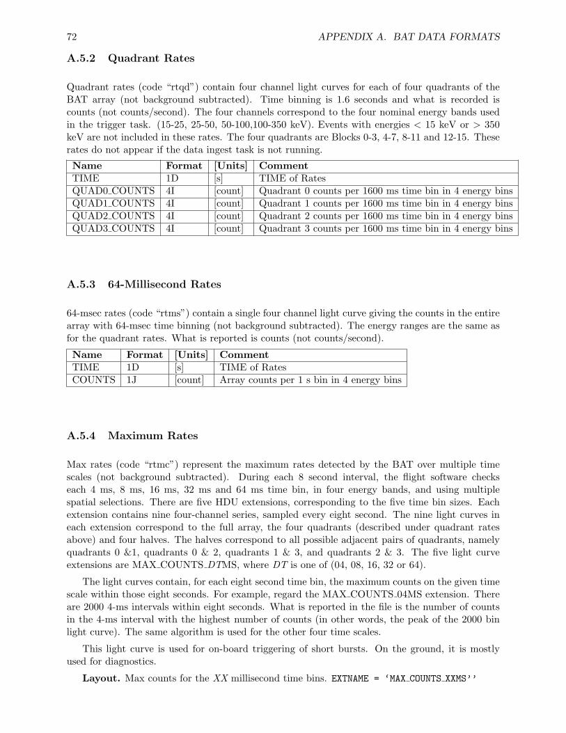
72 APPENDIX A. BAT DATA FORMATS
A.5.2 Quadrant Rates
Quadrant rates (code “rtqd”) contain four channel light curves for each of four quadrants of theBAT array (not background subtracted). Time binning is 1.6 seconds and what is recorded iscounts (not counts/second). The four channels correspond to the four nominal energy bands usedin the trigger task. (15-25, 25-50, 50-100,100-350 keV). Events with energies < 15 keV or > 350keV are not included in these rates. The four quadrants are Blocks 0-3, 4-7, 8-11 and 12-15. Theserates do not appear if the data ingest task is not running.
Name Format [Units] CommentTIME 1D [s] TIME of RatesQUAD0 COUNTS 4I [count] Quadrant 0 counts per 1600 ms time bin in 4 energy binsQUAD1 COUNTS 4I [count] Quadrant 1 counts per 1600 ms time bin in 4 energy binsQUAD2 COUNTS 4I [count] Quadrant 2 counts per 1600 ms time bin in 4 energy binsQUAD3 COUNTS 4I [count] Quadrant 3 counts per 1600 ms time bin in 4 energy bins
A.5.3 64-Millisecond Rates
64-msec rates (code “rtms”) contain a single four channel light curve giving the counts in the entirearray with 64-msec time binning (not background subtracted). The energy ranges are the same asfor the quadrant rates. What is reported is counts (not counts/second).
Name Format [Units] CommentTIME 1D [s] TIME of RatesCOUNTS 1J [count] Array counts per 1 s bin in 4 energy bins
A.5.4 Maximum Rates
Max rates (code “rtmc”) represent the maximum rates detected by the BAT over multiple timescales (not background subtracted). During each 8 second interval, the flight software checkseach 4 ms, 8 ms, 16 ms, 32 ms and 64 ms time bin, in four energy bands, and using multiplespatial selections. There are five HDU extensions, corresponding to the five time bin sizes. Eachextension contains nine four-channel series, sampled every eight second. The nine light curves ineach extension correspond to the full array, the four quadrants (described under quadrant ratesabove) and four halves. The halves correspond to all possible adjacent pairs of quadrants, namelyquadrants 0 &1, quadrants 0 & 2, quadrants 1 & 3, and quadrants 2 & 3. The five light curveextensions are MAX COUNTS DTMS, where DT is one of (04, 08, 16, 32 or 64).
The light curves contain, for each eight second time bin, the maximum counts on the given timescale within those eight seconds. For example, regard the MAX COUNTS 04MS extension. Thereare 2000 4-ms intervals within eight seconds. What is reported in the file is the number of countsin the 4-ms interval with the highest number of counts (in other words, the peak of the 2000 binlight curve). The same algorithm is used for the other four time scales.
This light curve is used for on-board triggering of short bursts. On the ground, it is mostlyused for diagnostics.
Layout. Max counts for the XX millisecond time bins. EXTNAME = ‘MAX COUNTS XXMS’’
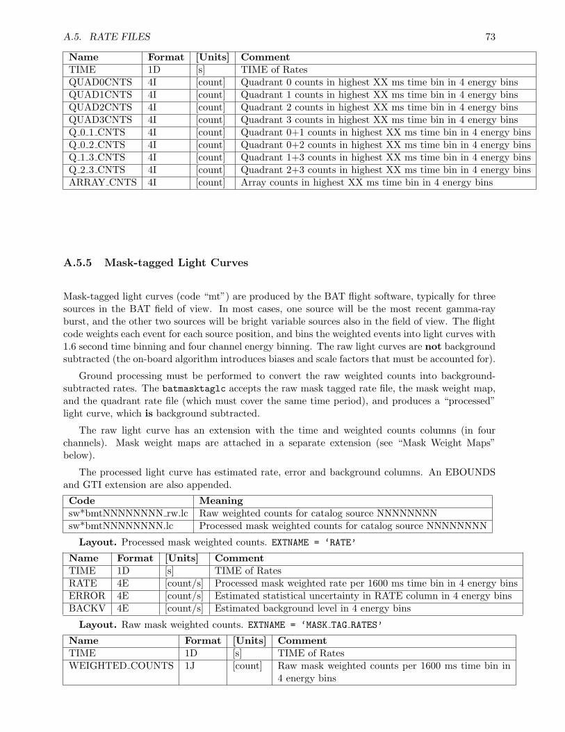
A.5. RATE FILES 73
Name Format [Units] CommentTIME 1D [s] TIME of RatesQUAD0CNTS 4I [count] Quadrant 0 counts in highest XX ms time bin in 4 energy binsQUAD1CNTS 4I [count] Quadrant 1 counts in highest XX ms time bin in 4 energy binsQUAD2CNTS 4I [count] Quadrant 2 counts in highest XX ms time bin in 4 energy binsQUAD3CNTS 4I [count] Quadrant 3 counts in highest XX ms time bin in 4 energy binsQ 0 1 CNTS 4I [count] Quadrant 0+1 counts in highest XX ms time bin in 4 energy binsQ 0 2 CNTS 4I [count] Quadrant 0+2 counts in highest XX ms time bin in 4 energy binsQ 1 3 CNTS 4I [count] Quadrant 1+3 counts in highest XX ms time bin in 4 energy binsQ 2 3 CNTS 4I [count] Quadrant 2+3 counts in highest XX ms time bin in 4 energy binsARRAY CNTS 4I [count] Array counts in highest XX ms time bin in 4 energy bins
A.5.5 Mask-tagged Light Curves
Mask-tagged light curves (code “mt”) are produced by the BAT flight software, typically for threesources in the BAT field of view. In most cases, one source will be the most recent gamma-rayburst, and the other two sources will be bright variable sources also in the field of view. The flightcode weights each event for each source position, and bins the weighted events into light curves with1.6 second time binning and four channel energy binning. The raw light curves are not backgroundsubtracted (the on-board algorithm introduces biases and scale factors that must be accounted for).
Ground processing must be performed to convert the raw weighted counts into background-subtracted rates. The batmasktaglc accepts the raw mask tagged rate file, the mask weight map,and the quadrant rate file (which must cover the same time period), and produces a “processed”light curve, which is background subtracted.
The raw light curve has an extension with the time and weighted counts columns (in fourchannels). Mask weight maps are attached in a separate extension (see “Mask Weight Maps”below).
The processed light curve has estimated rate, error and background columns. An EBOUNDSand GTI extension are also appended.
Code Meaningsw*bmtNNNNNNNN rw.lc Raw weighted counts for catalog source NNNNNNNNsw*bmtNNNNNNNN.lc Processed mask weighted counts for catalog source NNNNNNNN
Layout. Processed mask weighted counts. EXTNAME = ‘RATE’
Name Format [Units] CommentTIME 1D [s] TIME of RatesRATE 4E [count/s] Processed mask weighted rate per 1600 ms time bin in 4 energy binsERROR 4E [count/s] Estimated statistical uncertainty in RATE column in 4 energy binsBACKV 4E [count/s] Estimated background level in 4 energy bins
Layout. Raw mask weighted counts. EXTNAME = ‘MASK TAG RATES’
Name Format [Units] CommentTIME 1D [s] TIME of RatesWEIGHTED COUNTS 1J [count] Raw mask weighted counts per 1600 ms time bin in
4 energy bins
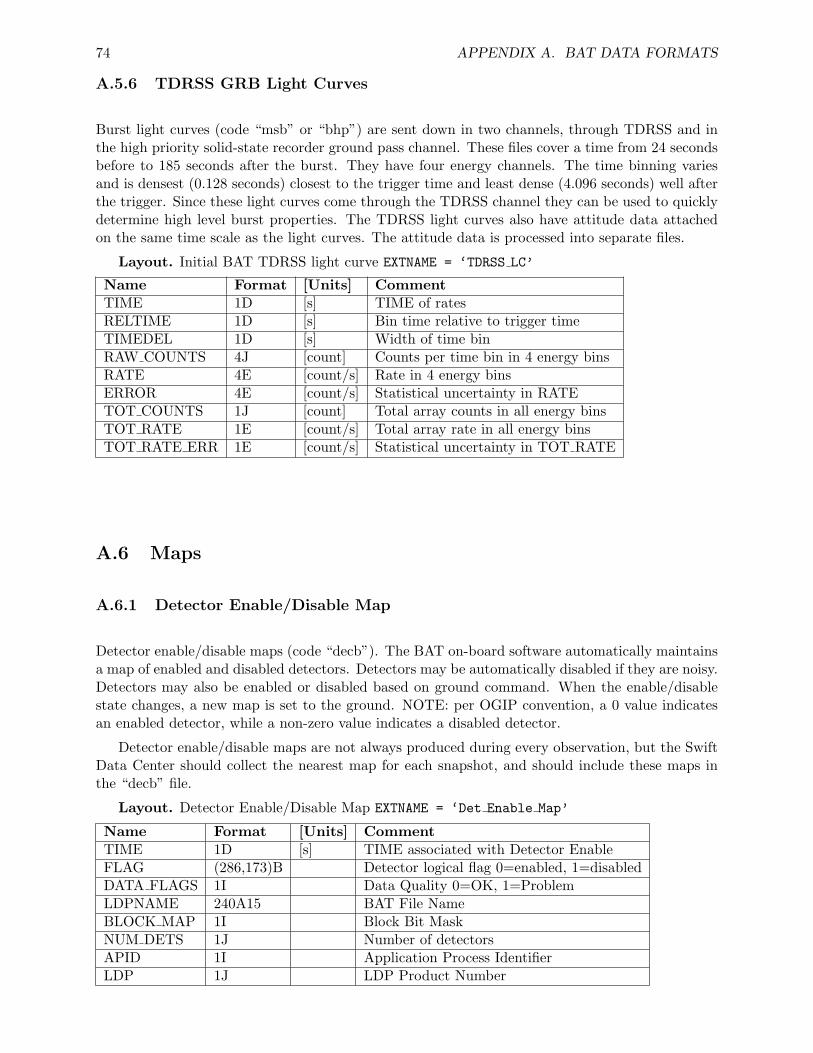
74 APPENDIX A. BAT DATA FORMATS
A.5.6 TDRSS GRB Light Curves
Burst light curves (code “msb” or “bhp”) are sent down in two channels, through TDRSS and inthe high priority solid-state recorder ground pass channel. These files cover a time from 24 secondsbefore to 185 seconds after the burst. They have four energy channels. The time binning variesand is densest (0.128 seconds) closest to the trigger time and least dense (4.096 seconds) well afterthe trigger. Since these light curves come through the TDRSS channel they can be used to quicklydetermine high level burst properties. The TDRSS light curves also have attitude data attachedon the same time scale as the light curves. The attitude data is processed into separate files.
Layout. Initial BAT TDRSS light curve EXTNAME = ‘TDRSS LC’
Name Format [Units] CommentTIME 1D [s] TIME of ratesRELTIME 1D [s] Bin time relative to trigger timeTIMEDEL 1D [s] Width of time binRAW COUNTS 4J [count] Counts per time bin in 4 energy binsRATE 4E [count/s] Rate in 4 energy binsERROR 4E [count/s] Statistical uncertainty in RATETOT COUNTS 1J [count] Total array counts in all energy binsTOT RATE 1E [count/s] Total array rate in all energy binsTOT RATE ERR 1E [count/s] Statistical uncertainty in TOT RATE
A.6 Maps
A.6.1 Detector Enable/Disable Map
Detector enable/disable maps (code “decb”). The BAT on-board software automatically maintainsa map of enabled and disabled detectors. Detectors may be automatically disabled if they are noisy.Detectors may also be enabled or disabled based on ground command. When the enable/disablestate changes, a new map is set to the ground. NOTE: per OGIP convention, a 0 value indicatesan enabled detector, while a non-zero value indicates a disabled detector.
Detector enable/disable maps are not always produced during every observation, but the SwiftData Center should collect the nearest map for each snapshot, and should include these maps inthe “decb” file.
Layout. Detector Enable/Disable Map EXTNAME = ‘Det Enable Map’
Name Format [Units] CommentTIME 1D [s] TIME associated with Detector EnableFLAG (286,173)B Detector logical flag 0=enabled, 1=disabledDATA FLAGS 1I Data Quality 0=OK, 1=ProblemLDPNAME 240A15 BAT File NameBLOCK MAP 1I Block Bit MaskNUM DETS 1J Number of detectorsAPID 1I Application Process IdentifierLDP 1J LDP Product Number
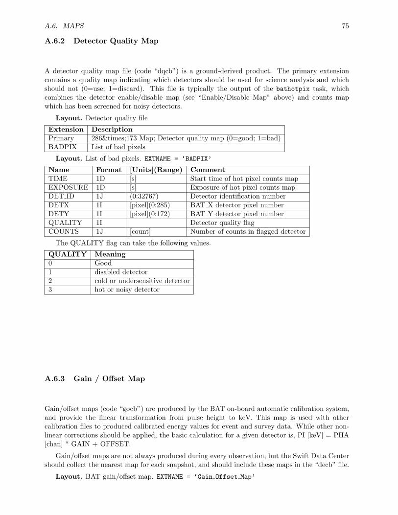
A.6. MAPS 75
A.6.2 Detector Quality Map
A detector quality map file (code “dqcb”) is a ground-derived product. The primary extensioncontains a quality map indicating which detectors should be used for science analysis and whichshould not (0=use; 1=discard). This file is typically the output of the bathotpix task, whichcombines the detector enable/disable map (see “Enable/Disable Map” above) and counts mapwhich has been screened for noisy detectors.
Layout. Detector quality file
Extension DescriptionPrimary 286×173 Map; Detector quality map (0=good; 1=bad)BADPIX List of bad pixels
Layout. List of bad pixels. EXTNAME = ‘BADPIX’
Name Format [Units](Range) CommentTIME 1D [s] Start time of hot pixel counts mapEXPOSURE 1D [s] Exposure of hot pixel counts mapDET ID 1J (0:32767) Detector identification numberDETX 1I [pixel](0:285) BAT X detector pixel numberDETY 1I [pixel](0:172) BAT Y detector pixel numberQUALITY 1I Detector quality flagCOUNTS 1J [count] Number of counts in flagged detector
The QUALITY flag can take the following values.
QUALITY Meaning0 Good1 disabled detector2 cold or undersensitive detector3 hot or noisy detector
A.6.3 Gain / Offset Map
Gain/offset maps (code “gocb”) are produced by the BAT on-board automatic calibration system,and provide the linear transformation from pulse height to keV. This map is used with othercalibration files to produced calibrated energy values for event and survey data. While other non-linear corrections should be applied, the basic calculation for a given detector is, PI [keV] = PHA[chan] * GAIN + OFFSET.
Gain/offset maps are not always produced during every observation, but the Swift Data Centershould collect the nearest map for each snapshot, and should include these maps in the “decb” file.
Layout. BAT gain/offset map. EXTNAME = ‘Gain Offset Map’
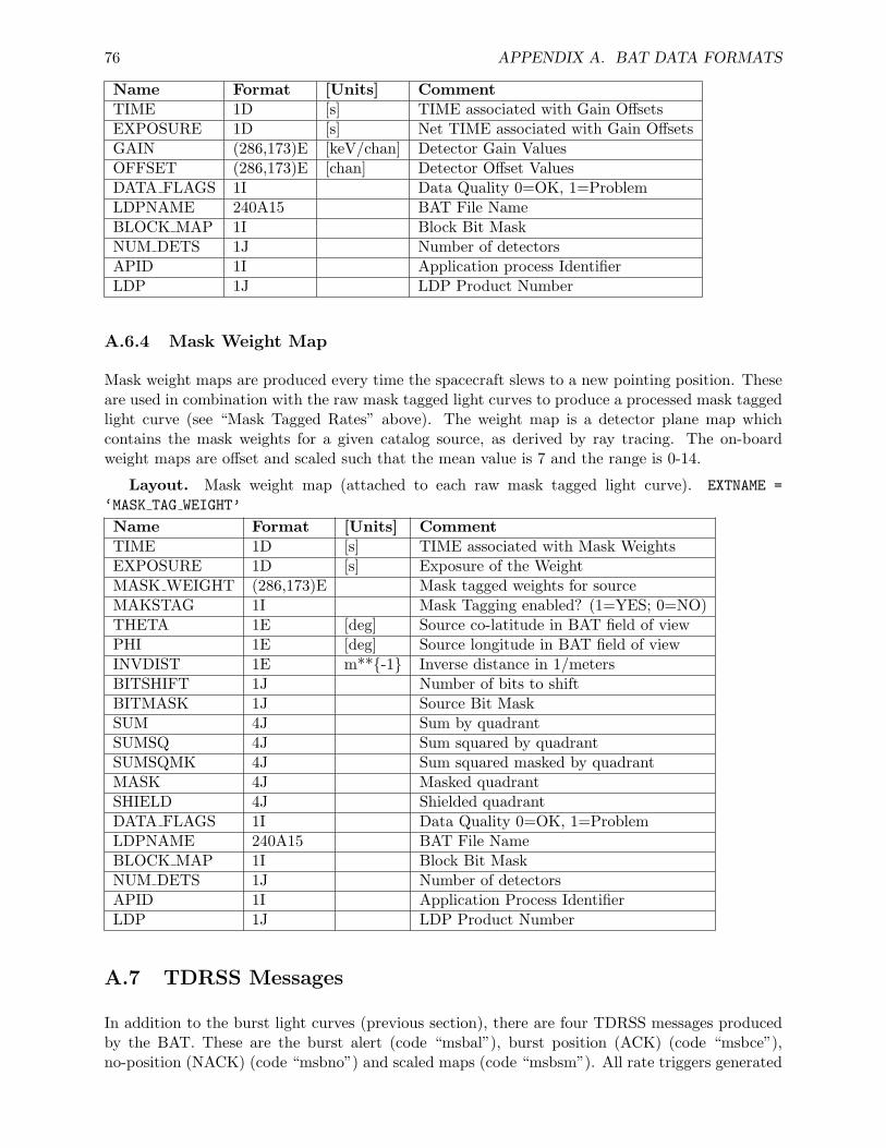
76 APPENDIX A. BAT DATA FORMATS
Name Format [Units] CommentTIME 1D [s] TIME associated with Gain OffsetsEXPOSURE 1D [s] Net TIME associated with Gain OffsetsGAIN (286,173)E [keV/chan] Detector Gain ValuesOFFSET (286,173)E [chan] Detector Offset ValuesDATA FLAGS 1I Data Quality 0=OK, 1=ProblemLDPNAME 240A15 BAT File NameBLOCK MAP 1I Block Bit MaskNUM DETS 1J Number of detectorsAPID 1I Application process IdentifierLDP 1J LDP Product Number
A.6.4 Mask Weight Map
Mask weight maps are produced every time the spacecraft slews to a new pointing position. Theseare used in combination with the raw mask tagged light curves to produce a processed mask taggedlight curve (see “Mask Tagged Rates” above). The weight map is a detector plane map whichcontains the mask weights for a given catalog source, as derived by ray tracing. The on-boardweight maps are offset and scaled such that the mean value is 7 and the range is 0-14.
Layout. Mask weight map (attached to each raw mask tagged light curve). EXTNAME =‘MASK TAG WEIGHT’
Name Format [Units] CommentTIME 1D [s] TIME associated with Mask WeightsEXPOSURE 1D [s] Exposure of the WeightMASK WEIGHT (286,173)E Mask tagged weights for sourceMAKSTAG 1I Mask Tagging enabled? (1=YES; 0=NO)THETA 1E [deg] Source co-latitude in BAT field of viewPHI 1E [deg] Source longitude in BAT field of viewINVDIST 1E m**{-1} Inverse distance in 1/metersBITSHIFT 1J Number of bits to shiftBITMASK 1J Source Bit MaskSUM 4J Sum by quadrantSUMSQ 4J Sum squared by quadrantSUMSQMK 4J Sum squared masked by quadrantMASK 4J Masked quadrantSHIELD 4J Shielded quadrantDATA FLAGS 1I Data Quality 0=OK, 1=ProblemLDPNAME 240A15 BAT File NameBLOCK MAP 1I Block Bit MaskNUM DETS 1J Number of detectorsAPID 1I Application Process IdentifierLDP 1J LDP Product Number
A.7 TDRSS Messages
In addition to the burst light curves (previous section), there are four TDRSS messages producedby the BAT. These are the burst alert (code “msbal”), burst position (ACK) (code “msbce”),no-position (NACK) (code “msbno”) and scaled maps (code “msbsm”). All rate triggers generated
A.7. TDRSS MESSAGES 77
a burst alert. If no position is found, then a burst NACK follows. If a position is found, then aburst position message follows along with a scaled map. In either case (position or no position), ascaled map is sent down in the ground pass.
The burst alert, position and NACK messages are Null Arrays with all information containedin the header.
Scaled maps are detector plane images with a single number for each detector representing thecounts in that detector during the time interval used to produce the image of the burst. Othercolumns contain diagnostic information about the burst.
A.7.1 BAT GRB Alert
This provides the first evidence that the BAT has detected a potential GRB. The BAT monitorsseveral quantities that characterize the gamma-ray sky. Each of these quantities defines an indexinto a table. The BAT triggers when one or more of these quantities exceeds a pre-defined threshold.The BAT GRB Alert message information includes:
• the time when the trigger was detected,
• the table index of the trigger with the highest value, and
• the trigger significance.
A description of possible quantities that can initiate a BAT trigger is contained in Feni-more, et al., ”The Trigger Algorithm for the Burst Alert Telescope on Swift” (astro-ph/0408514;http://content.aip.org/APCPCS/v662/i1/491 1.html).
A.7.2 GRB Position Message (ACK or NACK)
There are two possible BAT position message types: the “BAT ACK” in which a point source canbe imaged and the “BAT NACK” in which no point source is detected in the BAT image. Bothmessage types are distributed through the GCN.
After the GRB Alert Message, the FFT-based image reconstruction from the BAT will confirm(ACK) or not confirm (NACK) that the trigger is from a point source. The ACK message containsthe position of the source, intensity information and the length of the best trigger at the time ofthe alert. This can distinguish between fast and slow bursts but doesn’t give the full-burst fluence.The significance of the detection is included, as well as a flag where each bit gives more detailedinformation on the detection. The BAT position message will have an accuracy of 1–4 arcminutes,depending on the source brightness.
The NACK message is similar in content to the ACK message, but a flag is set to indicate apoint source solution was not found. If the NACK message is received, (a non-confirmed trigger),no other GCN messages follow, except for the diagnostic scaled map from the BAT.
A.7.3 FoM and S/C Will/Will Not Observe
Following an ACK message for the BAT position, the BAT sends the GRB position to the onboardFoM. Two messages follow: FoM will/will not observe and S/C will/will not slew. The first reportswhether the new BAT position had sufficient merit to become the next Automated Target (AT)and to request an autonomous slew. The second gives information about whether the S/C can or
78 APPENDIX A. BAT DATA FORMATS
will slew. In some cases, while the new BAT position may have a high merit, spacecraft pointingconstraints might be such that it is impossible to slew immediately.
A.7.4 BAT Light Curves
The purpose of the BAT TDRSS light curve messages is to provide a quick indication of whatthe burst looks like and to allow it to be classified as long or short. For the lightcurve messages,all counts detected by the entire BAT are telemetered. Note that BAT TDRSS light curvesare not background subtracted. This is made especially complicated during a slew, as otherastrophysical sources enter and leave the BAT field of view. More complete information to do afaithful background-subtraction on BAT light curves is available from the event data.
A set of BAT light curve messages is sent if there is a position for the GRB (i.e., the BATposition message is ACK). All light curves are produced in four (adjustable) energy ranges so thatsome information about the hardness of the GRB may be obtained quickly; the current defaultsare 15–25 keV, 25–50 keV, 50–100 keV, and 100–350 keV.
To insure the very important early-time energy and time evolution information from the GRBis received on the ground, Swift transmits three light curve messages containing overlapping datavia TDRSS, each containing the four band-limited light curves. These are:
First lightcurve message Up to 32 seconds long, spanning T - 24 seconds through T + 8 seconds,where T is the BAT rate trigger time. This message is typically cut off by the slew and mightalso be truncated by the data available when it is produced (i.e. if there are only 5 secondsof data past the trigger at production time, the last three seconds the first light curve willcontain “UNKNOWN” values). Typically sent within 20 seconds of the BAT rate trigger.
Updated first lightcurve message This is a complete 32-second light curve message. To gen-erate it, the BAT software waits about 40 seconds, then continues to wait until Swift is notslewing; it then computes the 32-second light curve spanning the T - 24 seconds through T+ 8 seconds, then transmits the TDRSS message. This is essentially a copy of the first lightcurve message, but it is guaranteed to contain the entire 32 seconds around the GRB triggertime. This message will be useful for identifying bursts that re-brighten within a couple ofminutes after the main trigger.
Second lightcurve message This is 128 seconds long, spanning T - 24 seconds through T + 104seconds. This message is sent within a second of the end of the 128-second light curves, andabout 200 seconds after the BAT rate trigger.
UPDATE (as of Mar 1, 2006) the BAT produces an additional set of light curve information, whichcovers more time, pre- and post-trigger. Also, finer time sampling is available around thetrigger time (to enhance the sensititivity to short bursts). The original light curve is preservedunchanged; the new light curve segments are placed in another extension (EXTNAME =‘TDRSS LC2’).
The final BAT TDRSS message, the scaled map, is for verification of sources foundand/orrefined analysis of sources not found.
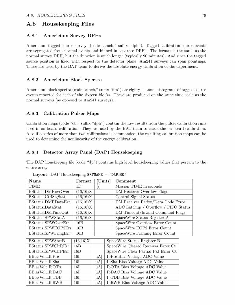
A.8. HOUSEKEEPING FILES 79
A.8 Housekeeping Files
A.8.1 Americium Survey DPHs
Americium tagged source surveys (code “amcb,” suffix “dph”). Tagged calibration source eventsare segregated from normal events and binned in separate DPHs. The format is the same as thenormal survey DPH, but the duration is much longer (typically 90 minutes). And since the taggedsource position is fixed with respect to the detector plane, Am241 surveys can span pointings.These are used by the BAT team to derive the absolute energy calibration of the experiment.
A.8.2 Americium Block Spectra
Americium block spectra (code “amcb,” suffix “fits”) are eighty-channel histograms of tagged sourceevents reported for each of the sixteen blocks. These are produced on the same time scale as thenormal surveys (as opposed to Am241 surveys).
A.8.3 Calibration Pulser Maps
Calibration maps (code “cb,” suffix “dph”) contain the raw results from the pulser calibration runsused in on-board calibration. They are used by the BAT team to check the on-board calibration.Also if a series of more than two calibrations is commanded, the resulting calibration maps can beused to determine the nonlinearity of the energy calibration.
A.8.4 Detector Array Panel (DAP) Housekeeping
The DAP houskeeping file (code “dp”) contains high level housekeeping values that pertain to theentire array.
Layout. DAP Housekeeping EXTNAME = ‘DAP HK’
Name Format [Units] CommentTIME 1D [s] Mission TIME in secondsBStatus DMRcvrOver (16,16)X DM Reciever Overflow FlagsBStatus CtrlSigStat (16,16)X Control Signal StatusBStatus DMRDataErr (16,16)X DM Receiver Parity/Data Code ErrorBStatus DataStat (16,16)X ADC Latchup / Overflow / FIFO StatusBStatus DMTimeOut (16,16)X DM Timeout/Invalid Command FlagsBStatus SPWStatA (16,16)X SpaceWire Status Register ABStatus SPWOverErr 16B SpaceWire Overflow Error CountBStatus SPWEOP2Err 16B SpaceWire EOP2 Error CountBStatus SPWFrmgErr 16B SpaceWire Framing Error Count
BStatus SPWStatB (16,16)X SpaceWire Status Register BBStatus SPWClrRErr 16B SpaceWire Cleared Receiver Error CtBStatus SPWClrPErr 16B SpaceWire Clear Partial Pkt Error CtBBiasVolt IbPre 16I [uA] IbPre Bias Voltage ADC ValueBBiasVolt IbSha 16I [uA] IbSha Bias Voltage ADC ValueBBiasVolt IbOTA 16I [uA] IbOTA Bias Voltage ADC ValueBBiasVolt IbDAC 16I [uA] IbDAC Bias Voltage ADC ValueBBiasVolt IbTDB 16I [uA] IbTDB Bias Voltage ADC ValueBBiasVolt IbRWB 16I [uA] IbRWB Bias Voltage ADC Value
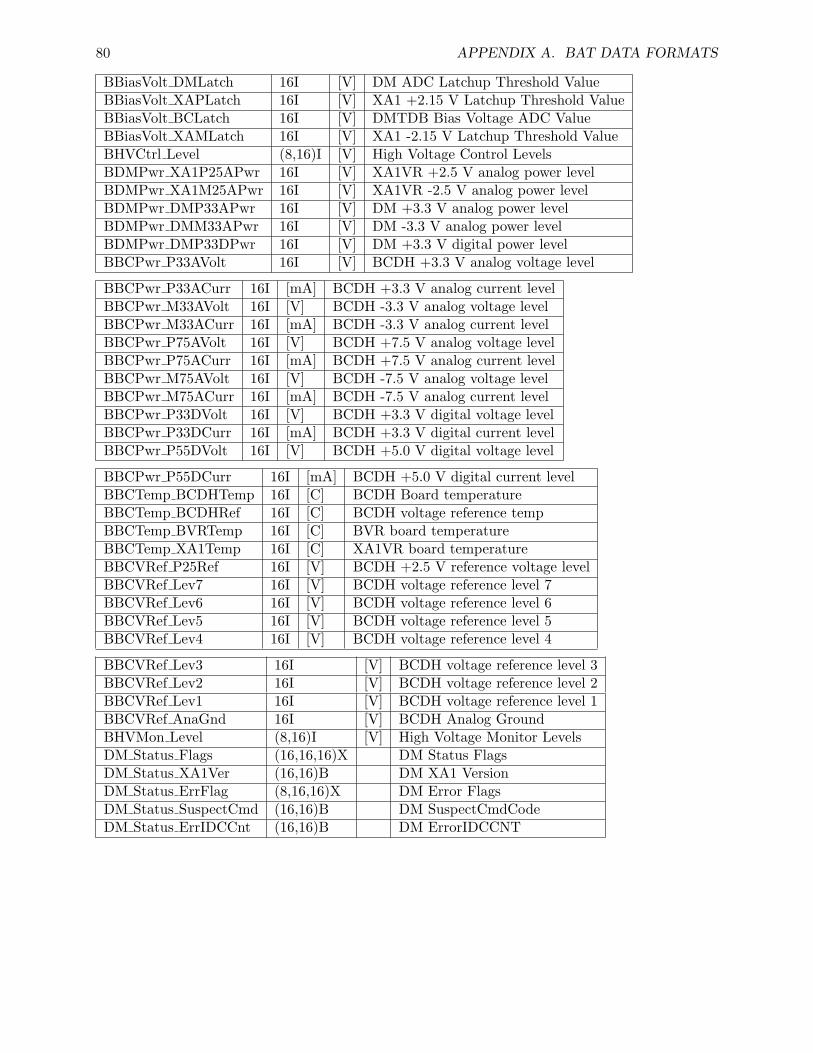
80 APPENDIX A. BAT DATA FORMATS
BBiasVolt DMLatch 16I [V] DM ADC Latchup Threshold ValueBBiasVolt XAPLatch 16I [V] XA1 +2.15 V Latchup Threshold ValueBBiasVolt BCLatch 16I [V] DMTDB Bias Voltage ADC ValueBBiasVolt XAMLatch 16I [V] XA1 -2.15 V Latchup Threshold ValueBHVCtrl Level (8,16)I [V] High Voltage Control LevelsBDMPwr XA1P25APwr 16I [V] XA1VR +2.5 V analog power levelBDMPwr XA1M25APwr 16I [V] XA1VR -2.5 V analog power levelBDMPwr DMP33APwr 16I [V] DM +3.3 V analog power levelBDMPwr DMM33APwr 16I [V] DM -3.3 V analog power levelBDMPwr DMP33DPwr 16I [V] DM +3.3 V digital power levelBBCPwr P33AVolt 16I [V] BCDH +3.3 V analog voltage level
BBCPwr P33ACurr 16I [mA] BCDH +3.3 V analog current levelBBCPwr M33AVolt 16I [V] BCDH -3.3 V analog voltage levelBBCPwr M33ACurr 16I [mA] BCDH -3.3 V analog current levelBBCPwr P75AVolt 16I [V] BCDH +7.5 V analog voltage levelBBCPwr P75ACurr 16I [mA] BCDH +7.5 V analog current levelBBCPwr M75AVolt 16I [V] BCDH -7.5 V analog voltage levelBBCPwr M75ACurr 16I [mA] BCDH -7.5 V analog current levelBBCPwr P33DVolt 16I [V] BCDH +3.3 V digital voltage levelBBCPwr P33DCurr 16I [mA] BCDH +3.3 V digital current levelBBCPwr P55DVolt 16I [V] BCDH +5.0 V digital voltage level
BBCPwr P55DCurr 16I [mA] BCDH +5.0 V digital current levelBBCTemp BCDHTemp 16I [C] BCDH Board temperatureBBCTemp BCDHRef 16I [C] BCDH voltage reference tempBBCTemp BVRTemp 16I [C] BVR board temperatureBBCTemp XA1Temp 16I [C] XA1VR board temperatureBBCVRef P25Ref 16I [V] BCDH +2.5 V reference voltage levelBBCVRef Lev7 16I [V] BCDH voltage reference level 7BBCVRef Lev6 16I [V] BCDH voltage reference level 6BBCVRef Lev5 16I [V] BCDH voltage reference level 5BBCVRef Lev4 16I [V] BCDH voltage reference level 4
BBCVRef Lev3 16I [V] BCDH voltage reference level 3BBCVRef Lev2 16I [V] BCDH voltage reference level 2BBCVRef Lev1 16I [V] BCDH voltage reference level 1BBCVRef AnaGnd 16I [V] BCDH Analog GroundBHVMon Level (8,16)I [V] High Voltage Monitor LevelsDM Status Flags (16,16,16)X DM Status FlagsDM Status XA1Ver (16,16)B DM XA1 VersionDM Status ErrFlag (8,16,16)X DM Error FlagsDM Status SuspectCmd (16,16)B DM SuspectCmdCodeDM Status ErrIDCCnt (16,16)B DM ErrorIDCCNT
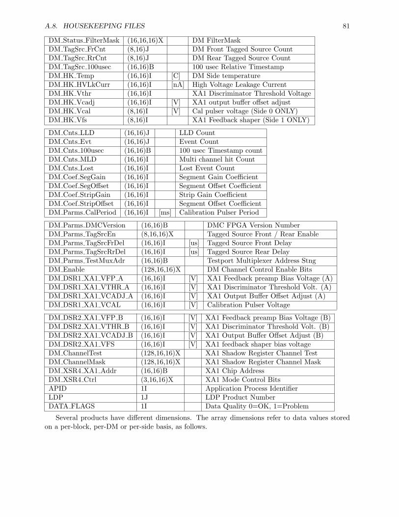
A.8. HOUSEKEEPING FILES 81
DM Status FilterMask (16,16,16)X DM FilterMaskDM TagSrc FrCnt (8,16)J DM Front Tagged Source CountDM TagSrc RrCnt (8,16)J DM Rear Tagged Source CountDM TagSrc 100usec (16,16)B 100 usec Relative TimestampDM HK Temp (16,16)I [C] DM Side temperatureDM HK HVLkCurr (16,16)I [nA] High Voltage Leakage CurrentDM HK Vthr (16,16)I XA1 Discriminator Threshold VoltageDM HK Vcadj (16,16)I [V] XA1 output buffer offset adjustDM HK Vcal (8,16)I [V] Cal pulser voltage (Side 0 ONLY)DM HK Vfs (8,16)I XA1 Feedback shaper (Side 1 ONLY)
DM Cnts LLD (16,16)J LLD CountDM Cnts Evt (16,16)J Event CountDM Cnts 100usec (16,16)B 100 usec Timestamp countDM Cnts MLD (16,16)I Multi channel hit CountDM Cnts Lost (16,16)I Lost Event CountDM Coef SegGain (16,16)I Segment Gain CoefficientDM Coef SegOffset (16,16)I Segment Offset CoefficientDM Coef StripGain (16,16)I Strip Gain CoefficientDM Coef StripOffset (16,16)I Segment Offset CoefficientDM Parms CalPeriod (16,16)I [ms] Calibration Pulser Period
DM Parms DMCVersion (16,16)B DMC FPGA Version NumberDM Parms TagSrcEn (8,16,16)X Tagged Source Front / Rear EnableDM Parms TagSrcFrDel (16,16)I [us] Tagged Source Front DelayDM Parms TagSrcRrDel (16,16)I [us] Tagged Source Rear DelayDM Parms TestMuxAdr (16,16)B Testport Multiplexer Address StngDM Enable (128,16,16)X DM Channel Control Enable BitsDM DSR1 XA1 VFP A (16,16)I [V] XA1 Feedback preamp Bias Voltage (A)DM DSR1 XA1 VTHR A (16,16)I [V] XA1 Discriminator Threshold Volt. (A)DM DSR1 XA1 VCADJ A (16,16)I [V] XA1 Output Buffer Offset Adjust (A)DM DSR1 XA1 VCAL (16,16)I [V] Calibration Pulser Voltage
DM DSR2 XA1 VFP B (16,16)I [V] XA1 Feedback preamp Bias Voltage (B)DM DSR2 XA1 VTHR B (16,16)I [V] XA1 Discriminator Threshold Volt. (B)DM DSR2 XA1 VCADJ B (16,16)I [V] XA1 Output Buffer Offset Adjust (B)DM DSR2 XA1 VFS (16,16)I [V] XA1 feedback shaper bias voltageDM ChannelTest (128,16,16)X XA1 Shadow Register Channel TestDM ChannelMask (128,16,16)X XA1 Shadow Register Channel MaskDM XSR4 XA1 Addr (16,16)B XA1 Chip AddressDM XSR4 Ctrl (3,16,16)X XA1 Mode Control BitsAPID 1I Application Process IdentifierLDP 1J LDP Product NumberDATA FLAGS 1I Data Quality 0=OK, 1=Problem
Several products have different dimensions. The array dimensions refer to data values storedon a per-block, per-DM or per-side basis, as follows.
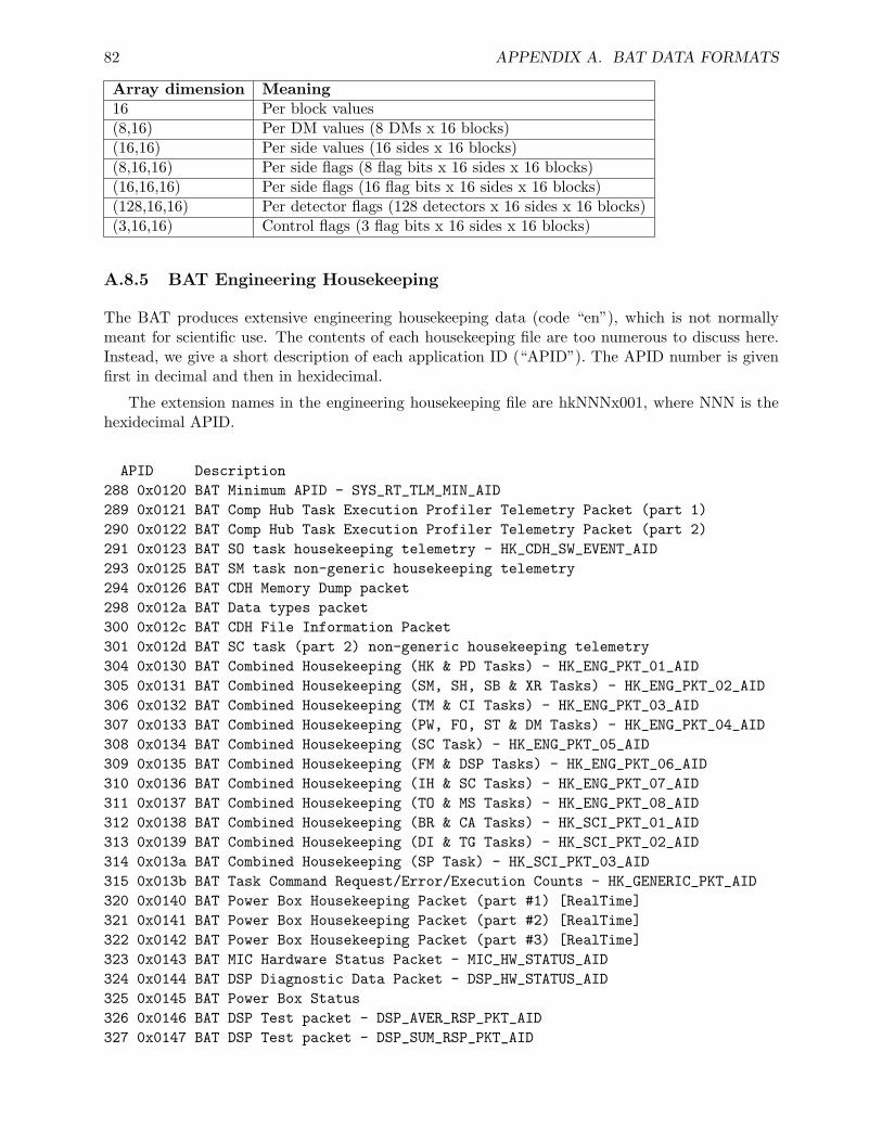
82 APPENDIX A. BAT DATA FORMATS
Array dimension Meaning16 Per block values(8,16) Per DM values (8 DMs x 16 blocks)(16,16) Per side values (16 sides x 16 blocks)(8,16,16) Per side flags (8 flag bits x 16 sides x 16 blocks)(16,16,16) Per side flags (16 flag bits x 16 sides x 16 blocks)(128,16,16) Per detector flags (128 detectors x 16 sides x 16 blocks)(3,16,16) Control flags (3 flag bits x 16 sides x 16 blocks)
A.8.5 BAT Engineering Housekeeping
The BAT produces extensive engineering housekeeping data (code “en”), which is not normallymeant for scientific use. The contents of each housekeeping file are too numerous to discuss here.Instead, we give a short description of each application ID (“APID”). The APID number is givenfirst in decimal and then in hexidecimal.
The extension names in the engineering housekeeping file are hkNNNx001, where NNN is thehexidecimal APID.
APID Description288 0x0120 BAT Minimum APID - SYS_RT_TLM_MIN_AID289 0x0121 BAT Comp Hub Task Execution Profiler Telemetry Packet (part 1)290 0x0122 BAT Comp Hub Task Execution Profiler Telemetry Packet (part 2)291 0x0123 BAT SO task housekeeping telemetry - HK_CDH_SW_EVENT_AID293 0x0125 BAT SM task non-generic housekeeping telemetry294 0x0126 BAT CDH Memory Dump packet298 0x012a BAT Data types packet300 0x012c BAT CDH File Information Packet301 0x012d BAT SC task (part 2) non-generic housekeeping telemetry304 0x0130 BAT Combined Housekeeping (HK & PD Tasks) - HK_ENG_PKT_01_AID305 0x0131 BAT Combined Housekeeping (SM, SH, SB & XR Tasks) - HK_ENG_PKT_02_AID306 0x0132 BAT Combined Housekeeping (TM & CI Tasks) - HK_ENG_PKT_03_AID307 0x0133 BAT Combined Housekeeping (PW, FO, ST & DM Tasks) - HK_ENG_PKT_04_AID308 0x0134 BAT Combined Housekeeping (SC Task) - HK_ENG_PKT_05_AID309 0x0135 BAT Combined Housekeeping (FM & DSP Tasks) - HK_ENG_PKT_06_AID310 0x0136 BAT Combined Housekeeping (IH & SC Tasks) - HK_ENG_PKT_07_AID311 0x0137 BAT Combined Housekeeping (TO & MS Tasks) - HK_ENG_PKT_08_AID312 0x0138 BAT Combined Housekeeping (BR & CA Tasks) - HK_SCI_PKT_01_AID313 0x0139 BAT Combined Housekeeping (DI & TG Tasks) - HK_SCI_PKT_02_AID314 0x013a BAT Combined Housekeeping (SP Task) - HK_SCI_PKT_03_AID315 0x013b BAT Task Command Request/Error/Execution Counts - HK_GENERIC_PKT_AID320 0x0140 BAT Power Box Housekeeping Packet (part #1) [RealTime]321 0x0141 BAT Power Box Housekeeping Packet (part #2) [RealTime]322 0x0142 BAT Power Box Housekeeping Packet (part #3) [RealTime]323 0x0143 BAT MIC Hardware Status Packet - MIC_HW_STATUS_AID324 0x0144 BAT DSP Diagnostic Data Packet - DSP_HW_STATUS_AID325 0x0145 BAT Power Box Status326 0x0146 BAT DSP Test packet - DSP_AVER_RSP_PKT_AID327 0x0147 BAT DSP Test packet - DSP_SUM_RSP_PKT_AID
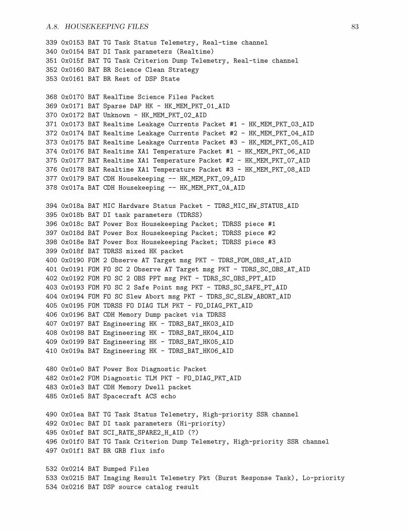
A.8. HOUSEKEEPING FILES 83
339 0x0153 BAT TG Task Status Telemetry, Real-time channel340 0x0154 BAT DI Task parameters (Realtime)351 0x015f BAT TG Task Criterion Dump Telemetry, Real-time channel352 0x0160 BAT BR Science Clean Strategy353 0x0161 BAT BR Rest of DSP State
368 0x0170 BAT RealTime Science Files Packet369 0x0171 BAT Sparse DAP HK - HK_MEM_PKT_01_AID370 0x0172 BAT Unknown - HK_MEM_PKT_02_AID371 0x0173 BAT Realtime Leakage Currents Packet #1 - HK_MEM_PKT_03_AID372 0x0174 BAT Realtime Leakage Currents Packet #2 - HK_MEM_PKT_04_AID373 0x0175 BAT Realtime Leakage Currents Packet #3 - HK_MEM_PKT_05_AID374 0x0176 BAT Realtime XA1 Temperature Packet #1 - HK_MEM_PKT_06_AID375 0x0177 BAT Realtime XA1 Temperature Packet #2 - HK_MEM_PKT_07_AID376 0x0178 BAT Realtime XA1 Temperature Packet #3 - HK_MEM_PKT_08_AID377 0x0179 BAT CDH Housekeeping -- HK_MEM_PKT_09_AID378 0x017a BAT CDH Housekeeping -- HK_MEM_PKT_0A_AID
394 0x018a BAT MIC Hardware Status Packet - TDRS_MIC_HW_STATUS_AID395 0x018b BAT DI task parameters (TDRSS)396 0x018c BAT Power Box Housekeeping Packet; TDRSS piece #1397 0x018d BAT Power Box Housekeeping Packet; TDRSS piece #2398 0x018e BAT Power Box Housekeeping Packet; TDRSS piece #3399 0x018f BAT TDRSS mixed HK packet400 0x0190 FOM 2 Observe AT Target msg PKT - TDRS_FOM_OBS_AT_AID401 0x0191 FOM FO SC 2 Observe AT Target msg PKT - TDRS_SC_OBS_AT_AID402 0x0192 FOM FO SC 2 OBS PPT msg PKT - TDRS_SC_OBS_PPT_AID403 0x0193 FOM FO SC 2 Safe Point msg PKT - TDRS_SC_SAFE_PT_AID404 0x0194 FOM FO SC Slew Abort msg PKT - TDRS_SC_SLEW_ABORT_AID405 0x0195 FOM TDRSS FO DIAG TLM PKT - FO_DIAG_PKT_AID406 0x0196 BAT CDH Memory Dump packet via TDRSS407 0x0197 BAT Engineering HK - TDRS_BAT_HK03_AID408 0x0198 BAT Engineering HK - TDRS_BAT_HK04_AID409 0x0199 BAT Engineering HK - TDRS_BAT_HK05_AID410 0x019a BAT Engineering HK - TDRS_BAT_HK06_AID
480 0x01e0 BAT Power Box Diagnostic Packet482 0x01e2 FOM Diagnostic TLM PKT - FO_DIAG_PKT_AID483 0x01e3 BAT CDH Memory Dwell packet485 0x01e5 BAT Spacecraft ACS echo
490 0x01ea BAT TG Task Status Telemetry, High-priority SSR channel492 0x01ec BAT DI task parameters (Hi-priority)495 0x01ef BAT SCI_RATE_SPARE2_H_AID (?)496 0x01f0 BAT TG Task Criterion Dump Telemetry, High-priority SSR channel497 0x01f1 BAT BR GRB flux info
532 0x0214 BAT Bumped Files533 0x0215 BAT Imaging Result Telemetry Pkt (Burst Response Task), Lo-priority534 0x0216 BAT DSP source catalog result
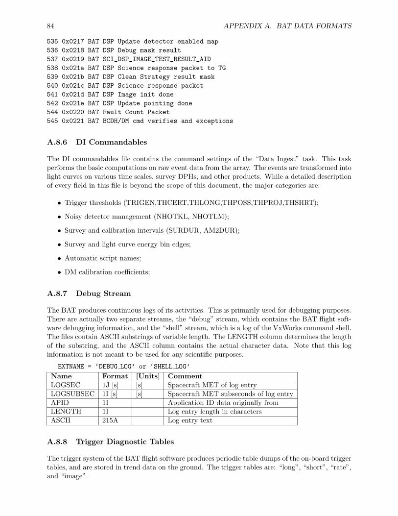
84 APPENDIX A. BAT DATA FORMATS
535 0x0217 BAT DSP Update detector enabled map536 0x0218 BAT DSP Debug mask result537 0x0219 BAT SCI_DSP_IMAGE_TEST_RESULT_AID538 0x021a BAT DSP Science response packet to TG539 0x021b BAT DSP Clean Strategy result mask540 0x021c BAT DSP Science response packet541 0x021d BAT DSP Image init done542 0x021e BAT DSP Update pointing done544 0x0220 BAT Fault Count Packet545 0x0221 BAT BCDH/DM cmd verifies and exceptions
A.8.6 DI Commandables
The DI commandables file contains the command settings of the “Data Ingest” task. This taskperforms the basic computations on raw event data from the array. The events are transformed intolight curves on various time scales, survey DPHs, and other products. While a detailed descriptionof every field in this file is beyond the scope of this document, the major categories are:
• Trigger thresholds (TRIGEN,THCERT,THLONG,THPOSS,THPROJ,THSHRT);
• Noisy detector management (NHOTKL, NHOTLM);
• Survey and calibration intervals (SURDUR, AM2DUR);
• Survey and light curve energy bin edges;
• Automatic script names;
• DM calibration coefficients;
A.8.7 Debug Stream
The BAT produces continuous logs of its activities. This is primarily used for debugging purposes.There are actually two separate streams, the “debug” stream, which contains the BAT flight soft-ware debugging information, and the “shell” stream, which is a log of the VxWorks command shell.The files contain ASCII substrings of variable length. The LENGTH column determines the lengthof the substring, and the ASCII column contains the actual character data. Note that this loginformation is not meant to be used for any scientific purposes.
EXTNAME = ‘DEBUG LOG’ or ‘SHELL LOG’
Name Format [Units] CommentLOGSEC 1J [s] [s] Spacecraft MET of log entryLOGSUBSEC 1I [s] [s] Spacecraft MET subseconds of log entryAPID 1I Application ID data originally fromLENGTH 1I Log entry length in charactersASCII 215A Log entry text
A.8.8 Trigger Diagnostic Tables
The trigger system of the BAT flight software produces periodic table dumps of the on-board triggertables, and are stored in trend data on the ground. The trigger tables are: “long”, “short”, “rate”,and “image”.

Appendix B
BAT FITS Keywords
B.1 Introduction
The BAT ground software operates on standard FITS data files. However, the software produces— and requires — certain FITS keywords in order to operate properly. This appendix describesthe keywords used. It also describes the HDUCLASn keywords used to identify the contents ofdata files.
B.1.1 Keywords Used
The BAT software uses FITS keywords to both document the analysis procedures used, and topass information to downstream tasks. This section lists those keywords, how they are created andused, and by what tasks.
• ACOLAPP - a boolean keyword indicating whether the autocollimation correction has beenapplied to the image plate scale. Set by: batfftimage. Used by: none.
• BACKAPP - a boolean keyword which indicates whether the BAT background has beensubtracted. This can mean some form of explicit subtraction, or automatic subtraction viathe mask-weighting/imaging approaches. Set by: batfftimage,batbinevt. Used by: batclean.
• BALAPP - a boolean keyword indicating whether fine-level balancing has been performedon a detector image. Set by: batclean. Used by: NONE
• BAT {X,Y,Z}OBJ - floating point keywords which indicate where in the BAT field ofview the source is located. The coordinate system is the BAT coordinate system, and theunits are centimeters. Objects at at infinity are placed at 10 km. Set by: batmaskwtevt,batmaskwtimg, batupdatephakw. Used by: batcelldetect, batdrmgen.
• BAT RA, BAT DEC - floating point keywords which indicate where on the sky the sourceis located (celestial RA and Dec). Set by: batmaskwtevt, batmaskwtimg. Used by: NONE.
• CLEANLEV - an integer keyword indicating the number of iterations of cleaning have beenperformed. Set by: batclean. Used by: batclean.
• DISTAPP - a boolean keyword indicating whether the image, mask weights, or source detec-tion results have been adjusted for non-linear image distortion effects. Set by: batcelldetect,batwarpimg, batmaskwtevt, batmaskwtimg. Used by: batwarpimg, batcelldetect.
85
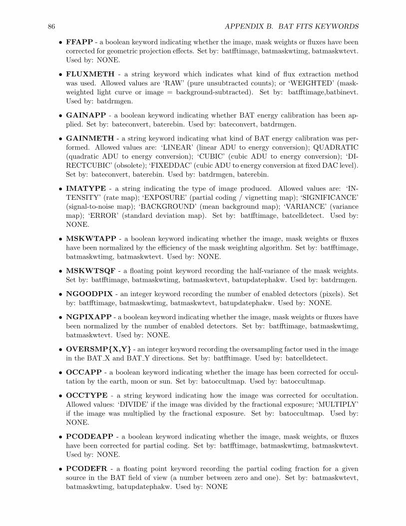
86 APPENDIX B. BAT FITS KEYWORDS
• FFAPP - a boolean keyword indicating whether the image, mask weights or fluxes have beencorrected for geometric projection effects. Set by: batfftimage, batmaskwtimg, batmaskwtevt.Used by: NONE.
• FLUXMETH - a string keyword which indicates what kind of flux extraction methodwas used. Allowed values are ‘RAW’ (pure unsubtracted counts); or ‘WEIGHTED’ (mask-weighted light curve or image = background-subtracted). Set by: batfftimage,batbinevt.Used by: batdrmgen.
• GAINAPP - a boolean keyword indicating whether BAT energy calibration has been ap-plied. Set by: bateconvert, baterebin. Used by: bateconvert, batdrmgen.
• GAINMETH - a string keyword indicating what kind of BAT energy calibration was per-formed. Allowed values are: ‘LINEAR’ (linear ADU to energy conversion); QUADRATIC(quadratic ADU to energy conversion); ‘CUBIC’ (cubic ADU to energy conversion); ‘DI-RECTCUBIC’ (obsolete); ‘FIXEDDAC’ (cubic ADU to energy conversion at fixed DAC level).Set by: bateconvert, baterebin. Used by: batdrmgen, baterebin.
• IMATYPE - a string indicating the type of image produced. Allowed values are: ‘IN-TENSITY’ (rate map); ‘EXPOSURE’ (partial coding / vignetting map); ‘SIGNIFICANCE’(signal-to-noise map); ‘BACKGROUND’ (mean background map); ‘VARIANCE’ (variancemap); ‘ERROR’ (standard deviation map). Set by: batfftimage, batcelldetect. Used by:NONE.
• MSKWTAPP - a boolean keyword indicating whether the image, mask weights or fluxeshave been normalized by the efficiency of the mask weighting algorithm. Set by: batfftimage,batmaskwtimg, batmaskwtevt. Used by: NONE.
• MSKWTSQF - a floating point keyword recording the half-variance of the mask weights.Set by: batfftimage, batmaskwtimg, batmaskwtevt, batupdatephakw. Used by: batdrmgen.
• NGOODPIX - an integer keyword recording the number of enabled detectors (pixels). Setby: batfftimage, batmaskwtimg, batmaskwtevt, batupdatephakw. Used by: NONE.
• NGPIXAPP - a boolean keyword indicating whether the image, mask weights or fluxes havebeen normalized by the number of enabled detectors. Set by: batfftimage, batmaskwtimg,batmaskwtevt. Used by: NONE.
• OVERSMP{X,Y} - an integer keyword recording the oversampling factor used in the imagein the BAT X and BAT Y directions. Set by: batfftimage. Used by: batcelldetect.
• OCCAPP - a boolean keyword indicating whether the image has been corrected for occul-tation by the earth, moon or sun. Set by: batoccultmap. Used by: batoccultmap.
• OCCTYPE - a string keyword indicating how the image was corrected for occultation.Allowed values: ‘DIVIDE’ if the image was divided by the fractional exposure; ‘MULTIPLY’if the image was multiplied by the fractional exposure. Set by: batoccultmap. Used by:NONE.
• PCODEAPP - a boolean keyword indicating whether the image, mask weights, or fluxeshave been corrected for partial coding. Set by: batfftimage, batmaskwtimg, batmaskwtevt.Used by: NONE.
• PCODEFR - a floating point keyword recording the partial coding fraction for a givensource in the BAT field of view (a number between zero and one). Set by: batmaskwtevt,batmaskwtimg, batupdatephakw. Used by: NONE
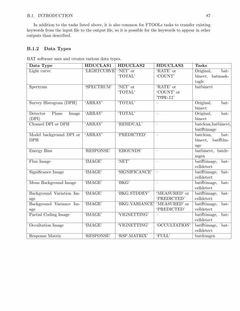
B.1. INTRODUCTION 87
In addition to the tasks listed above, it is also common for FTOOLs tasks to transfer existingkeywords from the input file to the output file, so it is possible for the keywords to appear in otheroutputs than described.
B.1.2 Data Types
BAT software uses and creates various data types.
Data Type HDUCLAS1 HDUCLAS2 HDUCLAS3 TasksLight curve ‘LIGHTCURVE’ ‘NET’ or
‘TOTAL’‘RATE’ or‘COUNT’
Original, bat-binevt, batmask-taglc
Spectrum ‘SPECTRUM’ ‘NET’ or‘TOTAL’
‘RATE’ or‘COUNT’ or’TYPE:II’
batbinevt
Survey Histogram (DPH) ‘ARRAY’ ‘TOTAL’ – Original, bat-binevt
Detector Plane Image(DPI)
‘ARRAY’ ‘TOTAL’ – Original, bat-binevt
Cleaned DPI or DPH ‘ARRAY’ ‘RESIDUAL’ – batclean,batbinevt,batfftimage
Model background DPI orDPH
‘ARRAY’ ‘PREDICTED’ – batclean, bat-binevt, batfftim-age
Energy Bins ‘RESPONSE’ ‘EBOUNDS’ – batbinevt, batdr-mgen
Flux Image ‘IMAGE’ ‘NET’ – batfftimage, bat-celldetect
Significance Image ‘IMAGE’ ‘SIGNIFICANCE’ – batfftimage, bat-celldetect
Mean Background Image ‘IMAGE’ ‘BKG’ – batfftimage, bat-celldetect
Background Variation Im-age
‘IMAGE’ ‘BKG STDDEV’ ‘MEASURED’ or‘PREDICTED’
batfftimage, bat-celldetect
Background Variance Im-age
‘IMAGE’ ‘BKG VARIANCE’ ‘MEASURED’ or‘PREDICTED’
batfftimage, bat-celldetect
Partial Coding Image ‘IMAGE’ ‘VIGNETTING’ – batfftimage, bat-celldetect
Occultation Image ‘IMAGE’ ‘VIGNETTING’ ‘OCCULTATION’ batfftimage, bat-celldetect
Response Matrix ‘RESPONSE’ ‘RSP MATRIX’ ‘FULL’ batdrmgen

88 APPENDIX B. BAT FITS KEYWORDS

Appendix C
BAT Acronym and TerminologyGlossary
This Appendix contains a glossary of special terms and acronyms related to the BAT.
1553 Bus Communication bus connecting the BAT to the spacecraft systems.
Aperture pattern of open and blocked cells used in the BAT mask. Also, the aperture data filerecords this pattern for use in image analysis.
BAT Burst Alert Telescope
Block A BAT block contains 8 DMs and 2048 detectors. There are 16 blocks in the detector array.
CALDB Calibration Database, used to store calibration and auxiliary files for science analysis.Available from the Swift web page.
CdZnTe Cadmium Zinc Teluride, the BAT detector technology.
CZT same as CdZnTe.
Coded Aperture A type of non-imaging optics, consisting of absorbing elements arranged in aspecific pattern above a detector plane.
DAP Detector Array Plane, a term which refers to the entire detector array.
Disable/Enable Map Map produced on-board which contains the individual detectors whichwere enabled or disabled. A disable/enable map is produced whenever the instrument con-figuration changes on board, and should be present in each observation data set.
DM Detector Module, a component that contains two DM Sides and 256 detectors.
DM Side Detector Module Side, containing 128 detectors. Two sides are arranged into a singleDetector Module.
DPH Detector Plane Histogram, a histogram accumulated for each detector in several energybands.
DPI Detector Plane Image, an image (histogram) accumulated for each detector in a single energyband.
DRM Detector Response Matrix, the response function used in spectral analysis.
89
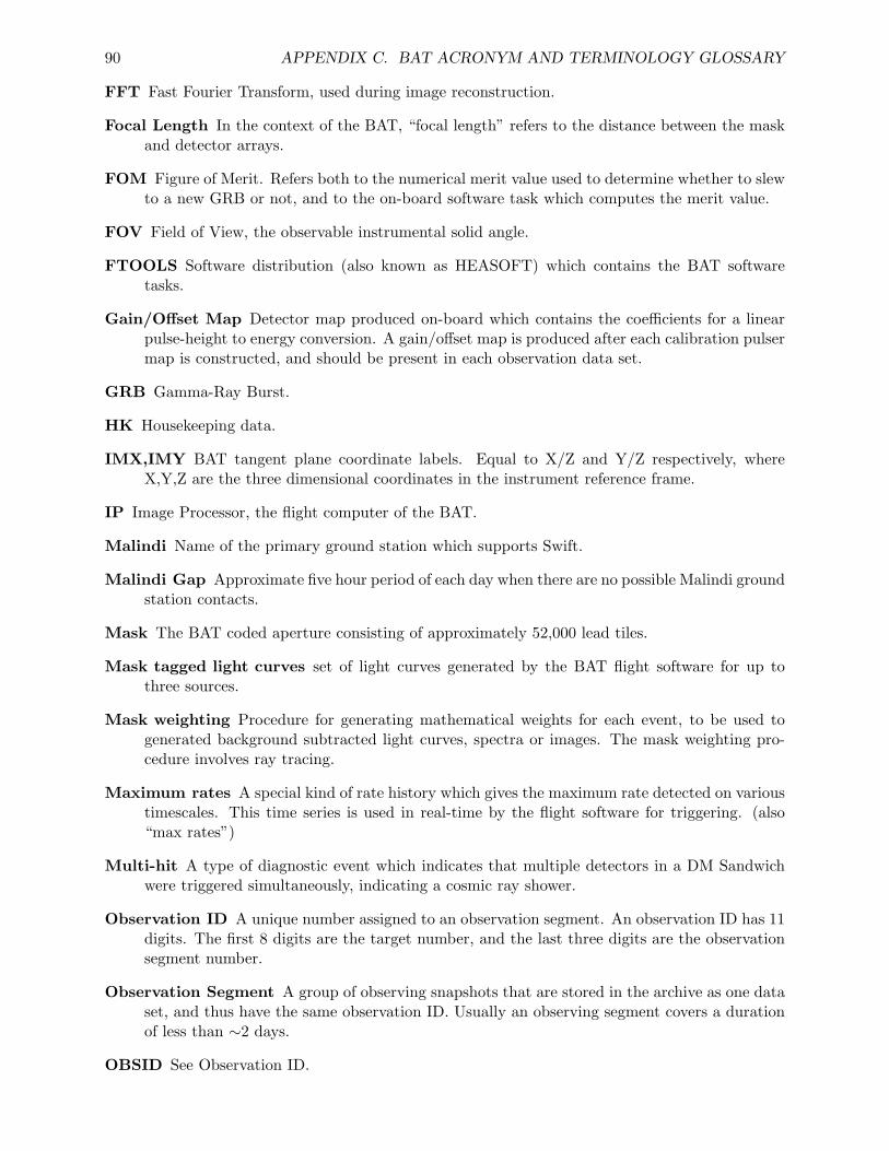
90 APPENDIX C. BAT ACRONYM AND TERMINOLOGY GLOSSARY
FFT Fast Fourier Transform, used during image reconstruction.
Focal Length In the context of the BAT, “focal length” refers to the distance between the maskand detector arrays.
FOM Figure of Merit. Refers both to the numerical merit value used to determine whether to slewto a new GRB or not, and to the on-board software task which computes the merit value.
FOV Field of View, the observable instrumental solid angle.
FTOOLS Software distribution (also known as HEASOFT) which contains the BAT softwaretasks.
Gain/Offset Map Detector map produced on-board which contains the coefficients for a linearpulse-height to energy conversion. A gain/offset map is produced after each calibration pulsermap is constructed, and should be present in each observation data set.
GRB Gamma-Ray Burst.
HK Housekeeping data.
IMX,IMY BAT tangent plane coordinate labels. Equal to X/Z and Y/Z respectively, whereX,Y,Z are the three dimensional coordinates in the instrument reference frame.
IP Image Processor, the flight computer of the BAT.
Malindi Name of the primary ground station which supports Swift.
Malindi Gap Approximate five hour period of each day when there are no possible Malindi groundstation contacts.
Mask The BAT coded aperture consisting of approximately 52,000 lead tiles.
Mask tagged light curves set of light curves generated by the BAT flight software for up tothree sources.
Mask weighting Procedure for generating mathematical weights for each event, to be used togenerated background subtracted light curves, spectra or images. The mask weighting pro-cedure involves ray tracing.
Maximum rates A special kind of rate history which gives the maximum rate detected on varioustimescales. This time series is used in real-time by the flight software for triggering. (also“max rates”)
Multi-hit A type of diagnostic event which indicates that multiple detectors in a DM Sandwichwere triggered simultaneously, indicating a cosmic ray shower.
Observation ID A unique number assigned to an observation segment. An observation ID has 11digits. The first 8 digits are the target number, and the last three digits are the observationsegment number.
Observation Segment A group of observing snapshots that are stored in the archive as one dataset, and thus have the same observation ID. Usually an observing segment covers a durationof less than ∼2 days.
OBSID See Observation ID.
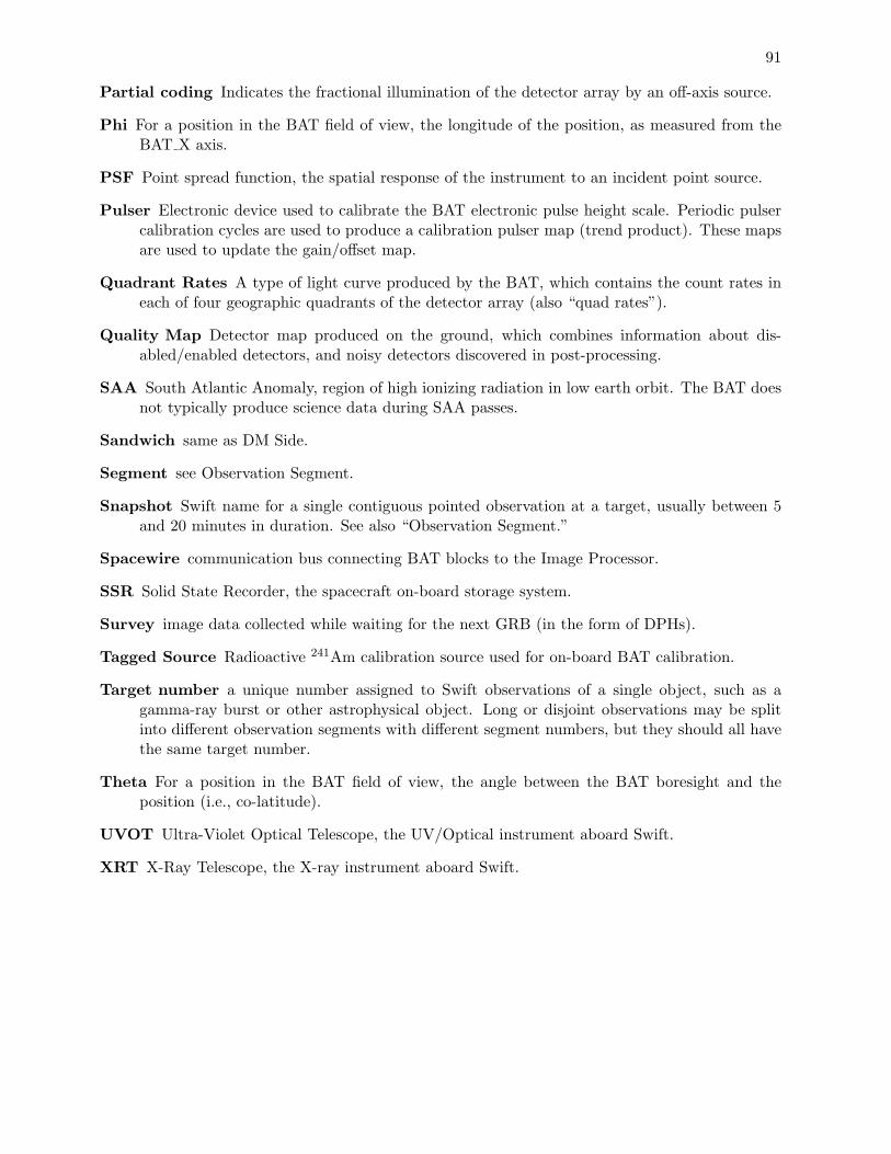
91
Partial coding Indicates the fractional illumination of the detector array by an off-axis source.
Phi For a position in the BAT field of view, the longitude of the position, as measured from theBAT X axis.
PSF Point spread function, the spatial response of the instrument to an incident point source.
Pulser Electronic device used to calibrate the BAT electronic pulse height scale. Periodic pulsercalibration cycles are used to produce a calibration pulser map (trend product). These mapsare used to update the gain/offset map.
Quadrant Rates A type of light curve produced by the BAT, which contains the count rates ineach of four geographic quadrants of the detector array (also “quad rates”).
Quality Map Detector map produced on the ground, which combines information about dis-abled/enabled detectors, and noisy detectors discovered in post-processing.
SAA South Atlantic Anomaly, region of high ionizing radiation in low earth orbit. The BAT doesnot typically produce science data during SAA passes.
Sandwich same as DM Side.
Segment see Observation Segment.
Snapshot Swift name for a single contiguous pointed observation at a target, usually between 5and 20 minutes in duration. See also “Observation Segment.”
Spacewire communication bus connecting BAT blocks to the Image Processor.
SSR Solid State Recorder, the spacecraft on-board storage system.
Survey image data collected while waiting for the next GRB (in the form of DPHs).
Tagged Source Radioactive 241Am calibration source used for on-board BAT calibration.
Target number a unique number assigned to Swift observations of a single object, such as agamma-ray burst or other astrophysical object. Long or disjoint observations may be splitinto different observation segments with different segment numbers, but they should all havethe same target number.
Theta For a position in the BAT field of view, the angle between the BAT boresight and theposition (i.e., co-latitude).
UVOT Ultra-Violet Optical Telescope, the UV/Optical instrument aboard Swift.
XRT X-Ray Telescope, the X-ray instrument aboard Swift.

92 APPENDIX C. BAT ACRONYM AND TERMINOLOGY GLOSSARY
Appendix D
BAT Software Tool Reference
This appendix is for reference. It contains documentation files for all BAT software tasks.
93
94 APPENDIX D. BAT SOFTWARE TOOL REFERENCE
D.1 BATBINEVT
D.1.1 NAME
batbinevt - accumulate BAT event and DPH data into spectra, lightcurves or images
D.1.2 USAGE
batbinevt infile outfile outtype timedel timebinalg energybins
D.1.3 DESCRIPTION
batbinevt computes mask weighted light curves and spectra for BAT event and detector plane his-togram data (DPHs). This tool can use the weights generated by batmaskwtevt or batmaskwtimgto make binned output light curves and spectra. batbinevt can also be used to make raw detectorplane images and histograms, and to rebin raw detector plane histograms in time or energy.
The input event file must normally have been processed first by batmaskwtevt for a particularsource position. Thus, batbinevt will only extract weighted products for one source at a time,although it can compute many time or energy samples.
INPUT FILE TYPES
batbinevt operates on either event data or BAT DPH data. Event data must have the TIME andenergy columns. If weighting is applied, then either the MASK WEIGHT column must be present,or a separate mask weight image file must be supplied.
batbinevt can also read detector plane histograms (DPHs). BAT DPHs have two spatial dimen-sions and one energy dimension. They are produced by the BAT flight software, and also perhapsprevious runs of batbinevt. They must contain an EBOUNDS extension which describes the energybin edges.
OUTPUT FILE TYPES
batbinevt can output several file types. The most common will be
LC standard OGIP light curve (default: weighted=yes, outunits=RATE);
PHA standard OGIP spectrum (type I or II; weighted=yes, outunits=RATE);Output format is determined automatically; if there is one output spectrum then the outputfile is a type I spectrum; otherwise it is type II.
PHA1 standard OGIP spectrum (type I; default: weighted=yes, outunits=RATE);
PHA2 standard OGIP spectrum (type II; default: weighted=yes, outunits=RATE);
D.1. BATBINEVT 95
batbinevt can also output histograms and images:
DPH detector plane histogram; for each temporal integration, a three dimensional histogram ofthe number of counts is constructed with two spatial dimensions (DETX and DETY) andone energy dimension. batbinevt can rebin an existing DPH in time or energy, or generate anew DPH from event data. The EBOUNDS extension describes the energy binning. (default:weighted=no, outunits=COUNTS);
DPI detector plane image; a histogram of the number of counts in two spatial dimensions (DETXand DETY). Each FITS extension contains only one DPI; multiple images are stored inconcatenated FITS extensions. batbinevt can either “flatten” existing DPHs into DPIs, ormake new DPIs from event data. (default: weighted=no, outunits=COUNTS);
DPITAB detector plane image. Images are stored in rows of a FITS binary table (multipleimages in one extension). (default: weighted=no, outunits=COUNTS).
WEIGHTED or UNWEIGHTED?
Applying mask weighting is equivalent to background subtraction. Detectors which are fully shad-owed are assigned a -1 weight, and fully illuminated detectors a +1 weight, and partially illuminateddetectors are assigned an prorated value. Thus, a weighted sum of the counts will automaticallysubtract the background.
The default of the ‘weighted’ parameter depends on the output type.
• light curves and spectra are weighted by default;
• histograms and detector images are not weighted by default.
Users can choose to change the default by setting weighted to “yes” or “no.”
For event data, the default is to take the mask weighting values for each event from theMASK WEIGHT column. This can be overridden by using the maskwt parameter, which givesa mask weight map to be used for all events. [This parameter should not be used for event datataken during slews.] For DPHs, the mask weighting is also specified using the maskwt parameter.
TIME BINNING
The user can choose how to bin the data in time. For “uniform” binning, a non-zero time bin sizeindicates that every time bin should have the same size. A zero time bin size indicates that allinput data should be summed into a single output time bin.
For “gti” binning, the user specifies the desired bins using the gtifile parameter, which is inthe standard GTI format. Adjoining good time intervals are not merged when using this method.The timedel bin size is ignored. Note that the ‘minfracexp’ parameter is always honored. If it isimportant to preserve all requested bins, even if they have zero exposure, then set minfracexp=0.
For “snr” binning, the user specifies a desired signal-to-noise ratio with the snrthresh parameter.When the total signal to noise ratio for a given time bin exceeds the threshold, a new bin is started.The timedel bin size is taken as the maximum bin size before a new bin is started; if timedel=0then there is no maximum.
The “infile” binning method only applies when the input is a DPH. When the binning algorithmis set to “infile,” then the time binning of the input file is preserved in the output file. This may
96 APPENDIX D. BAT SOFTWARE TOOL REFERENCE
be useful, for example, if each DPH row is to be flattened into a detector image, while otherwisepreserving the individual exposures.
The “matchlc” binning method will bin the input data to match an existing light curve. Thelight curve, which is passed in the ‘gtifile’ parameter, must be a standard OGIP light curve filewith enough information to determine the time binning. If the light curve file has a GTI extension,it is ignored. Note that the ‘minfracexp’ parameter is always honored. If it is important to exactlymatch the template light curve time bins, even if they have zero exposure, then set minfracexp=0.
For output light curves, the TIME column may refer to the start or the center of the bin,depending on the setting of the ‘timepixr’ parameter. Output lightcurves also contain the keywordTIMEPIXR which indicates the reference point for light curve time bins. For all other outputtypes, TIME refers to the start of the accumulation time. In some cases, a separate keyword orcolumn named TSTOP or TIME STOP is used to indicate the stop of the accumulation time.
TIME SELECTION
By default, the input file is selected according to its own internal good time intervals, if any arepresent.
Crude time selection can be performed using the tstart and tstop parameters to the task, whichgive the start and stop times of accumulation.
More refined selections can be performed specifying the gtifile parameter. A good time intervalfile (GTI) describes an arbitrary number of intervals by specifying the start and stop times. Theintersection of the input files’ GTIs, the user-provided gtifile, and the user-provided tstart/tstopparameters, are used to select input data by time. For input DPH (survey) data, the time intervalof each input DPH must overlap with the total good time intervals by a large enough amount, andmust never straddle more than one output bin.
The DPH overlap time required is determined by the min dph frac overlap, min dph time overlapand max dph time nonoverlap parameters. Care should be taken when altering the overlap param-eters, especially when the properties of the source and the background are not constant with time.For example, if a source becomes earth-occulted during the DPH, and a corresponding occulta-tion GTI was input to batbinevt, then the background will have the full exposure, but the sourcewill only have a fractional exposure, i.e. the exposure is ambiguous. For exposure purposes, bat-binevt records the full exposure of all DPHs that pass the overlap tests, including any non-overlapintervals. The output GTI, however, retains the user-requested good time intervals.
FLUX UNCERTAINTIES
batbinevt assumes that detector counts are Poisson-distributed, and propagates the errors to theoutput. However, if the input is a modeled background (e.g. from batclean), then the outputuncertainties will be set to zero. This behavior is governed by the HDUCLAS2 keyword in theinput DPH file: modeled background maps should have HDUCLAS2 = ‘PREDICTED’.
D.1.4 PARAMETERS
infile [filename ]
Input file name or names, containing BAT event or DPH data. This may be a comma-delimited list of names, or the name of a text file containing a list of file names, one per line,preceded by an ‘@’ character.
D.1. BATBINEVT 97
outfile [filename ]
Output light curve or spectrum file name.
outtype [string ]
Chooses output format of either light curve (outtype=“LC”), spectrum (outtype=“PHA”,“PHA1”, “PHA2”), detector plane histogram (outtype=“DPH”), detector plane image (out-type=“DPI”), or detetector plane image table (outtype=“DPITAB”). The difference betweenDPI and DPITAB is that DPI output has one detector image per FITS image extension andthe later has one image per FITS row in a single extension.
timedel = 1.0 [real ]
Select a time bin size, in seconds. If time binning is uniform, then a value of timedel=0.0causes the tool to accumulate all data into a single time bin. If time binning algorithm is“snr”, then a non-zero bin size indicates the maximum bin size regardless of the signal tonoise ratio. A zero value of timedel indicates no maximum bin size.
timebinalg = uniform [string ]
One of “uniform”, for uniform binning, “snr”, for constant signal to noise ratio, “gti” for timebinning according to the intervals in the GTI file, “infile” to mimic the input file binning(binned input data only), or “matchlc” to match an existing light curve. Only the firstcharacter of the algorithm type needs to be specified.
energybins = “-” [string ]
Energy bin ranges, expressed as a comma-separated list of floating point number ranges, afile name containing energy bin ranges, INFILE, FILEBINS or CALDB.
Comma-separated list Each bin in the comma-separated list is specified as EMIN1-EMAX1,EMIN2-EMAX2,... (in units of keV). Pulse heights which satisfy EMIN[n] ≤ E< EMAX[n] are considered to be in bin n. If EMIN[n] is missing, then it is assumed tobe 0. If EMAX[n] is missing it is assumed to be the maximum energy. A value of “-”indicates single all-inclusive energy bin. At least one bin must be given to make even alight curve, and bins must not overlap.
File name The name of a FITS file with an EBOUNDS extension (such as a responsematrix), containing columns E MIN and E MAX (in keV), or an ASCII file containinga comma-separated energy bin list as described above.
FILEBINS or INFILE FILEBINS or INFILE indicates that the energy binning of thefirst input file is used. (this only applies when the inputs are DPHs, and the DPH musthave an EBOUNDS extension).
CALDB If CALDB is specified, then the CALDB database is consulted for energy bins. Astandard 4-channel and 80-channel set of binnings is chosen depending on whether theouttype is LC or PHA, respectively. By using CALDB:n, a specific n-channel binningcan be selected (provided it exists in CALDB).
(gtifile = NONE) [string ]
Name of goodtime interval file or time bin file. If the time binning algorithm is “gti” or“matchlc” then this file is used to establish the time bins. Normally, this file is a standardGTI. However, for time binning algorithm “matchlc”, this file should be standard OGIP lightcurve. The user-supplied good times are logically intersected with the good times of the inputfiles (i.e. only overlap portions are used). The default of NONE implies that all good timeintervals from the input files will be used.
98 APPENDIX D. BAT SOFTWARE TOOL REFERENCE
(ecol = PI) [string ]
Column name to use for the energy value. The default is the energy computed in the “PI”column, but it is possible to choose another column name such as “PHA”.
(weighted = INDEF) [string ]
Set to boolean yes or no (or INDEF), depending on whether mask weighting should be appliedto the binning operation. A value of “no” indicates that all counts should be unweighted(unity weight). A value of INDEF depends on outtype. If outtype is LC or PHA, thenINDEF signifies that “yes,” weighting should be applied; for output types DPH, DPI orDPITAB, then INDEF means “no” weighting should be applied.
(outunits = INDEF) [string ]
Set to RATE, COUNTS or INDEF, depending on whether the output histogram units shouldbe “count/s”, “count”, or automatically determined (INDEF). When INDEF is specified,outunit depends on outype. If outtype is LC or PHA, then INDEF signifies “RATE;” foroutput types DPH, DPI or DPITAB, then INDEF means “COUNTS.” Note that not allcombinations are meaningful.
(timepixr = -1.0) [real ]
Determines the reference point of each time bin for light curves only. A value of 0.0 (0.5)indicates that the TIME column refers to the start (center) of each time bin. A specialvalue of -1 (the default) specifies that timepixr=0.0 for uniformly binned light curves andtimepixr=0.5 for non-unformly binned light curves. This parameter does not have any affectfor spectra, images or DPHs.
(maskwt = NONE) [string ]
Mask weight map file. This file should contain a mask weight image for the detector plane,and if given, overrides any mask weighting found in the infile.
(tstart = INDEF) [string ]
Start time of the accumulation, in seconds, expressed in Mission Elapsed Time. Default value(INDEF) implies using the TSTART/TSTOP keywords from the input file.
(tstop = INDEF) [string ]
Stop time of the accumulation, in seconds, expressed in Mission Elapsed Time. Default value(INDEF) implies using the TSTART/TSTOP keywords from the input file.
(snrthresh = 6.0) [real ]
For the constsnr binning method, the signal to noise ratio to require for each time bin. Ifthere is more than one energy bin selected, the threshold refers to the signal to noise ratiofor the sum of all energy bins.
(detmask = “NONE”) [string ]
Name of a detector quality map file. This should be an image file with the same dimensionsas the detector plane map. A pixel value of 0 indicates the detector is enabled for imaging,and a non-zero value indicates disabled. A default value of NONE implies all detectors areon, except for the BAT detector gap regions.
(tcol = “TIME”) [string ]
Name of TIME column in input file.
D.1. BATBINEVT 99
(countscol = “DPH COUNTS”) [string ]
Name of counts column column in input file (column ‘DPH COUNTS’ containing detectorcounts histogram when reading DPH data).
(xcol = “DETX”) [string ]
Name of X column in input file (event data).
(ycol = “DETY”) [string ]
Name of Y column in input file (event data).
(maskwtcol = “MASK WEIGHT”) [string ]
Name of MASK WEIGHT column in input file (event data).
(ebinquant = 0.1) [real ]
Default energy bin quantization, in keV, if none is specified in the input event file. MostBAT input events are quantized with 0.1 keV step sizes using the TSCALn keyword. If nosuch keywords are found, then ebinquant is used. This value should represent the minimumpossible energy bin size of the instrument.
(delzeroes = “NO”) [boolean ]
Delete time bins with zero flux? If yes, then any bin which has no counts, or all counts withzero weights, will be removed from the output. For multi-channel output data types, the timebin will only be deleted if all spatial/spectral bins contain zero. If delzeroes=“NO”, then theoutput may contain bins with zero flux. The error bars will be zero too for those cases, whichmay cause subsequent processing to fail.
(minfracexp = 0.1) [real ]
The minimum fractional exposure. Time bins with smaller fractional exposure are deletedbefore creating the output. To preserve all time bins, even bins with zero exposure, setminfracexp=0. Bins with no exposure will have null COUNTS / RATE.
(min dph frac overlap = 0.999) [real ]
The minimum fractional exposure per individual DPH in the input file. The combined set ofall good time intervals must fractionally overlap with a DPH by at least mindphfracoverlap,or else the DPH row is rejected. The default value of 0.999 allows for a small non-overlap aswell as numerical round-off issues.
(min dph time overlap = 0) [real ]
The minimum time overlap, in seconds, per individual DPH in the input file. The combinedset of all good time intervals must overlap with the DPH by at least mindphtimeoverlapduration, or else the DPH row is rejected. This is also equivalent to a filter on the minimumexposure time per individual DPH. The default value of 0 indicates that any number ofseconds is allowed – but the fractional overlap test (mindphfracoverlap) must also pass.
(max dph time nonoverlap = 0.5) [real ]
The maximum non-overlap time, in seconds, allowed per individual DPH in the input file.After intersecting the combined set of all good times and the individual DPH time interval,the remaining non-overlapping time must be no more than maxdphtimenonoverlap seconds,or else the DPH row is rejected. A larger number is a more liberal acceptance criterium. Thedefault value of 0.5 seconds, allows for a small amount of non-overlap between the good timeintervals and the survey DPH.
100 APPENDIX D. BAT SOFTWARE TOOL REFERENCE
(buffersize = 32768) [integer ]
Size of internal event buffer for processing.
(clobber = NO) [boolean ]
If the output file already exists, then setting “clobber = yes” will cause it to be overwritten.
(chatter = 2) [integer, 0 - 5 ]
Controls the amount of informative text written to standard output. Setting chatter = 1produces a basic summary of the task actions; chatter = 2 (default) additionally prints asummary of input parameters; chatter = 5 prints debugging information.
(history = YES) [boolean ]
If history = YES, then a set of HISTORY keywords will be written to the header of thespecified HDU in the output file to record the value of all the task parameters that were usedto produce the output file.
D.1.5 EXAMPLES
MAKING LIGHT CURVES from EVENT DATA
1. Uniform binning of 0.1 seconds in the 15-195 keV energy range (light curve is weighted i.e.background subtracted)
batbinevt infile.evt outfile.lc LC 0.1 uniform 15-195
(“uniform” binning means uniformly sampled (=0.1s) bins)
2. Two-band light light curve for 15-50 and 50-195 keV (otherwise same as above)
batbinevt infile.evt outfile.lc LC 0.1 uniform 15-50,50-195
(the energy bins can be specified as either an ASCII list or a file name with the energy bins)
3. Binning by constant signal to noise (threshold = 6 sigma)
batbinevt infile.evt outfile.lc LC 0 snr 15-195 snrthresh=6.0
(When the “snr” time binning method is specified, a zero time binning is ignored.)
4. Binning by constant signal to noise (threshold = 6 sigma, maximum bin size of 10 seconds)
batbinevt infile.evt outfile.lc LC 10 snr 15-195 snrthresh=6.0
(When the “snr” time binning method is specified, a non-zero time binning indicates the max-imum bin size that is imposed.)
5. Selecting the times by hand (0.1 second uniform bins, 15-195 keV)
D.1. BATBINEVT 101
batbinevt infile.evt outfile.lc LC 0.1 uniform 15-195 tstart=$START tstop=$STOP
(only include data from $START to $STOP)
6. Applying your own binning (0.1 second uniform bins, 15-195 keV) (must make a Good TimeInterval (GTI) named mygti.gti)
batbinevt infile.evt outfile.lc LC 0.1 gti 15-195 gtifile=mygti.gti
(The “gti” time binning means that the bins are taken from the GTI file. When the timebinning is not “gti” the GTI file is still useful to select data by time.)
7. Unweighted light curve (with no background subtraction)
batbinevt infile.evt outfile.lc LC 0.1 uniform 15-195 weighted=no
(The weighted parameter decides whether mask weighting is applied or not.)
8. Change output units to counts instead of counts/s.
batbinevt infile.evt outfile.lc LC 0.1 uniform 15-195 outunits=count
(The outunits parameter can be either COUNT or RATE.)
MAKING SPECTRA from EVENT DATA
9. Total spectrum, in user-specified energy bins
batbinevt infile.evt outfile.pha PHA 0 uniform 15-25,25-50,50-100,100-195
(A time bin size of 0 means that the entire data set should be accumulated into one totalspectrum.
The energy bins can be specified as either an ASCII list or a file name with the energy bins.With a few bins it is easier to give an ASCII list.)
10. Total spectrum, with energy bins given by EBOUNDS extension in myebounds.fits
batbinevt infile.evt outfile.pha PHA 0 uniform myebounds.fits
(Here the energy bins are given in a file with an EBOUNDS extension.)
11. Spectrum every 100 seconds, using EBOUNDS extension
batbinevt infile.evt outfile.pha PHA 100.0 uniform myebounds.fits
102 APPENDIX D. BAT SOFTWARE TOOL REFERENCE
12. Binning by constant signal to noise (threshold = 6 sigma)
batbinevt infile.evt outfile.pha PHA 0 snr myebounds.fits snrthresh=6.0
(The threshold applies to total spectrum, not any one bin.)
13. Selecting the times by hand
batbinevt infile.evt outfile.pha PHA 0 uniform myebounds.fits tstart=$START tstop=$STOP
(Only includes data from $START to $STOP)
14. Applying your own binning, say from Bayesian Blocks analysis (must make a Good TimeInterval (GTI) named mygti.gti)
batbinevt infile.evt outfile.pha PHA 0 gti myebounds.fits gtifile=mygti.gti
(The “gti” time binning means that the bins are taken from the GTI file. When the timebinning is not “gti” the GTI file is still useful to select data by time.)
15. Unweighted spectrum (with no background subtraction)
batbinevt infile.evt outfile.pha PHA 0 uniform myebounds.fits weighted=no
(The weighted parameter decides whether mask weighting is applied or not.)
16. Change output units to counts instead of counts/s.
batbinevt infile.evt outfile.pha PHA 0 uniform myebounds.fits outunits=count
(The outunits parameter can be either COUNT or RATE.)
MAKING LIGHT CURVES and SPECTRA from DPHs
17. Accumulate mask weighted light curve from DPH (must have generated mask weight imagemaskwt.img for source position of interest)
batbinevt infile.dph outfile.lc LC 0 infile 14.0-194.9 maskwt=maskwt.img
(Note that energy bins must be exact to within 0.1 keV. The “infile” for the time binningalgorithm indicates that the input file binning should be replicated in the output.)
18. Accumulate total mask weighted spectrum from DPH
batbinevt infile.dph outfile.pha PHA 0 uniform infile.dph maskwt=maskwt.img
D.1. BATBINEVT 103
(Note that EBOUNDS extension from infile is used to generate energy bin edges.)
19. Accumulate total mask weighted spectrum with user-designed bins
batbinevt infile.dph outfile.pha PHA 0 gti infile.dph maskwt=maskwt.img
20. Accumulate raw light curve from DPH (no mask weighting)
batbinevt infile.dph outfile.lc LC 0 infile 14.0-194.9 weighted=no
21. Accumulate raw spectrum from DPH (no mask weighting)
batbinevt infile.dph outfile.pha PHA 0 uniform infile.dph weighted=no
MAKING DPHs and DPIs from EVENT DATA
22. Make total DPH from event data
batbinevt infile.evt outfile.dph DPH 0 uniform myebounds.fits
(myebounds.fits should contain the desired energy binning. A time bin size of 0 indicates thatthe total DPH should be constructed.)
23. Make total DPI from event data (15-195 keV)
batbinevt infile.evt outfile.dpi DPI 0 uniform 15-195
24. Make many DPIs from event data (100 second binning)
batbinevt infile.evt outfile.dpi DPI 100 uniform 15-195
(Output file is stored as one DPI per image extension.) One can also use:
batbinevt infile.evt outfile.dpi DPITAB 100 uniform 15-195
(which will put many DPIs into one extension as a table.)
25. Making DPHs from event data is accomplished with this command
batbinevt infile.evt outfile.dph DPH 0 uniform myebounds.fits
(making more than one or two DPHs in this way is not recommended, since it requires a largeamount of computer memory).
104 APPENDIX D. BAT SOFTWARE TOOL REFERENCE
MANIPULATING and FLATTENING DPHs
batbinevt can be used to “flatten” detector plane histograms in various ways.
26. Make total DPH (add all DPH rows into a single DPH row).
batbinevt infile.dph outfile.dph DPH 0 uniform infile.dph
(The energy binning of infile.dph means that the energy binning of the input file is preservedin the output).
27. Make total DPI (add all DPH rows into a single detector image).
batbinevt infile.dph outfile.dpi DPI 0 uniform 14.0-194.9
(Only energies from 14.0-194.9 are kept in the detector image.)
28. Make one DPI for each DPH (flatten by energy)
batbinevt infile.dph outfile.dpi DPITAB 0 infile 14.0-194.9
(“infile” time binning indicates to preserve input file time bins. The output file is a table ofDPIs, one per FITS row). This command creates one DPI per image extension.
batbinevt infile.dph outfile.dpi DPI 0 infile 14.0-194.9
(either is compatible with the batfftimage imaging software)
29. Make new DPHs by collapsing some energy bins. This command makes approximate binsfrom 15-25,25-50,50-100 and 100-200 keV.
batbinevt infile.dph outfile.dph DPH 0 infile 14-26,26-51.1,51.1-101.2,101.2-194.9
(Note energy bins must agree to within 0.1 keV of input binning)
It is not advisable to make more than one full-sized (>80 energy channels) DPH because thememory storage requirements are prohibitive.
D.1.6 SEE ALSO
extractor, batmaskwtevt, batmaskwtimg
D.1.7 LAST MODIFIED
Apr 2007
D.2. BATCELLDETECT 105
D.2 BATCELLDETECT
D.2.1 NAME
batcelldetect - perform source detection using the sliding cell method
D.2.2 USAGE
batcelldetect infile outfile snrthresh
D.2.3 DESCRIPTION
batcelldetect performs source detection on a sky image. The sliding cell method is used to locateregions of the image which are significantly different from the background.
This tool is more appropriate for coded aperture imaging because: (1) it assumes Gaussianfluctuations, not Poissonian; (2) it measures the local background; and (3) it measures the localbackground standard deviation. A source is detected at a pixel if that pixel’s value exceeds thebackground by more than “snrthresh” times the background standard deviation. Users can increasethe significance of a detection and reduce false detections by requiring more than one adjacent pixelexceed the threshold, using the “nadjpix” parameter. The “nullborder” and “bkgpcodethresh”parameters can also be used to exclude false positives near the edge of the image.
The background value is estimated by using a sliding window. The shape of the window iseither circular or square, and the radius (or half-width) is specified by the bkgradius parameter.In determining the background, a circular region at the center of the window is excluded, whoseradius is the srcradius parameter. Thus, the background does not include contamination from thesource region.
In a single iteration, the sliding cell algorithm is less sensitive in a region around bright sources,because the background standard deviation becomes biased. To avoid this, the algorithm can berun in multiple iterations. After each iteration, the detected pixels are removed, and thus the biascan be significantly reduced.
A second stage fits a point spread function to regions of the image where sources are detected.For new sources, this aids in refining the centroid of the source position, as well as in estimatinguncertainties.
The default output is a catalog list of detected sources, plus various statistics about them. Theoutput flux column is either COUNTS or RATE, depending on the input image units. The tool canoptionally output the background map, the background fluctuation map, and a significance map.
IMPORTANT NOTE: if the keepbadsources parameter is ‘YES’, then the output catalogmay contain some sources which failed processing for one reason or another. Information on thesuccess or failure on a source-by-source basis is recorded in the DETECT STATUS column.
The user can also supply an input catalog. Sources in the input catalog, which are within thefield of view of the image, are assumed to be fixed at their known positions, and fitted during
106 APPENDIX D. BAT SOFTWARE TOOL REFERENCE
the PSF-fitting stage for intensity only (unless posfit=NO). Additional detected sources are alsowritten to the output catalog.
This task can operate on multiple images, as produced by batfftimage. If the images varyonly in their energy range, and are otherwise identical in their coordinate systems and exposures,then the ‘vectorflux’ parameter can be set to YES. When vectorflux=YES, each source has onlyone catalog row, and multiple fluxes are recorded in a vector table cell. When vectorflux=NO, asource will appear multiple times in the catalog, with a single flux in each entry. Note that if theinput images do not match exactly their coordinate system or exposures, then you must specifyvectorflux=NO.
To avoid spurious detections at the edge of the field of view, a partial coding threshold can bespecified (see ‘pcodefile’ and ‘pcodethresh’). If a partial coding map is provided, then by defaultsources must be at least 1% coded.
This routine uses a relatively straightforward brute-force convolution by FFT to compute thesliding-cell averages. Users should have a about a factor of eight more memory than the size of theimage.
Fitting For Position and Flux
batcelldetect has several options to fit the positions and fluxes of sources. Newly detected andpreviously known sources are treated differently. By default, the positions of newly detected sourcesare allowed to vary and the those of previously known sources are held fixed. This behavior dependson the input parameters and the input catalog.
The following behaviors are possible:
srcfit=NO Perform source detection only. The positions and fluxes for all sources are not fit. Fornew sources, the positions are taken from the source detection stage. For previously knownsources, the values are transferred from the input catalog completely unchanged.
srcfit=YES; posfit=NO (DEFAULT) Hold the position of known sources fixed, but fit for thepositions of new sources. The fluxes of all sources are fitted.
srcfit=YES; posfit=YES; posfitwindow=0.0 Fit for the positions of all sources. The posi-tions of known sources are allowed to vary within a window which is 3 times the ERR RADvalue from the input catalog. Thus, if ERR RAD = 0, the position is held fixed. Specialcases: if an individual value of ERR RAD is null, the position of that source is allowed tovary. If the ERR RAD column is missing entirely, the positions are assumed to be fixed. Thefluxes of all sources are fitted.
srcfit=YES; posfit=YES; posfitwindow > 0 As above, except the positions of known sourcesare allowed to vary by ± 3*ERR RAD or ± posfitwindow, whichever is larger.
As of May 2007, the BAT team recommends using the GAUSSIAN point spread function(FWHM=0.37413) for all BAT data throughout the mission. The previous recommendation to usethe “PYRAMID” shape was not correct.
D.2.4 CATALOG OUTPUT
The output catalog contains the following columns. Other input columns are copied to the outputunchanged. For new sources entries, the row is filled with null value before writing batcelldetect-derived quantities.
D.2. BATCELLDETECT 107
Note that while the input catalog is only required to have the NAME, RA OBJ and DEC OBJcolumns, they must have the units and dimensions listed below. Any input catalog columns thatmatch the list below, must also have the specified units.
The data type should be either “D” (double) or “J” (integer); the NAME column can be up to a30-character string. The word “Vector” indicates which output catalog columns will be a vector ifvectflux=YES and multiple images are analyzed.
TIME Start time of image (Mission Elapsed Time). Type=D, Unit=s.
TIME STOP Stop time of image (Mission Elapsed Time). Type=D, Unit=s.
EXPOSURE EXPOSURE time of image. Type=D, Unit=s.
CATNUM Catalog identification number (copied from input catalog). Type=J.
NAME Source name (copied from input catalog). Type=30A (string).
IMX IMX Tangent plane coordinate (instrument X). Type=D.
IMY IMY Tangent plane coordinate (instrument Y). Type=D.
IMX ERR IMX formal uncertainty. Type=D.
IMY ERR IMY formal uncertainty. Type=D.
IMXPIX IMX pixel coordinate (instrument X). Type=D.
IMYPIX IMY pixel coordinate (instrument Y). Type=D.
RA OBJ / GLON OBJ Source celestial longitude (equatorial or galactic). Type=D, Unit=deg.
DEC OBJ / GLAT OBJ Source celestial latitude (equatorial or galactic). Type=D, Unit=deg.
RA OBJ ERR / GLON OBJ ERR Source celestial longitude formal uncertainty (1 sigma).Type=D, Unit=deg.
DEC OBJ ERR / GLAT OBJ ERR Source celestial latitude formal uncertainty (1 sigma).Type=D, Unit=deg.
ERR RAD Estimated error radius (formal; 1 sigma). Type=D, Unit=deg.
IMX FWHM Instrumental PSF X full width at half-max (tangent plane coords). Type=D.
IMY FWHM Instrumental PSF Y full width at half-max (tangent plane coords). Type=D.
IMX FWHM ERR Instrumental PSF X FWHM formal uncertainty (1 sigma). Type=D.
IMY FWHM ERR Instrumental PSF Y FWHM formal uncertainty (1 sigma). Type=D.
THETA Source angle from instrumental boresight. Type=D, Unit=deg.
PHI Source instrumental longitude. Type=D, Unit=deg.
GRMCLON BAT simulator longitude. Type=D, Unit=deg.
GRMCLAT BAT simulator latitude. Type=D, Unit=deg.
108 APPENDIX D. BAT SOFTWARE TOOL REFERENCE
RATE Source count rate (units from image)RATE is used if the image has rate-like units. Type=D, Vector.
RATE ERR Source count rate formal uncertainty (1 sigma; units from image). Type=D, Vector.
CENT RATE Source count rate derived from the pixel nearest to the catalog position. Type=D,Vector.
COUNTS Source counts (units from image)COUNTS is used if the image does not have rate-like units. Type=D, Vector.
COUNTS ERR Source counts formal uncertainty (1 sigma; units from image). Type=D, Vector.
CENT COUNTS Source counts derived from the pixel nearest to the catalog position. Type=D,Vector.
BKG Local background intensity (units from image). Type=D, Vector.
BKG ERR Local background intensity formal uncertainty (1 sigma; units from image). Type=D,Vector.
BKG VAR Local background standard deviation (units from image). Type=D, Vector.
SNR Source signal to noise ratio (defined as RATE/BKG VAR). Type=D, Vector.
NPIXSOU Number of valid pixels in the source window. Type=J, Unit=pixel.
NPIXBKG Number of valid pixels in the background window. Type=J, Unit=pixel.
DETECT METHOD Method used for source detection:1=Cell detection2=PSF fit.Type=J.
CHI2 Chi2 value in PSF fit. Type=D, Vector.
DOF Number of degrees of freedom in PSF fit. Type=D, Vector.
CHI2 NU Reduced Chi2 value in PSF fit. Type=D, Vector.
DETECT STATUS Source detection status code; entries with non-zero DETECT STATUS aredeleted when keepbadsources=‘NO’; One of:0=OK;-1=Too many pixels detected;-2=No pixels detected;-3=Source touches border of image;-4=Source error radius did not fit in source window.-5=PSF fit failed (source was likely out of bounds)Type=J.
CONSTRAINT FLAG PSF fitting constraint flag; Describes which parameters of the PSFmodel were fixed; Sum of:1=IMX fixed;2=IMY fixed;4=COUNTS/RATE fixed;8=PSF width fixed.Type=J.
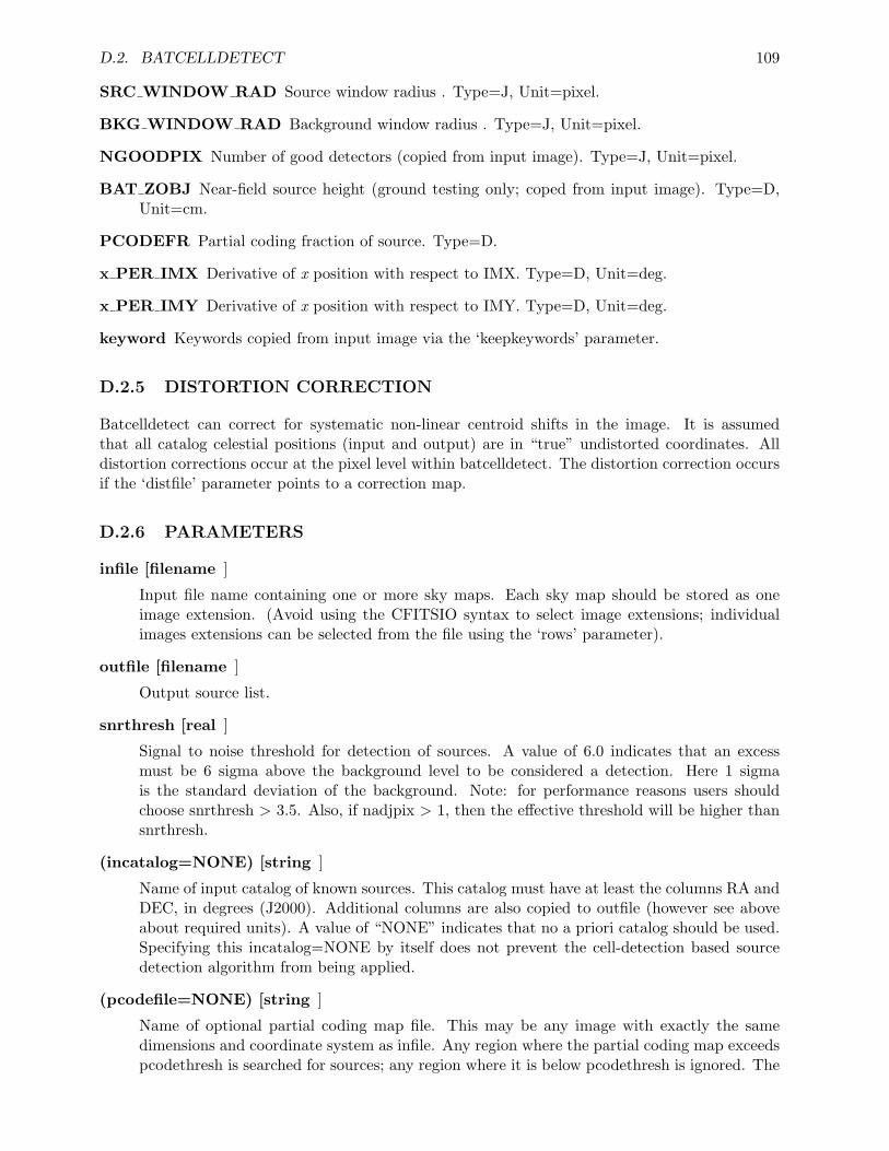
D.2. BATCELLDETECT 109
SRC WINDOW RAD Source window radius . Type=J, Unit=pixel.
BKG WINDOW RAD Background window radius . Type=J, Unit=pixel.
NGOODPIX Number of good detectors (copied from input image). Type=J, Unit=pixel.
BAT ZOBJ Near-field source height (ground testing only; coped from input image). Type=D,Unit=cm.
PCODEFR Partial coding fraction of source. Type=D.
x PER IMX Derivative of x position with respect to IMX. Type=D, Unit=deg.
x PER IMY Derivative of x position with respect to IMY. Type=D, Unit=deg.
keyword Keywords copied from input image via the ‘keepkeywords’ parameter.
D.2.5 DISTORTION CORRECTION
Batcelldetect can correct for systematic non-linear centroid shifts in the image. It is assumedthat all catalog celestial positions (input and output) are in “true” undistorted coordinates. Alldistortion corrections occur at the pixel level within batcelldetect. The distortion correction occursif the ‘distfile’ parameter points to a correction map.
D.2.6 PARAMETERS
infile [filename ]
Input file name containing one or more sky maps. Each sky map should be stored as oneimage extension. (Avoid using the CFITSIO syntax to select image extensions; individualimages extensions can be selected from the file using the ‘rows’ parameter).
outfile [filename ]
Output source list.
snrthresh [real ]
Signal to noise threshold for detection of sources. A value of 6.0 indicates that an excessmust be 6 sigma above the background level to be considered a detection. Here 1 sigmais the standard deviation of the background. Note: for performance reasons users shouldchoose snrthresh > 3.5. Also, if nadjpix > 1, then the effective threshold will be higher thansnrthresh.
(incatalog=NONE) [string ]
Name of input catalog of known sources. This catalog must have at least the columns RA andDEC, in degrees (J2000). Additional columns are also copied to outfile (however see aboveabout required units). A value of “NONE” indicates that no a priori catalog should be used.Specifying this incatalog=NONE by itself does not prevent the cell-detection based sourcedetection algorithm from being applied.
(pcodefile=NONE) [string ]
Name of optional partial coding map file. This may be any image with exactly the samedimensions and coordinate system as infile. Any region where the partial coding map exceedspcodethresh is searched for sources; any region where it is below pcodethresh is ignored. The
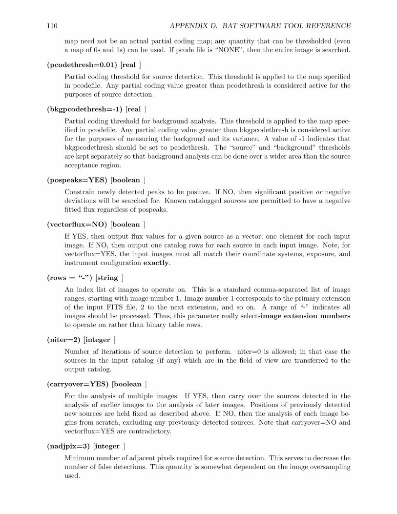
110 APPENDIX D. BAT SOFTWARE TOOL REFERENCE
map need not be an actual partial coding map; any quantity that can be thresholded (evena map of 0s and 1s) can be used. If pcode file is “NONE”, then the entire image is searched.
(pcodethresh=0.01) [real ]
Partial coding threshold for source detection. This threshold is applied to the map specifiedin pcodefile. Any partial coding value greater than pcodethresh is considered active for thepurposes of source detection.
(bkgpcodethresh=-1) [real ]
Partial coding threshold for background analysis. This threshold is applied to the map spec-ified in pcodefile. Any partial coding value greater than bkgpcodethresh is considered activefor the purposes of measuring the backgroud and its variance. A value of -1 indicates thatbkgpcodethresh should be set to pcodethresh. The “source” and “background” thresholdsare kept separately so that background analysis can be done over a wider area than the sourceacceptance region.
(pospeaks=YES) [boolean ]
Constrain newly detected peaks to be positve. If NO, then significant positive or negativedeviations will be searched for. Known catalogged sources are permitted to have a negativefitted flux regardless of pospeaks.
(vectorflux=NO) [boolean ]
If YES, then output flux values for a given source as a vector, one element for each inputimage. If NO, then output one catalog rows for each source in each input image. Note, forvectorflux=YES, the input images must all match their coordinate systems, exposure, andinstrument configuration exactly.
(rows = “-”) [string ]
An index list of images to operate on. This is a standard comma-separated list of imageranges, starting with image number 1. Image number 1 corresponds to the primary extensionof the input FITS file, 2 to the next extension, and so on. A range of “-” indicates allimages should be processed. Thus, this parameter really selectsimage extension numbersto operate on rather than binary table rows.
(niter=2) [integer ]
Number of iterations of source detection to perform. niter=0 is allowed; in that case thesources in the input catalog (if any) which are in the field of view are transferred to theoutput catalog.
(carryover=YES) [boolean ]
For the analysis of multiple images. If YES, then carry over the sources detected in theanalysis of earlier images to the analysis of later images. Positions of previously detectednew sources are held fixed as described above. If NO, then the analysis of each image be-gins from scratch, excluding any previously detected sources. Note that carryover=NO andvectorflux=YES are contradictory.
(nadjpix=3) [integer ]
Minimum number of adjacent pixels required for source detection. This serves to decrease thenumber of false detections. This quantity is somewhat dependent on the image oversamplingused.
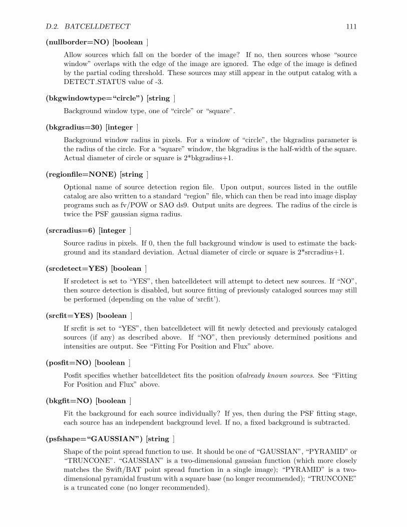
D.2. BATCELLDETECT 111
(nullborder=NO) [boolean ]
Allow sources which fall on the border of the image? If no, then sources whose “sourcewindow” overlaps with the edge of the image are ignored. The edge of the image is definedby the partial coding threshold. These sources may still appear in the output catalog with aDETECT STATUS value of -3.
(bkgwindowtype=“circle”) [string ]
Background window type, one of “circle” or “square”.
(bkgradius=30) [integer ]
Background window radius in pixels. For a window of “circle”, the bkgradius parameter isthe radius of the circle. For a “square” window, the bkgradius is the half-width of the square.Actual diameter of circle or square is 2*bkgradius+1.
(regionfile=NONE) [string ]
Optional name of source detection region file. Upon output, sources listed in the outfilecatalog are also written to a standard “region” file, which can then be read into image displayprograms such as fv/POW or SAO ds9. Output units are degrees. The radius of the circle istwice the PSF gaussian sigma radius.
(srcradius=6) [integer ]
Source radius in pixels. If 0, then the full background window is used to estimate the back-ground and its standard deviation. Actual diameter of circle or square is 2*srcradius+1.
(srcdetect=YES) [boolean ]
If srcdetect is set to “YES”, then batcelldetect will attempt to detect new sources. If “NO”,then source detection is disabled, but source fitting of previously cataloged sources may stillbe performed (depending on the value of ‘srcfit’).
(srcfit=YES) [boolean ]
If srcfit is set to “YES”, then batcelldetect will fit newly detected and previously catalogedsources (if any) as described above. If “NO”, then previously determined positions andintensities are output. See “Fitting For Position and Flux” above.
(posfit=NO) [boolean ]
Posfit specifies whether batcelldetect fits the position ofalready known sources. See “FittingFor Position and Flux” above.
(bkgfit=NO) [boolean ]
Fit the background for each source individually? If yes, then during the PSF fitting stage,each source has an independent background level. If no, a fixed background is subtracted.
(psfshape=“GAUSSIAN”) [string ]
Shape of the point spread function to use. It should be one of “GAUSSIAN”, “PYRAMID” or“TRUNCONE”. “GAUSSIAN” is a two-dimensional gaussian function (which more closelymatches the Swift/BAT point spread function in a single image); “PYRAMID” is a two-dimensional pyramidal frustum with a square base (no longer recommended); “TRUNCONE”is a truncated cone (no longer recommended).
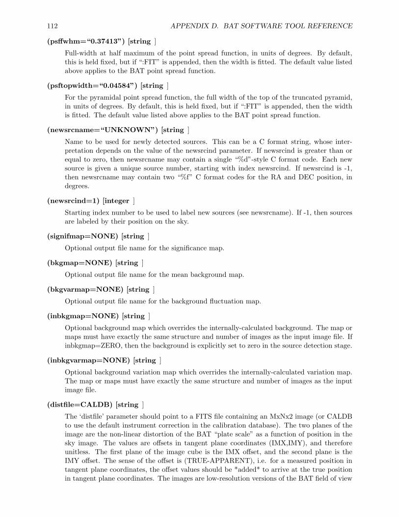
112 APPENDIX D. BAT SOFTWARE TOOL REFERENCE
(psffwhm=“0.37413”) [string ]
Full-width at half maximum of the point spread function, in units of degrees. By default,this is held fixed, but if “:FIT” is appended, then the width is fitted. The default value listedabove applies to the BAT point spread function.
(psftopwidth=“0.04584”) [string ]
For the pyramidal point spread function, the full width of the top of the truncated pyramid,in units of degrees. By default, this is held fixed, but if “:FIT” is appended, then the widthis fitted. The default value listed above applies to the BAT point spread function.
(newsrcname=“UNKNOWN”) [string ]
Name to be used for newly detected sources. This can be a C format string, whose inter-pretation depends on the value of the newsrcind parameter. If newsrcind is greater than orequal to zero, then newsrcname may contain a single “%d”-style C format code. Each newsource is given a unique source number, starting with index newsrcind. If newsrcind is -1,then newsrcname may contain two “%f” C format codes for the RA and DEC position, indegrees.
(newsrcind=1) [integer ]
Starting index number to be used to label new sources (see newsrcname). If -1, then sourcesare labeled by their position on the sky.
(signifmap=NONE) [string ]
Optional output file name for the significance map.
(bkgmap=NONE) [string ]
Optional output file name for the mean background map.
(bkgvarmap=NONE) [string ]
Optional output file name for the background fluctuation map.
(inbkgmap=NONE) [string ]
Optional background map which overrides the internally-calculated background. The map ormaps must have exactly the same structure and number of images as the input image file. Ifinbkgmap=ZERO, then the background is explicitly set to zero in the source detection stage.
(inbkgvarmap=NONE) [string ]
Optional background variation map which overrides the internally-calculated variation map.The map or maps must have exactly the same structure and number of images as the inputimage file.
(distfile=CALDB) [string ]
The ‘distfile’ parameter should point to a FITS file containing an MxNx2 image (or CALDBto use the default instrument correction in the calibration database). The two planes of theimage are the non-linear distortion of the BAT “plate scale” as a function of position in thesky image. The values are offsets in tangent plane coordinates (IMX,IMY), and thereforeunitless. The first plane of the image cube is the IMX offset, and the second plane is theIMY offset. The sense of the offset is (TRUE-APPARENT), i.e. for a measured position intangent plane coordinates, the offset values should be *added* to arrive at the true positionin tangent plane coordinates. The images are low-resolution versions of the BAT field of view
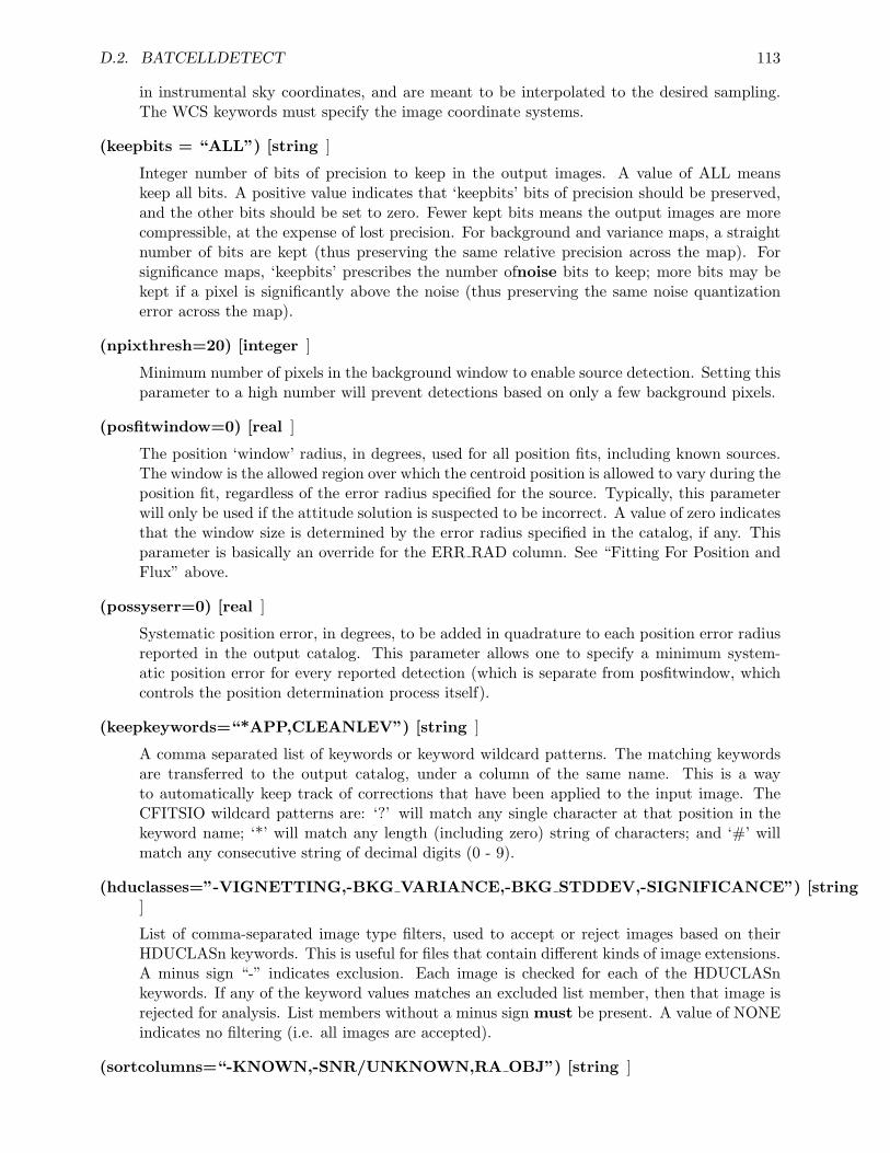
D.2. BATCELLDETECT 113
in instrumental sky coordinates, and are meant to be interpolated to the desired sampling.The WCS keywords must specify the image coordinate systems.
(keepbits = “ALL”) [string ]
Integer number of bits of precision to keep in the output images. A value of ALL meanskeep all bits. A positive value indicates that ‘keepbits’ bits of precision should be preserved,and the other bits should be set to zero. Fewer kept bits means the output images are morecompressible, at the expense of lost precision. For background and variance maps, a straightnumber of bits are kept (thus preserving the same relative precision across the map). Forsignificance maps, ‘keepbits’ prescribes the number ofnoise bits to keep; more bits may bekept if a pixel is significantly above the noise (thus preserving the same noise quantizationerror across the map).
(npixthresh=20) [integer ]
Minimum number of pixels in the background window to enable source detection. Setting thisparameter to a high number will prevent detections based on only a few background pixels.
(posfitwindow=0) [real ]
The position ‘window’ radius, in degrees, used for all position fits, including known sources.The window is the allowed region over which the centroid position is allowed to vary during theposition fit, regardless of the error radius specified for the source. Typically, this parameterwill only be used if the attitude solution is suspected to be incorrect. A value of zero indicatesthat the window size is determined by the error radius specified in the catalog, if any. Thisparameter is basically an override for the ERR RAD column. See “Fitting For Position andFlux” above.
(possyserr=0) [real ]
Systematic position error, in degrees, to be added in quadrature to each position error radiusreported in the output catalog. This parameter allows one to specify a minimum system-atic position error for every reported detection (which is separate from posfitwindow, whichcontrols the position determination process itself).
(keepkeywords=“*APP,CLEANLEV”) [string ]
A comma separated list of keywords or keyword wildcard patterns. The matching keywordsare transferred to the output catalog, under a column of the same name. This is a wayto automatically keep track of corrections that have been applied to the input image. TheCFITSIO wildcard patterns are: ‘?’ will match any single character at that position in thekeyword name; ‘*’ will match any length (including zero) string of characters; and ‘#’ willmatch any consecutive string of decimal digits (0 - 9).
(hduclasses=”-VIGNETTING,-BKG VARIANCE,-BKG STDDEV,-SIGNIFICANCE”) [string]
List of comma-separated image type filters, used to accept or reject images based on theirHDUCLASn keywords. This is useful for files that contain different kinds of image extensions.A minus sign “-” indicates exclusion. Each image is checked for each of the HDUCLASnkeywords. If any of the keyword values matches an excluded list member, then that image isrejected for analysis. List members without a minus sign must be present. A value of NONEindicates no filtering (i.e. all images are accepted).
(sortcolumns=“-KNOWN,-SNR/UNKNOWN,RA OBJ”) [string ]
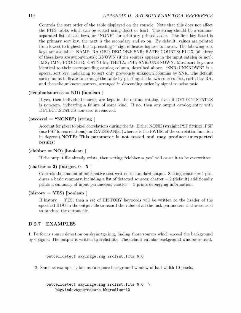
114 APPENDIX D. BAT SOFTWARE TOOL REFERENCE
Controls the sort order of the table displayed on the console. Note that this does not affectthe FITS table, which can be sorted using ftsort or fsort. The string should be a comma-separated list of sort keys, or “NONE” for arbitrary printed order. The first key listed isthe primary sort key, the next is the secondary and so on. By default, values are printedfrom lowest to highest, but a preceding ‘-’ sign indicates highest to lowest. The following sortkeys are available: NAME; RA OBJ; DEC OBJ; SNR; RATE; COUNTS; FLUX (all threeof these keys are synonymous); KNOWN (if the sources appears in the input catalog or not);IMX; IMY; PCODEFR; CATNUM; THETA; PHI; SNR/UNKNOWN. Most sort keys areidentical to their corresponding catalog column, described above. “SNR/UNKNOWN” is aspecial sort key, indicating to sort only previously unknown columns by SNR. The defaultsortcolumns indicate to arrange the table by printing the known sources first, sorted by RA,and then the unknown sources, arranged in descending order by signal to noise ratio.
(keepbadsources = NO) [boolean ]
If yes, then individual sources are kept in the output catalog, even if DETECT STATUSis non-zero, indicating a failure of some kind. If no, then any output catalog entry withDETECT STATUS non-zero is removed.
(ptcorrel = “NONE”) [string ]
Account for pixel to pixel correlations during the fit. Either NONE (straight PSF fitting); PSF(use PSF for correlations); or GAUSSIAN[x] (where x is the FWHM of the correlation functionin degrees).NOTE: This parameter is not tested and may produce unexpectedresults!
(clobber = NO) [boolean ]
If the output file already exists, then setting “clobber = yes” will cause it to be overwritten.
(chatter = 2) [integer, 0 - 5 ]
Controls the amount of informative text written to standard output. Setting chatter = 1 pro-duces a basic summary, including a list of detected sources; chatter = 2 (default) additionallyprints a summary of input parameters; chatter = 5 prints debugging information.
(history = YES) [boolean ]
If history = YES, then a set of HISTORY keywords will be written to the header of thespecified HDU in the output file to record the value of all the task parameters that were usedto produce the output file.
D.2.7 EXAMPLES
1. Performs source detection on skyimage.img, finding those sources which exceed the backgroundby 6 sigma. The output is written to srclist.fits. The default circular background window is used.
batcelldetect skyimage.img srclist.fits 6.0
2. Same as example 1, but use a square background window of half-width 10 pixels.
batcelldetect skyimage.img srclist.fits 6.0 \bkgwindowtype=square bkgradius=10
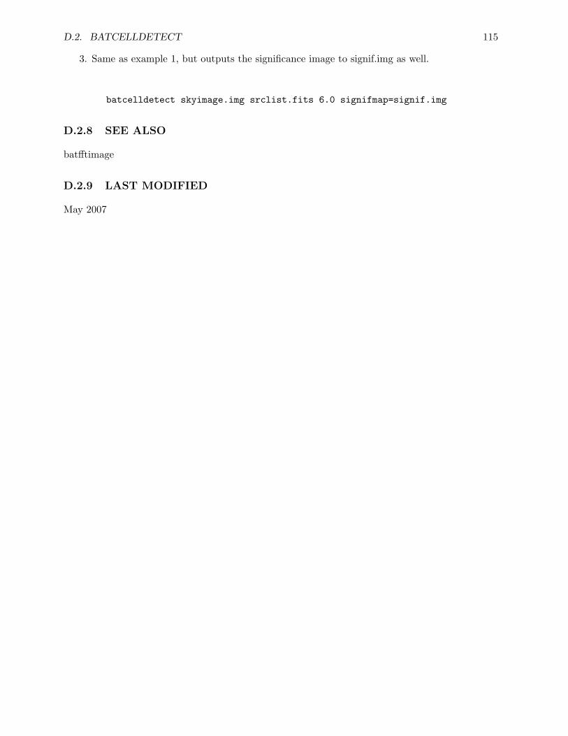
D.2. BATCELLDETECT 115
3. Same as example 1, but outputs the significance image to signif.img as well.
batcelldetect skyimage.img srclist.fits 6.0 signifmap=signif.img
D.2.8 SEE ALSO
batfftimage
D.2.9 LAST MODIFIED
May 2007
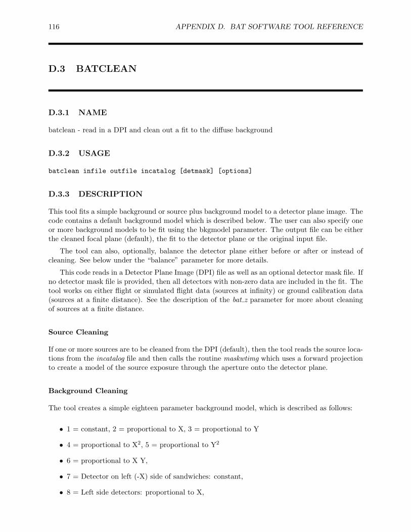
116 APPENDIX D. BAT SOFTWARE TOOL REFERENCE
D.3 BATCLEAN
D.3.1 NAME
batclean - read in a DPI and clean out a fit to the diffuse background
D.3.2 USAGE
batclean infile outfile incatalog [detmask] [options]
D.3.3 DESCRIPTION
This tool fits a simple background or source plus background model to a detector plane image. Thecode contains a default background model which is described below. The user can also specify oneor more background models to be fit using the bkgmodel parameter. The output file can be eitherthe cleaned focal plane (default), the fit to the detector plane or the original input file.
The tool can also, optionally, balance the detector plane either before or after or instead ofcleaning. See below under the “balance” parameter for more details.
This code reads in a Detector Plane Image (DPI) file as well as an optional detector mask file. Ifno detector mask file is provided, then all detectors with non-zero data are included in the fit. Thetool works on either flight or simulated flight data (sources at infinity) or ground calibration data(sources at a finite distance). See the description of the bat z parameter for more about cleaningof sources at a finite distance.
Source Cleaning
If one or more sources are to be cleaned from the DPI (default), then the tool reads the source loca-tions from the incatalog file and then calls the routine maskwtimg which uses a forward projectionto create a model of the source exposure through the aperture onto the detector plane.
Background Cleaning
The tool creates a simple eighteen parameter background model, which is described as follows:
• 1 = constant, 2 = proportional to X, 3 = proportional to Y
• 4 = proportional to X2, 5 = proportional to Y2
• 6 = proportional to X Y,
• 7 = Detector on left (-X) side of sandwiches: constant,
• 8 = Left side detectors: proportional to X,
D.3. BATCLEAN 117
• 9 = Detector on right (+X) side of sandwiches: constant,
• 10 = Right side detectors: proportional to X,
• 11 = Detectors on front (-Y) side of sandwiches: constant,
• 12 = Front side detectors: proportional to Y,
• 13 = Detectors on back (+Y) side of sandwiches: constant,
• 14 = Back side detectors: proportional to Y,
The code creates a background exposure map based on the model above (which can be optionallyoutput using the backexp parameter). In addition the user can supply his own background modelto be fit in addition to or in place of the standard background model.
The tool then uses a singular value decomposition method to fit the source exposure andbackground exposure maps to the data from the DPI. The coefficients from the fit are writtento the output file as keywords.
The fit coefficients are then used to create a model background DPI. This is then subtractedfrom the original input DPI to produce a cleaned DPI. The code writes keywords giving the fitparameter for each background parameter (simple plus user supplied) and source parameter that isfit. These keywords are BGPARnn for background and SRPARnn for sources. The number nn goesfrom 0 to the total number of parameters, starting with the hard-coded background parameters.
D.3.4 PARAMETERS
infile [filename ]
Input file name. The name of the input DPI file. This is expected to be an image arraywith dimensions equal to the number of detector columns by the number of detector rows(set to 286 X 173). If there are multiple BAT DPI image extensions then all are cleaned andmultiple cleaned images are written to the output file.
outfile [filename ]
Output file name. This will be written in the DPI format. The default is to write out thecleaned image, but other outputs can be selected using the outversion parameter. Precedethe output file name with an exclamation point, “!”, (or “\ !” on the Unix command line),to overwrite a preexisting file with the same name (or set the clobber parameter to YES).
incatalog [filename ]
Input source catalog. The format of the catalog file is that output by the BAT tool bat-celldetect. In particular the catalog must contain columns “IMX,” “IMY,” “CATNUM,” (or“SOURCE ID”), “NAME,” and “SNR.” The tool reads the source position in BAT imagecoordinates from this file and uses the source position to forward project a model of thesource flux onto the focal plane. This parameter may be omitted or set to “NONE” if onlybackground cleaning is required (i.e., the srcclean parameter set to “NO”). The SRPARnnkeywords giving the fit parameter for each source contain the source name in the commentsfield. Allowed extension names for incatalog are “BAT CATALOG” (default of batcelldetect),“TRIG SOURCE” (BAT on-board catalogs) and “INPUT CATALOG.”
118 APPENDIX D. BAT SOFTWARE TOOL REFERENCE
(aperture) [filename ]
Aperture file. The default is the aperture file in the CALDB area. This parameter maybe omitted or set to “NONE” if only background cleaning is required (i.e., the srccleanparameter set to “NO”). If several aperture types are available in the CALDB, the user canspecify CALDB:apertype. Valid values of apertype are currently: FLUX or DETECTION,for apertures optimized for flux reproducibility or detection sensitivity, respectively.
(detmask) = “NONE” [filename ]
Name of a detector mask file. This should be an image file with the same dimensions as thefocal plane map. A pixel value of 0 indicates the detector is enabled for imaging, and a valueof 1 indicates disabled, noisy, or otherwise selected for elimination from fits. A default valueof NONE implies all detectors are on, except for the BAT detector gap regions.
• It is strongly recommended to use a detector mask file if one is available. The quality of thefit, especially to calibration data is greatly improved if only working detectors are includedin the fits.
(wtmapin) = “NONE” [filename ]
Name of an input error map. This is used to provide weights for the fitting in case one iscleaning a DPI which does not have Poisson statistics (such as an already cleaned DPI). Thetypical sequence would be to create an error map using the wtmapout parameter on the firstcleaning and then read this error map in on the second cleaning. If an already cleaned imageis cleaned without an input error map than uniform weighting is used.
(wtmapout) = “NONE” [filename ]
Name of an output error map. If a filename is specified then the tool writes out a DPIcontaining the calculated weights for each detector. This can be used on subsequent cleaningsas the input wtmapin error map.
(backexp) = “NONE” [filename ]
If the name of a file is given here, then the background model will be output to this file. Theformat is a binary table with one column for each model parameter. The data is written inDPH format, or as a 286 X 173 element array, one number per detector. This table gives themodel which was fit to the data, not the actual fit to the data. The final column in the tableis the covariance matrix from the fit.
(bat z) = 0 [real ]
This is the z-component of the distance to the source in BAT Z coordinates (the verticaldistance of the source from the origin of the BAT coordinate system). This parameter isignored if srcclean = “NO.” If the incatalog contains a BAT Z keyword, then the value of thekeyword is used and the value of the bat z parameter is not used. Note that the default valueof 0 corresponds to a source at infinity.
(bkgmodel) = “simple” [string ]
This optional parameter indicates the background model to be fit. Currently only two modelsare hard coded: the simple model which is the 14 parameter fit described above and an evensimpler test model which was used in testing the fit procedures. As more sophisticatedbackground models are developed, they will be incorporated into the code.
D.3. BATCLEAN 119
• The user can also use this parameter to supply a file or list of files containing user-developedbackground models to be fit. This can be input as either a comma-separated list of modelfiles or a text file (preceded by the “@” symbol) containing a list of input model files, one perline. These model files must be image files in the same format as a BAT DPI (286 columnsby 173 rows). There are no required keywords. If a model file is not found or is not animage file, the code will ignore it. The comment fields of the BGPARnn keywords containthe model names. If an optional MODNAME is supplied, then its value becomes the modelname in the comment field. If this keyword is not present, then the model name is the nameof the file (not including the path). The default behavior of the code is to fit the simplemodel in addition to any user supplied models. The user does not need to also include thestring “simple” in the bkgmodel parameter list. If, however, the user wishes to fit ONLY theuser-supplied models and not the simple model, then he can request this by adding the string“useronly” to the bkgmodel parameter list. See examples below. Finally, it is possible not tofit any model at all, but simply to balance the array (using the balance parameter below. Todo this set bkgmodel=none. Note that if the user selects outversion=“fit” or “bkgfit”, thenno balancing is performed regardless of the value of the balanceparameter.
(srcclean) = “YES” [boolean ]
Determines whether sources are cleaned from the input DPI or only background. If thisparameter is “YES,” then an incatalog andaperture file must be supplied.
(cleansnr) = 6.0 [real ]
Only sources with a signal-to-noise ratio as read from the incatalog higher than this value arecleaned from the DPI. If no sources have a signal-to-noise ratio above the cleansnrvalue, thenonly the background will be cleaned.
(snrcol = “SNR”) [string ]
Name of catalog column to be used with ‘cleansnr’ for signal to noise thresholding. By defaultit is “SNR”, but any column can be used to trigger cleaning.
(ignore) = “UNKNOWN” [string ]
Unless this parameter is set to “NONE” or “none,” the cleaning code will not clean anysource in incatalog whose NAME matches theignore string. The user can either specify aparticular source name, the strings “IGNORE” or “NONE”, or the name of a file (precededby “@”). If a file name is supplied, then the file must contain a list of sources to be ignored,once source per line. Note that source names to be ignored must match exactly (includingspaces, capitalization, etc.) the names in the catalog.
(balance) = “none” [string ]
Unless this parameter is set to “NONE” or “none,” the cleaning code will, after cleaning,also balance the entire array or subsets of the array as specified below. Balancing meanssubtracting the mean for a set of detectors from the values for that set of detectors. In otherwords, it sets the average for the detectors to zero. If a detector mask (detmask) is given,then only non-masked detectors are included in the balancing.
• The balancing that is requested is given by supplied a comma-separated list of any or all ofthe following values. The balance is performed in the order in which the values are listed.Balancing is not commutative, so order is significant. Allowed balance values:
– none: No balancing.
120 APPENDIX D. BAT SOFTWARE TOOL REFERENCE
– All: The entire array is balanced (1 balancing of 32768 detectors).
– Module: Each of the 256 detector modules is separately balanced.
– InOut: Each module has its inner detectors balanced and in separate operations, itsouter detectors balanced.
– Edges: Each module has only its outer (or edge) detectors balanced.
– LongEdges: There are 32 balancings of the long edges of all modules in a row across thearray.
– ShortEdges: There are 32 balancings of the short edges of all modules in a column acrossthe array.
– flight: Reproduce the flight code balancing, by doing first the Edges, then the InOutbalancing.
There is further illumination of the balancing in the comments in the code.
(balfirst) = “no” [boolean ]
Normally, balancing is done after cleaning. However, by setting this parameter to “yes” thenbalancing can be done before cleaning.
(maskfit) = “no” [boolean ]
If this parameter is set to “YES” and outversion=“fit” then the output file contains the fitparameters for all detectors even those masked using a detmask. The default behavior is thatthe fit is output only for unmasked detectors. Detectors will still masked for cleaning andbalancing when this option is selected.
(leadedge) = “NO” [boolean ]
If this parameter is set to “YES,” then the leading edge detectors (those on the two edgesof detector module sides facing toward the source) are fit separately from the rest of thedetectors. Since the current forward projection code does not correctly handle these edgedetectors, setting this parameter does not significantly affect the overall clean.
(eff edge) = 0.2 [float ]
The depth of edge (cm) to consider effective. Range from 0.03 to 0.2
(corrections = “none”) [string ]
Comma-separated list of corrections to apply to the mask weighting, or “none” if no correc-tions are to be applied. Note that corrections are only applied to the forward projection forsources. This parameter has no effect if only the background is to be cleaned.
• Possible correction types are: “flatfield” (basic flat fielding correction accounting for bothcosine-type and r-squared-type effects); “nearfield” (for ground testing results where thesource is at a finite distance – requires bat z != 0); “cosine” (cosine effects of off-axis illu-mination only); “rsquare” (r-squared effects only); “opaque” (activates a new algorithm forcalculating the mask transmission function); “sides” (effects of sides of detectors XXX notimplemented).
(outversion) = “cleaned” [string ]
This optional parameter indicates what detector plane image is written to the outfile. Thedefault is to write the cleaned DPI (input minus fit). Other options are:
D.3. BATCLEAN 121
• original: Write the input DPI filtered by the detector mask.
• fit: Write the fit DPI.
• bkgcleaned: Write the background cleaned DPI (input minus fit to background only).
• bkgfit: Write the fit to the background only.
• Choice of outversion parameter dictates what value is written to the HDUCLAS2 keyword.Possible values are:
– original: HDUCLAS2 is unchanged
– cleaned or bkgcleaned: HDUCLAS2 = RESIDUAL
– fit or bkgfit: HDUCLAS2 = PREDICTED
(clobber = NO) [boolean ]
If the output file already exists, then setting “clobber = yes” will cause it to be overwritten.
(chatter = 1) [integer, 0 - 5 ]
Controls the amount of informative text written to standard output. Setting chatter = 4or higher will produce detailed diagnostic output; chatter = 2 prints out a basic diagnosticmessage. The default is to produce no printed output.
(history = NO) [boolean ]
If history = YES, then a set of HISTORY keywords will be written to the header of thespecified HDU in the output file to record the value of all the ftcopy task parameters thatwere used to produce the output file.
D.3.5 EXAMPLES
Note that when commands are issued on the Unix command line, strings containing special char-acters such as ‘[’ or ‘]’ must be enclosed in single or double quotes.The following examples illustrateways in which batclean can be used.
1. Fit the simple background model to a DPI with a detector mask file. Output the cleanedDPI and a background exposure map.
batclean input.dpi cleaned.dpi detmask=bat.mask backexp=backexp2.dphsrcclean=NO
2. Fit a set of source models along with a simple background model to a DPI, using the defaultaperture file. Output the fit to the focal plane instead of the cleaned focal plane. A flat-fieldingcorrection is applied in the forward projection.
batclean input.dpi fit.dpi catalog.tbl detmask=bat.mask outversion="fit"corrections="flatfield"
3. Fit two user-supplied background models in addition to the hard-coded model.
122 APPENDIX D. BAT SOFTWARE TOOL REFERENCE
batclean input.dpi cleaned.dpi detmask=bat.mask bkgmodel=model1.dpi,model2.dpi
4. Same example, except the user gives the two model files as lines in the text file “models.lst.”
batclean input.dpi cleaned.dpi detmask=bat.mask [email protected]
5. Balancing is performed after cleaning, applying the Module and InOut balancings.
batclean input.dpi cleaned.dpi detmask=bat.mask balance=Module,InOut
D.3.6 BUGS
D.3.7 SEE ALSO
batcelldetect, batmaskwtimg
D.3.8 REFERENCES
• Based on Netlib code http://www.netlib.org/c/numcomp-free-c
Name : svd.c.Z (8704 bytes)Where : in pub/C-numanal on ftp.usc.eduDescription : SVD based on pascal from J. C. Nash bookAuthor : Bryant Marks ([email protected])
Brian Collett ([email protected])Version : 14 April 1993
• Statistics for low count rates from K. Mighell (ApJ 518, p. 380, 1999)
D.3.9 LAST MODIFIED
Apr 2007
D.4. BATDETMASK 123
D.4 BATDETMASK
D.4.1 NAME
batdetmask - retrieve BAT gross detector quality map from CALDB
D.4.2 USAGE
batdetmask date outfile
D.4.3 DESCRIPTION
batdetmask retrieves a gross detector quality map (bad pixel map) from CALDB for the time ofa given observation. This quality map is meant to reflect any operational issues that affected theBAT science data quality which are not easily extractable from the filter file or other telemetry.The user is not excused from doing other routine quality filtering, for example for SAA or noisydetectors. Thus, this task is most useful for doing gross filtering of data at the observation level toremove detectors with known bad data.
The master quality maps are stored in CALDB. This task is merely an interface to retrievethe correct map for the right time. The user can specify the time explicitly, or an FITS file whichcontains the time in a header keyword. The retrieved quality map can also be combined with anexisting user quality map using the detmask parameter.
The result is a detector quality map suitable for input to any BAT task which accepts thedetmask parameter.
D.4.4 PARAMETERS
date [string ]
The date of observation. This can be either the date of the exact form ”YYYY-MM-mm:ss”;OR the Swift mission elapsed time in seconds as a real number; OR a file name which containsthe observation time in a header keyword.
outfile [filename ]
Name of the output detector quality map file.
(keyword = “TSTART”) [string ]
If the “date” parameter specifies a file, then the file is searched for a header keyword ofthis name. The keyword value may be of either of the time formats listed for the “date”parameter.
(detmask = “NONE”) [string ]
The name of a user quality map which should be combined with the one from CALDB, orNONE if only the CALDB map is desired.
124 APPENDIX D. BAT SOFTWARE TOOL REFERENCE
(outcaldbmask = “NONE”) [string ]
Upon return, this parameter is set to the global quality map and extension found from CALDBwhich matches the time of the observation.
(outdetmask = “NONE”) [string ]
Upon return, this parameter is set to the detector mask which was selected (including filename and extension), based on the time of the observation.
(clobber = NO) [boolean ]
If the output file already exists, then setting “clobber = yes” will cause it to be overwritten.
(chatter = 2) [integer, 0 - 5 ]
Controls the amount of informative text written to standard output.
D.4.5 EXAMPLES
1. Retrieve the detector quality map for June 5, 2005,
batdetmask 2005-06-05T00:00:00 master.detmask
2. Retrieve the detector quality map based on the TSTART keyword in file myfile.dpi.
batdetmask myfile.dpi master.detmask keyword=TSTART
D.4.6 SEE ALSO
batglobalgti
D.4.7 LAST MODIFIED
Nov 2006
D.5. BATDRMGEN 125
D.5 BATDRMGEN
D.5.1 NAME
batdrmgen - computes BAT detector response matrix (RSP) for a known source position
D.5.2 USAGE
batdrmgen infile outfile hkfile
D.5.3 DESCRIPTION
batdrmgen is the BAT Detector Response Matrix (DRM) generator tool that computes the fullBAT instrument response to incident photons, given the source position information read from aninput PHA spectral file. The output FITS file contains a matrix that represents the mean responseof a detector using mask-weighted analysis. Because BAT is very wide-field, it is not practical toseparate the response into “ARF” and “RMF” components, and for this reason batdrmgen createsa single response with these components combined (so-called “RSP”). This file should be used inspectral analysis with software like XSPEC.
The batdrmgen tool accepts as input a pulse height spectrum file produced by the BAT bin-ning tool ‘batbinevt’. BAT spectra are required to have both a SPECTRUM extension and anEBOUNDS extension, which describes the energy bin edges used to produce it.
BAT spectra are required to have specific keywords which describe the position of the source inthe field of view. Please note that, as documented in the BAT software manual, users must runthe tasks ‘batupdatephakw’ and ‘batphasyserr’ on their spectra before running batdrmgen. Theseother tasks apply several instrument-related corrections which must be in place before the responsematrix is computed.
The batdrmgen tool accepts both “Type I” and “Type II” spectral files. The most commontype of file, Type I files contain a single spectrum (and are produced using the outtype=PHA1option of batbinevt). Type II files contain multiple spectra in a single extension (and are producedusing the outtype=PHA2 option of batbinevt). The ‘row’ option of batdrmgen allows the user toselect which Type II spectrum to process.
Upon finishing, batdrmgen attempts to modify the input spectrum to record the file name ofthe newly created response matrix. By default, it uses the standard RESPFILE keyword for thispurpose, but if a column named RESPFILE is present, it will use the column (and specified row)instead. This column behavior is useful for Type II spectra, but note that such a column mustexist before calling batdrmgen, otherwise it falls back to using the keyword approach. The spectralfitting package XSPEC will use either the RESPFILE column or keyword to automatically loadthe response matrix.
126 APPENDIX D. BAT SOFTWARE TOOL REFERENCE
D.5.4 THEORY of OPERATION
For each incident photon energy bin, batdrmgen computes the BAT counts spectrum that wouldbe measured if a mono-energetic stream of photons of unit photon flux with an energy at thebin midpoint were incident on the array. Repeating this calculation for each incident energy binproduces an N × M matrix, where N is the number of incident photon bins and M is the numberof PHA counts bins. While the incident photon energy bin edges can be defined by the user, theoutput PHA counts spectrum bin edges are read from the EBOUNDS extension in the input PHAfile.
The BAT DRM is calculated using the set of quasi-physical calibration parameters that areappropriate for the particular position of the photon source. These parameters were determinedfrom least squares fits of the spectral model to actual ground calibration data measured usingradioactive gamma-ray sources that were mounted in a variety of positions within the BAT field ofview (FOV). The calculation also makes use of the detector charge trapping parameters measuredduring ground calibration tests. The angle dependent calibration parameters and the detectorcharge trapping parameters are stored in a calibration file managed by the CALDB utility.
Since batdrmgen models the signal loss due to charge trapping at different absorption depthswithin the CZT detectors, it requires a knowledge of the interaction depth probability distribu-tions for 10-500 keV photons coming from anywhere within the BAT FOV. Simple Monte Carlosimulations of the absorption of 10-500 keV photons in a 2 mm thick CZT detector were used tocreate 1000-element tables of the probabilities of a photon interacting in each of the 2 mm/1000= 2 micron thick CZT detector “slices.” These 1000-element depth distribution vectors were de-termined over a moderately dense grid of energies and incident angles within the BAT FOV. Thedepth distribution used for a particular source position and energy is determined by interpolatingwithin this table. This depth distribution information is highly compressed and stored in a secondcalibration file also managed using CALDB.
Users have the choice of 2 methods for DRM generation: The default method, “MEAN”,accesses calibration parameters that are averaged over the entire BAT FOV. The alternative methodis “TABLE”, in which batdrmgen accesses a table of calibration parameters for different sourcepositions and sorts the table with respect to the angular separation between the source directionvector and the position vector for each ground calibration measurement. batdrmgen then calculatesthe weighted average of the parameter values from the three closest calibration measurements.Thus, the ground calibration parameters from measurements closer to the source position will beweighted more heavily.
D.5.5 PARAMETERS
infile [filename ]
Name of the PHA FITS input file containing the binned and mask-weighted BAT data aswell as header keywords containing the source position and other information relevant to theresponse calculation.
outfile [filename ]
Name of the output FITS response file (*.rsp) that will contain the N × M OGIP-compatibleresponse matrix, usable with XSPEC.
hkfile [filename ]
Name of the DAP Housekeeping file that contains detector bias voltage (column: BHV-Mon Level) and electronic threshold (column: DM HK Vthr) values for the time interval
D.5. BATDRMGEN 127
of interest. If “NONE” is specified, batdrmgen uses the values specified by the hv def andvthr def parameters.
• At present, batdrmgen uses this file simply to check the hv values, make certain they arenominally 200V, and warn the user if they are not. Therefore, the default value of “NONE”is perfectly acceptable.
(row = 1) [integer ]
If the input PHA file is a “Type II” spectrum (one spectrum per row of the PHA file), therow parameter specifies which row of the file contains the spectrum for which a responsematrix is computed. For a “Type I” spectrum (single spectrum extension) the row parameteris ignored, but should be set to 1.
(calfile = CALDB) [filename ]
Name of the FITS file that contains the spectral parameters for the response function. Thedefault value is “CALDB” thus allowing the file to be managed by the CALDB utility.
(depthfile = CALDB) [filename ]
Name of the FITS file that contains the compressed photon interaction depth distributiongenerated by Monte Carlo simulations. The default value is “CALDB” thus allowing the fileto be managed by the CALDB utility.
(escale = CALDB) [string ]
Desired form of the incident photon energy bin edges. Possible responses include:
“FILE” the program reads in a FITS file containing the bin edges (see description of theefile parameter below);
“LIN” linear binning
“LOG” logarithmic binning.
• Both LIN and LOG allow the user to specify the number of bins (see nphoton bins below)and the energy range (see elimit lo and elimit hi listed below. )
(detmask = NONE) [string ]
Name of a “mask weight” map (with dimensions of 286x173) which indicates which detectorswere used to accumulate the spectrum. At present, this parameter is not used.
(method = MEAN) [string ]
Computation method for DRM. The default method (“MEAN”) accesses calibration param-eters that are averaged over the entire BAT FOV. The alternative method is “TABLE”, inwhich batdrmgen accesses a table of calibration parameters for different source positions andsorts the table with respect to the angular separation between the source direction vector andthe position vector for each ground calibration measurement. batdrmgen then calculates theweighted average of the parameter values from the three closest calibration measurements.Thus, the ground calibration parameters from measurements closer to the source position willbe weighted more heavily.
(flight data = YES) [boolean ]
Flag indicating whether the PHA file contains flight data as opposed to ground calibrationdata.
128 APPENDIX D. BAT SOFTWARE TOOL REFERENCE
(nphoton bins = 200) [integer ]
The number of bins desired in the incident photon energy scale (used for escale = LIN orLOG as discussed above).
(elimit lo = 10.0) [real ]
The desired lower energy limit for the incident photon energy scale (used for escale = LIN orLOG as discussed above).
(elimit hi = 500.0) [real ]
The desired upper energy limit for the incident photon energy scale (used for escale = LINor LOG as discussed above).
(efile = CALDB) [string ]
File name for the user-specified FITS file containing the user’s custom incident energy binedges (used for escale = FILE as discussed above). The default value, “CALDB” indicatesthat the default incident bin edges will be used. This default bin edges have the energy rangeof 10 keV to 1000 keV divided into 200 logarithmically-spaced bins with bin edge adjustmentmade for the absorption edges of CdZnTe (26.711 keV for the Cd K edge and 31.814 for theTe K edge). As indicated, the file containing the default input bin edges is managed by theCALDB utility.
(hv def = 200.0) [real ]
The default detector bias voltage setting, in volts. This value is used if no hkfile is specified. Ifan hkfile is specified and some of the values contained in it are NULL, this value is substitutedin place of the null values.
(vthr def = 12.0) [real ]
The default XA1 threshold setting, in millivolts. This value is used if no hkfile is specified. Ifan hkfile is specified and some of the values contained in it are NULL, this value is substitutedin place of the null values.
(fudge = INDEF) [string ]
A string specifying which correction should be applied to the response matrix calculation.Possible values are:
INDEF Apply default correction (equivalent to CRAB)
CRAB Apply correction derived by fitting the residuals of the uncorrected matrix to anon-axis crab spectrum
NONE Do not apply a correction
(clobber = NO) [boolean ]
If the output file already exists, then setting “clobber = yes” will cause it to be overwritten.
(chatter = 2) [integer, 0 - 5 ]
Controls the amount of informative text written to standard output. Setting chatter = 1produces a basic summary of the task actions; chatter = 2 (default) additionally prints asummary of input parameters; chatter = 5 prints detailed debugging information.
D.5. BATDRMGEN 129
(history = YES) [boolean ]
If history = YES, then a set of HISTORY keywords will be written to the header of thespecified HDU in the output file to record the value of all the task parameters that were usedto produce the output file.
D.5.6 EXAMPLES
batdrmgen sw00050100004bsvo01f0g01f0.pha sw00050100004bsvo01f0g01f0.rsp NONE
D.5.7 SEE ALSO
batbinevt
D.5.8 LAST MODIFIED
Apr 2007
130 APPENDIX D. BAT SOFTWARE TOOL REFERENCE
D.6 BATECONVERT
D.6.1 NAME
bateconvert - read in an event file and apply energy conversions.
D.6.2 USAGE
bateconvert infile calfile residfile pulserfile [outfile] [calmode] [zeroit]
D.6.3 DESCRIPTION
This task reads in an event file and one to three calibration files containing gains and offsets ina BAT Detector Plane array. For each event it calculates the energy in keV from the ADU value(PHA), gain and offset. The tool fills the PI and ENERGY columns in the event FITS file. PI isthe same as energy, but expressed in units of 0.1 keV. If the event file does not have a PI column,then such a column is added to the file.
The default is to fill in or create the PI column in the input file, but if the optional “outfile”argument is given, a new file with the PI column filled is created.
D.6.4 PARAMETERS
infile [filename ]
Input file name. There is no need to include the extension name of the HDU since batecon-vert only operates on an HDU with name “EVENTS.” Unless an outfile name is specified,bateconvert will automatically fill in the PI column in the infile and/or create a PI column ifnone exists.
calfile [filename ]
Name of the calibration file. This is a required parameter. This file is expected to contain thegain and offset derived in flight. This file is used for both LINEAR and QUADRATIC energyconversion. The file must exist and must include a “BAT MAP” extension with “GAIN” and“OFFSET,” columns containing calibration parameters in the proper format. If zeroit==YESthen the calfile need not exist and calfile can be set to NONE (or left off the command line).
residfile [filename ]
Name of the file containing the residuals between a quadratic pulser gain fitting and a linearfitting. This is a required parameter. This file is typically derived from ground processing.This file is used for all but the LINEAR energy conversion. The file must exist and mustinclude a “BAT MAP” extension with “GAIN2”, “GAIN,” “OFFSET” columns containingcalibration parameters in the proper format and had the appropriate value of the GAINMETHkeyword. If calmodes CUBIC, DIRECTCUBIC, or FIXEDDAC are used, the file must alsohave a GAIN3 column. If DIRECTCUBIC or FIXEDDAC are used, the file must have
D.6. BATECONVERT 131
LIN GAIN and LIN OFFSET columns, contain the cubic fit itself rather than the residuals ofthe cubic from the linear fit, and the GAINMETH keyword is FULLCUBIC. If zeroit==YESor CALMODE==LINEAR then the residfile need not exist and residfile can be set to NONE(or left off the command line).
(pulserfile=“CALDB”) [string ]
Name of the file that contains the pulser DAC to energy calibration coefficients, or “CALDB”to search CALDB. These are the best known coefficients derived from ground calibrationefforts. Only used for QUADRATIC correction; pulsercal=NONE is allowed for the LINEARcorrection case.
(fltpulserfile=“CALDB”) [string ]
Name of the file that contains the pulser DAC to energy calibration coefficients, or CALDB;this should be the as-flown coefficients at the time of the observation. Only used forQUADRATIC correction; pulsercal=NONE is allowed for the LINEAR correction case.
(outfile) [filename ]
Output file name. If an output file name is given,bateconvert will create a new file which is acopy of the input file with the PI and ENERGY columns filled in. The input file will remainunchanged. Precede the output file name with an exclamation point, “!”, (or “\ !” on theUnix command line), to overwrite a preexisting file with the same name (or set the clobberparameter to YES).
(calmode=INDEF) [string ]
The calibration mode. The currently supported options are LINEAR, QUADRATIC, CUBIC,DIRECTCUBIC, and FIXEDDAC. If LINEAR is chosen, no residfile is needed, otherwise, thekeyword GAINMETH in residfile must correspond to the calmode. If calmode == INDEF,the mode will be chosen based on the keyword in the residfile. FIXEDDAC is the preferredmode for accurate energy correction. LINEAR is provided to do the same correction as isdone by the flight software before the events are binned in a DPH. A linear fit applies twoparameters, gain and offset using the formula: ENERGY=GAIN*(OFFSET-PHA). The otherfits perform the linear fit and then adds in a residual to correct for the deviation of the truefit from linearity, except for DIRECTCUBIC. DIRECTCUBIC computes the energy fromthe cubic pre-flight DAC to ADU fit and the values in pulserfile alone, ignoring the changesindicated by changes in the peaks of the pulser as a function of DAC value in flight.
(zeroit=NO) [boolean ]
An optional parameter requesting bateconvert to set all values in the PI and ENERGYcolumns to zero instead of calculating the energy conversion. If zeroit==YES, then calfilecan equal NONE.
(scaled energy=YES) [boolean ]
If YES (default), then the ENERGY column is written as 16-bit integers with a TSCAL scalefactor which converts to keV. If NO, 32-bit floating point values are written directly. Thedefault is YES to conserve disk space.
(clobber = NO) [boolean ]
If the output file already exists, then setting “clobber = yes” will cause it to be overwritten.
132 APPENDIX D. BAT SOFTWARE TOOL REFERENCE
(chatter = 1) [integer, 0 - 5 ]
Controls the amount of informative text written to standard output. Setting chatter = 4or higher will produce detailed diagnostic output; chatter = 1 prints out a basic diagnosticmessage. The default is to produce a brief summary on output.
(history = YES) [boolean ]
If history = YES, then a set of HISTORY keywords will be written to the header of thespecified HDU in the output file to record the value of all the bateconvert task parametersthat were used to produce the output file.
D.6.5 EXAMPLES
Note that when commands are issued on the Unix command line, strings containing special char-acters such as ‘[’ or ‘]’ must be enclosed in single or double quotes.The following examples illustrateways in which bateconvert can be used.
1. Apply a linear conversion to convert from PHA (ADUs) to ENERGY (keV). The input fileis updated with the PI and ENERGY columns filled in.
bateconvert infile=’events.fits’ calfile=’cal.fits’ residfile=NONEpulserfile=NONE calmode=LINEAR
-or- bateconvert events.fits cal.fits NONE NONE calmode=LINEAR
2. Apply the same linear conversion from PHA(ADUs) to ENERGY (keV). Copy the input fileto a new file with the PI and ENERGY columns filled in. The input file is untouched.
bateconvert infile=’events.fits’ calfile=’cal.fits’ outfile=’out.fits’residfile=NONE pulserfile=NONE calmode=LINEAR
-or- bateconvert events.fits cal.fits NONE NONE out.fits calmode=LINEAR
Overwrite an existing version of ‘out.fits’
bateconvert events.fits cal.fits NONE NONE \!out.fits calmode=LINEAR-or- bateconvert events.fits cal.fits out.fits NONE NONE
calmode=LINEAR clobber=YES
3. Apply a quadratic conversion instead of a linear conversion. This requires valid residfile andpulserfile.
bateconvert events.fits cal.fits resid.fits pulser.fits
4. Set all values in the PI and ENERGY columns of the existing file to zeros.
bateconvert events.fits calfile=’none’ residfile=NONEpulserfile=NONE zeroit=YES

D.6. BATECONVERT 133
D.6.6 SEE ALSO
baterebin
D.6.7 LAST MODIFIED
Apr 2007
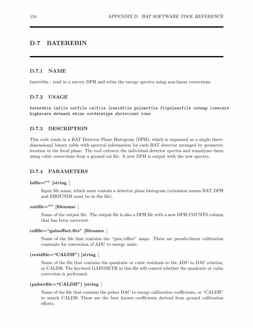
134 APPENDIX D. BAT SOFTWARE TOOL REFERENCE
D.7 BATEREBIN
D.7.1 NAME
baterebin - read in a survey DPH and rebin the energy spectra using non-linear corrections
D.7.2 USAGE
baterebin infile outfile calfile [residfile pulserfile fltpulserfile outmap lowecarehighecare detmask ebins outdatatype wholecount rows
D.7.3 DESCRIPTION
This code reads in a BAT Detector Plane Histogram (DPH), which is organized as a single three-dimensional binary table with spectral information for each BAT detector arranged by geometriclocation in the focal plane. The tool extracts the individual detector spectra and reanalyzes themusing cubic corrections from a ground cal file. A new DPH is output with the new spectra.
D.7.4 PARAMETERS
infile=”” [string ]
Input file name, which must contain a detector plane histogram (extension names BAT DPHand EBOUNDS must be in the file).
outfile=”” [filename ]
Name of the output file. The output file is also a DPH file with a new DPH COUNTS columnthat has been corrected.
calfile=“gainoffset.fits” [filename ]
Name of the file that contains the “gain/offset” maps. These are pseudo-linear calibrationconstants for conversion of ADU to energy units.
(residfile=“CALDB”) [string ]
Name of the file that contains the quadratic or cubic residuals to the ADU to DAC relation,or CALDB. The keyword GAINMETH in this file will control whether the quadratic or cubiccorrection is performed.
(pulserfile=“CALDB”) [string ]
Name of the file that contains the pulser DAC to energy calibration coefficients, or “CALDB”to search CALDB. These are the best known coefficients derived from ground calibrationefforts.
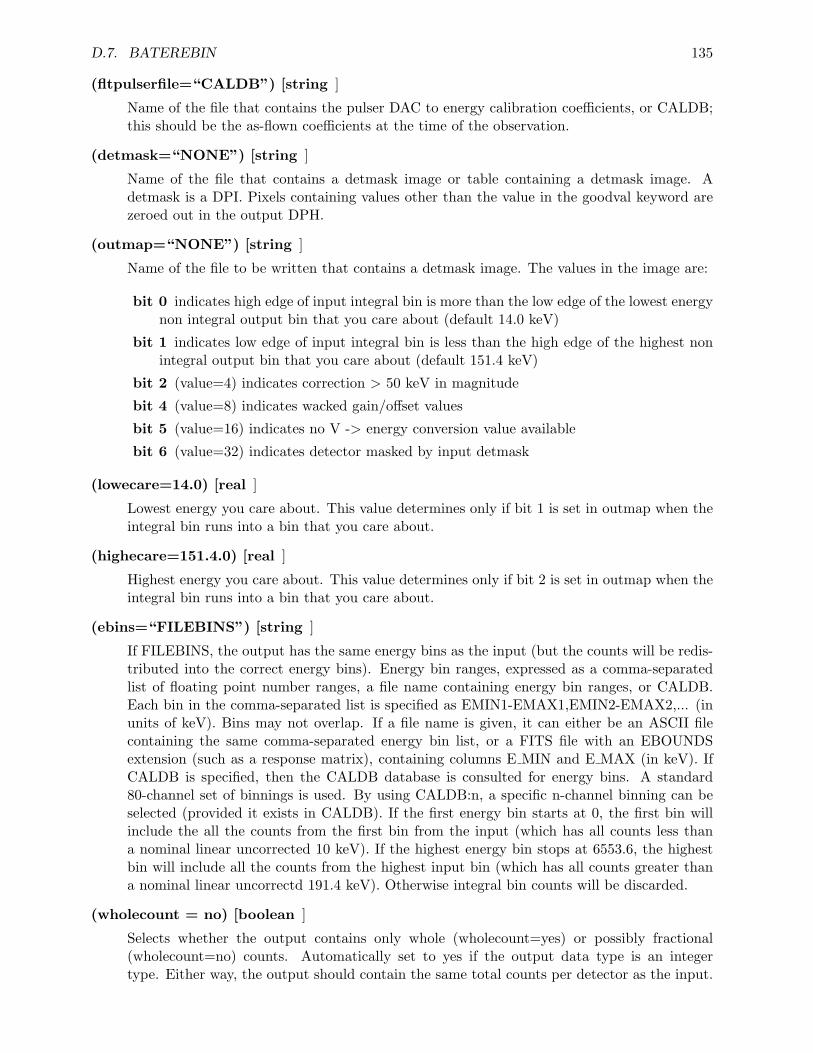
D.7. BATEREBIN 135
(fltpulserfile=“CALDB”) [string ]
Name of the file that contains the pulser DAC to energy calibration coefficients, or CALDB;this should be the as-flown coefficients at the time of the observation.
(detmask=“NONE”) [string ]
Name of the file that contains a detmask image or table containing a detmask image. Adetmask is a DPI. Pixels containing values other than the value in the goodval keyword arezeroed out in the output DPH.
(outmap=“NONE”) [string ]
Name of the file to be written that contains a detmask image. The values in the image are:
bit 0 indicates high edge of input integral bin is more than the low edge of the lowest energynon integral output bin that you care about (default 14.0 keV)
bit 1 indicates low edge of input integral bin is less than the high edge of the highest nonintegral output bin that you care about (default 151.4 keV)
bit 2 (value=4) indicates correction > 50 keV in magnitude
bit 4 (value=8) indicates wacked gain/offset values
bit 5 (value=16) indicates no V -> energy conversion value available
bit 6 (value=32) indicates detector masked by input detmask
(lowecare=14.0) [real ]
Lowest energy you care about. This value determines only if bit 1 is set in outmap when theintegral bin runs into a bin that you care about.
(highecare=151.4.0) [real ]
Highest energy you care about. This value determines only if bit 2 is set in outmap when theintegral bin runs into a bin that you care about.
(ebins=“FILEBINS”) [string ]
If FILEBINS, the output has the same energy bins as the input (but the counts will be redis-tributed into the correct energy bins). Energy bin ranges, expressed as a comma-separatedlist of floating point number ranges, a file name containing energy bin ranges, or CALDB.Each bin in the comma-separated list is specified as EMIN1-EMAX1,EMIN2-EMAX2,... (inunits of keV). Bins may not overlap. If a file name is given, it can either be an ASCII filecontaining the same comma-separated energy bin list, or a FITS file with an EBOUNDSextension (such as a response matrix), containing columns E MIN and E MAX (in keV). IfCALDB is specified, then the CALDB database is consulted for energy bins. A standard80-channel set of binnings is used. By using CALDB:n, a specific n-channel binning can beselected (provided it exists in CALDB). If the first energy bin starts at 0, the first bin willinclude the all the counts from the first bin from the input (which has all counts less thana nominal linear uncorrected 10 keV). If the highest energy bin stops at 6553.6, the highestbin will include all the counts from the highest input bin (which has all counts greater thana nominal linear uncorrectd 191.4 keV). Otherwise integral bin counts will be discarded.
(wholecount = no) [boolean ]
Selects whether the output contains only whole (wholecount=yes) or possibly fractional(wholecount=no) counts. Automatically set to yes if the output data type is an integertype. Either way, the output should contain the same total counts per detector as the input.
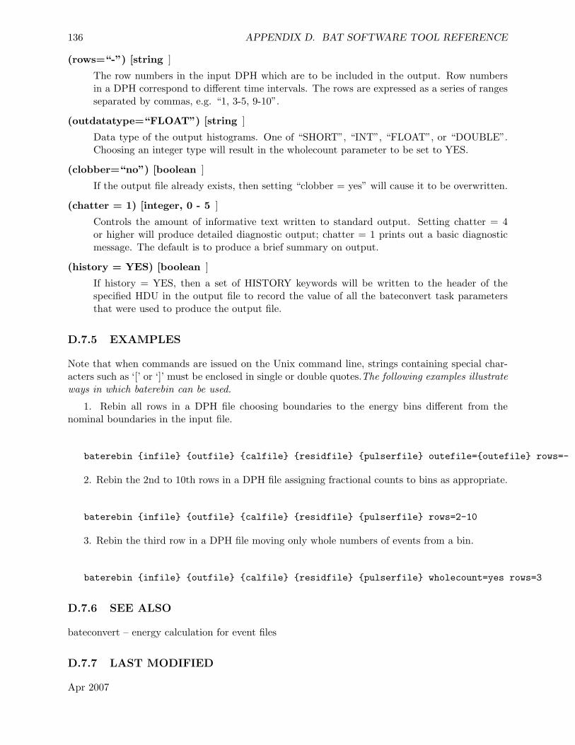
136 APPENDIX D. BAT SOFTWARE TOOL REFERENCE
(rows=“-”) [string ]
The row numbers in the input DPH which are to be included in the output. Row numbersin a DPH correspond to different time intervals. The rows are expressed as a series of rangesseparated by commas, e.g. “1, 3-5, 9-10”.
(outdatatype=“FLOAT”) [string ]
Data type of the output histograms. One of “SHORT”, “INT”, “FLOAT”, or “DOUBLE”.Choosing an integer type will result in the wholecount parameter to be set to YES.
(clobber=“no”) [boolean ]
If the output file already exists, then setting “clobber = yes” will cause it to be overwritten.
(chatter = 1) [integer, 0 - 5 ]
Controls the amount of informative text written to standard output. Setting chatter = 4or higher will produce detailed diagnostic output; chatter = 1 prints out a basic diagnosticmessage. The default is to produce a brief summary on output.
(history = YES) [boolean ]
If history = YES, then a set of HISTORY keywords will be written to the header of thespecified HDU in the output file to record the value of all the bateconvert task parametersthat were used to produce the output file.
D.7.5 EXAMPLES
Note that when commands are issued on the Unix command line, strings containing special char-acters such as ‘[’ or ‘]’ must be enclosed in single or double quotes.The following examples illustrateways in which baterebin can be used.
1. Rebin all rows in a DPH file choosing boundaries to the energy bins different from thenominal boundaries in the input file.
baterebin {infile} {outfile} {calfile} {residfile} {pulserfile} outefile={outefile} rows=-
2. Rebin the 2nd to 10th rows in a DPH file assigning fractional counts to bins as appropriate.
baterebin {infile} {outfile} {calfile} {residfile} {pulserfile} rows=2-10
3. Rebin the third row in a DPH file moving only whole numbers of events from a bin.
baterebin {infile} {outfile} {calfile} {residfile} {pulserfile} wholecount=yes rows=3
D.7.6 SEE ALSO
bateconvert – energy calculation for event files
D.7.7 LAST MODIFIED
Apr 2007
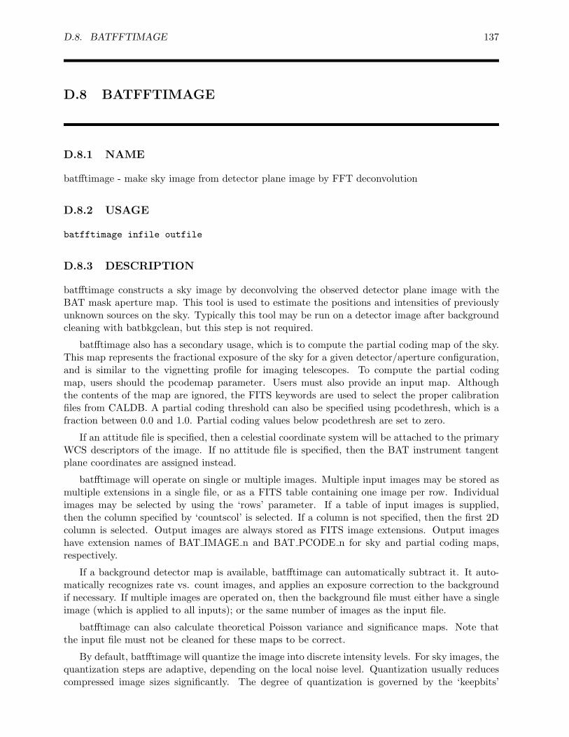
D.8. BATFFTIMAGE 137
D.8 BATFFTIMAGE
D.8.1 NAME
batfftimage - make sky image from detector plane image by FFT deconvolution
D.8.2 USAGE
batfftimage infile outfile
D.8.3 DESCRIPTION
batfftimage constructs a sky image by deconvolving the observed detector plane image with theBAT mask aperture map. This tool is used to estimate the positions and intensities of previouslyunknown sources on the sky. Typically this tool may be run on a detector image after backgroundcleaning with batbkgclean, but this step is not required.
batfftimage also has a secondary usage, which is to compute the partial coding map of the sky.This map represents the fractional exposure of the sky for a given detector/aperture configuration,and is similar to the vignetting profile for imaging telescopes. To compute the partial codingmap, users should the pcodemap parameter. Users must also provide an input map. Althoughthe contents of the map are ignored, the FITS keywords are used to select the proper calibrationfiles from CALDB. A partial coding threshold can also be specified using pcodethresh, which is afraction between 0.0 and 1.0. Partial coding values below pcodethresh are set to zero.
If an attitude file is specified, then a celestial coordinate system will be attached to the primaryWCS descriptors of the image. If no attitude file is specified, then the BAT instrument tangentplane coordinates are assigned instead.
batfftimage will operate on single or multiple images. Multiple input images may be stored asmultiple extensions in a single file, or as a FITS table containing one image per row. Individualimages may be selected by using the ‘rows’ parameter. If a table of input images is supplied,then the column specified by ‘countscol’ is selected. If a column is not specified, then the first 2Dcolumn is selected. Output images are always stored as FITS image extensions. Output imageshave extension names of BAT IMAGE n and BAT PCODE n for sky and partial coding maps,respectively.
If a background detector map is available, batfftimage can automatically subtract it. It auto-matically recognizes rate vs. count images, and applies an exposure correction to the backgroundif necessary. If multiple images are operated on, then the background file must either have a singleimage (which is applied to all inputs); or the same number of images as the input file.
batfftimage can also calculate theoretical Poisson variance and significance maps. Note thatthe input file must not be cleaned for these maps to be correct.
By default, batfftimage will quantize the image into discrete intensity levels. For sky images, thequantization steps are adaptive, depending on the local noise level. Quantization usually reducescompressed image sizes significantly. The degree of quantization is governed by the ‘keepbits’
138 APPENDIX D. BAT SOFTWARE TOOL REFERENCE
parameter, and quantization can be disabled. The default quantization (7 bits of noise) should bemore than enough to preserve all image features.
D.8.4 PARAMETERS
infile [filename ]
Input file name containing BAT detector plane image. If pcodemap is ‘YES’, then the contentsof the map are ignored, but the keywords from the map file are used to select the calibrationfiles from CALDB. Thus, using a detector enable map or a quality map is appropriate in thatcase. Avoid using the CFITSIO syntax to select image extensions; use the ‘rows’ parameterinstead.
outfile [filename ]
Output sky image or partial coding map file name.
attitude = “NONE” [string ]
Swift attitude file name. If NONE is given, then a celestial coordinate system cannot beassigned to the image.
(aperture = “CALDB:FLUX”)[filename ]
BAT aperture map file name, which contains the coded mask pattern and alignment pa-rameters. If the CALDB database is set up, then CALDB can also be specified. If severalaperture types are available in the CALDB, the user can specify CALDB:apertype. Validvalues of apertype are currently: FLUX or DETECTION, for apertures optimized for fluxreproducibility or detection sensitivity, respectively.
(detmask = “NONE”) [string ]
Name of a detector quality map file. This should be an image file with the same dimensionsas the focal plane map. A pixel value of 0 indicates the detector is enabled for imaging, anda non-zero value indicates disabled. A default value of NONE implies all detectors are on,except for the BAT detector gap regions.
(bkgfile = “NONE”) [string ]
Name of a file containing background image data to be subtracted from the input. A valueof NONE indicates no subtraction should be performed.
(bkgvarmap=“NONE”) [string ]
Optional output file name for the theoretical Poisson background fluctuation map. This mapwill be either the standard deviation map or the variance map depending on the value ofbkgvartype. NOTE: The input map must not be cleaned for the theoretical map to becomputed properly. A value of NONE indicates no fluctuation maps should be created. Avalue of APPEND indicates that each fluctuation map should be appended to the output filegiven by ‘outfile’.
(bkgvartype=“STDDEV”) [string ]
Type of output fluctuation map. Valid values are: STDDEV, for a standard deviation map;or VARIANCE, for a variance map.
D.8. BATFFTIMAGE 139
(signifmap=“NONE”) [string ]
Optional output file name for the significance map based on the theoretical Poisson variancemap (see ‘bkgvarmap’ for restrictions). A value of NONE indicates no significance mapsshould be created. A value of APPEND indicates that each significance map should beappended to the output file given by ‘outfile’.
(oversampx = 2) [integer ]
Oversampling factor of image in X direction. Finer sampling may allow peaks which straddlepixel boundaries to be detected, but of course will result in increased compute time and diskstorage.
(oversampy = 2) [integer ]
Oversampling factor of image in Y direction.
(maskoffx = 0.0) [real ]
Translational offset to apply to the mask along the BAT X coordinate from its nominal designposition.
(maskoffy = 0.0) [real ]
Translational offset to apply to the mask along the BAT Y coordinate from its nominal designposition.
(maskoffz = 0.0) [real ]
Translational offset to apply to the mask along the BAT Z coordinate from its nominal designposition.
(rebalance = YES) [boolean ]
If YES, then the detector and aperture maps will be adjusted so that their additive meansare zero. If NO, then, the maps will be used unadjusted. (NOTE: pcodemap implies rebal-ance=NO)
(pcodemap = “NO”) [string ]
Partial coding map output setting. The possible values are:
“NO” No partial coding maps are output (although they may be computed internally,depending on the required corrections).
“YES” Only the partial coding map is output.“APPEND ALL” Append each partial coding map to the output.“APPEND LAST” Append only the last partial coding map to the output.
• Note that if the spacecraft attitude changes between sequential input images, then the coor-dinate system attached to the partial coding map will also change. Use APPEND ALL inthis case. If the spacecraft attitude is known to be fixed (for example, if each image is takenat the same time, but in different energy bands), then APPEND LAST will append only onepartial coding map, and thus save space.
(pcodethresh = 0.01) [real ]
Minimum allowable partial coding value in the partial coding map. This is a fraction between0.0 (no partial coding) and 1.0 (fully coded). The default of 0.01 implies that at least 1%of the detectors must be illuminated. Values below the threshold will be set to zero in thepartial coding map.
140 APPENDIX D. BAT SOFTWARE TOOL REFERENCE
(bat z = 0) [real ]
For testing with a near-field source. The position of the source in centimeters along theBAT Z axis. A value of 0 indicates infinity.
(origin z = 0) [real ]
For ground testing with a near-field source. The position of the origin of coordinates (in cm),used for the angular measures attached to the output image.
(corrections = “default”) [string ]
Comma-separated list of corrections to apply to the image, or “none” if no corrections are tobe applied. The possible corrections are:
default Default corrections, which is shorthand for: ”autocollim,flatfield,maskwt,ndets,pcode”
autocollim Correct plate scale for autocollimation effect
flatfield Apply corrections for cosine and edge projection effects
maskwt Apply corrections for FFT technique
ndets Normalize by number of exposed detectors
pcode Apply partial coding corrections
(keepbits = “7”) [string ]
Integer number of bits of precision to keep in the output images. A value of ALL meanskeep all bits. A positive value indicates that ‘keepbits’ bits of precision should be preserved,and the other bits should be set to zero. Fewer kept bits means the output images are morecompressible, at the expense of lost precision. For partial coding maps and variance maps, astraight number of bits are kept (thus preserving the same relative precision across the map).For sky maps and significance maps, ‘keepbits’ prescribes the number ofnoise bits to keep;more bits may be kept if a pixel is significantly above the noise (thus preserving the samenoise quantization error across the map). NOTE: it must be possible to compute a variancemap in order for most ‘keepbits’ operations to work. (see ‘bkgvarmap’ for restrictions).
(handedness = “left”) [string ]
The handedness of the image. For an image where north is up, a left-handed image hasEast=left, and a right-handed image has East=right. “left” is conventional for astronomicalimages.
(rows = “-”) [string ]
An index list of images to operate on. This is a standard comma-separated list of row ranges,starting with image number 1. A range of “-” indicates all images should be processed.
(countscol = “INDEF”) [string ]
If the input image is a FITS table, the column to analyze. If countscol is INDEF, then thefirst 2 dimensional column to be found in the table is used.
(teldef = “CALDB”) [string ]
BAT instrument telescope description file, which defines instrument-to-spacecraft alignments.Must be specified in order to assign celestial coordinates to the output image. A value of“NONE” disables celestial coordinates. By default the teldef file located in the HEADASreference data area is used. If the CALDB database is set up, then CALDB can also bespecified.
D.8. BATFFTIMAGE 141
(time = 0) [real ]
Command line override for the image time. This MET time is used to interpolate the attitudefile. By default the image midpoint time is used (= (TSTART+TSTOP)/2).
(maskwtswgain = 0.03) [real ]
Mask weight technique software gain correction factor. When corrections=maskwt, the imageis divided by (1+maskwtswgain). This is correction is software algorithm dependent and notintended to be changed by the user.
(copyall = YES) [boolean ]
If set, then batfftimage will copy any extra HDUs to the output file. If not set, then onlythe sky images are written. Extra extensions are any HDUs that come after the imageextension(s).
(clobber = NO) [boolean ]
If the output file already exists, then setting “clobber = yes” will cause it to be overwritten.
(chatter = 2) [integer, 0 - 5 ]
Controls the amount of informative text written to standard output. Setting chatter = 1produces a basic summary of the task actions; chatter = 2 (default) additionally prints asummary of input parameters; chatter = 5 prints debugging information.
(history = YES) [boolean ]
If history = YES, then a set of HISTORY keywords will be written to the header of thespecified HDU in the output file to record the value of all the task parameters that were usedto produce the output file.
D.8.5 EXAMPLES
1. Reconstructs the sky image from the detector plane image focalplane.img. The aperture map,aperture.img, is in the current directory.
batfftimage focalplane.img skyimage.img
2. Make a partial coding map for the given detector configuration given in detmask.img. Theoutput file is the image pcodemap.img. If the detmask parameter were not given, then a defaultone would be used, which assumed that all detectors were enabled.
batfftimage NONE pcodemap.img detmask=detmask.img pcodemap=YES
D.8.6 REFERENCES
Fast Fourier Transform routines by T. Ooura, used with permission. http://momonga.t.u-tokyo.ac.jp/∼ooura/
D.8.7 SEE ALSO
batbkgclean, batcelldetect

142 APPENDIX D. BAT SOFTWARE TOOL REFERENCE
D.8.8 LAST MODIFIED
Apr 2007
D.9. BATGLOBALGTI 143
D.9 BATGLOBALGTI
D.9.1 NAME
batglobalgti - retrieve BAT global science analysis times
D.9.2 USAGE
batglobalgti infile outfile
D.9.3 DESCRIPTION
batglobalgti retrieves global good or bad times for BAT science analysis. The BAT CALDB has aGTI file which contains a listing of all known good and bad science analysis times, include a qualityindicator and a description of any issues. This GTI is meant to reflect any operational issues thataffected the BAT science data quality which are not easily extractable from the filter file or othertelemetry. The user is not excused from doing other routine quality filtering, for example for SAAor noisy detectors. Thus, this task is most useful for doing gross filtering of data at the observationlevel to remove times of known bad data.
The time intervals stored in the GTI file have QUALITY values assigned according to thefollowing scale:
0 No known issues; data OK
1 Something non-routine occurred, but it had no known impact;
2 Bad data, with some possible good data; user must proceed with extreme caution;
3 Bad data, with little to no good data.
The user can choose which quality level to accept with the ‘expr’ parameter. The default valueis 0 or 1.
The result is a standard GTI file that can be merged with other GTI files, or otherwise used totime filter time-ordered Swift data. This GTI file applies to the entire mission duration.
Please note: The time intervals in the output file are not necessarily “good.” That dependson the quality level chosen (i.e. if one chooses expr=”QUALITY >= 2” then only the bad timeintervals will be selected).
D.9.4 PARAMETERS
infile [filename ]
Global good/bad science time interval file. A value of “CALDB” is allowed (and in factrecommended), indicating to select data from the Calibration database.
144 APPENDIX D. BAT SOFTWARE TOOL REFERENCE
outfile [filename ]
Name of the output GTI file.
(expr = “QUALITY <= 1”) [string ]
Quality level selection filter. Any row filter expression is allowed, involving the columnsSTART, STOP and QUALITY. “Good” data will typically be chosen with ”QUALITY <=1“ and ”bad“ data will have ”QUALITY >= 2”.
(clobber = NO) [boolean ]
If the output file already exists, then setting “clobber = yes” will cause it to be overwritten.
(chatter = 2) [integer, 0 - 5 ]
Controls the amount of informative text written to standard output.
D.9.5 EXAMPLES
1. Create a “good” time interval file from CALDB.
batglobalgti CALDB good.gti
D.9.6 SEE ALSO
maketime, mgtime
D.9.7 LAST MODIFIED
Sep 2006
D.10. BATGRBPRODUCT 145
D.10 BATGRBPRODUCT
D.10.1 NAME
batgrbproduct - standard BAT GRB processing
D.10.2 USAGE
batgrbproduct indir outdir
D.10.3 DESCRIPTION
batgrbproduct performs standard processing for gamma-ray bursts detected by the Swift BATinstrument. It performs the following activities:
• generation of a master quality map
• generation of good time interval files
• extraction of events near the time of the GRB
• computing mask weights for all events for the GRB position
• finding an optimal time interval based on Bayesian blocks analysis
• generation of sky images
• generation of a partial coding map
• refinement of the BAT position (if possible)
• generation of energy spectra for different time intervals, including
– pre-slew
– during-slew
– post-slew
generation of detector response matrices
generation of light curves with different samplings
computation of counts fluences
creation of a summary report
creation of a detailed execution log file
146 APPENDIX D. BAT SOFTWARE TOOL REFERENCE
NOTE: the scripts batgrbproduct and bat-burst-advocate are identical. The first name hasbeen preserved for historical reasons, and the second name for consistency with the product scriptsof the UVOT and XRT.
By default it is assumed that the TDRSS position message is present. This message providesinformation about the position of the burst and the initial time interval of the burst. However, theuser can override these values using command line parameters. If the RA and Dec values are setto BLIND, then sky images are made, but no further analysis is done, and it is up to the user tosearch the image to find new sources.
PREREQUISITES - the user must have the standard FTOOLS (6.0.5 or later) installed andset up. Also, the CALDB must be installed and set up. It is assumed that the input directorystructure is the same as that produced by the Swift Data Center (SDC). The event by event datashould already be energy-calibrated by either the SDC or running bateconvert manually (i.e. thePI and ENERGY columns should be filled).
D.10.4 SUMMARY OUTPUTS
Upon finishing, the output directory contains a text file calledprocess.log. This file contains allthe commands executed and detailed output transcripts. Users can check this file to: (a) diagnoseproblems; and (b) to get ideas on how to use the software to make their own custom scienceproducts.
The output directory also contains report.txt, which is text file with a summary report givingbasic statistics and factual information about the trigger that was analyzed.
The task concludes by printing to the console a detailed inventory of files it created, includingthe name and a brief description for each file.
D.10.5 OUTPUT DIRECTORIES
The output files are arranged by type into several directories. The following list describes eachdirectory. Each file name contains code phrases which are also described.
outdir/lc Light curves. File names with “1chan” and “4chan” have 1 and 4 energy bins respec-tively. Time binnings can be 1 second (“1s”), 64 millisecond (“64ms”) and 4 millisecond(“4ms”). The light curves cover the full range of event data.
outdir/pha Spectra and response matrices. Spectra are computed for the total burst interval,the T50/T90 intervals, the peak flux interval (1 second), and also for the pre-slew, slew, andpost-slew intervals. Response matrices are computed for the pre-slew and post-slew intervals.
outdir/dpi Detector images. Detector images are made in the pre-burst, pre-slew and post-slewtime intervals. Pre-burst means an image created before any detectable emission. Imageswith 1 and 4 energy bins are created.
outdir/img Sky and partial coding images. Sky images are made in the same time intervals asdetector images, but only for the 1-channel images. Small “postage-stamp” images are alsocreated (suffix “.postimg”), centered on the burst position. Partial coding maps are made forthe pre-slew and post-slew intervals.
outdir/gti Duration information. Various good time interval files are generated. Files with “acs”are spacecraft-attitude related (“acs 10am”, “acs sett”, “acs slew” corresponding to the 10-arcmin, settled, and slewing flags, respectively). Files with “grb” select events near the GRB
D.10. BATGRBPRODUCT 147
(within 1500 seconds), including the pre-slew, slew and post-slew intervals. The “tdrss”file contains time intervals transcribed from the TDRSS position message. Files with “bb”are Bayesian blocks produced with the battblocks task on light curves with different timebinnings.
outdir/auxil Auxiliary information. The file with “qmap” is a detector quality map. The file with“output.cat” contains a revised position based on a fit to all pre-slew data. The “output.reg”file is a region file suitable for use within DS9 or FV. The “evaux” file is an auxiliary ray-tracing file.
outdir/events Event files. Intermediate event files are stored here. Since they are re-created eachtime the task is run, the files in this directory can be deleted if desired.
D.10.6 ERRORS
Most error conditions are reported on the console. Please note that not all bursts are the same,and the Swift spacecraft response is not the same. For example, there may not be a slew to theburst, in which case, there won’t be “slew” and “post-slew” spectra or images. Also, if the burstdoes not extend past the end of the slew (if there is one), there will not be a post-slew spectrum.The task will report these failures to produce spectra and images as errors, but they are benign.
For certain kinds of bursts – namely short hard bursts – the task is not always able to find thetime interval of the burst. In those cases, the user must manually determine the time interval ofthe burst and use the trigtime and trigstop keywords to the task.
D.10.7 PARAMETERS
indir [string ]
Input directory containing Swift data. This directory must have the standard Swift archivelayout. Files in the input directory will not be modified.
outdir [string ]
Output directory which will contain the processing results. The output files are organizedby file type: events, pha (spectra), lc (light curves), gti (good time intervals), auxil (mis-cellaneous). Also a summary report is created (report.txt), and a detailed processing log(process.log).
ra = “BAT” [string ]
RA of the source (degrees). A value of “BAT” or “XRT” means that the BAT or XRTTDRSS position should be used. A value of “BLIND” means to do the analysis blind, with-out concentrating on any one position in the field of view. When “BLIND”, then the trig-time/trigstop/backstrt/backstop parameters must be specified.
dec = “BAT” [string . ]
Declination of the source (degrees). See “ra”.
trigtime = 0.0 [real ]
Start time of the foreground interval containing the burst in mission elapsed time. A value of0 indicates to use the times from the TDRSS position message, and a non-zero value overridesthe TDRSS message.
148 APPENDIX D. BAT SOFTWARE TOOL REFERENCE
trigstop = 0.0 [real ]
Stop time of the foreground interval containing the burst in mission elapsed time. A value of0 indicates to use the times from the TDRSS position message, and a non-zero value overridesthe TDRSS message.
backstrt = 0.0 [real ]
Start time of the background interval before the burst in mission elapsed time. A value of 0indicates to use the times from the TDRSS position message, and a non-zero value overridesthe TDRSS message.
backstop = 0.0 [real ]
Stop time of the background interval before the burst in mission elapsed time. A value of 0indicates to use the times from the TDRSS position message, and a non-zero value overridesthe TDRSS message.
date obs = “INDEF” [string ]
User override of the DATE-OBS keyword in event files. This parameter is useful if the inputdata has an invalid date, like ‘2001-01-01’ or ‘TBD’. In that case, set date obs=‘YYYY-MM-DD’ where YYYY-MM-DD is the date of the observation. A value of “INDEF” indicatesthat the DATE-OBS keyword should not be changed (although it will still be checked forvalidity).
(tbkgsub = YES) [boolean ]
If set, then the task instructs battblocks to perform background subtraction during the “back-ground” intervals before and after the GRB before estimating the T50/T90 durations. If notset, then it is assumed that the light curves are already background subtracted (via maskweighting). Caveats: setting tbkgsub=YES may cause problems if the light curve doesn’thave a true quiescent background interval; setting tbkgsub=NO may cause problems if thelight curve is not fully background subtracted.
(pcodethresh = 0.0) [real ]
Minimum partial coding threshold. Set this value to a number greater than 0 in order toexclude noisy data when a GRB passes out of the BAT field of view. A value of 0.0 includesall data; A value of 1.0 includes only data when the source is in the (small) BAT fully codedfield of view.
(chatter = 1) [integer, 0 - 5 ]
Currently ignored.
(history = YES) [boolean ]
Currently ignored.
D.10.8 EXAMPLES
1. Run the BAT GRB product script on BAT trigger 154112 (GRB 050908). The BAT GRB dataare archived in a directory called 00154112000 (the “000” refers to segment number 0). batgrbprod-uct will perform a standard analysis and place the results in the directory 00154112000-results.
batgrbproduct 00154112000 00154112000-results

D.10. BATGRBPRODUCT 149
D.10.9 SEE ALSO
batmaskwtevt, batbinevt, batdetmask, battblocks, batfftimage, batcelldetect, batgrbproduct
D.10.10 LAST MODIFIED
Nov 2006
150 APPENDIX D. BAT SOFTWARE TOOL REFERENCE
D.11 BATHOTPIX
D.11.1 NAME
bathotpix - locate and mask out hot pixels in a BAT detector image
D.11.2 USAGE
bathotpix infile outfile
D.11.3 DESCRIPTION
bathotpix locates hot pixels in a BAT detector plane image. Hot pixels can be a source of noise insubsequent image processing steps, and so should usually be excised.
This tool uses a histogram-based approach to locate the hottest and coldest pixels in the image.Given a distribution of counts, the “centermost” portion is selected as being good (the “keepfract”amount). If keepfract is 0.98, then 98% of the detectors are selected as good. The selection windowis further enlarged by bands on either side using the guardfract and guardval parameters. Valuesoutside the selection window are considered to be “cold” (too low) or “hot” (too high).
The output of the tool is a quality map of the same dimensions as the detector image. Valuesstored in the map are determined by the keywords below, but typically a value of 0 indicates a goodpixel. This mask can be input into downstream image processing stages. The second extension,BADPIX, is a binary table containing a list of bad pixels.
Users can submit an existing detector mask using the detmask parameter. Pixels with badquality are ignored by bathotpix in computing the distribution and selection windows. By default,the input mask is logically AND’d with the result, so that the output is the cumulative record ofexcised pixels. By default, BAT detector gaps are also excised.
D.11.4 PARAMETERS
infile [filename ]
Input file name containing a detector plane image.
outfile [filename ]
Output detector mask image.
(detmask = “NONE”) [string ]
Input detector mask image. Pixels with bad quality are ignored in the bathotpix analysis.
(row = 1) [integer ]
Image number to process, where the first image is number 1. This applies both to files withmultiple image extensions (where ‘row’ selects the extension number) and to files with onebinary table extension (where ‘row’ selects the table row).
D.11. BATHOTPIX 151
(keepfract = 0.98) [real ]
Fraction of non-zero detectors to select as good, initially.
(guardfract = 0.25) [real ]
Fractional amount to enlarge initially selected detectors, relative to the median value. Avalue of 0.25 indicates an enlargement of 0.25 x the median on both sides of the distribution.
(guardval = 5.0) [real ]
Further amount to enlarge the selection window, this time in counts. This keyword is presentfor the case of an image with very small dynamic range, where guardfract may be too smallto be effective.
(applygaps = yes) [boolean ]
If yes, then positions of BAT detector gaps are excised.
(mergemask = yes) [boolean ]
If yes, then the input mask is merged with the result before writing to the output. If no, thenonly the pixels adjusted within this run of bathotpix are written.
(zerothresh = 20.0) [real ]
Threshold value. If the median is above zerothresh, then pixels with zero are considered tobe COLD. If the median is below zerothresh, i.e. the total number of counts is very low, thenpixels with zero are considered to be okay.
(goodval = 0) [integer ]
Value to be used in detector mask maps to indicate a good pixel.
(badval = 1) [integer ]
Value to be used in detector mask maps to indicate a bad pixel, such as a detector gap.
(hotval = 1) [integer ]
Value to be used in detector mask maps to indicate a hot pixel.
(coldval = 1) [integer ]
Value to be used in detector mask maps to indicate a cold pixel.
(clobber = NO) [boolean ]
If the output file already exists, then setting “clobber = yes” will cause it to be overwritten.
(chatter = 1) [integer, 0 - 5 ]
Controls the amount of informative text written to standard output. Setting chatter = 1produces a basic summary and image statistics; chatter = 2 (default) additionally prints asummary of input parameters; chatter = 3 prints detailed information on which hot and colddetectors; chatter = 5 prints debugging information.
(history = YES) [boolean ]
If history = YES, then a set of HISTORY keywords will be written to the header of thespecified HDU in the output file to record the value of all the task parameters that were usedto produce the output file.
152 APPENDIX D. BAT SOFTWARE TOOL REFERENCE
D.11.5 EXAMPLES
1. Locate hot pixels in a detector plane image
bathotpix image.dpi image.mask
2. Same as example 1, but an input mask is also supplied
bathotpix image.dpi image.mask detmask=apriori.mask
D.11.6 SEE ALSO
batgse2dpi
D.11.7 LAST MODIFIED
Aug 2006
D.12. BATID2XY 153
D.12 BATID2XY
D.12.1 NAME
batid2xy - read in the detector number (either block, dm, side, detector numbers or single detectorID) and output the x/y position in the BAT array –OR– input the x/y position in the BAT arrayand output the detector identification.
D.12.2 USAGE
batid2xy infile [block] [dm] [side] [det] [detid] [detx] [dety] [outfile]
D.12.3 DESCRIPTION
This code can either read in an input FITS file containing a list of detector identifications or x/ypositions, or it can read these values from the command line (with the input file given as NONE).
The program calls batidconvert to figure out the X (column) and Y (row) numbers associatedwith the particular detector or does the reverse transformation. The output is always the fullidentification of the detector by DETID Block DM SIDE DET X Y.
There are three basic modes of conversion, which are abbreviated BDSD, DETID and DETXY.The mode is selected either by including a “BATIDMOD” keyword in the input file, or by supplyingvalid ( > -1) values of the detid, detx or dety parameters.
BDSD: In this mode, the conversion goes from detector identification to BAT X and Y (lo-cation in the detector plane). The detector is identified by, respectively, block (0:15), detectormodule (0:7), side (0:1), detector (0:127). In the input file, these are supplied in columns named“BLOCK”,“DM”,“SIDE” and “DET.” The keyword “BATIDMOD” is set to “BDSD.” On thecommand line, these are supplied through the block, dm, side and det parameters. See examplebelow.
DETID: In this mode, the conversion goes from detector identification to BAT X and Y (locationin the detector plane). The detector is identified by detector ID, which is derived from the formula:detid = block*2048 + dm*256 + side*128 + detector. In the input file, this is supplied in a columnname “DETID.” The keyword “BATIDMOD” is set to “DETID.” On the command line, this issupplied by setting the detid parameter equal to the detector ID. See example below.
DETXY: In this mode, the conversion goes from BAT X and Y (location in the detector plane)to detector identificaiton. The detector location is given by BATX and BATY. In the input file,these are supplied in columns named “DETX” and “DETY.” The keyword “BATIDMOD” is setto “DETXY.” On the command line, these are supplied through the detx and dety parameters.See example below.
D.12.4 PARAMETERS
infile [filename ]
154 APPENDIX D. BAT SOFTWARE TOOL REFERENCE
Input file name. The input file must have an extension called “DETID” and columns com-mensurate with the “BATIDMOD” keyword (see general description above). If this keywordis missing, the code assumes that it is set to the value “BDSD.” See a description of how tocreate an input file under Example 1 below.
• If the input file is given as NONE, then the detector values to be converted are supplied onthe command line.
(block) [integer, 0 - 15 ]
Specify the block number. Ignored if a valid input file is specified or if any of the detid, detx,or dety parameters are greater than -1.
(dm) [integer, 0 - 7 ]
Specify the detector module number. Ignored if a valid input file is specified or if any of thedetid, detx, or dety parameters are greater than -1.
(side) [integer, 0 - 1 ]
Specify the detector module side. Ignored if a valid input file is specified or if any of thedetid, detx, or dety parameters are greater than -1. 0 is equivalent to A and 1 to B.
(det) [integer, 0 - 127 ]
Specify the detector number. Ignored if a valid input file is specified or if any of the detid,detx, or dety parameters are greater than -1.
(detid) [integer, -1 to 32767 ]
Specify the detector id (block*2048 + dm*256 + side*128 + detector). If a different iden-tification of detectors is desired, then this parameter should be set to -1. Ignored if a validinput file is specified.
(detx) [integer, -1 to 285 ]
Specify the detector X location in detector units, starting from 0. If a different identificationof detectors is desired, then this parameter should be set to -1. Ignored if a valid input fileis specified. If the value provided corresponds to a gap in the detector array, then the codereturns a TNULL value for each detector identification.
(dety) [integer, -1 to 1273 ]
Specify the detector Y location in detector units, starting from 0. If a different identificationof detectors is desired, then this parameter should be set to -1. Ignored if a valid input fileis specified. If the value provided corresponds to a gap in the detector array, then the codereturns a TNULL value for each detector identification.
(outfile) [filename ]
Output file name. It is not currently implemented to write the output to a FITS file.
(clobber = NO) [boolean ]
If the output file already exists, then setting “clobber = yes” will cause it to be overwritten.
(chatter = 1) [integer, 0 - 5 ]
Controls the amount of informative text written to standard output. Setting chatter = 5 willproduce detailed diagnostic output, otherwise this task normally does not write any output.
D.12. BATID2XY 155
(history = NO) [boolean ]
If history = YES, then a set of HISTORY keywords will be written to the header of thespecified HDU in the output file to record the value of all the ftcopy task parameters thatwere used to produce the output file.
D.12.5 EXAMPLES
Note that when commands are issued on the Unix command line, strings containing special char-acters such as ‘[’ or ‘]’ must be enclosed in single or double quotes.The following examples illustrateways in which batid2xy can be used.
1. With an input file (“BDSD” mode).
batid2xy infile=’detids.fits’-or- batid2xy detids.fits
An input file can be created from an ascii table containing the block, dm, side, and detectorvalues in columns 1-4, respectively. A template to create the proper column names can be foundin the batid2xy directory as the file bdsd mode.lis. A header template is bdsd mode.hdr.
If the data is in a file called data.lis, then the input file detids.fits is created using one of thefollowing commands. Both of these assume that the template files are in the current directory.
create_input.pl infile="data.lis" outfile="detids.fits"-or-
fcreate bdsd_mode.lis data.lis detids.fits extname="DETID"headfile=bdsd_mode.hdr clobber=yes
2. With no input file (“BDSD” mode).
batid2xy NONE 7 3 1 67
3. With an input file (“DETID” mode).
batid2xy infile=’detids.fits’-or- batid2xy detids.fits
An input file can be created from an ascii table containing the detector ID values in column 1.A template to create the proper column names can be found in the batid2xy directory as the filedetid mode.lis. A header template is detid mode.hdr.
If the data is in a file called data.lis, then the input file detids.fits is created using one of thefollowing commands. Both of these assume that the template files are in the current directory.
156 APPENDIX D. BAT SOFTWARE TOOL REFERENCE
create_input.pl infile="data.lis" outfile="detids.fits" batidmod="detid"-or-
fcreate detid_mode.lis data.lis detids.fits extname="DETID"headfile=detid_mode.hdr clobber=yes
4. With no input file (“DETID” mode).
batid2xy NONE detid=15299
5. With an input file (“DETXY” mode).
batid2xy infile=’detids.fits’-or- batid2xy detids.fits
An input file can be created from an ascii table containing the detector X and Y values incolumns 1 and 2, respectively. A template to create the proper column names can be found in thebatid2xy directory as the file detxy mode.lis. A header template is detxy mode.hdr.
If the data is in a file called data.lis, then the input file detids.fits is created using one of thefollowing commands. Both of these assume that the template files are in the current directory.
create_input.pl infile="data.lis" outfile="detids.fits" batidmod="detxy"-or-
fcreate detxy_mode.lis data.lis detids.fits extname="DETID"headfile=detxy_mode.hdr clobber=yes
6. With no input file (“DETXY” mode).
batid2xy NONE detx=259 dety=102
D.12.6 SEE ALSO
fcreate
D.12.7 LAST MODIFIED
Dec 2007
D.13. BATMASKTAGLC 157
D.13 BATMASKTAGLC
D.13.1 NAME
batmasktaglc - Compute background subtracted light curves from raw BAT mask tagged counts
D.13.2 USAGE
batmasktaglc infile quadfile maskwt outfile [detmask] [ebounds]
D.13.3 DESCRIPTION
batmasktaglc converts a raw “mask tagged” light curve, produced by the BAT flight software, intoa background subtracted mask weighted light curve. The BAT flight software by itself produces“unbalanced” mask weighted sums, which introduces a bias. This task must be used to remove thebias.
The three basic inputs to the task are the raw mask tagged light curve; the “quadrant rates”light curve; and the mask weight map used by the flight software to create the raw mask taggedlight curves.
Generally speaking, raw mask tagged light curves will be stored with file names like: swNNNNNNNNNNNbmtCCCCCCCC rw.lc.gz,where NNNNNNNN is the observation and segment numbers, andCCCCCCCC is the bat catalognumber for the source. A given observation may contain multiple mask tagged sources. TheBAT can produce mask tagged light curves for up to three sources simultaneously. In addition,the sources chosen for mask tagging may vary from pointing to pointing in the same observation.Gamma-ray burst mask tagged light curves will have a catalog number of the form, 0002CCCC,where CCCC matches the last four digits of the GRB trigger number in decimal.
The quadrant rates file is typically in the obsid/bat/rate directory, with a file name, swNNNNNNNNNNNbrtqd.lc.It contains the total rates in each quadrant of the instrument, in several energy bands.
A mask weight map is produced by the BAT every time the mask tagged sources change(typically every pointing), and describes the weighting each detector had in computing the masktagged sums. Typically, the maps should be attached to the raw mask tagged light curve file asfollow-on extensions. Thus, users should normally just set “maskwt=INFILE”. The extension nameof the weight map should be “MASK TAG WEIGHT”.
The tool basically backs out the light curve processing that was carried out in the flight code toderive a background subtracted light curve and appropriate statistical error bars. The output fileis a standard light curve file, containing TIME, RATE, ERROR and BACKGROUND columns,each entry of which is a four-dimensional vector, with one number for each of the energy rangesdescribed in the EBOUNDS extension.
158 APPENDIX D. BAT SOFTWARE TOOL REFERENCE
D.13.4 IMPORTANT NOTES
The mask tagged light curves are invalid during spacecraft slews. Mask tagged data during slewsshould be ignored.
The generation of the output file will fail if the file is too large to fit the available memory.
D.13.5 PARAMETERS
infile [filename ]
Name of the raw mask tagged rate file, as described above.
quadfile [filename ]
Name of the input quadrant rate file.
maskwt [string ]
Name of mask weight map file. Normally, users should set the value to “INFILE” or “FILE”,to indicate that the mask weight map is attached to the raw mask tagged light curve.
outfile [filename ]
Output light curve file name.
(detmask = “none”) [string ]
Optional input detector plane mask. This is used to exclude detectors that are disabledfrom contributing to the light curves and errors. This file should always be a flight codegenerated detector mask which represents only detectors actually turned off, rather than amask derived from ground processing. Typically, these files are found in files named likeobsid/bat/hk/swNNNNNNNNNNNbdecb.fits.
(ebounds = “INFILE”) The location of the EBOUNDS file describing the energy ranges inthe light curves. The default is to use an EBOUNDS extension that is part of the infile (use“INFILE” or “FILE”). One can also specify “CALDB” if the EBOUNDS extension is notpresent.
(corrections = “default”) [string ]
Comma-separated list of corrections to apply to the mask weighting, or “none” if no correc-tions are to be applied. Other possible correction types are: “flatfield” (basic flat fieldingcorrection accounting for both cosine-type and r-squared-type effects); “cosine” (cosine ef-fects of off-axis illumination only); “pcode” (partial coding effect only); “ndets” (correctionfor disabled detectors). The “default” correction is pcode,flatfield,ndets.
(detdiv = “YES”) [string ]
Do you want the rate to be per detector (detdiv=“YES”) or for the whole array (det-div=“NO”). The division is only applied if the corrections parameter includes “ndets”. Notethat if no detector mask is supplied, then the rate will be divided by the total number ofdetectors (32768).
(scale = 1.3) [real ]
The user is allowed to supply a scale factor to correct for any known errors in how the rawmask-tagged light curve is calculated. The scale factor is multiplicative and scales all outputcounts by the same factor. The default value of this parameter was determined empirically
D.13. BATMASKTAGLC 159
for the average case. The user can override the default with a more precisely determined scalefactor.
(clobber = NO) [boolean ]
If the output file already exists setting clobber=Yes causes the existing output file to beoverwritten.
(chatter = 1) [integer 0 - 5 ]
The chatter value controls the amount of output written to standard output. Setting chatter= 5 causes detailed diagnostic output to be written to standard output.
(history = YES) [boolean ]
If history = YES, then a set of HISTORY keywords will be written to the header of thespecified HDU in the output file to record the value of all the task parameters that were usedto produce the output file.
D.13.6 EXAMPLES
• Note that when commands are issued on the Unix command line, strings containing specialcharacters such as ‘[’ or ‘]’ must be enclosed in single or double quotes.
1. Generate a mask weighted light curve for GRB 050922B (trigger 156434).
batmasktaglc infile=sw00156434000bmt00026434_rw.lc.gz \quadfile=sw00156434000brtqd.lc.gz maskwt=FILE \outfile=grb050922b.lc ebounds=CALDB clobber=YES
Note that mask weighted data during slews should be ignored.
D.13.7 LAST MODIFIED
Nov 2006
160 APPENDIX D. BAT SOFTWARE TOOL REFERENCE
D.14 BATMASKWTEVT
D.14.1 NAME
batmaskwtevt - compute mask weights for an event file
D.14.2 USAGE
batmaskwtevt infile attitude ra dec
D.14.3 DESCRIPTION
batmaskwtevt applies mask weighting, for a particular source position, to an event file. This is thefirst step to creating a light curve or spectrum for a source from event data.
By default, the coordinates are right ascension and declination. Users must also provide theinstrument aperture and teldef files (or use CALDB). Instrument coordinates can also be used, asdescribed in ADVANCED COORDINATE SYSTEMS below.
D.14.4 ADVANCED COORDINATE SYSTEMS
Users may specify a source position using a coordinate system other than sky position. Dependingon the value of the coord type parameter, the user may give the cartesian or angular positionof the source in instrument coordinates. When coord type is changed from “sky” to any of theother coordinate systems, then the meaning of the ra and dec parameters changes according to thefollowing table:
COORD_TYPE RA parameter DEC parameter Units------------------------------------------------------------sky Right Ascension Declination degtanxy Tan(theta_x) Tan(theta_y) nonecartesian BAT_X position BAT_Y position cmunit BAT_X unit vector BAT_Y unit vector nonefswlonlat Phi (flt. software) Theta deggrmclonlat Longitude (GRMC) Latitude deg
The coordinate types “fswlonlat” and “grmclonlat” are coordinate systems used in the flightsoftware and instrument simulators. The coordinate type “tanxy” gives the tangent-plane anglesof the source. Where necessary the source distance and/or BAT Z position must also be provided(in centimeters).
D.14. BATMASKWTEVT 161
D.14.5 DISTORTION CORRECTION
Batmaskwtevt can correct for systematic non-linear centroid shifts in the BAT imaging system.It is assumed that the input position (either celestial or instrumental) is in “true” undistortedcoordinates. All distortion corrections occur internally within the task. The distortion correctionoccurs if the ‘distfile’ parameter points to a correction map.
D.14.6 PARAMETERS
infile [filename ]
Input event file name. This file must contain BAT events, and have at least the columnsTIME, MASK WEIGHT, DETX and DETY. The MASK WEIGHT column is overwrittenby this tool, so the file must be writeable.
attitude [string ]
File name of Swift attitude history, or NONE if none is used.
ra [real ]
Right ascension of source in decimal degrees, or other source position coordinate, dependingon coord type.
dec [real ]
Declination of source in decimal degrees, or other source position coordinate, depending oncoord type.
(aperture = “CALDB”)[filename ]
BAT aperture map file name, which contains the coded mask pattern and alignment pa-rameters. If the CALDB database is set up, then CALDB can also be specified. If severalaperture types are available in the CALDB, the user can specify CALDB:apertype. Validvalues of apertype are currently: FLUX or DETECTION, for apertures optimized for fluxreproducibility or detection sensitivity, respectively.
(coord type = “sky”) [string ]
Method of specifying the source coordinates. It should be one of: “sky”; “tanxy” (coordinatesexpressed in tangent-plane coordinates); “cartesian” (source at cartesian position in BATcoordinates); “unit” (unit vector direction in BAT coordinates); “fswlonlat” (flight softwarephi and theta); “grmclonlat” (source at simulator longitude and latitude). All coordinatetypes but the first are specified in the instrument coordinate system.
(rebalance = YES) [boolean ]
If YES, then the mask weight map will be adjusted so that its additive mean is zero. If NO,then, the map will be written unadjusted.
(corrections = “default”) [string ]
Comma-separated list of corrections to apply to the mask weighting, or “none” if no correc-tions are to be applied. The possible corrections are:
default Default corrections, which is shorthand for: “flatfield,ndets,pcode,maskwt”
flatfield Apply corrections for cosine and edge projection effects
162 APPENDIX D. BAT SOFTWARE TOOL REFERENCE
maskwt Apply corrections for mask weighting technique
pcode Apply partial coding corrections
ndets Normalize by number of exposed detectors
subpixelate Use slower but potentially higher fidelity algorithm
forward Reserved for clean procedure
unbalanced Reserved for clean procedure
nearfield Near field corrections for ground calibration analysis only
• The “pcode” and “ndets” corrections require the user to supply the detmaskkeyword.
(pcodethresh = 0.00) [real ]
Minimum allowable partial coding value allowed for the source position. This is a fractionbetween 0.0 (no partial coding) and 1.0 (fully coded). For example, a value of 0.01 impliesthat at least 1% of the detectors must be illuminated. Mask weights for events whose partialcoding is below the threshold will be set to zero.
(detmask = “NONE”) [string ]
Name of a detector quality map file. This should be an image file with the same dimensionsas the detector plane map. A pixel value of 0 indicates the detector is enabled, and a non-zerovalue indicates disabled. A default value of NONE implies all detectors are on, except for theBAT detector gap regions. This map is only used for computing the fraction of illuminatedpixels. The output mask weight map contains a value for all detectors in the array, regardlessof detmask.
(auxfile = “NONE”) [string ]
Specifies an auxiliary output file which describes the position of the source in the BATfield of view as a function of time, including various ray tracing diagnostics. The columnsare TIME (MET in seconds); BAT X/Y/ZOBJ (source position in instrument coordinatesin cm); IMX/Y (source tangent plane coordinates); PCODEFR (partial coding fraction);NGOODPIX (number of enabled detectors); MSKWTSQF (normalization parameter). Onerow is created for each ray tracing operation performed. This file is required for responsematrix generation during slews.
(filtexpr = ”(EVENT FLAGS == 0) —— (EVENT FLAGS == 16)”) [string ]
Event filtering expression to be applied to the data. Any column filtering expression usingthe columns or keywords in the event file is valid (see the help for the “colfilter” task formore information). Events that fail the expression will have their mask weight set to zero.The default expression rejects calibration and multi-hit events, which are never due to cosmicsources. NOTE: users should not use spatial filters which exclude certain detectors, sincebatmaskwtevt will be unable to properly normalize the weights. For spatial filtering, use adetmask.
(bat z = 0) [real ]
Position of the source in BAT Z coordinates, if coord type is “cartesian” (in units of cm).
(maskwtcol = “MASK WEIGHT”) [string ]
Name of mask weight column.
D.14. BATMASKWTEVT 163
(distance = 1.0e7) [real ]
Default bat z position if bat z is zero (centimeters).
(maskoffx = 0.0) [real ]
Translational offset to apply to the mask along the BAT X coordinate from its nominal designposition.
(maskoffy = 0.0) [real ]
Translational offset to apply to the mask along the BAT Y coordinate from its nominal designposition.
(maskoffz = 0.0) [real ]
Translational offset to apply to the mask along the BAT Z coordinate from its nominal designposition.
(maskthickness = INDEF) [string ]
Thickness of the lead mask tiles in centimeters. Normally this will be set to INDEF, whichreads the mask thickness from the aperture file. A thickness of 0 cm is permitted.
(distfile=CALDB) [string ]
The ‘distfile’ parameter should point to a FITS file containing an MxNx2 image (or CALDBto use the default instrument correction in the calibration database). The two planes of theimage are the non-linear distortion of the BAT “plate scale” as a function of position in thesky image. The values are offsets in tangent plane coordinates (IMX,IMY), and thereforeunitless. The first plane of the image cube is the IMX offset, and the second plane is theIMY offset. The sense of the offset is (TRUE-APPARENT), i.e. for a measured position intangent plane coordinates, the offset values should be *added* to arrive at the true positionin tangent plane coordinates. The images are low-resolution versions of the BAT field of viewin instrumental sky coordinates, and are meant to be interpolated to the desired sampling.The WCS keywords must specify the image coordinate systems.
(buffersize = 32768) [integer ]
Size of internal event buffer for processing.
(subpixsize = 0.02) [real ]
Size of detector subpixels used in computing mask weighting, in centimeters. Can be no largerthan 0.02 cm.
(teldef = “CALDB”) [string ]
BAT instrument telescope description file, which defines instrument-to-spacecraft alignments.Must be specified when celestial coordinates are provided. If the CALDB database is set up,then CALDB can also be specified.
(origin z = 0) [real ]
For ground testing with a near-field source. The position of the origin of coordinates (in cm),to which the source position is referred.
(maskwtswgain = 0.04) [real ]
Mask weight technique software gain correction factor. When corrections=maskwt, theweights are divided by (1+maskwtswgain). This is correction is software algorithm dependentand not intended to be changed by the user.
164 APPENDIX D. BAT SOFTWARE TOOL REFERENCE
(chatter = 2) [integer, 0 - 5 ]
Controls the amount of informative text written to standard output. Setting chatter = 1produces a basic summary of the task actions; chatter = 2 (default) additionally prints asummary of input parameters; chatter = 5 prints debugging information.
(history = YES) [boolean ]
If history = YES, then a set of HISTORY keywords will be written to the header of thespecified HDU in the output file to record the value of all the task parameters that were usedto produce the output file.
D.14.7 EXAMPLES
1. Computes the mask weights for a source at (RA,DEC) = (257.5500,-28.118) degrees. The eventfile sw00000001000bnone028.unf has its MASK WEIGHT column overwritten.
batmaskwtevt sw00000001000bnone028.unf attitude.dat 257.5500 -28.118
2. Computes mask weights for a source which is fixed in detector coordinates. The the tangent-plane coordinates are provided (tan(theta x) and tan(theta y)), with the source at a distance of107cm = 100 km. Because no attitude file is needed, NONE is specified.
batmaskwtevt sw00000001000bnone028.unf NONE 0.348 0.112coord_type=tanxy distance=1e7
3. Computes mask weights for a source which is fixed in detector coordinates. The X and Ycomponents of the unit vector are given; the Z unit vector is computed implicitly by batmaskwtevt,so that the full unit vector is (0.348, 0.112, 0.931). The source is placed at a distance of 107 cm =100 km.
batmaskwtevt sw00000001000bnone028.unf NONE 0.348 0.112coord_type=unit distance=1e7
D.14.8 SEE ALSO
batmaskwtimg, colfilter
D.14.9 LAST MODIFIED
Sep 2006
D.15. BATMASKWTIMG 165
D.15 BATMASKWTIMG
D.15.1 NAME
batmaskwtimg - compute mask weights for the entire detector BAT plane
D.15.2 USAGE
batmaskwtimg outfile attitude ra dec
D.15.3 DESCRIPTION
batmaskwtimg constructs a mask weighting map, for a particular source position, for the entireBAT detector plane. This is the first step to computing a flux or spectrum for a source from surveytype or image type data. The output is an image of the detector plane with one mask weight foreach detector.
Users can also compute a “forward” ray tracing map, which gives the expected counts in eachdetector based on a unit intensity source, accounting for various geometric optics effects. Usersshould use ”corrections=forward,unbalanced,flatfield“ and ”rebalance=no” in order to simulatesuch a map.
Users can also request analysis for a batch of sources in a catalog, using the ‘incatalog’ pa-rameter. The catalog must provide at least the source position (and optionally the name of thesource and an identifying number). By default, the output will contain multiple extensions, onefor each source. However, individual catalog maps can be combined into one map with the comb-meth parameter. NOTE: If the input catalog is empty, then no output catalog will be created. If‘clobber=yes’ is set and the input catalog is empty, then any pre-existing output file will be erased.
The actual output map type is controlled by the ‘outtype’ parameter. By default it isWEIGHTS, indicating to output the ray traced mask weights. If outtype=ZERO or out-type=NONZERO is chosen, then a “footprint” mask is made instead, which shows which partsof the aperture (or non-aperture) illuminates the array, regardless of the aperture pattern. Thismay be especially useful in combination with combmeth=“MIN” or “MAX”, to mask out portionsof the array illuminated by particular sources.
By default, the coordinates are right ascension and declination. Users must also provide theinstrument aperture and teldef files (or use CALDB). Instrument coordinates can also be used, asdescribed in ADVANCED COORDINATE SYSTEMS below.
D.15.4 ADVANCED COORDINATE SYSTEMS
Users may specify a source position using a coordinate system other than sky position. Dependingon the value of the coord type parameter, the user may give the cartesian or angular positionof the source in instrument coordinates. When coord type is changed from “sky” to any of the
166 APPENDIX D. BAT SOFTWARE TOOL REFERENCE
other coordinate systems, then the meaning of the ra and dec parameters changes according to thefollowing table:
COORD_TYPE RA parameter DEC parameter Units------------------------------------------------------------sky Right Ascension Declination degtanxy Tan(theta_x) Tan(theta_y) nonecartesian BAT_X position BAT_Y position cmunit BAT_X unit vector BAT_Y unit vector nonefswlonlat Phi (flt. software) Theta deggrmclonlat Longitude (GRMC) Latitude deg
The coordinate types “fswlonlat” and “grmclonlat” are coordinate systems used in the flightsoftware and instrument simulators. The coordinate type “tanxy” gives the tangent-plane anglesof the source. Where necessary the source distance and/or BAT Z position must also be provided(in centimeters).
D.15.5 DISTORTION CORRECTION
Batmaskwtevt can correct for systematic non-linear centroid shifts in the BAT imaging system.It is assumed that the input position (either celestial or instrumental) is in “true” undistortedcoordinates. All distortion corrections occur internally within the task. The distortion correctionoccurs if the ‘distfile’ parameter points to a correction map.
D.15.6 PARAMETERS
outfile [filename ]
Output image file name. The mask weight map will be written to the primary extension ofthis file.
attitude [string ]
File name of Swift attitude history, or NONE if none is used.
ra [real ]
Right ascension of source in decimal degrees, or other source position coordinate, dependingon coord type. This value is ignored if incatalog is specified.
dec [real ]
Declination of source in decimal degrees, or other source position coordinate, depending oncoord type. This value is ignored if incatalog is specified.
(infile = “NONE”) [string ]
The name of an input file containing valid Swift/BAT time and instrument keywords. Forexample, an existing detector plane image. The time and instrument keywords are used toselect the proper CALDB files, and also to determine the TSTART/TSTOP time for theoutput file. The keywords in infile are also cloned to the output file. If given, the ‘time’parameter overrides TSTART/TSTOP in infile. By default the midpoint time is used tocompute the spacecraft attitude.
D.15. BATMASKWTIMG 167
(aperture = “CALDB”)[filename ]
BAT aperture map file name, which contains the coded mask pattern and alignment pa-rameters. If the CALDB database is set up, then CALDB can also be specified. If severalaperture types are available in the CALDB, the user can specify CALDB:apertype. Validvalues of apertype are currently: FLUX, DETECTION, or MASK EDGES; for aperturesoptimized for flux reproducibility, detection sensitivity, or for the shadow of the edge of themask, respectively.
(coord type = “sky”) [string ]
Method of specifying the source coordinates. It should be one of: “sky”; “tanxy” (coordinatesexpressed in tangent-plane coordinates); “cartesian” (source at cartesian position in BATcoordinates); “unit” (unit vector direction in BAT coordinates); “fswlonlat” (flight softwarephi and theta); “grmclonlat” (source at simulator longitude and latitude). All coordinatetypes but the first are specified in the instrument coordinate system.
(time = 0) [real ]
Time associated with the mask weighted image. When coordinates are used, it is also possiblefor the attitude to change as a function of time. Specify the mission elapsed time of interestwith this parameter. A value of 0 (the default) indicates to use the first row of the attitudefile, or the time in ‘infile’ if it is present. Ignored for non-sky coordinate systems.
(rebalance = YES) [boolean ]
If YES, then the mask weight map will be adjusted so that its additive mean is zero. If NO,then, the map will be written unadjusted.
(bat z = 0) [real ]
Position of the source in BAT Z coordinates, if coord type is “cartesian” (in units of cm).
(incatalog = “NONE”) [string ]
Input source catalog containing source positions. The catalog should contain one row persource. A value of NONE indicates that the source coordinates should be taken from thecommand line.
(racol = “RA OBJ”) [string ]
Column name of the first coordinate value in the input catalog, typically right ascension.
(deccol = “DEC OBJ”) [string ]
Column name of the second coordinate value in the input catalog, typically declination.
(namecol = “NAME”) [string ]
Column name of the source name in the input catalog. This value is written to the outputkeyword named ‘OBJECT’. If NONE is specified, then this column is ignored.
(catnumcol = “CATNUM”) [string ]
Column name of the source catalog number in the input catalog. This value is written to theoutput keyword named ‘CATNUM’. If NONE is specified, then this column is ignored.
(outtype = “WEIGHTS”) [string ]
Type of output map (one of WEIGHTS, ZERO or NONZERO). For ZERO, the test (weight== 0) is performed on each pixel; for NONZERO, the test (weight != 0) is performed.(1=true; 0=false).
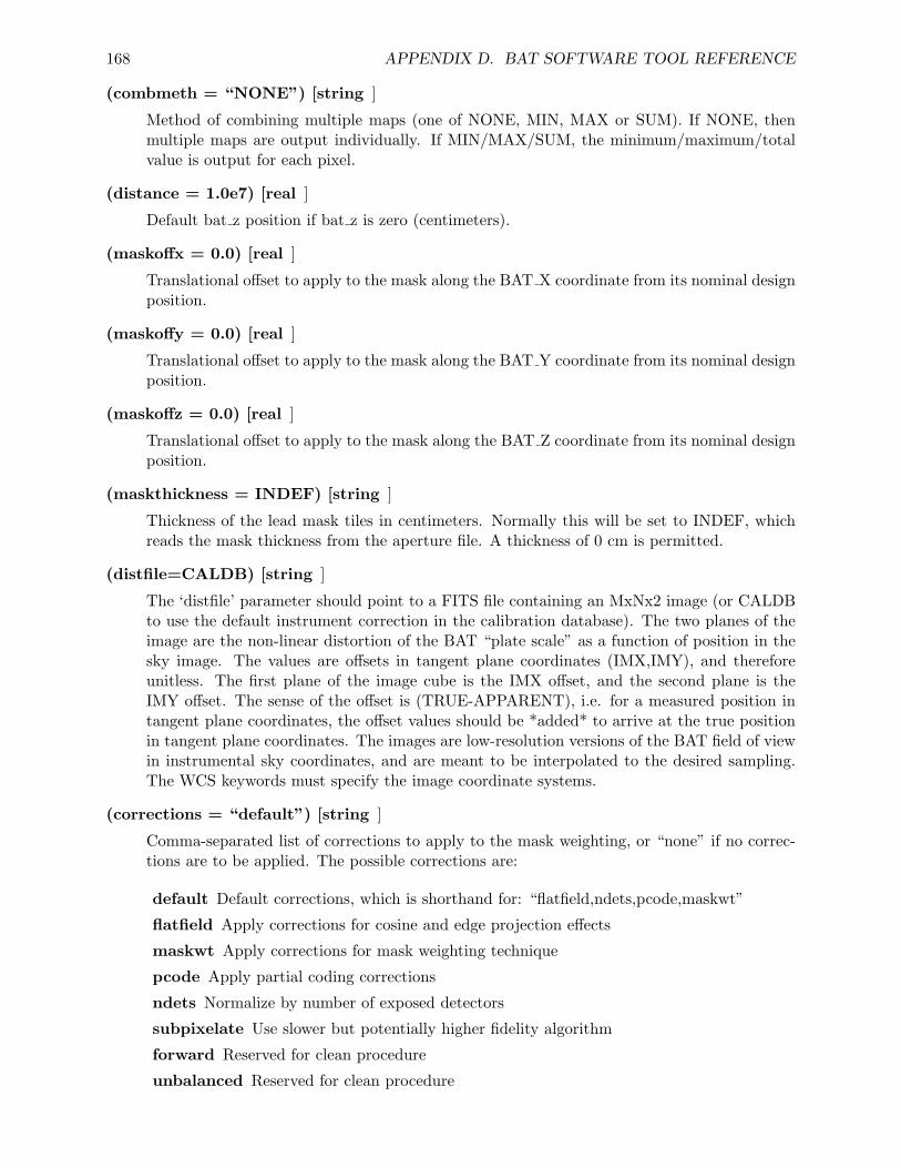
168 APPENDIX D. BAT SOFTWARE TOOL REFERENCE
(combmeth = “NONE”) [string ]
Method of combining multiple maps (one of NONE, MIN, MAX or SUM). If NONE, thenmultiple maps are output individually. If MIN/MAX/SUM, the minimum/maximum/totalvalue is output for each pixel.
(distance = 1.0e7) [real ]
Default bat z position if bat z is zero (centimeters).
(maskoffx = 0.0) [real ]
Translational offset to apply to the mask along the BAT X coordinate from its nominal designposition.
(maskoffy = 0.0) [real ]
Translational offset to apply to the mask along the BAT Y coordinate from its nominal designposition.
(maskoffz = 0.0) [real ]
Translational offset to apply to the mask along the BAT Z coordinate from its nominal designposition.
(maskthickness = INDEF) [string ]
Thickness of the lead mask tiles in centimeters. Normally this will be set to INDEF, whichreads the mask thickness from the aperture file. A thickness of 0 cm is permitted.
(distfile=CALDB) [string ]
The ‘distfile’ parameter should point to a FITS file containing an MxNx2 image (or CALDBto use the default instrument correction in the calibration database). The two planes of theimage are the non-linear distortion of the BAT “plate scale” as a function of position in thesky image. The values are offsets in tangent plane coordinates (IMX,IMY), and thereforeunitless. The first plane of the image cube is the IMX offset, and the second plane is theIMY offset. The sense of the offset is (TRUE-APPARENT), i.e. for a measured position intangent plane coordinates, the offset values should be *added* to arrive at the true positionin tangent plane coordinates. The images are low-resolution versions of the BAT field of viewin instrumental sky coordinates, and are meant to be interpolated to the desired sampling.The WCS keywords must specify the image coordinate systems.
(corrections = “default”) [string ]
Comma-separated list of corrections to apply to the mask weighting, or “none” if no correc-tions are to be applied. The possible corrections are:
default Default corrections, which is shorthand for: “flatfield,ndets,pcode,maskwt”
flatfield Apply corrections for cosine and edge projection effects
maskwt Apply corrections for mask weighting technique
pcode Apply partial coding corrections
ndets Normalize by number of exposed detectors
subpixelate Use slower but potentially higher fidelity algorithm
forward Reserved for clean procedure
unbalanced Reserved for clean procedure
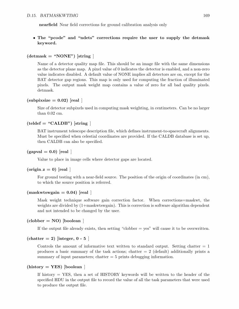
D.15. BATMASKWTIMG 169
nearfield Near field corrections for ground calibration analysis only
• The “pcode” and “ndets” corrections require the user to supply the detmaskkeyword.
(detmask = “NONE”) [string ]
Name of a detector quality map file. This should be an image file with the same dimensionsas the detector plane map. A pixel value of 0 indicates the detector is enabled, and a non-zerovalue indicates disabled. A default value of NONE implies all detectors are on, except for theBAT detector gap regions. This map is only used for computing the fraction of illuminatedpixels. The output mask weight map contains a value of zero for all bad quality pixels.detmask.
(subpixsize = 0.02) [real ]
Size of detector subpixels used in computing mask weighting, in centimeters. Can be no largerthan 0.02 cm.
(teldef = “CALDB”) [string ]
BAT instrument telescope description file, which defines instrument-to-spacecraft alignments.Must be specified when celestial coordinates are provided. If the CALDB database is set up,then CALDB can also be specified.
(gapval = 0.0) [real ]
Value to place in image cells where detector gaps are located.
(origin z = 0) [real ]
For ground testing with a near-field source. The position of the origin of coordinates (in cm),to which the source position is referred.
(maskwtswgain = 0.04) [real ]
Mask weight technique software gain correction factor. When corrections=maskwt, theweights are divided by (1+maskwtswgain). This is correction is software algorithm dependentand not intended to be changed by the user.
(clobber = NO) [boolean ]
If the output file already exists, then setting “clobber = yes” will cause it to be overwritten.
(chatter = 2) [integer, 0 - 5 ]
Controls the amount of informative text written to standard output. Setting chatter = 1produces a basic summary of the task actions; chatter = 2 (default) additionally prints asummary of input parameters; chatter = 5 prints debugging information.
(history = YES) [boolean ]
If history = YES, then a set of HISTORY keywords will be written to the header of thespecified HDU in the output file to record the value of all the task parameters that were usedto produce the output file.
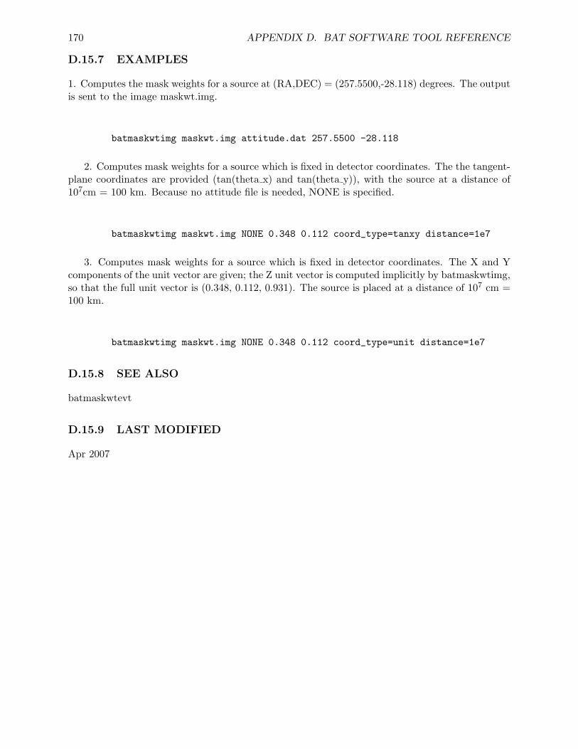
170 APPENDIX D. BAT SOFTWARE TOOL REFERENCE
D.15.7 EXAMPLES
1. Computes the mask weights for a source at (RA,DEC) = (257.5500,-28.118) degrees. The outputis sent to the image maskwt.img.
batmaskwtimg maskwt.img attitude.dat 257.5500 -28.118
2. Computes mask weights for a source which is fixed in detector coordinates. The the tangent-plane coordinates are provided (tan(theta x) and tan(theta y)), with the source at a distance of107cm = 100 km. Because no attitude file is needed, NONE is specified.
batmaskwtimg maskwt.img NONE 0.348 0.112 coord_type=tanxy distance=1e7
3. Computes mask weights for a source which is fixed in detector coordinates. The X and Ycomponents of the unit vector are given; the Z unit vector is computed implicitly by batmaskwtimg,so that the full unit vector is (0.348, 0.112, 0.931). The source is placed at a distance of 107 cm =100 km.
batmaskwtimg maskwt.img NONE 0.348 0.112 coord_type=unit distance=1e7
D.15.8 SEE ALSO
batmaskwtevt
D.15.9 LAST MODIFIED
Apr 2007
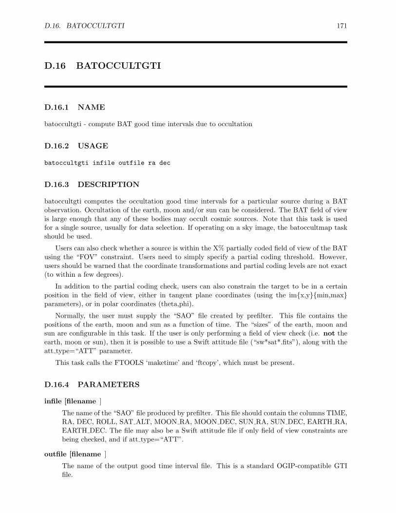
D.16. BATOCCULTGTI 171
D.16 BATOCCULTGTI
D.16.1 NAME
batoccultgti - compute BAT good time intervals due to occultation
D.16.2 USAGE
batoccultgti infile outfile ra dec
D.16.3 DESCRIPTION
batoccultgti computes the occultation good time intervals for a particular source during a BATobservation. Occultation of the earth, moon and/or sun can be considered. The BAT field of viewis large enough that any of these bodies may occult cosmic sources. Note that this task is usedfor a single source, usually for data selection. If operating on a sky image, the batoccultmap taskshould be used.
Users can also check whether a source is within the X% partially coded field of view of the BATusing the “FOV” constraint. Users need to simply specify a partial coding threshold. However,users should be warned that the coordinate transformations and partial coding levels are not exact(to within a few degrees).
In addition to the partial coding check, users can also constrain the target to be in a certainposition in the field of view, either in tangent plane coordinates (using the im{x,y}{min,max}parameters), or in polar coordinates (theta,phi).
Normally, the user must supply the “SAO” file created by prefilter. This file contains thepositions of the earth, moon and sun as a function of time. The “sizes” of the earth, moon andsun are configurable in this task. If the user is only performing a field of view check (i.e. not theearth, moon or sun), then it is possible to use a Swift attitude file (“sw*sat*.fits”), along with theatt type=“ATT” parameter.
This task calls the FTOOLS ‘maketime’ and ‘ftcopy’, which must be present.
D.16.4 PARAMETERS
infile [filename ]
The name of the “SAO” file produced by prefilter. This file should contain the columns TIME,RA, DEC, ROLL, SAT ALT, MOON RA, MOON DEC, SUN RA, SUN DEC, EARTH RA,EARTH DEC. The file may also be a Swift attitude file if only field of view constraints arebeing checked, and if att type=“ATT”.
outfile [filename ]
The name of the output good time interval file. This is a standard OGIP-compatible GTIfile.
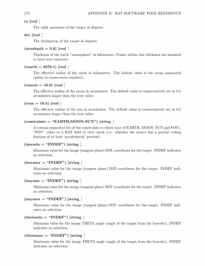
172 APPENDIX D. BAT SOFTWARE TOOL REFERENCE
ra [real ]
The right ascension of the target in degrees.
dec [real ]
The declination of the target in degrees.
(atmdepth = 5.0) [real ]
Thickness of the earth “atmosphere” in kilometers. Points within this thickness are assumedto have zero exposure.
(rearth = 6378.1) [real ]
The effective radius of the earth in kilometers. The default value is the mean equatorialradius (a conservative number).
(rmoon = 16.0) [real ]
The effective radius of the moon in arcminutes. The default value is conservatively set at 0.5arcminutes larger than the true value.
(rsun = 16.5) [real ]
The effective radius of the sun in arcminutes. The default value is conservatively set at 0.5arcminutes larger than the true value.
(constraints = “EARTH,MOON,SUN”) [string ]
A comma-separated list of the constraints to check (any of EARTH, MOON, SUN and FOV).“FOV” refers to a BAT field of view check (i.e. whether the source has a partial codingfraction of at least ‘pcodethresh’ percent).
(imxmin = “INDEF”) [string ]
Minimum value for the image (tangent plane) IMX coordinate for the target. INDEF indicatesno selection.
(imxmax = “INDEF”) [string ]
Maximum value for the image (tangent plane) IMX coordinate for the target. INDEF indi-cates no selection.
(imymin = “INDEF”) [string ]
Minimum value for the image (tangent plane) IMY coordinate for the target. INDEF indicatesno selection.
(imymax = “INDEF”) [string ]
Maximum value for the image (tangent plane) IMY coordinate for the target. INDEF indi-cates no selection.
(thetamin = “INDEF”) [string ]
Minimum value for the image THETA angle (angle of the target from the boresite). INDEFindicates no selection.
(thetamax = “INDEF”) [string ]
Maximum value for the image THETA angle (angle of the target from the boresite). INDEFindicates no selection.
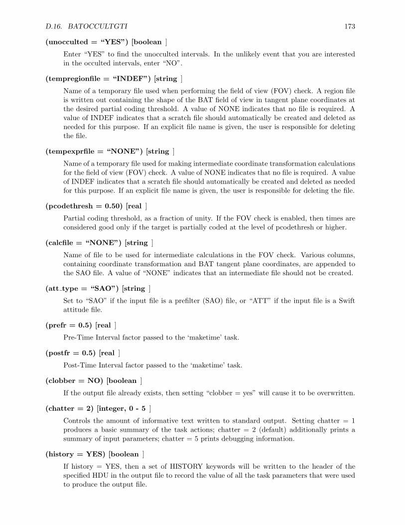
D.16. BATOCCULTGTI 173
(unocculted = “YES”) [boolean ]
Enter “YES” to find the unocculted intervals. In the unlikely event that you are interestedin the occulted intervals, enter “NO”.
(tempregionfile = “INDEF”) [string ]
Name of a temporary file used when performing the field of view (FOV) check. A region fileis written out containing the shape of the BAT field of view in tangent plane coordinates atthe desired partial coding threshold. A value of NONE indicates that no file is required. Avalue of INDEF indicates that a scratch file should automatically be created and deleted asneeded for this purpose. If an explicit file name is given, the user is responsible for deletingthe file.
(tempexprfile = “NONE”) [string ]
Name of a temporary file used for making intermediate coordinate transformation calculationsfor the field of view (FOV) check. A value of NONE indicates that no file is required. A valueof INDEF indicates that a scratch file should automatically be created and deleted as neededfor this purpose. If an explicit file name is given, the user is responsible for deleting the file.
(pcodethresh = 0.50) [real ]
Partial coding threshold, as a fraction of unity. If the FOV check is enabled, then times areconsidered good only if the target is partially coded at the level of pcodethresh or higher.
(calcfile = “NONE”) [string ]
Name of file to be used for intermediate calculations in the FOV check. Various columns,containing coordinate transformation and BAT tangent plane coordinates, are appended tothe SAO file. A value of “NONE” indicates that an intermediate file should not be created.
(att type = “SAO”) [string ]
Set to “SAO” if the input file is a prefilter (SAO) file, or “ATT” if the input file is a Swiftattitude file.
(prefr = 0.5) [real ]
Pre-Time Interval factor passed to the ‘maketime’ task.
(postfr = 0.5) [real ]
Post-Time Interval factor passed to the ‘maketime’ task.
(clobber = NO) [boolean ]
If the output file already exists, then setting “clobber = yes” will cause it to be overwritten.
(chatter = 2) [integer, 0 - 5 ]
Controls the amount of informative text written to standard output. Setting chatter = 1produces a basic summary of the task actions; chatter = 2 (default) additionally prints asummary of input parameters; chatter = 5 prints debugging information.
(history = YES) [boolean ]
If history = YES, then a set of HISTORY keywords will be written to the header of thespecified HDU in the output file to record the value of all the task parameters that were usedto produce the output file.

174 APPENDIX D. BAT SOFTWARE TOOL REFERENCE
D.16.5 EXAMPLES
1. Computes a good time interval for the Crab.
batoccultgti sw00111622000sao.fits.gz crab.gti 83.6332 22.0145
D.16.6 SEE ALSO
batoccultmap, maketime
D.16.7 LAST MODIFIED
Sep 2006
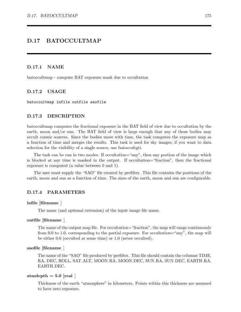
D.17. BATOCCULTMAP 175
D.17 BATOCCULTMAP
D.17.1 NAME
batoccultmap - compute BAT exposure mask due to occultation
D.17.2 USAGE
batoccultmap infile outfile saofile
D.17.3 DESCRIPTION
batoccultmap computes the fractional exposure in the BAT field of view due to occultation by theearth, moon and/or sun. The BAT field of view is large enough that any of these bodies mayoccult cosmic sources. Since the bodies move with time, the task computes the exposure map asa function of time and merges the results. This task is used for sky images; if you want to dataselection for the visibility of a single source, use batoccultgti.
The task can be run in two modes. If occultation=“any”, then any portion of the image whichis blocked at any time is masked in the output. If occultation=“fraction”, then the fractionalexposure is computed (a value between 0 and 1).
The user must supply the “SAO” file created by prefilter. This file contains the positions of theearth, moon and sun as a function of time. The sizes of the earth, moon and sun are configurable.
D.17.4 PARAMETERS
infile [filename ]
The name (and optional extension) of the input image file name.
outfile [filename ]
The name of the output map file. For occultation=“fraction”, the map will range continuouslyfrom 0.0 to 1.0, corresponding to the partial exposure. For occultation=“any”, the map willbe either 0.0 (occulted at some time) or 1.0 (never occulted).
saofile [filename ]
The name of the “SAO” file produced by prefilter. This file should contain the columns TIME,RA, DEC, ROLL, SAT ALT, MOON RA, MOON DEC, SUN RA, SUN DEC, EARTH RA,EARTH DEC.
atmdepth = 5.0 [real ]
Thickness of the earth “atmosphere” in kilometers. Points within this thickness are assumedto have zero exposure.
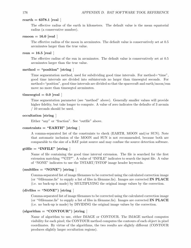
176 APPENDIX D. BAT SOFTWARE TOOL REFERENCE
rearth = 6378.1 [real ]
The effective radius of the earth in kilometers. The default value is the mean equatorialradius (a conservative number).
rmoon = 16.0 [real ]
The effective radius of the moon in arcminutes. The default value is conservatively set at 0.5arcminutes larger than the true value.
rsun = 16.5 [real ]
The effective radius of the sun in arcminutes. The default value is conservatively set at 0.5arcminutes larger than the true value.
method = “position” [string ]
Time segmentation method, used for subdividing good time intervals. For method=“time”,good time intervals are divided into subintervals no larger than timesegtol seconds. Formethod=“position”, good time intervals are divided so that the spacecraft and earth/moon/sunmove no more than timesegtol arcminutes.
timesegtol = 0.0 [real ]
Time segmentation parameter (see “method” above). Generally smaller values will providehigher fidelity, but take longer to compute. A value of zero indicates the defaults of 3 arcmin/ 10 seconds should be used.
occultation [string ]
Either “any” or “fraction”. See “outfile” above.
constraints = “EARTH” [string ]
A comma-separated list of the constraints to check (EARTH, MOON and/or SUN). Notethat automatic inclusion of the MOON and SUN is not recommended, because both arecomparable to the size of a BAT point source and may confuse the source detection software.
gtifile = “INFILE” [string ]
Name of file containing the good time interval extension. The file is searched for the firstextension matching “*GTI*”. A value of “INFILE” indicates to search the input file. A valueof “NONE” indicates to use the TSTART/TSTOP image header keywords.
(multfiles = “NONE”) [string ]
Comma-separated list of image filenames to be corrected using the calculated correction image(or “@filename.lis” to supply a list of files in filename.lis). Images are corrected IN PLACE(i.e. no back-up is made) by MULTIPLYING the original image values by the correction.
(divfiles = “NONE”) [string ]
Comma-separated list of image filenames to be corrected using the calculated correction image(or “@filename.lis” to supply a list of files in filename.lis). Images are corrected IN PLACE(i.e. no back-up is made) by DIVIDING the original image values by the correction.
(algorithm = “CONTOUR”) [string ]
Name of algorithm to use, either IMAGE or CONTOUR. The IMAGE method computesvisibility for each pixel; the CONTOUR method computes the contours of each object in pixelcoordinates. By virtue of the algorithms, the two results are slightly different (CONTOURproduces slightly larger occultation regions).
D.17. BATOCCULTMAP 177
(clobber = NO) [boolean ]
If the output file already exists, then setting “clobber = yes” will cause it to be overwritten.
(chatter = 2) [integer, 0 - 5 ]
Controls the amount of informative text written to standard output. Setting chatter = 1produces a basic summary of the task actions; chatter = 2 (default) additionally prints asummary of input parameters; chatter = 5 prints debugging information.
(history = YES) [boolean ]
If history = YES, then a set of HISTORY keywords will be written to the header of thespecified HDU in the output file to record the value of all the task parameters that were usedto produce the output file.
D.17.5 EXAMPLES
1. Computes the fractional exposure map for the primary HDU of sky.img. Good time intervalsare subdivided so that the spacecraft attitude/earth/moon/sun do not move more than 3 arcmin(the default).
batoccultmap sky.img occult.img sw00111622000sao.fits.gz \method=position occultation=fraction
D.17.6 SEE ALSO
batoccultgti
D.17.7 LAST MODIFIED
Apr 2007
178 APPENDIX D. BAT SOFTWARE TOOL REFERENCE
D.18 BATPHASYSERR
D.18.1 NAME
batphasyserr - apply BAT spectral systematic error vector
D.18.2 USAGE
batphasyserr infile syserrfile
D.18.3 DESCRIPTION
batphasyserr adds the BAT systematic error vector to a BAT spectral file. The systematic er-ror vector contains an estimate of the fractional systematic error in each BAT spectral channel.Normally this information comes from the BAT calibration database (CALDB).
The task handles the differences between type I and type II spectral files transparently. It alsoresamples the systematic error template to the energy bin edges of the input spectrum (this is doneby pure averaging).
D.18.4 PARAMETERS
infile [filename ]
Input/output spectral file. The file should be an OGIP-standard type I or type II spectralfile. The DATE-OBS keyword is used to query the CALDB. The file is modified in place. Ifnecessary, the SYS ERR column is created, and the SYS ERR keyword is deleted.
syserrfile [filename ]
Name of the systematic error vector file to use. Normally this should be set to “CALDB” sothat the current best estimate of the BAT spectral systematic error is used for the date ofthe given infile.
(chatter = 2) [integer, 0 - 5 ]
Controls the amount of informative text written to standard output.
D.18.5 EXAMPLES
1. Create the SYS ERR column in a spectral file named myspectrum.pha.
batphasyserr myspectrum.pha CALDB
The systematic error vector is retrieved from the calibration database.

D.18. BATPHASYSERR 179
D.18.6 SEE ALSO
batupdatephakw
D.18.7 LAST MODIFIED
Apr 2006
180 APPENDIX D. BAT SOFTWARE TOOL REFERENCE
D.19 BATTBLOCKS
D.19.1 NAME
battblocks - estimate interesting Bayesian Blocks and burst durations
• for time-variable data
D.19.2 USAGE
battblocks infile outfile
D.19.3 DESCRIPTION
battblocks estimates interesting time intervals (GTIs) based on time variable event or rate data. Itdoes this using the Bayesian Block algorithm, which is intended to robustly compute time intervalsbased on Bayesian analysis. (see Scargle 1998)
The user provides event data or a single-channel binned light curve. The light curve should be astandard OGIP light curve FITS file (i.e. contain the proper HDUCLASn keywords which identifywhether the light curve is background subtracted or not). Both RATE and COUNT type lightcurves are supported. It must be possible to multiply RATE by the TIMEDEL per-bin exposureto arrive at counts per bin. If the light curve has been background subtracted, then the ERRORcolumn must be present.
battblocks relies on the keyword information in the input file as being correct. In particular,HDUCLAS1 should be “EVENTS” or “LIGHTCURVE”, depending on the input file type. For lightcurves, HDUCLAS2 should be “NET” or “TOTAL” depending on whether the file is backgroundsubtracted. For light curves, HDUCLAS3 should be “RATE” or “COUNT”, although the user canoverride this with the hduclas3 parameter. There must also be a way to determine the per-sampleexposure, either with the standard TIMEDEL keyword, or a column named either TIMEDEL orEXPOSURE.
The Bayesian block algorithm can be used to estimate time intervals for any time series. Forbursts, it can also estimate several measures of the burst duration, and the interval of the peakflux. The burst duration is estimated by locating bracketing background intervals, and then locatingintervals which enclose 90% and 50% of the total counts. These are stored in the ‘durfile’ withextension names GTI T90 and GTI T50. Users should be aware that these algorithms are sensitiveto systematic variations in the background. Some care must be taken to filter the incoming lightcurve. Users can also choose their own percentage fluence with the ‘txx’ keyword; the result isstored in the GTI TXX extension.
The interval of the peak flux is estimated by sliding a time window across the light curve orevent data and finding the epoch with the highest counts. The user can select the size of thewindow. The corresponding GTI is written to ‘durfile’ with the extension name ‘GTI PEAK’.
D.19. BATTBLOCKS 181
For these measures, the user can request that battblocks perform background subtraction.The background is estimated based on the first and last Bayesian block intervals, and linearlyinterpolated to other points.
The global analysis time grows quadratically: as the input file size doubles, the computationtime quadruples, and so on. Users can perform a local Bayesian block analysis by setting tlookbackto a non-zero time window size. Only data within the time window at a particular instant areconsidered for the analysis at that instant. When tlookback is used, the resulting blocks areanalyzed in a second pass to further consolidate blocks larger than the window size. Users of eventdata can also adjust the ‘nspill’ parameter to decimate the events, at the expense of decreasing thetime resolution proportionately.
D.19.4 PARAMETERS
infile [filename ]
Input file name containing event data or light curve data. Events must be sorted in increasingtime order. Light curve data must be OGIP-format (containing the HDUCLASn keywords),and either have the columns TIME and COUNTS (binned counts); or TIME, RATE andERROR (binned data with error bars). Only single channel light curves are supported.
outfile [filename ]
Name of output good time interval file.
(durfile = ‘NONE’) [filename ]
Name of output duration measures. If durfile is ‘NONE’ then the duration measures are notcomputed or written. GTI tables with extensions ‘GTI T90’, ‘GTI T50’ and ‘GTI PEAK’are created.
(nspill = 128) [integer ]
Number of events to skip per analysis cell. ‘nspill’ events are grouped into one cell beforeBayesian analysis. Ignored for binned data.
(gaussian = INDEF) [string ]
Boolean which determines whether the Bayesian blocks computation is performed using Gaus-sian statistics or not. A value of INDEF causes battblocks to use Gaussian statistics forbackground-subtracted light curves, and Poissonian statistics otherwise. If “yes”, then theERROR column must exist in the input file. Ignored for event data.
(txx = 0.0) [real ]
User-specified percentage of burst to estimate the duration for. By default 90% (GTI T90)and 50% (GTI T50) fluence intervals are computed, but users can choose another percentagepoint as well (stored as GTI TXX). The interval is not estimated if txx is set to 0.0.
(tpeak = 1.0) [real ]
Size of sliding window, in seconds, used to determine the interval of the peak count rate.
(tlookback = 0.0) [real ]
A non-zero value indicates the lookback time window in seconds, for the local bayesian blockanalysis. Smaller values will run faster, at the expense of generating more blocks (no blockwill be larger than tlookback). The lookback time is converted to a number of samples
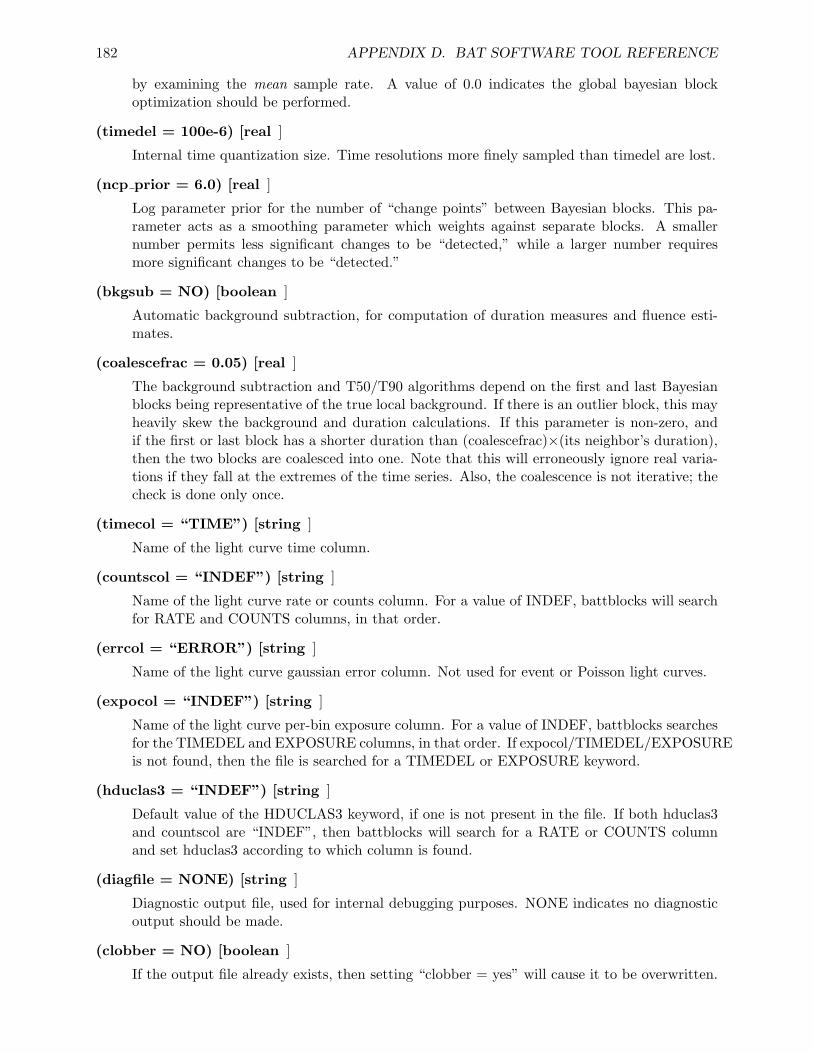
182 APPENDIX D. BAT SOFTWARE TOOL REFERENCE
by examining the mean sample rate. A value of 0.0 indicates the global bayesian blockoptimization should be performed.
(timedel = 100e-6) [real ]
Internal time quantization size. Time resolutions more finely sampled than timedel are lost.
(ncp prior = 6.0) [real ]
Log parameter prior for the number of “change points” between Bayesian blocks. This pa-rameter acts as a smoothing parameter which weights against separate blocks. A smallernumber permits less significant changes to be “detected,” while a larger number requiresmore significant changes to be “detected.”
(bkgsub = NO) [boolean ]
Automatic background subtraction, for computation of duration measures and fluence esti-mates.
(coalescefrac = 0.05) [real ]
The background subtraction and T50/T90 algorithms depend on the first and last Bayesianblocks being representative of the true local background. If there is an outlier block, this mayheavily skew the background and duration calculations. If this parameter is non-zero, andif the first or last block has a shorter duration than (coalescefrac)×(its neighbor’s duration),then the two blocks are coalesced into one. Note that this will erroneously ignore real varia-tions if they fall at the extremes of the time series. Also, the coalescence is not iterative; thecheck is done only once.
(timecol = “TIME”) [string ]
Name of the light curve time column.
(countscol = “INDEF”) [string ]
Name of the light curve rate or counts column. For a value of INDEF, battblocks will searchfor RATE and COUNTS columns, in that order.
(errcol = “ERROR”) [string ]
Name of the light curve gaussian error column. Not used for event or Poisson light curves.
(expocol = “INDEF”) [string ]
Name of the light curve per-bin exposure column. For a value of INDEF, battblocks searchesfor the TIMEDEL and EXPOSURE columns, in that order. If expocol/TIMEDEL/EXPOSUREis not found, then the file is searched for a TIMEDEL or EXPOSURE keyword.
(hduclas3 = “INDEF”) [string ]
Default value of the HDUCLAS3 keyword, if one is not present in the file. If both hduclas3and countscol are “INDEF”, then battblocks will search for a RATE or COUNTS columnand set hduclas3 according to which column is found.
(diagfile = NONE) [string ]
Diagnostic output file, used for internal debugging purposes. NONE indicates no diagnosticoutput should be made.
(clobber = NO) [boolean ]
If the output file already exists, then setting “clobber = yes” will cause it to be overwritten.
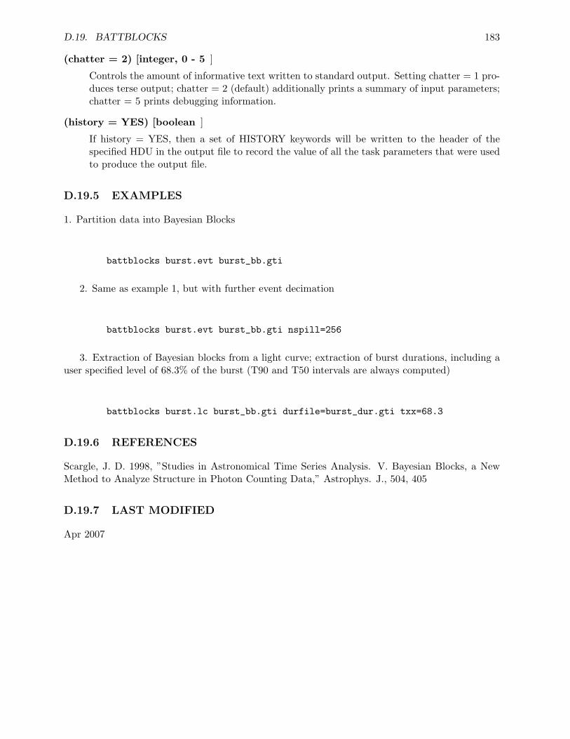
D.19. BATTBLOCKS 183
(chatter = 2) [integer, 0 - 5 ]
Controls the amount of informative text written to standard output. Setting chatter = 1 pro-duces terse output; chatter = 2 (default) additionally prints a summary of input parameters;chatter = 5 prints debugging information.
(history = YES) [boolean ]
If history = YES, then a set of HISTORY keywords will be written to the header of thespecified HDU in the output file to record the value of all the task parameters that were usedto produce the output file.
D.19.5 EXAMPLES
1. Partition data into Bayesian Blocks
battblocks burst.evt burst_bb.gti
2. Same as example 1, but with further event decimation
battblocks burst.evt burst_bb.gti nspill=256
3. Extraction of Bayesian blocks from a light curve; extraction of burst durations, including auser specified level of 68.3% of the burst (T90 and T50 intervals are always computed)
battblocks burst.lc burst_bb.gti durfile=burst_dur.gti txx=68.3
D.19.6 REFERENCES
Scargle, J. D. 1998, ”Studies in Astronomical Time Series Analysis. V. Bayesian Blocks, a NewMethod to Analyze Structure in Photon Counting Data,” Astrophys. J., 504, 405
D.19.7 LAST MODIFIED
Apr 2007
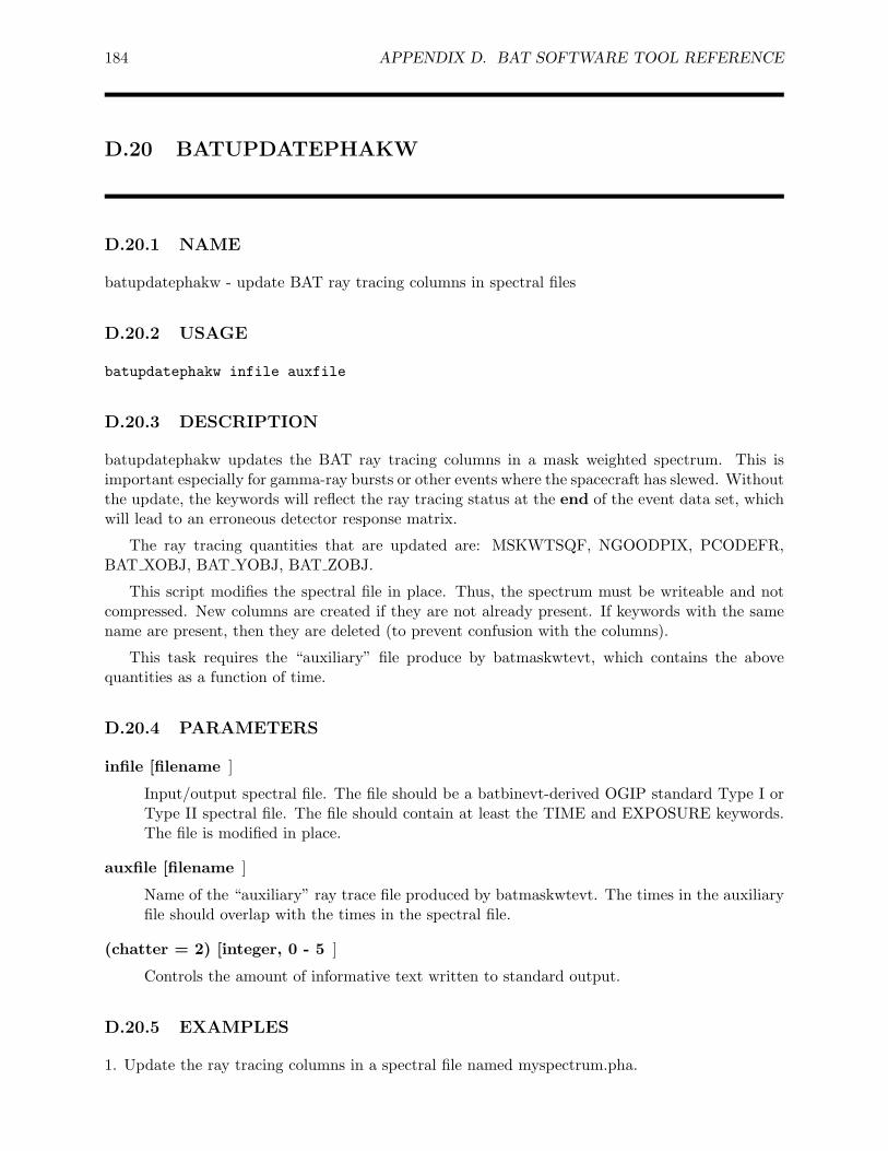
184 APPENDIX D. BAT SOFTWARE TOOL REFERENCE
D.20 BATUPDATEPHAKW
D.20.1 NAME
batupdatephakw - update BAT ray tracing columns in spectral files
D.20.2 USAGE
batupdatephakw infile auxfile
D.20.3 DESCRIPTION
batupdatephakw updates the BAT ray tracing columns in a mask weighted spectrum. This isimportant especially for gamma-ray bursts or other events where the spacecraft has slewed. Withoutthe update, the keywords will reflect the ray tracing status at the end of the event data set, whichwill lead to an erroneous detector response matrix.
The ray tracing quantities that are updated are: MSKWTSQF, NGOODPIX, PCODEFR,BAT XOBJ, BAT YOBJ, BAT ZOBJ.
This script modifies the spectral file in place. Thus, the spectrum must be writeable and notcompressed. New columns are created if they are not already present. If keywords with the samename are present, then they are deleted (to prevent confusion with the columns).
This task requires the “auxiliary” file produce by batmaskwtevt, which contains the abovequantities as a function of time.
D.20.4 PARAMETERS
infile [filename ]
Input/output spectral file. The file should be a batbinevt-derived OGIP standard Type I orType II spectral file. The file should contain at least the TIME and EXPOSURE keywords.The file is modified in place.
auxfile [filename ]
Name of the “auxiliary” ray trace file produced by batmaskwtevt. The times in the auxiliaryfile should overlap with the times in the spectral file.
(chatter = 2) [integer, 0 - 5 ]
Controls the amount of informative text written to standard output.
D.20.5 EXAMPLES
1. Update the ray tracing columns in a spectral file named myspectrum.pha.

D.20. BATUPDATEPHAKW 185
batupdatephakw myspectrum.pha auxfile.fits
auxfile.fits is the “auxiliary” file produced by batmaskwtevt.
D.20.6 SEE ALSO
batmaskwtevt
D.20.7 LAST MODIFIED
Aug 2006
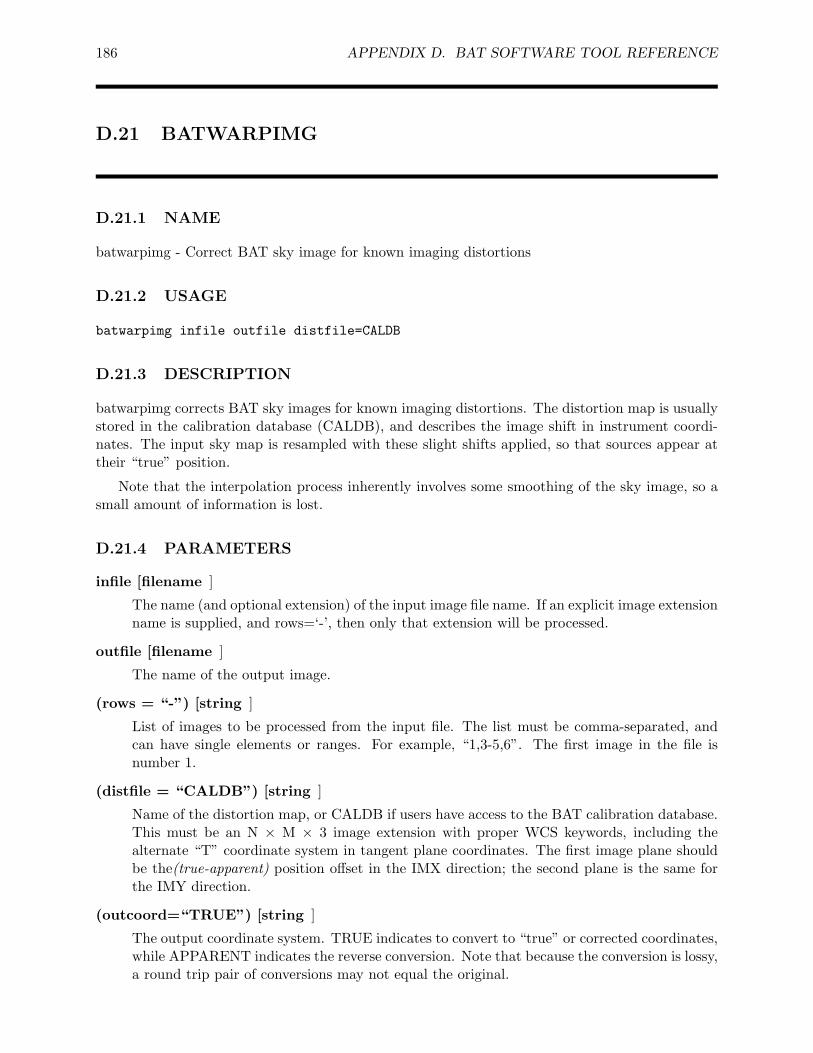
186 APPENDIX D. BAT SOFTWARE TOOL REFERENCE
D.21 BATWARPIMG
D.21.1 NAME
batwarpimg - Correct BAT sky image for known imaging distortions
D.21.2 USAGE
batwarpimg infile outfile distfile=CALDB
D.21.3 DESCRIPTION
batwarpimg corrects BAT sky images for known imaging distortions. The distortion map is usuallystored in the calibration database (CALDB), and describes the image shift in instrument coordi-nates. The input sky map is resampled with these slight shifts applied, so that sources appear attheir “true” position.
Note that the interpolation process inherently involves some smoothing of the sky image, so asmall amount of information is lost.
D.21.4 PARAMETERS
infile [filename ]
The name (and optional extension) of the input image file name. If an explicit image extensionname is supplied, and rows=‘-’, then only that extension will be processed.
outfile [filename ]
The name of the output image.
(rows = “-”) [string ]
List of images to be processed from the input file. The list must be comma-separated, andcan have single elements or ranges. For example, “1,3-5,6”. The first image in the file isnumber 1.
(distfile = “CALDB”) [string ]
Name of the distortion map, or CALDB if users have access to the BAT calibration database.This must be an N × M × 3 image extension with proper WCS keywords, including thealternate “T” coordinate system in tangent plane coordinates. The first image plane shouldbe the(true-apparent) position offset in the IMX direction; the second plane is the same forthe IMY direction.
(outcoord=“TRUE”) [string ]
The output coordinate system. TRUE indicates to convert to “true” or corrected coordinates,while APPARENT indicates the reverse conversion. Note that because the conversion is lossy,a round trip pair of conversions may not equal the original.
D.21. BATWARPIMG 187
(copyall=“YES”) [boolean ]
Indicates whether to copy all other extensions. If yes, then the unprocessed extensions arecopied untouched. If no, then only the processed extensions are saved.
(clobber = NO) [boolean ]
If the output file already exists, then setting “clobber = yes” will cause it to be overwritten.
(chatter = 2) [integer, 0 - 5 ]
Controls the amount of informative text written to standard output. Setting chatter = 1produces a basic summary of the task actions; chatter = 2 (default) additionally prints asummary of input parameters; chatter = 5 prints debugging information.
(history = YES) [boolean ]
If history = YES, then a set of HISTORY keywords will be written to the header of thespecified HDU in the output file to record the value of all the task parameters that were usedto produce the output file.
D.21.5 EXAMPLES
1. Correct an image for distortions.
batwarpimg input.fits output.fits distfile=CALDB
D.21.6 SEE ALSO
batwarpcoord
D.21.7 LAST MODIFIED
Apr 2007

188 APPENDIX D. BAT SOFTWARE TOOL REFERENCE
Appendix E
BAT Software Revision History
This appendix contains the release notes for the BAT ground software. The software was released inincrements known as “builds,” which were delivered to the Swift Science Center and the HEASARCfor integration into the overall FTOOLS/HEASoft packages for the public.
For public releases, the public release date was about one month after the BAT build wasdelivered. The first public build was Build 14.
Please note that BAT builds 1 and 2 were delivered informally with no release notes.
E.1 Swift BAT Software Build 3: 2002 Nov 15
Tools included in this release:
batbinevt (CM)batcelldetect (CM)bateconvert (HK)batfftimage (CM)batmaskwtevt (CM)batmaskwtimg (CM)
E.2 Swift BAT Software Build 4: 2003 Feb 25
Tools included in this release:
batbinevt (CM) [modified since release 3.0]batcelldetect (CM) [modified since release 3.0]batdph2dpi (SA) [new tool]bateconvert (HK)batevt2dpi (SA) [new tool]batfftimage (CM) [modified since release 3.0]batgse2dpi (SA) [new tool]bathotpix (CM) [new tool]batid2xy (HK) [new tool]batmaskwtevt (CM) [modified since release 3.0]batmaskwtimg (CM) [modified since release 3.0]
189
190 APPENDIX E. BAT SOFTWARE REVISION HISTORY
Modifications to tools which were released in Build 3
batbinevt (existing tool)
* accepts EBOUNDS extension acceptable as input for energy bins* writes EBOUNDS extension to output file* outputs should be OGIP-conforming light curves and spectra* various bug fixes
batcelldetect (existing tool)
* accumulated quantities now are double precision* output is now more script friendly* various bug fixes
batfftimage (existing tool)
* add code to handle near-field imaging, useful in integration andtest;
* aperture parameter is now hidden, refers to refdata* corrections to calculations of coordinate systems* correction to image for aberration due to autocollimation* bug fix to computation of partial coding map
batmaskwtimg (existing tool)
* now handles spacecraft attitude conversion, and sky coordinates inRA/DEC.
* aperture parameter is now hidden, refers to refdata* output keywords are now BAT_RA/BAT_DEC instead of
mission-level keywords which may have loaded meanings* various bug fixes and internal changes
batmaskwtevt (existing tool)
* now handles spacecraft attitude conversion, and sky coordinates inRA/DEC.
* handles case of moving spacecraft* aperture parameter is now hidden, refers to refdata* output keywords are now BAT_RA/BAT_DEC instead of
mission-level keywords which may have loaded meanings* various bug fixes and internal changes
E.3. SWIFT BAT SOFTWARE BUILD 5: 2003 MAY 27 191
E.3 Swift BAT Software Build 5: 2003 May 27
Tools included in this release:
batbinevt (CM) [modifications since release 4.0]batbkgclean (HK) [new tool]batcelldetect (CM) [significant modifications since release 4.0]batdph2dpi (SA) [minor modifications since release 4.0]batdrmgen (AP) [new tool]bateconvert (HK) [significant modifications since release 4.0]batevt2dpi (SA) [minor modifications since release 4.0]batfftimage (CM) [modifications since release 4.0]batgse2dpi (SA) [minor modifications since release 4.0]bathotpix (CM) [minor modifications since release 4.0]batid2xy (HK)batmasktaglc (SA) [new tool]batmasktagpha (SA) [new tool]batmaskwtevt (CM) [modified since release 4.0]batmaskwtimg (CM) [modified since release 4.0]batsumdph (SA) [new tool]
Librariesmpfit - NEW LIBRARY
This library implements the public domain MINPACK-1 least squaresfitting routines, as originally authored by the Argonned group,translated to C by Steven Moshier, and enhanced by C. Markwardt.Users supply a fitting function, and (optionally) parameterconstraints, and mpfit() performs the least squares fit.
Modifications to tools which were released in Build 4
batbinevt -- CHANGED
The gtifile parameter is now implemented, and the user can specifyarbitrary Good Time Intervals. The "userbin" time binning method isimplemented. Multiple input files are permitted, usingexpand_item_list(). Spatial filtering via a detector quality map(detmask) has been implemented. Outputs have been changed to moreclosely adhere to OGIP standards. GTI extensions are written.Sanity checks are done, to be sure the user has already runbatmaskwtevt and bateconvert.
batcelldetect - SIGNIFICANT CHANGES
The tool produces an output catalog in FITS format.
Point spread fitting is now implemented using the mpfit library.The shape of the PSF is gaussian.
192 APPENDIX E. BAT SOFTWARE REVISION HISTORY
Output coordinates now include pixels (IMXPIX,IMYPIX), tangent-planecoordinates (IMX,IMY), and celestial (RA,DEC). Celestialcoordinates are only produced if the input image has the proper WCSkeywords attached (namely, if an attitude file was supplied to thebatfftimage task). Parameter uncertainties are estimated forquantities (see _ERR columns). Also, the time, exposure, and otherstatus parameters are written to the catalog.
An input catalog is accepted (new incatalog parameter). Sourceswhich are not in the field of view are removed from the catalog whentransferred to the output. Sources which are in the field of vieware retained, and fitted with fixed position during the PSF fittingstage. Known sources are also excluded from the pixel-detectionstage.
The imagemask parameter has been removed, in favor of the pcodefileand pcodethresh parameters. Now users can supply a partial codingmap, or any map for that matter, and a threshold. Source detectionoutside the threshold region will be rejected.
batdph2dpi -- MINOR CHANGES
* Modified batdph2dpi.c to recognize the level_ranges string "1-3,5"as well as "1-3,5-5". Also called the subroutine headas_parstamp to addthe HISTORY keywords to the dpi file generated.
* Modified par file and code to change "rownumber" to"rows" and "level_ranges" to "levels"
* Fixed bug that caused program to crash if it was tryingto overwrite an existing file with clobber=no. Also replaced a loop ofcalls to fits_read_col by a more efficient single call.
bateconvert -- SIGNIFICANT CHANGES
Added code to perform a quadratic correction to the linear gain conversionalready in the code. If calmode = QUADRATIC, then two new files are readin: residfile, which contains the residuals between the quadratic andlinear gain fits, and pulserfile, which contains the gain coefficientsbetween electronic pulser and energy. The linear correction is stillperformed and the quadratic correction added to it.
batevt2dpi -- MINOR CHANGES
Changed binning expression to correct a bug in the previous script.
batfftimage - CHANGED
The tool already accepts and uses the spacecraft attitude file (and
E.4. SWIFT BAT SOFTWARE BUILD 6: 2003 AUG 25 193
a TELDEF file) in order to determine the orientation of the outputimage. The CROTA2 keyword is used instead of the PC_* keywords, forcompatibility with old viewers. Default teldef files have beenadded. The origin_z parameter has been added, for support of groundactivities.
The meaning of detector "quality" used in the detmask parameter hasbeen changed so that 0 is good, in accordance with OGIPrecommendations.
batgse2dpi -- MINOR CHANGES
* Corrected bug in how the code handles disabled detector modules* The meaning of detector "quality" used in the detmask parameter has
been changed so that 0 is good, in accordance with OGIP recommendations.* Added code to actually write out HISTORY keywords.* Other minor bug fixes.
bathotpix - CHANGED
The meaning of detector "quality" used in the detmask parameter hasbeen changed so that 0 is good, in accordance with OGIPrecommendations.
batmaskwtimg/evt - CHANGEDTool now ouptuts BAT_X/Y/ZOBJ under all circumstances. The gapvalparameter controls what value gaps are assigned in the output map.
E.4 Swift BAT Software Build 6: 2003 Aug 25
Tools included in this release:
*batbinevt (CM) [minor modifications since release 5.0]*batcelldetect (CM) [significant modifications since release 5.0]*batclean (HK) [formerly batbkgclean -- significant mods since release 5.0]batdph2dpi (SA)*batdph2pha (HK) [new tool]*batdrmgen (AP) [significant modifications since release 5.0]bateconvert (HK) [minor modifications since release 5.0]batevt2dpi (SA)*batfftimage (CM) [significant modifications since release 5.0]batgse2dpi (SA/HK) [minor modifications since release 5.0]bathotpix (CM) [minor modifications since release 5.0]batid2xy (HK) [minor modifications since release 5.0]*batmasktaglc (SA/HK) [significant modifications since release 5.0]batmasktagpha (SA/HK) [minor modifications since release 5.0]*batmaskwtevt (CM) [significant modifications since release 5.0]*batmaskwtimg (CM) [significant modifications since release 5.0]
194 APPENDIX E. BAT SOFTWARE REVISION HISTORY
batsumdph (SA)*battblocks (CM) [new tool]
Tools marked with a * are either new or have had significant updates infunctionality since Build 5.0.
Librariesbatutils - NEW LIBRARY
This library contains general purpose BAT functions including thecaldb access routines (wrappers which call HDgtcalf), the batidconvertfunction used by many tools and several functions used by one or moretools. Also a general-purpose include file bat_gswdev.h is includedhere. Several of these tools have been moved from other libraries.
Modifications to tools which were released in Build 4
batbinevt -- SIGNIFICANT CHANGES
This tool has undergone significant revisions. batbinevt now acceptsas input both events and BAT detector plane histograms (DPHs). Itproduces as output any one of light curve, spectrum, DPH, or detectorplane image (DPI). The DPIs can be of two types: one per imageextension (outtype=DPI); or many in a single binary table (DPITAB).Users can choose whether the output should be weighted or not (new’weighted’ parameter); or whether the output should be in counts orcounts/s. Input column names are now selectable.
For time binning, the ’gti’ time binning method now preserves all binedges, even when the are adjoining; a new ’infile’ binning methodpreserves the original time binning of the input if it is a DPH.Energy bins can be specified on the command line, or accessed viaCALDB. This tool now uses the headas_gti.c library routine instead ofits internal one.
batcelldetect -- SIGNIFICANT CHANGES
batcelldetect can now read and analyze multiple images in a singlerun. The images must be in a single file, either as one per imageextension, or in a binary table of images. The output catalog willcontain a vector of fluxes instead of a scalar. batcelldetect nowhandles the SOURCE_ID catalog column.
The requirements for detecting a new source have been made morestringent. The background variance must be significant; also, aminimum number of pixels must be found (4).
batcelldetect can now be restricted to only positive peaks (pospeaksparameter). Coordinates in the GRMC and BAT Science theta/phi systems
E.4. SWIFT BAT SOFTWARE BUILD 6: 2003 AUG 25 195
are now computed, as well as the partial coding fraction if pcodefileis provided. batcelldetect can now output a region file with sourcepositions, compatible with both FV/POW and DS9. In DS9, the sourcename will be printed next to the marked position.
batclean -- SIGNIFICANT CHANGES
The tool now cleans sources as well as background. It reads an inputcatalog as created by batcelldetect to determine the source locationin BAT coordinates. It then calls batmaskwtimg, which produces aforward projection of the source onto the focal plane. Also addedsome additional output options. Added caldb access.
batdrmgen -- SIGNIFICANT CHANGES
New with this version:1) The program now accepts many different incident energy bin edges such
as LIN, LOG, USER (custom bin edges) and a default (INDEF) spectrumwith some of the bin edges adjusted for the Cd and Te K edges.
2) Calibration parameters are now taken from a FITS file where eachcombination of incident enery, tanx and tany has a corresponding listof parameters that are to be used to generate the correct response.
3) CALDB has been implemented, so if the user types "calfile = caldb" or"depthfile = caldb", the program will use the caldb utility to selectthe parameter files appropriate for the data to be analysed.
4) The incident energy range upper limit has been increased to 500 keV.5) Off-axis response has been implemented.6) Response now includes the escape peaks for Cd and Te in the spectra
Limitations of this version:1) Keywords representing the state of the PHA data (whether or not
various corrections have been applied) have not been implemented.2) The cal parameters file currently has identical entries for each cell
- we must change the file to include the right spectral parameters.
bateconvert -- MINOR CHANGES
Added caldb access for residual and pulser files. Changed the formatin which these files are read in. Fixed a bug in the application ofthe quadratic fit. Added caldb access.
batfftimage - CHANGED
batfftimage can now read and analyze multiple images in a single run.The images must be in a single file, either as one per imageextension, or in a binary table of images. The output file willcontain multiple sky images in separate extensions.
CALDB access routines have been added (via batutils) to read theaperture and teldef files. Corrections to some coordinate
196 APPENDIX E. BAT SOFTWARE REVISION HISTORY
calculations. The keyword for autocollimation correction is nowACOLAPP instead of ACOLCOR.
batgse2dpi -- MINOR CHANGES
Changed some array allocations to allow compilation on other operatingsystems. Fixed bug in the code that was improperly indexing thewindow cut arrays if there were missing rows in the windows lookuptable. Now the code reads and uses the block/dm/side/det values in thewindows table for indexing.
bathotpix - MINOR CHANGES
Some changes to support a new library routine for reading images.
batid2xy -- MINOR CHANGES
Added more functionality to the tool to allow the user to specifydetector by DETX/DETY and detector ID as well as Block, DM, Side,Detector.
batmasktaglc -- SIGNIFICANT CHANGES
Changed much of how the mask weighting is read in and used. Changedthe algorithm by which source, background and errors are calculated.Added background column. Generally cleaned up the code. Added caldbaccess.
batmasktagpha -- MINOR CHANGES
Added caldb access. Fixed some bugs in the code.
batmaskwtimg/evt - CHANGED
There a number of new corrections that can be applied in the maskweight calculation: flatfield (combined cosine projection, r-squared,and side illumination effects), pcode (partial coding), ndets (numberof detectors), cosine (cosine projection effect only), rsquare(r-squared effects only). The user can also choose unbalanced images(0 to 1) instead of balanced (-1 to 1). The user can choose whichdirection the weights should apply: backward (default) or forward.’forward’ creates a mask weight map which most closely resembles thetrue detector plane image; while ’backward’ is meant for use in maskweighted sums.
The detmask parameter has been added, to aid in calculating the ndetscorrection. CALDB access routines have been added (via batutils) toread the aperture and teldef files.
E.5. SWIFT BAT SOFTWARE BUILD 7: 2003 DEC 04 197
E.5 Swift BAT Software Build 7: 2003 Dec 04
Tools included in this release:* batbinevt (CM) [minor modifications since release 6.0]* batcelldetect (CM) [minor modifications since release 6.0]* batclean (HK) [minor modifications since release 6.0]* batdph2dpi (SA)* batdph2pha (HK)* batdrmgen (AP) [minor modifications since release 6.0]* bateconvert (HK)* baterebin (LB) [New tool]* batfftimage (CM) [significant modifications since release 6.0]* batgse2dpi (SA/HK)* bathotpix (CM) [minor modifications since release 6.0]* batid2xy (HK)* batmasktaglc (SA/HK)* batmaskwtevt (CM) [significant modifications since release 6.0]* batmaskwtimg (CM) [significant modifications since release 6.0]* batsumdph (SA)* battblocks (CM) [significant modifications since release 6.0]
The following tools have been deleted from the release because theyare obsolete and superseded by additional functionality in batbinevt:
* batevt2dpi (SA)* batmasktagpha (SA/HK)
Modifications to tools which were released in Build 4
All tasks: change to HDpar_stamp() in place of headas_parstamp().
batbinevt -- MINOR CHANGES
batbinevt - v1.3 - Minor cleanups and bug fixes. Detector planeimages are now written starting with the primary extension. Outputunits and column descriptors are now more appropriate.
batcelldetect -- MINOR CHANGES
batcelldetect - v1.4 - Minor changes. Output units are now moreappropriate. If the input image is in units of "count/s" then theoutput column is RATE, not COUNTS.
batclean -- MINOR CHANGES
A new parameter "eff_edge" was added and support for an "opaque"correction was added. These are for support for an alternativeversion of the mask weighting program called maskwtimg_op.
Also a correction was made to solve a problem whereby fits made
198 APPENDIX E. BAT SOFTWARE REVISION HISTORY
to detector planes with low counts came out too small. This involvedaltering the count values and their weights in the fit according to aprescription by K. Mighell (Ap J 518, p. 380, 1999). This appears toimprove the cleaning of sources with low background.
batdrmgen -- MINOR CHANGES
Build 7 version 12/3/03 - Ann Parsons, Derek Hullinger, Craig Markwardt(very similar to Build 6)
New with this version:1)Uses the keyword maskwtsqr, as read from the header of the phafile’s SPECTRUM extension, to determine the effective number ofdetectors included in the response.2) Bug fixes to the default input energy bin edges. (The K edgeenergies were wrong)
Remaining limitations of this version:1) Keywords representing the state of the PHA data (whether or notvarious corrections have been applied) have not been implemented.2) The cal parameters file currently has identical entries for eachcell - we must change the file to include the right spectral parameters.
bateconvert -- MINOR CHANGES
Fixed bug that was corrupting the input file if the cal files were notvalid files. (The code wasn’t going to cleanup properly if the routinethat tried to read the cal files returned a non-zero status.)
batfftimage - SIGNIFICANT CHANGES
batfftimage - v1.3 - Extensive changes. The task now accepts abackground image (or images) and performs background subtractionbefore deconvolution. Units are maintained. Images with NULL pixelshave those pixels ignored. The user can now specify which column tooperate on, if the input is a table of images. The task is compatiblewith the new attitude library version by Ed Pier. Bug fixes andcleanups.
bathotpix - MINOR CHANGES
bathotpix - v1.1 - Minor changes. The "guard band" calculation hasbeen changed.
batmaskwtimg/evt - SIGNIFICANT CHANGES
batmaskwtevt / img - v1.1 - Extensive changes. A new algorithm forcalculating mask transmission functions is included (maskwtimg_op),activated by passing the corrections=opaque parameter. The detectorquality map is now applied correctly. A bug was fixed in the way that
E.6. SWIFT BAT SOFTWARE BUILD 8: 2004 MAY 24 199
corrections are applied to negative weights. Small fixes andcleanups. The task is compile-compatible with the new attitudelibrary version by Ed Pier.
battblocks - SIGNIFICANT CHANGES
battblocks - v1.0 - Major changes. The cost function for data withgaussian errors has been revised, and can be considerednon-experimental. Burst duration measures are now computed, includingT90, T50, and Tnn, where nn is choosable by the user (with the txxparameter). Also the interval around the peak flux is estimated (theinterval size is determined by the tpeak= parameter). Computations ofthese measures is enabled by the durfile= parameter, which specifiedan output GTI file. The durations are also written to the masteroutput GTI as keywords. A second major area of improvement is theaddition of a "progressive" Bayesian blocks implementation, enabled bythe tlookback= parameter, which should be much faster for most timeseries. [ This implementation requires two iterations. ]
E.6 Swift BAT Software Build 8: 2004 May 24
1. Outstanding Issues
This build includes several revisions to optimize for speed andaccuracy of the BAT tools. However, there are several things notincluded.
a) BAT teldef file is still "Z-pointed" (it should bestraightforward to deliver a new version on a short timescale)
b) A mechanism to construct multiple spectra during slews does notexist. A new interface must be developed between batmaskwtevt andbatbinevt to pass time-variable auxiliary information to theresponse matrix generator.
c) These tools do not take into account all of the file formatchanges required by HEASARC.
2. Summary of tools
There are no new tools in this release, only revisions to existingtools.
Revised tools
batbinevt -* auto quantization of photon energies;* cosmetic improvements to output statistics
200 APPENDIX E. BAT SOFTWARE REVISION HISTORY
batcelldetect -* print RA/DEC to console if attitude info is available;* column name changes for consistency with the BAT flight
catalog naming, and with batmaskwtevt/batdrmgen* bug fix of TNULLing output catalog, when fitting multiple-images* account for the possibility of a flipped image
batclean -* column name changes for consistency with the BAT flight
catalog naming, and with batmaskwtevt/batdrmgen
batdrmgen* extensive changes to improve computational efficiency* new "depth distribution" format is more compact on disk
batfftimage* new default shows images with East = left
batmaskwtevt/img* significant raytracing code speed-ups (approx. factor 10 faster)* simplication of "corrections" parameter; new value of "default"
gives the BAT team’s recommended corrections* keyword name changes for consistency with batdrmgen
batsumdph* extensive code cleanups and bug fixes
battblocks* more extensive error checking, and bug fixes
Tasks batevt2dpi, batgse2dpi, and batmasktagpha are consideredobsolete, and/or not for end users.
E.7 Swift BAT Software Build 9: 2004 Aug 11
1. Overview
This build contains significant changes from the previous build. Mostgamma-ray burst analysis will depend on features and bug fixes in thisbuild.
This release compiles and runs its unit tests successfully on Linux,Mac OSX, and Alpha OSF. See below for some issues with the Alpha.
A new "X-pointed" teldef file is delivered in the CALDB.
2. Summary of tool changes
E.7. SWIFT BAT SOFTWARE BUILD 9: 2004 AUG 11 201
There is one new tool in this release, batgse2dph, but it is internalonly to the BAT team.
Revised tools
batbinevt -* INTERFACE CHANGE: ’dph_counts’ parameter is now ’countscol’* INTERFACE CHANGE: output column is now TIME_STOP instead of TIME_END* now copies correction keywords ending in "APP" from the input
mask weight file to the output* now ignores NULL input counts values* bug fixes
batcelldetect -* INTERFACE CHANGES: new ’posfit’, ’srcfit’, ’najdpix’ and
’srcdetect’ parameters, for fine-grained control of the task* now copies correction keywords ending in "APP" from the input
image to columns in the output catalog* allow configurable source names, with an index number* allow niter=0, which only computes which sources are in the F.O.V.* ignore NULL pixel values* output descriptive comments of each catalog column* bug fixes
batclean -* INTERFACE CHANGES: new ’wtmapin’ and ’wtmapout’ keywords to aid in
error analysis* recognizes either the SOURCE_ID or CATNUM catalog column name* default aperture and teldef files taken from CALDB now
batdrmgen -* now relies on batmaskwtevt/img to compute corrections* add transparency of lead mask to the model
bateconvert -* bug fix
batfftimage -* CRITICAL BUG FIX: for images that were partially flipped
when handedness=left* user-selected oversampling is now permitted* many corrections can now be applied to the image, there is a
"default" correction with the BAT team recommended corrections* major code restructuring* other small bug fixes
batgse2dph -* BAT team tool for converting non-flight calibration data to
flight-like format
202 APPENDIX E. BAT SOFTWARE REVISION HISTORY
bathotpix -* Can now handle rate data* bug fix
batmasktaglc -* INTERFACE CHANGE: add ’corrections’ parameter for cosine,
partial coding and flatfielding adjustments.* Add support for multiple mask weight maps.* More robust estimate of T50/90, also including uncertainty estimates.* Optimization
Tasks batevt2dpi, batgse2dpi, batgse2dph, and batmasktagpha areconsidered obsolete, and/or not for end users.
E.8 Swift BAT Software Build 10: 2004 Oct 10
1. Overview
This build is more or less a clean-up build. There are some bug fixesand small improvements, but there was some effort to avoid changeswhere they weren’t needed.
"Revision 2" release notes contains some additional enhancements overthe first delivery, to batmaskwtimg and batmaskwtevt. It alsoincludes some documentation updates.
"Revision 3" provides a note that the task baterebin is notfunctioning properly (see section 3)
This release compiles and runs its unit tests successfully on Linux,Mac OSX, and Alpha OSF. See below for some issues with the Alpha.
The "X-pointed" teldef file is delivered in the "test" CALDB used forunit testing.
2. Summary of tool changes
There are no new tools.
Revised tools
batbinevt* produce FLUXMETH keyword in output files (flux extraction method)* bug fix for output of CHANTYPE keyword (was writing column
name instead of PHA/PI)
E.9. SWIFT BAT SOFTWARE BUILD 11: 2004 NOV 19 203
batdrmgen -* do not read the TIMEZERO keyword.* read response matrix instead of RESP_ESCALE vector for
input energy scale. (maintain old compatibility as well)* reorganize CALDB query routines* check FLUXMETH keyword of input spectrum* query CALDB for mu-tau parameters separately* use the FLUXMETH keyword to select caldb database* add ’mode’ parameter to the parfile for proper FTOOLS operation
baterebin* has unfixed bugs which produce incorrect results.
batfftimage -* incorporate correct z-dependence for the mask weighting
correction, including an algorithm dependent correction factor.INTERFACE CHANGE: maskwtswgain parameter* documentation corrections
bathotpix -* write a bad pixel table in the second extension
batmaskwtevt -* incorporate correct z-dependence for the mask weighting
correction, including an algorithm dependent correction factor.INTERFACE CHANGE: maskwtswgain parameterINTERFACE CHANGE: maskwtcol parameters allows user choice of mask
weight column name* Code reorganization to match batmaskwtimg
batmaskwtimg -* Allow batch processing with an input source catalog; the output
is written as successive image extensions.
battblocks -* bug fix for MJDREF being zero
Tasks batevt2dpi, batgse2dpi, batgse2dph, and batmasktagpha areconsidered obsolete, and/or not for end users.
E.9 Swift BAT Software Build 11: 2004 Nov 19
1. Overview
MIKE: I made changes over the weekend (Dec 18-19). There is one unittest data set, batcelldetect, which has changed.
In this build we are delivering baterebin. As you recall, baterebinwas withdrawn from build 10 because it wasn’t working right. In this
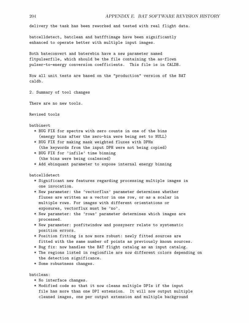
204 APPENDIX E. BAT SOFTWARE REVISION HISTORY
delivery the task has been reworked and tested with real flight data.
batcelldetect, batclean and batfftimage have been significantlyenhanced to operate better with multiple input images.
Both bateconvert and baterebin have a new parameter namedfltpulserfile, which should be the file containing the as-flownpulser-to-energy conversion coefficients. This file is in CALDB.
Now all unit tests are based on the "production" version of the BATcaldb.
2. Summary of tool changes
There are no new tools.
Revised tools
batbinevt* BUG FIX for spectra with zero counts in one of the bins
(energy bins after the zero-bin were being set to NULL)* BUG FIX for making mask weighted fluxes with DPHs
(the keywords from the input DPH were not being copied)* BUG FIX for ’infile’ time binning
(the bins were being coalesced)* Add ebinquant parameter to expose internal energy binning
batcelldetect* Significant new features regarding processing multiple images in
one invocation.* New parameter: the ’vectorflux’ parameter determines whether
fluxes are written as a vector in one row, or as a scalar inmultiple rows. For images with different orientations orexposures, vectorflux must be ’no’.
* New parameter: the ’rows’ parameter determines which images areprocessed.
* New parameter: posfitwindow and possyserr relate to systematicposition errors.
* Position fitting is now more robust: newly fitted sources arefitted with the same number of points as previously known sources.
* Bug fix: now handles the BAT flight catalog as an input catalog.* The regions listed in regionfile are now different colors depending on
the detection significance.* Some robustness changes.
batclean:* No interface changes.* Modified code so that it now cleans multiple DPIs if the input
file has more than one DPI extension. It will now output multiplecleaned images, one per output extension and multiple background
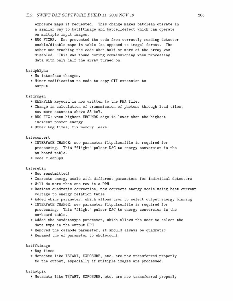
E.9. SWIFT BAT SOFTWARE BUILD 11: 2004 NOV 19 205
exposure maps if requested. This change makes batclean operate ina similar way to batfftimage and batcelldetect which can operateon multiple input images.
* BUG FIXES. One prevented the code from correctly reading detectorenable/disable maps in table (as opposed to image) format. Theother was crashing the code when half or more of the array wasdisabled. This was found during commissioning when processingdata with only half the array turned on.
batdph2pha:* No interface changes.* Minor modification to code to copy GTI extension to
output.
batdrmgen* RESPFILE keyword is now written to the PHA file.* Change in calculation of transmission of photons through lead tiles:
now more accurate above 88 keV.* BUG FIX: when highest EBOUNDS edge is lower than the highest
incident photon energy.* Other bug fixes, fix memory leaks.
bateconvert* INTERFACE CHANGE: new parameter fltpulserfile is required for
processing. This "flight" pulser DAC to energy conversion is theon-board table.
* Code cleanups
baterebin* Now resubmitted!* Corrects energy scale with different parameters for individual detectors* Will do more than one row in a DPH* Besides quadratic correction, now corrects energy scale using best current
voltage to energy relation table* Added ebins parameter, which allows user to select output energy binning* INTERFACE CHANGE: new parameter fltpulserfile is required for
processing. This "flight" pulser DAC to energy conversion is theon-board table.
* Added the outdatatype parameter, which allows the user to select thedata type in the output DPH
* Removed the calmode parameter, it should always be quadratic* Renamed the wf parameter to wholecount
batfftimage* Bug fixes* Metadata like TSTART, EXPOSURE, etc. are now transferred properly
to the output, especially if multiple images are processed.
bathotpix* Metadata like TSTART, EXPOSURE, etc. are now transferred properly
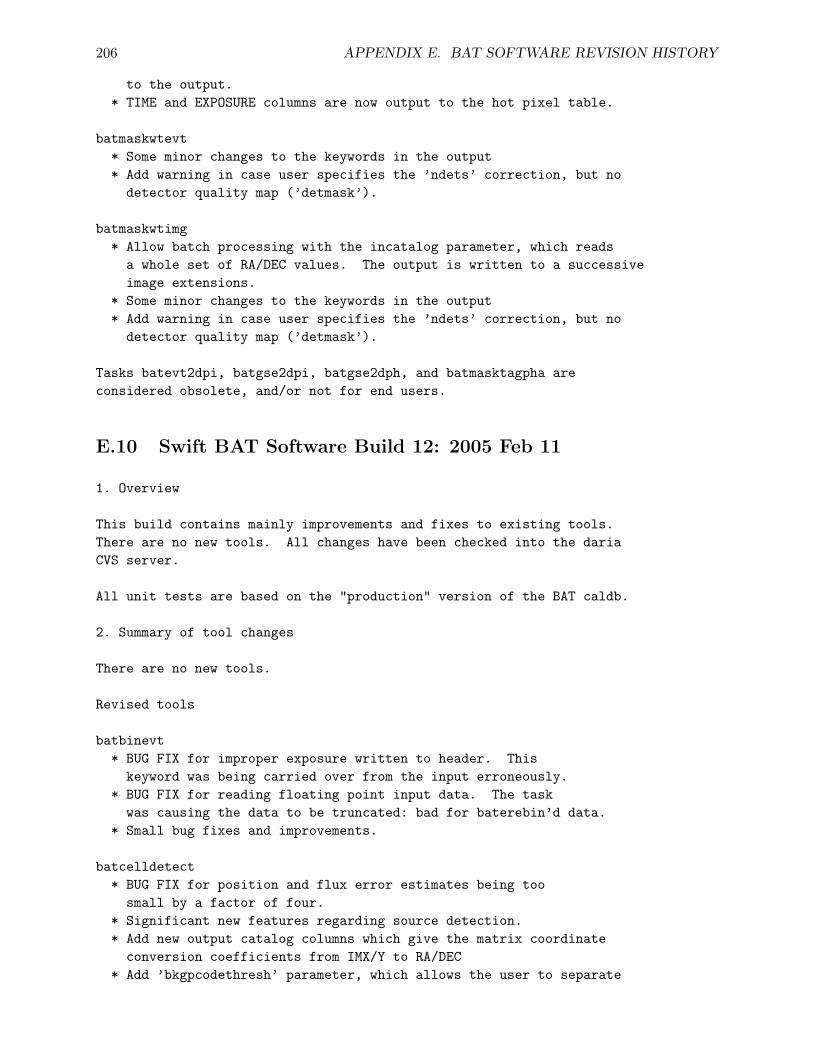
206 APPENDIX E. BAT SOFTWARE REVISION HISTORY
to the output.* TIME and EXPOSURE columns are now output to the hot pixel table.
batmaskwtevt* Some minor changes to the keywords in the output* Add warning in case user specifies the ’ndets’ correction, but no
detector quality map (’detmask’).
batmaskwtimg* Allow batch processing with the incatalog parameter, which reads
a whole set of RA/DEC values. The output is written to a successiveimage extensions.
* Some minor changes to the keywords in the output* Add warning in case user specifies the ’ndets’ correction, but no
detector quality map (’detmask’).
Tasks batevt2dpi, batgse2dpi, batgse2dph, and batmasktagpha areconsidered obsolete, and/or not for end users.
E.10 Swift BAT Software Build 12: 2005 Feb 11
1. Overview
This build contains mainly improvements and fixes to existing tools.There are no new tools. All changes have been checked into the dariaCVS server.
All unit tests are based on the "production" version of the BAT caldb.
2. Summary of tool changes
There are no new tools.
Revised tools
batbinevt* BUG FIX for improper exposure written to header. This
keyword was being carried over from the input erroneously.* BUG FIX for reading floating point input data. The task
was causing the data to be truncated: bad for baterebin’d data.* Small bug fixes and improvements.
batcelldetect* BUG FIX for position and flux error estimates being too
small by a factor of four.* Significant new features regarding source detection.* Add new output catalog columns which give the matrix coordinate
conversion coefficients from IMX/Y to RA/DEC* Add ’bkgpcodethresh’ parameter, which allows the user to separate
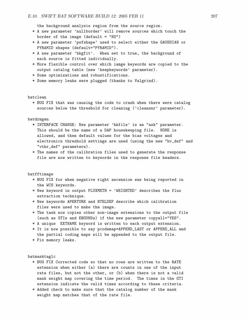
E.10. SWIFT BAT SOFTWARE BUILD 12: 2005 FEB 11 207
the background analysis region from the source region.* A new parameter ’nullborder’ will remove sources which touch the
border of the image (default = "NO")* A new parameter ’psfshape’ used to select either the GAUSSIAN or
PYRAMID shapes (default="PYRAMID").* A new parameter ’bkgfit’. When set to true, the background of
each source is fitted individually.* More flexible control over which iamge keywords are copied to the
output catalog table (new ’keepkeywords’ parameter).* Some optimizations and robustifications.* Some memory leaks were plugged (thanks to Valgrind).
batclean* BUG FIX that was causing the code to crash when there were catalog
sources below the threshold for cleaning (’cleansnr’ parameter).
batdrmgen* INTERFACE CHANGE: New parameter ’hkfile’ is an "ask" parameter.
This should be the name of a DAP housekeeping file. NONE isallowed, and then default values for the bias voltages andelectronics threshold settings are used (using the new "hv_def" and"vthr_def" parameters).
* The names of the calibration files used to generate the responsefile are now written to keywords in the response file headers.
batfftimage* BUG FIX for when negative right ascension was being reported in
the WCS keywords.* New keyword in output FLUXMETH = ’WEIGHTED’ describes the flux
extraction technique.* New keywords APERTURE and BTELDEF describe which calibration
files were used to make the image.* The task now copies other non-image extensions to the output file
(such as GTIs and EBOUNDs) if the new parameter copyall="YES".* A unique EXTNAME keyword is written to each output extension.* It is now possible to say pcodemap=APPEND_LAST or APPEND_ALL and
the partial coding maps will be appended to the output file.* Fix memory leaks.
batmasktaglc* BUG FIX Corrected code so that no rows are written to the RATE
extension when either (a) there are counts in one of the inputrate files, but not the other, or (b) when there is not a validmask weight map covering the time period. The times in the GTIextension indicate the valid times according to these criteria.
* Added check to make sure that the catalog number of the maskweight map matches that of the rate file.
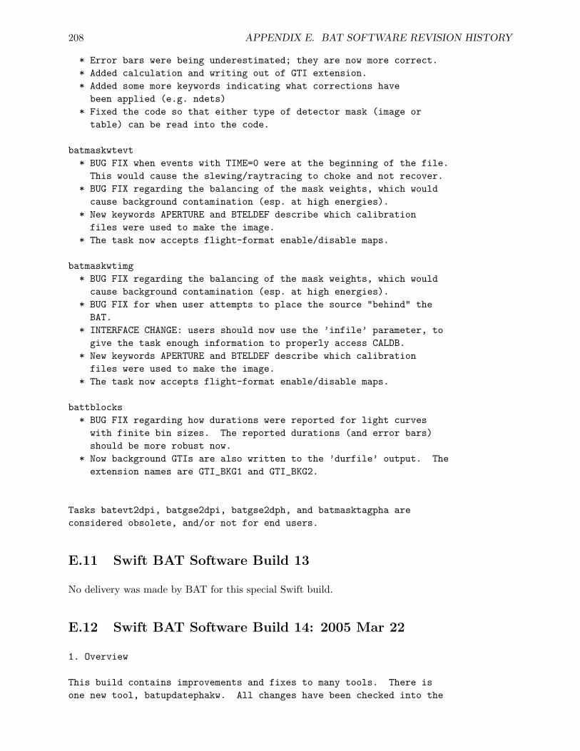
208 APPENDIX E. BAT SOFTWARE REVISION HISTORY
* Error bars were being underestimated; they are now more correct.* Added calculation and writing out of GTI extension.* Added some more keywords indicating what corrections have
been applied (e.g. ndets)* Fixed the code so that either type of detector mask (image or
table) can be read into the code.
batmaskwtevt* BUG FIX when events with TIME=0 were at the beginning of the file.
This would cause the slewing/raytracing to choke and not recover.* BUG FIX regarding the balancing of the mask weights, which would
cause background contamination (esp. at high energies).* New keywords APERTURE and BTELDEF describe which calibration
files were used to make the image.* The task now accepts flight-format enable/disable maps.
batmaskwtimg* BUG FIX regarding the balancing of the mask weights, which would
cause background contamination (esp. at high energies).* BUG FIX for when user attempts to place the source "behind" the
BAT.* INTERFACE CHANGE: users should now use the ’infile’ parameter, to
give the task enough information to properly access CALDB.* New keywords APERTURE and BTELDEF describe which calibration
files were used to make the image.* The task now accepts flight-format enable/disable maps.
battblocks* BUG FIX regarding how durations were reported for light curves
with finite bin sizes. The reported durations (and error bars)should be more robust now.
* Now background GTIs are also written to the ’durfile’ output. Theextension names are GTI_BKG1 and GTI_BKG2.
Tasks batevt2dpi, batgse2dpi, batgse2dph, and batmasktagpha areconsidered obsolete, and/or not for end users.
E.11 Swift BAT Software Build 13
No delivery was made by BAT for this special Swift build.
E.12 Swift BAT Software Build 14: 2005 Mar 22
1. Overview
This build contains improvements and fixes to many tools. There isone new tool, batupdatephakw. All changes have been checked into the
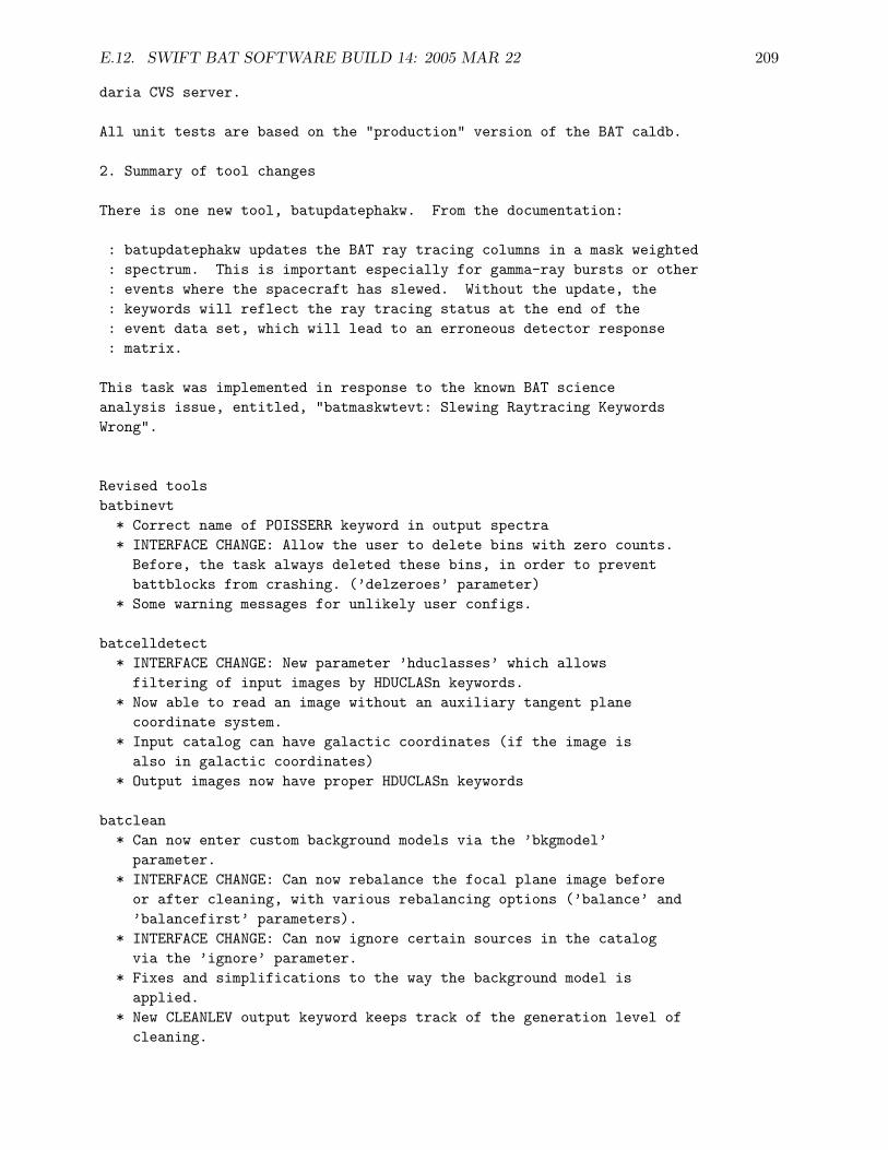
E.12. SWIFT BAT SOFTWARE BUILD 14: 2005 MAR 22 209
daria CVS server.
All unit tests are based on the "production" version of the BAT caldb.
2. Summary of tool changes
There is one new tool, batupdatephakw. From the documentation:
: batupdatephakw updates the BAT ray tracing columns in a mask weighted: spectrum. This is important especially for gamma-ray bursts or other: events where the spacecraft has slewed. Without the update, the: keywords will reflect the ray tracing status at the end of the: event data set, which will lead to an erroneous detector response: matrix.
This task was implemented in response to the known BAT scienceanalysis issue, entitled, "batmaskwtevt: Slewing Raytracing KeywordsWrong".
Revised toolsbatbinevt
* Correct name of POISSERR keyword in output spectra* INTERFACE CHANGE: Allow the user to delete bins with zero counts.
Before, the task always deleted these bins, in order to preventbattblocks from crashing. (’delzeroes’ parameter)
* Some warning messages for unlikely user configs.
batcelldetect* INTERFACE CHANGE: New parameter ’hduclasses’ which allows
filtering of input images by HDUCLASn keywords.* Now able to read an image without an auxiliary tangent plane
coordinate system.* Input catalog can have galactic coordinates (if the image is
also in galactic coordinates)* Output images now have proper HDUCLASn keywords
batclean* Can now enter custom background models via the ’bkgmodel’
parameter.* INTERFACE CHANGE: Can now rebalance the focal plane image before
or after cleaning, with various rebalancing options (’balance’ and’balancefirst’ parameters).
* INTERFACE CHANGE: Can now ignore certain sources in the catalogvia the ’ignore’ parameter.
* Fixes and simplifications to the way the background model isapplied.
* New CLEANLEV output keyword keeps track of the generation level ofcleaning.
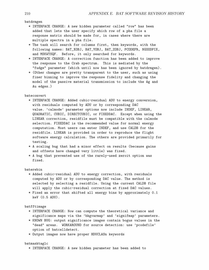
210 APPENDIX E. BAT SOFTWARE REVISION HISTORY
batdrmgen* INTERFACE CHANGE: A new hidden parameter called "row" has been
added that lets the user specify which row of a pha file aresponse matrix should be made for, in cases where there aremultiple spectra in a pha file.
* The task will search for columns first, then keywords, with thefollowing names: BAT_XOBJ, BAT_YOBJ, BAT_ZOBJ, PCODEFR, NGOODPIX,and MSKWTSQF. Before, it only searched for keywords.
* INTERFACE CHANGE: A correction function has been added to improvethe response to the Crab spectrum. This is mediated by the"fudge" parameter (which until now has been ignored by batdrmgen).
* (Other changes are pretty transparent to the user, such as usingfiner binning to improve the response fidelity and changing themodel of the passive material transmission to include the Ag andAu edges.)
bateconvert* INTERFACE CHANGE: Added cubic-residual ADU to energy conversion,
with residuals computed by ADU or by corresponding DACvalue. ’calmode’ parameter options now include INDEF, LINEAR,QUADRATIC, CUBIC, DIRECTCUBIC, or FIXEDDAC. Except when using theLINEAR correction, residfile must be compatible with the calmodeselection. FIXEDDAC is the recommended value for normal energycomputation. Most users can enter INDEF, and use CALDB for theresidfile. LINEAR is provided in order to reproduce the flightsoftware energy calculation. The others are provided primarily fortesting.
* A scaling bug that had a minor effect on results (because gainsand offsets have changed very little) was fixed.
* A bug that prevented use of the rarely-used zeroit option wasfixed.
baterebin* Added cubic-residual ADU to energy correction, with residuals
computed by ADU or by corresponding DAC value. The method isselected by selecting a residfile. Using the current CALDB filewill apply the cubic-residual correction at fixed DAC values.
* Fixed an error that shifted all energy bins by approximately 0.1keV (0.5 ADU).
batfftimage* INTERFACE CHANGE: Now can compute the theoretical variance and
significance maps via the ’bkgvarmap’ and ’signifmap’ parameters.* KNOWN BUG: output significance images contain bogus values in the
"dead" areas. WORKAROUND for source detection: use ’pcodefile’option of batcelldetect.
* Output images now have proper HDUCLASn keywords
batmasktaglc* INTERFACE CHANGE: A new hidden parameter has been added to
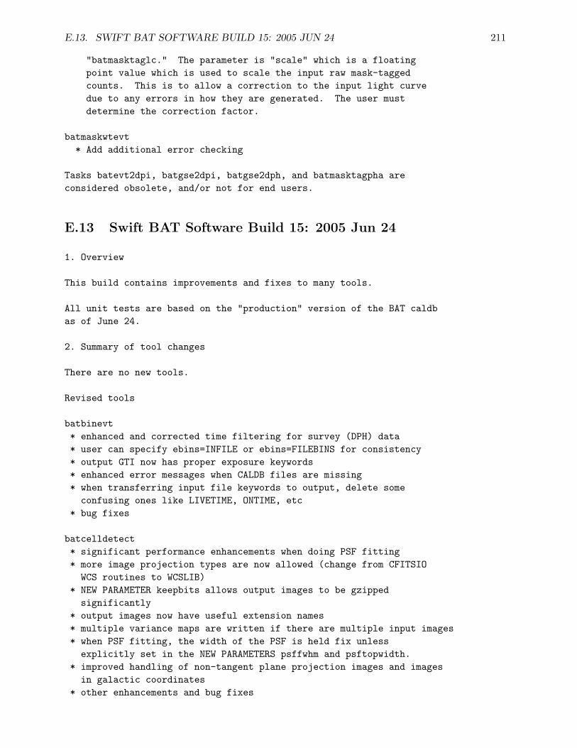
E.13. SWIFT BAT SOFTWARE BUILD 15: 2005 JUN 24 211
"batmasktaglc." The parameter is "scale" which is a floatingpoint value which is used to scale the input raw mask-taggedcounts. This is to allow a correction to the input light curvedue to any errors in how they are generated. The user mustdetermine the correction factor.
batmaskwtevt* Add additional error checking
Tasks batevt2dpi, batgse2dpi, batgse2dph, and batmasktagpha areconsidered obsolete, and/or not for end users.
E.13 Swift BAT Software Build 15: 2005 Jun 24
1. Overview
This build contains improvements and fixes to many tools.
All unit tests are based on the "production" version of the BAT caldbas of June 24.
2. Summary of tool changes
There are no new tools.
Revised tools
batbinevt* enhanced and corrected time filtering for survey (DPH) data* user can specify ebins=INFILE or ebins=FILEBINS for consistency* output GTI now has proper exposure keywords* enhanced error messages when CALDB files are missing* when transferring input file keywords to output, delete some
confusing ones like LIVETIME, ONTIME, etc* bug fixes
batcelldetect* significant performance enhancements when doing PSF fitting* more image projection types are now allowed (change from CFITSIO
WCS routines to WCSLIB)* NEW PARAMETER keepbits allows output images to be gzipped
significantly* output images now have useful extension names* multiple variance maps are written if there are multiple input images* when PSF fitting, the width of the PSF is held fix unless
explicitly set in the NEW PARAMETERS psffwhm and psftopwidth.* improved handling of non-tangent plane projection images and images
in galactic coordinates* other enhancements and bug fixes
212 APPENDIX E. BAT SOFTWARE REVISION HISTORY
batclean* balancing is now performed when outversion=’fit’* vector SNR columns are now handled* range images are now handled (correct statistics)
batdrmgen* added a better gain correction method, to better match
calibration peaks
baterebin* BUG FIX in cases where the output EBOUNDS extension has the wrong
number of rows* all extensions of the input are copied to the output now* warnings are error checks were revised
batfftimage* NEW PARAMETER keepbits allows output images to be gzipped
significantly (and is set by default)* enhanced error messages when CALDB files are missing* for pixels below the partial coding threshold, the significance
is now always set to NULL* NEW PARAMETER ’time’ allows user override of the image time
bathotpix* NEW PARAMETER ’row’ to allow selective image processing for multi-
image files
batmasktaglc* BUG FIX for handling of pipeline detector enable/disable maps
batmaskwtevt* additional error checking* enhanced error messages when CALDB files are missing
batmaskwtimg* enhanced error messages when CALDB files are missing* task now uses the image MIDPOINT TIME instead of start time
in order to be more consistent with batfftimage* additional error checking and documentation updates
battblocks* NEW PARAMETER coalescefrac, to improve the robustness of the first
and last time bins
Tasks batevt2dpi, batgse2dpi, batgse2dph, and batmasktagpha areconsidered obsolete, and/or not for end users.
E.14. SWIFT BAT SOFTWARE BUILD 16: 2005 SEP 20 213
E.14 Swift BAT Software Build 16: 2005 Sep 20
1. Overview
This build contains improvements and fixes to many tools. There arethree new tools: batoccultgti, batoccultmap, and batphasyserr.
All unit tests pass, and are based on the "production" version of theBAT caldb as of Sep 9.
2. Summary of tool changes
There are three new tools
batoccultgti
* this new task computes good time intervals that are unocculted bythe earth, moon, and/or sun. The user enters as input theobservation "prefilter" (or "SAO") file and the position of thesource. The output is a standard good time interval file which canbe used for selecting BAT survey data (it can be used as input tothe ’mgtime’ or ’batbinevt’ tasks).
This task is used when the source of interest is known.
batoccultmap
* this new task computes an exposure correction based on occultationsby the earth, moon and/or sun. The user enters as input theobservation "prefilter" (or "SAO") file and the image to becorrected. Portions of the image which are occulted by the earthor other bodies have their exposure reduced accordingly. Themotion of these bodies in the BAT field of view as a function oftime are accounted for as well.
This task is used when a blind image search will be performed, orif there are many sources being analyzed at the same time. Whenthe source is known in advance, unocculted data should be selectedusing batoccultgti instead.
batphasyserr
* this new task applies a systematic error vector to a user-generatedBAT spectrum (PHA file). By default the systematic error vector istaken from CALDB. Both type I and type II spectral formats arehandled. If the user binning does not match the systematic errortemplate, then the template is rebinned to match.
Revised tools
214 APPENDIX E. BAT SOFTWARE REVISION HISTORY
batbinevt* PARAMETER CHANGE: outtype, as detailed below* new output format: type I spectral format (for outtype="PHA1")* the type II format can be output by using outtype=PHA2* when outtype=PHA is given, then the output is either
type I, if only one output spectrum is produced ORtype II, if more than one output spectrum is produced
* THUS, THE DEFAULT SPECTRUM TYPE HAS CHANGED FROM TYPE II TO TYPE I* a warning is produced if the users asks for a COUNTS spectrum
of type II format; this is particularly poorly supported byOGIP/HEASARC downstream software
* remove some confusing WCS keywords held over from the original input* handle cases where the input file is corrupted or mishandled; for
example, if the GTI extension is missing from a DPH* proper exposure-type keywords are written to the GTI and EBOUNDS
extensions
batcelldetect* BUG FIX in the handling of multiple images in tangent plane
coordinates* BUG FIX in the handling of long catalog NAMEs and keyword strings* TDISPn keywords are written so that catalog entries are displayed
more readably* the task now uses the WCSLIB coordinate routines more fully
batclean* PARAMETER CHANGE: several apertures can be chosen from CALDB;
use the "CALDB:flux" aperture by default* NEW PARAMETER: snrcol so the user can choose which column to
use for S/N thresholding* BUG FIXes in the handling of long catalog NAMEs and null values* some code cleanups
batdrmgen* Added a better gain correction method to improve energy scale* Added more realistic energy-dependent resolution* The task now can correct for the "tile edge effect" more flexibly* REQUIRES new CALDB released with build 16
bateconvert* Changed limits on energy to -10 to +3276.8 keV
baterebin* NEW PARAMETER detmask, an optional input detector quality map* BUG FIXes to the handling of the upper and lower integral bins* Reduced number and apparent urgency of error messages* Added more diagnostic information
batfftimage
E.15. SWIFT BAT SOFTWARE BUILD 17: 2005 NOV 03 215
* PARAMETER CHANGE: several apertures can be chosen from CALDB;use the "CALDB:flux" aperture by default
batmasktaglc* PARAMETER CHANGE: scale=1.3 is a new scale factor to account
for the error in the flight software mask tagging* Task now writes a SCALEAPP keyword to record the scale factor used
batmaskwtevt* PARAMETER CHANGE: several apertures can be chosen from CALDB;
use the "CALDB:flux" aperture by default* BUG FIX for the flat field correction
NOTE: this fix means that previous analysis must be re-run
batmaskwtimg* PARAMETER CHANGE: several apertures can be chosen from CALDB;
use the "CALDB:flux" aperture by default* BUG FIX for the flat field correction
NOTE: this fix means that previous analysis must be re-run* NEW PARAMETER: outtype, which selects the filter applied to the
output image* NEW PARAMETER: combmeth, which controls how multiple output
images are combined (if at all)
batupdatephakw* the task now handles both type I and type II spectral files,
in order to be compatible with changes to batbinevt.
Tasks batevt2dpi, batgse2dpi, batgse2dph, and batmasktagpha areconsidered obsolete, and/or not for end users.
E.15 Swift BAT Software Build 17: 2005 Nov 03
1. Overview
This build contains improvements and fixes to many tools.
All unit tests pass, and are based on the "production" version of theBAT caldb as of Nov 3.
2. Summary of tool changes
Revised tools
batbinevt* The task now uses the HDUCLAS2 keyword to determine how errors
should be computed; for a batclean map with HDUCLAS2=’PREDICTED’
216 APPENDIX E. BAT SOFTWARE REVISION HISTORY
the errors are set to zero.* The task can now read both kinds of detector enable maps: table and image.* Some bug fixes related to writing the TOTCOUNT keyword
batcelldetect* The ERR_RAD column in the input catalog is now handled as documented: if
the ERR_RAD value is zero for a source, then the position is held fixed* The coordinate precision of images with non tangent plane projections
is better.
batclean* Bug fixes: the chi-square value is now correct; and NULL values are
handled correctly
Tasks batevt2dpi, batgse2dpi, batgse2dph, and batmasktagpha areconsidered obsolete, and/or not for end users.
E.16 Swift BAT Software Build 18: 2006 Mar 15
1. Overview
This build contains improvements and fixes to many tools.
All unit tests pass, and are based on the "production" version of theBAT CALDB, as released to the public.
2. Summary of tool changes
Revised tools
batbinevt* BUG FIX regarding the calculation of energy bins; the *top-most*
bin only would miss a 0.1 keV slice of the data* Improved checking for overlapping energy bins* Checking if input is a DPH of cleaned RESIDUALs (prevents erroneous
statistical uncertainties from being calculated)* Work around a BUG in XSPEC which transforms small error bars into
big (occurs when using a PREDICTED map)* Remove some Chandra Data Model keywords that become erroneous after
binning
batcelldetect* BUG FIX when ’nadjpix’ > 1; should only affect the chi-square values
reported* New parameters ’inbkgmap’ and ’inbkgvarmap’ which allow pre-computed
background information (saves computational time)* New parameter ’carryover’ which controls whether new sources are
carried over to subsequent images in a multi-image analysis* New PSF type: "TRUNCONE" for azimuthally averaged images
E.17. SWIFT BAT SOFTWARE BUILD 19: 2006 JUL 10 217
* Optimized for speed in the PSF-fitting stage* Check for tangent-plane coordinate system in images is more
complete now
batdrmgen* Improved error checking
baterebin* New parameter ’outmap’ for optional output detmask, with values
indicating various potential criteria for masking detectors* New parameters ’lowecare’ and ’highecare’ that determine the energy
range checked for two potential exclusion criteria
batmaskwtevt* New parameter ’pcodethresh’ which allows far off-axis sources to be
removed (instead of having very noisy points)
batoccultgti* Revise the parameter handling so that the use does not need to
know about, or delete, the required scratch files unless theywant to
* Correct behavior for the region file coordinate system designation* Add exception handling routines
batoccultmap* Now uses the new version of WCSLIB
batphasyserr* The task now adds some HISTORY information* Add exception handling routines
battblocks* Internal code clean-up
batupdatephakw* The task now adds some HISTORY information* Add exception handling routines
Tasks batevt2dpi, batgse2dpi, batgse2dph, and batmasktagpha areconsidered obsolete, and/or not for end users.
E.17 Swift BAT Software Build 19: 2006 Jul 10
1. Overview
This build contains one new BAT task, and improvements and fixes tomany tasks. It also discusses several non-BAT-related tasks whichare delivered by the BAT team.
218 APPENDIX E. BAT SOFTWARE REVISION HISTORY
All unit tests pass, and are based on the "production" version of theBAT CALDB, as released to the public.
2. Summary of tool changes
New tools
batwarpimg* New task which adjusts a BAT image for known non-linear image distortion* For source detection, batcelldetect should be used instead of this task
Revised tools
batbinevt* Bug fix to the way the final time bin was written, in some rare cases.* Bug fix to transfer the MJDREF* keywords properly, when combining GTIs* Bug fix to remove buffer overflow error tickled by the new parameter library* Primary HDU images are now labeled with HDUNAME instead of EXTNAME.
This is still compatible with standard CFITSIO and DS9.* New time binning algorithm, MATCHLC, which allows the time binning
of an existing light curve to be cloned.* Write NULL values in bins that have zero exposure (when minfracexp is 0)* Slight changes to error messages
batcelldetect* Bug fix: clustering of >2 sources during the PSF fit stage was done
improperly, and is now fixed* Bug fix: known bright sources which touch the border of the image were being
improperly detected as new sources* New feature: adds distortion correction to position reporting
(the distortion map is pointed to by the ’distfile’ which defaults to CALDB)* Internal changes of the use of the WCS library* Primary HDU images are now labeled with HDUNAME instead of EXTNAME.
This is still compatible with standard CFITSIO and DS9.* Catalog I/O is more forgiving if TUNIT/TNULL values are not present
batfftimage* Primary HDU images are now labeled with HDUNAME instead of EXTNAME.
This is still compatible with standard CFITSIO and DS9.
batmaskwtevt* New feature: adds distortion correction to position calculation
(the distortion map is pointed to by the ’distfile’ which defaults to CALDB)
batmaskwtimg* New feature: adds distortion correction to position calculation
(the distortion map is pointed to by the ’distfile’ which defaults to CALDB)
E.18. SWIFT BAT SOFTWARE BUILD 20: 2006 NOV 06 219
* Primary HDU images are now labeled with HDUNAME instead of EXTNAME.This is still compatible with standard CFITSIO and DS9.
batoccultgti* Additional error handling code
batoccultmap* Bug fix: when the earth is at the very edge of the FOV and exclusively in the
southern hemisphere, the whole FOV was accidentally blanked. Now fixed.* Primary HDU images are now labeled with HDUNAME instead of EXTNAME.
This is still compatible with standard CFITSIO and DS9.* Additional error checking for bogus inputs
batphasyserr* Additional error handling code
batupdatephakw* Additional error handling code
Tasks batevt2dpi, batgse2dpi, batgse2dph, and batmasktagpha areconsidered obsolete, and/or not for end users.
E.18 Swift BAT Software Build 20: 2006 Nov 06
1. Overview
This build contains one new BAT task, and improvements and fixes tomany tasks. It also discusses several non-BAT-related tasks whichare delivered by the BAT team.
All unit tests pass, and are based on a *NEW* version of theBAT CALDB, which can be found as described below.
2. Summary of tool changes
New tools
batdetmask* New task for establishing BAT global good/bad detectors for a given time
batglobalgti* New task for establishing BAT global good/bad science analysis time filter
batgrbproduct* New task which performs fully automatic gamma-ray burst analysis of BAT data
Revised tools
batbinevt
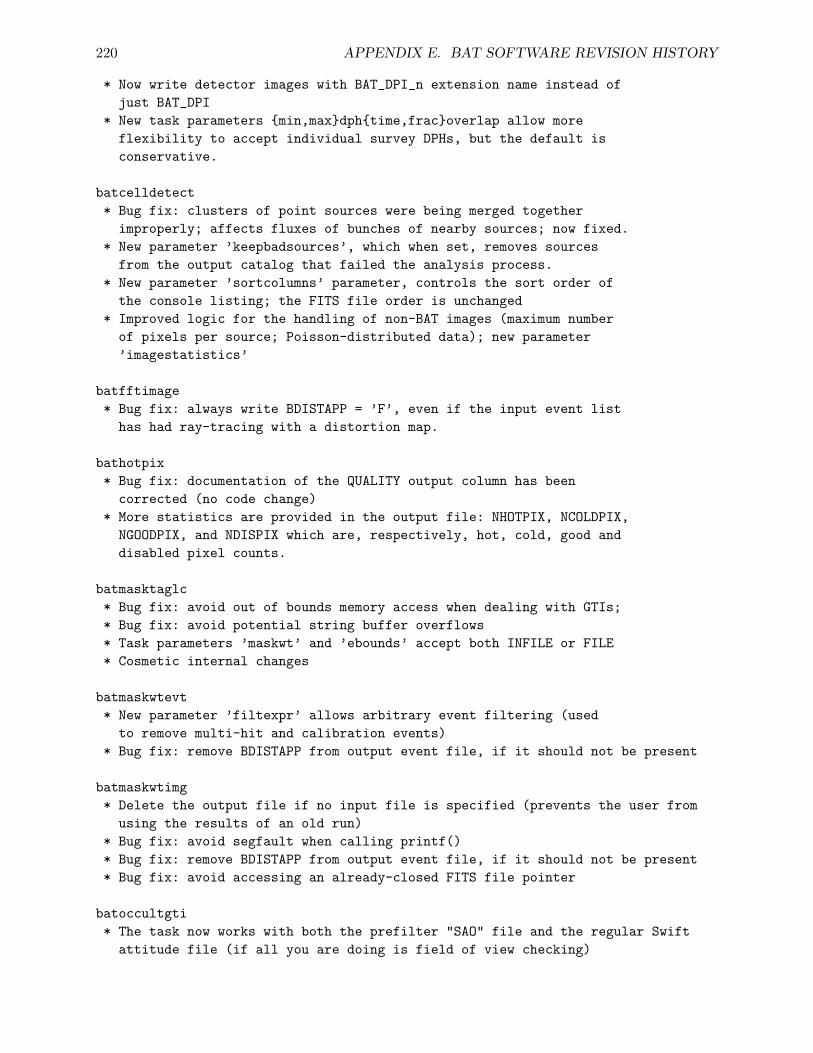
220 APPENDIX E. BAT SOFTWARE REVISION HISTORY
* Now write detector images with BAT_DPI_n extension name instead ofjust BAT_DPI
* New task parameters {min,max}dph{time,frac}overlap allow moreflexibility to accept individual survey DPHs, but the default isconservative.
batcelldetect* Bug fix: clusters of point sources were being merged together
improperly; affects fluxes of bunches of nearby sources; now fixed.* New parameter ’keepbadsources’, which when set, removes sources
from the output catalog that failed the analysis process.* New parameter ’sortcolumns’ parameter, controls the sort order of
the console listing; the FITS file order is unchanged* Improved logic for the handling of non-BAT images (maximum number
of pixels per source; Poisson-distributed data); new parameter’imagestatistics’
batfftimage* Bug fix: always write BDISTAPP = ’F’, even if the input event list
has had ray-tracing with a distortion map.
bathotpix* Bug fix: documentation of the QUALITY output column has been
corrected (no code change)* More statistics are provided in the output file: NHOTPIX, NCOLDPIX,
NGOODPIX, and NDISPIX which are, respectively, hot, cold, good anddisabled pixel counts.
batmasktaglc* Bug fix: avoid out of bounds memory access when dealing with GTIs;* Bug fix: avoid potential string buffer overflows* Task parameters ’maskwt’ and ’ebounds’ accept both INFILE or FILE* Cosmetic internal changes
batmaskwtevt* New parameter ’filtexpr’ allows arbitrary event filtering (used
to remove multi-hit and calibration events)* Bug fix: remove BDISTAPP from output event file, if it should not be present
batmaskwtimg* Delete the output file if no input file is specified (prevents the user from
using the results of an old run)* Bug fix: avoid segfault when calling printf()* Bug fix: remove BDISTAPP from output event file, if it should not be present* Bug fix: avoid accessing an already-closed FITS file pointer
batoccultgti* The task now works with both the prefilter "SAO" file and the regular Swift
attitude file (if all you are doing is field of view checking)
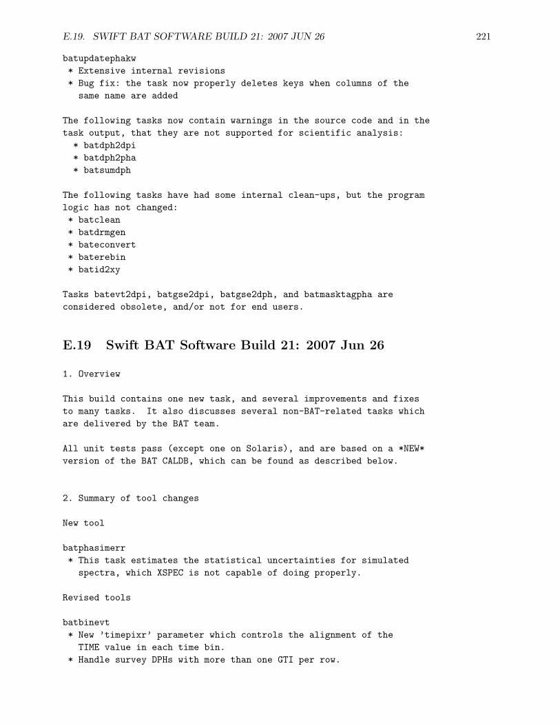
E.19. SWIFT BAT SOFTWARE BUILD 21: 2007 JUN 26 221
batupdatephakw* Extensive internal revisions* Bug fix: the task now properly deletes keys when columns of the
same name are added
The following tasks now contain warnings in the source code and in thetask output, that they are not supported for scientific analysis:
* batdph2dpi* batdph2pha* batsumdph
The following tasks have had some internal clean-ups, but the programlogic has not changed:* batclean* batdrmgen* bateconvert* baterebin* batid2xy
Tasks batevt2dpi, batgse2dpi, batgse2dph, and batmasktagpha areconsidered obsolete, and/or not for end users.
E.19 Swift BAT Software Build 21: 2007 Jun 26
1. Overview
This build contains one new task, and several improvements and fixesto many tasks. It also discusses several non-BAT-related tasks whichare delivered by the BAT team.
All unit tests pass (except one on Solaris), and are based on a *NEW*version of the BAT CALDB, which can be found as described below.
2. Summary of tool changes
New tool
batphasimerr* This task estimates the statistical uncertainties for simulated
spectra, which XSPEC is not capable of doing properly.
Revised tools
batbinevt* New ’timepixr’ parameter which controls the alignment of the
TIME value in each time bin.* Handle survey DPHs with more than one GTI per row.
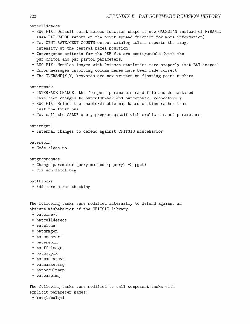
222 APPENDIX E. BAT SOFTWARE REVISION HISTORY
batcelldetect* BUG FIX: Default point spread function shape is now GAUSSIAN instead of PYRAMID
(see BAT CALDB report on the point spread function for more information)* New CENT_RATE/CENT_COUNTS output catalog column reports the image
intensity at the central pixel position.* Convergence criteria for the PSF fit are configurable (with the
psf_chitol and psf_partol parameters)* BUG FIX: Handles images with Poisson statistics more properly (not BAT images)* Error messages involving column names have been made correct* The OVERSMP{X,Y} keywords are now written as floating point numbers
batdetmask* INTERFACE CHANGE: the "output" parameters caldbfile and detmaskused
have been changed to outcaldbmask and outdetmask, respectively.* BUG FIX: Select the enable/disable map based on time rather than
just the first one.* Now call the CALDB query program quzcif with explicit named parameters
batdrmgen* Internal changes to defend against CFITSIO misbehavior
baterebin* Code clean up
batgrbproduct* Change parameter query method (pquery2 -> pget)* Fix non-fatal bug
battblocks* Add more error checking
The following tasks were modified internally to defend against anobscure misbehavior of the CFITSIO library.* batbinevt* batcelldetect* batclean* batdrmgen* bateconvert* baterebin* batfftimage* bathotpix* batmaskwtevt* batmaskwtimg* batoccultmap* batwarpimg
The following tasks were modified to call component tasks withexplicit parameter names:* batglobalgti

E.19. SWIFT BAT SOFTWARE BUILD 21: 2007 JUN 26 223
* batgrbproduct* batoccultgti* batphasyserr
Tasks batevt2dpi, batgse2dpi, batgse2dph, and batmasktagpha areconsidered obsolete, and/or not for end users.

224 APPENDIX E. BAT SOFTWARE REVISION HISTORY


![Cosmological Evolution of Blazars: new findings from the Swift/BAT and Fermi/LAT surveys M. Ajello [KIPAC/SLAC] L. Costamante, R. Sambruna, N. Gehrels,](https://img.pdfslide.net/doc/110x75/56649d4d5503460f94a2c4fc/cosmological-evolution-of-blazars-new-findings-from-the-swiftbat-and-fermilat.jpg)


![DETECTED BY SWIFT/BAT. arXiv:2012.14849v1 [astro-ph.HE] 29](https://img.pdfslide.net/doc/110x75/6252cf3738493479db797ac9/detected-by-swiftbat-arxiv201214849v1-astro-phhe-29-.jpg)