Embed Size (px)
Citation preview
Bi-Level Technologies
From the SelectedWorks of Ron D. Katznelson
May 3, 2004
The Technical Requirements For MultichannelQAM RF ModulatorsRon D Katznelson
Available at: https://works.bepress.com/rkatznelson/4/
NCTA Technical Proceedings, New Orleans, May 3, 2004 (revised)
THE TECHNICAL REQUIREMENTS FOR MULTICHANNEL QAM RF MODULATORS
By Ron D. Katznelson, Ph.D. CTO, Broadband Innovations, Inc., San Diego CA
ABSTRACT
This paper addresses the technical requirements and implications for multichannel QAM RF modulators and upconverters and the factors that affect their proposed RF specifications. RF output power levels per channel, adjacent channel noise and broadband noise levels of such a class of multichannel modulators will be discussed. A spectral noise specification mask that is equivalent to that obtained from a combination of multiple identical masks of a standard single channel noise specifications based on power addition will be presented. The power back-off required for maintaining the proposed distortion mask levels as a function of the number of adjacent channels supported by these devices will be presented. A proposed multichannel downstream RF specification standard based on these results will be presented for consideration for a new DOCSIS™ class of high-density RF modulators.
1 Introduction The advent of new digital services such as Cable IP Telephony, Video On Demand (VOD) and other Interactive TV applications places further demands on HFC’s digital spectrum and, in particular, the ability to increase the number of Narrowcast channel modulators deployed in head-ends and hubs. In an effort to save scarce rack space and costs per channel, the cable industry is well on its way on deploying downstream RF modulator devices that incorporate dual adjacent channel QAM signals at a single RF output port. Prototypes having four contiguous channels per RF output port have also been introduced. However, the technical requirements for such multichannel modulators have not received wide scrutiny or published analysis. The following sections will address these matters. Since RF specifications for single QAM channel devices are contained in the DOCSIS RF Interface specifications [1] (“DOCSIS RFI”), these specifications will form a basis for deriving proposed requirements for the multichannel devices. In what follows, it will be shown that
even for the configuration contemplated currently in the specifications for the single channel case, the current DOCSIS RFI is in need of some basic revisions, as it permits excessive spurious accumulation. Subsequently, assuming these basic revisions, we turn to the multichannel case. The basic premise underlying the construction of the proposed noise and spurious specifications for N contiguous channels is that the resulting composite noise performance be no worse than that obtained by combining the allowed noise degradations from N single channel devices that are compliant with the current DOCSIS RFI for a single channel. In the second part of this paper, the required power levels from such multichannel QAM modulators are addressed.
2 Noise and Modulated Distortion Specifications
The current DOCSIS RFI specifications for a single channel are contained in its Table 6-16 under various categories. In what follows, general specification requirements that in this author’s view should be modified even for a single channel operation are addressed and the appropriate changes to account for multichannel operation are subsequently provided.
2.1 In-band (In-channel) Noise and Spurious DOCSIS RFI entries for this category are given in Table 6-16 as follows:
Total Discrete Spurious Inband (fC ±3 MHz)
< -57dBc
Inband Spurious and Noise (fC ± 3 MHz)
< -48 dBc; where channel spurious and noise includes all discrete spurious, noise, carrier leakage, clock lines, synthesizer products, and other undesired transmitter products. Noise within ± 50 kHz of the carrier is excluded.
1
Unfortunately, both items specified above cannot be measured in practice without actually disabling the QAM modulation. Because much of the in-band noise, (direct spurious, aliased spurious and distortion components) is a result of the actual modulated signal activity, a “clean bill of health” on these unmodulated measures is mostly irrelevant as an indicator for actual In-Channel performance. Rather, In-channel noise degradations are best measured with QAM modulation turned on. Moreover, in testing DOCSIS QAM sources for In-Channel downstream QAM compliance with ITU-T J.83 standard [2], CableLabs’ Acceptance Test Plan calls for evaluating and measuring I/Q Phase Offset, I/Q Crosstalk, I/Q Amplitude Imbalance and I/Q Timing Skew1 [3]. It is generally recognized that, in of themselves, none of these attributes including the two In-Channel DOCSIS RFI specifications in the table above, can predict alone the overall In-Channel performance of the QAM transmitter. While careful characterization of each of these individual attributes may be of interest in diagnosing a particular deficient design that may have otherwise shown to fail an overall QAM link performance, they do not provide an efficient overall single measure for satisfactory In-Channel performance. Furthermore, the proof of compliance with each (rather arbitrary) specification value of these attributes is time consuming and expensive, particularly for multichannel devices, wherein each channel in the group would have to be so tested. It is for that reason that the industry embraced the Modulation Error Ratio (MER) measure as the operative criteria that encompasses all the In-Channel attributes in one relevant measure (see, for example, the tutorial in [4]). Degradations in each of these In-Channel attributes will degrade the MER and the amount of such degradation in dB is essentially the ultimate relevant criteria for QAM source performance. In fact, the current DOCSIS RFI already makes use of MER measures in the upstream channel specifications in its Section 6.2.21.3. MER measures are obtained by measuring the power of the errors in received symbols relative to
the average power of the symbols. For complex representations of the QAM symbols given by Zk , the MER is given by
1 See Section 2.1.4 CMTS ITU-T J.83 Annex B Compliance (Except Interleaving) (PHY-04.1) of the DOCSIS ATP [3]
−=
∑∑
=
=N
k kk
N
k k
ZV
ZMER E
12
12
||
||
where Vk represents the received complex symbols corrupted by noise and other degradations and where E denotes the statistical expectation over the noise in the random variables Vk and over the ensemble of sequences, each of N consecutive symbols. Because all In-channel degradations are exhibited in the deviations of Vk from the reference constellation points Zk, we propose that regardless of the number of channels in the device, In-Channel specifications in the DOCSIS RFI for downstream channels be replaced by a single MER specification. The MER value to adopt for such specification is that which would result from the currently permitted degradation factors found in the DOCSIS RFI. Factors we consider as affecting the MER that are already specified directly or indirectly in the DOCSIS RFI are: (a) Inband discrete and other spurious and
noise. (b) Phase Noise. (c) I/Q Phase Offset, I/Q Crosstalk, I/Q
Amplitude Imbalance and I/Q Timing Skew. Item (a) above is specified at -48 dBc in the current DOCSIS RFI and as such, it is one component that would contribute to the overall composite MER. To be more precise, only the portion of that noise that is filtered by the demodulator’s Root-Nyquist filter and added to the symbols would contribute to the MER and if we assume that the In-Channel spurious and noise is spectrally uniformly distributed over the channel, the fraction of such noise power contributing to the MER is 1 where )1/( α+ α is the Nyquist excess bandwidth factor used over the QAM channel. That means that the In-Channel noise contribution to the MER is given by:
5-10/4810/
1 10 1.41512.1
101
10×==
α+=
−−−
SNR
nMER
2
Corresponding to an MER of approximately 48.5 dB. Similarly, because the I and Q symbol components are assumed to be statistically uncorrelated, the I/Q Crosstalk limit of –50 dB specified by ITU-T-J.83 is another component that would contribute as is to the overall composite MER. The other factors are addressed below:
2.1.1 Phase Noise Effects on MER While we do not propose to replace, substitute or modify DOCSIS’ phase noise requirements, we do need to account for the effect of the permitted DOCSIS RFI phase noise on MER. DOCSIS RFI specifies the permitted phase noise levels in its Table 6-16 as follows:
Frequency Offset Band Double Sided
Integrated Noise Power
Band 1 1 kHz - 10 kHz: -33 dBc Band 2 10 kHz - 50 kHz: -51 dBc Band 3 50 kHz - 3 MHz: -51 dBc
By its very nature, the lack of a specific functional dependence on offset frequency precludes this type of integrated phase noise specification from uniquely predicting the effect on MER. However, under certain assumptions discussed below, reliable realistic estimates can be obtained. The dependence of MER on Phase Noise statistics is analytically treated in detail elsewhere [5], wherein results were derived for MER measuring systems that computationally derive parameter estimates that account for a linear phase trajectory, as expected in ideal modulation sources having no phase noise. It is shown in [5] that the contribution to measured MER from a source having a stationary phase noise with zero mean is designated by and is given by
)(tϕ
ϕMER
∫ τττ−τ−τ−−=
=
ϕϕϕϕ
−ϕ
T
dRTTTT
R
MER
0
24
1
)()]()([4)0(
(1)
where T is the duration of the observation period having consecutive symbols (often called ‘Result Length’) assumed to be large compared to the symbol time TS and )]()([)( ttER ϕτ+ϕ=τϕϕ is
the autocorrelation function of the phase noise that can be obtained from the two sided phase noise spectral density )(ωϕϕS
(ω∫+∞
∞−ϕϕS
by the inverse Fourier transform:
)( ≅ωϕS
MER −ϕ
1
ϕϕ (R
(2) )2/())( πω=τ τωϕϕ deR i
It is shown that for practical purposes, a relatively tight upper bound for can be obtained by using values of the integrated phase noise over frequency offsets that exhibit an inverse square density decline in frequency. Such square law spectral density decline is exhibited by the Lorentzian density, for which the single sided noise power density at the offset frequencies of interest can be approximated by
ϕMER
(3) 20 )()0(
ω−ω
βϕϕR ;
where 0ω is the carrier frequency and βϕϕ )0(R is a constant that can be determined by integrating Equation 3 over the frequency band of interest and equating it to a specified (or measured) integrated phase noise value in that band. It is shown in [5] that for such Lorentzian approximation of the phase noise spectral density, the approximate value so derived is given by
(4) TR β≈ ϕϕ )0(152
It is generally observed that in the DOCSIS phase noise Band 2 (10-50 kHz) the spectral density is dominated by a decline in accordance with Equation (3). By integrating Equation 3 over the 10-50 kHz range and equating the dB result to –51 dBc, the value of is calculated to be 1.96 sec
β)0-1. For a typical MER measurement
condition, a result length of 1024 symbols is selected and at a symbol rate of 5.3 Msps, the observation record time is 193 microseconds. Inserting these values in Equation 4 and expressing it in dB, we obtain
3
(5)
dB 43
])0(152[log10)log(10
MERLimit Noise Phase DOCSIS
10
=
=β−≈
=
ϕϕϕ TRMER
While this result was based only on the data of DOCSIS’ phase noise Band 2, it includes effects from all other bands assuming the behavior depicted in Equation (3) is also present in the other bands. In reality, however, at lower offset frequencies, the phase noise profile is slightly steeper than a square law, although such lower frequency phase noise deviations are mostly tracked out and thus actual results are likely to be only slightly worse than that derived in Equation 5. Moreover, this limit must be used with considerable judgment, as it depends on the observation period T. Nevertheless, for the purposes of this paper, we shall use the 43 dB result.
2.1.2 I/Q Phase Offset and Amplitude Imbalance effects on MER
We now account for the effect of the permitted DOCSIS RFI I/Q Phase Offset and Amplitude Imbalance on MER. The dependence of MER on such factors is analytically treated in detail in [5], where results were derived for a composite degradation of QAM modulators’ deviation from ideal phase quadrature and I/Q gain balance. It was obtained by assuming that the MER measuring instrument finds the regular undistorted reference constellation that minimizes the mean square errors of the distorted received symbols over the entire reference constellation. For distorted signals having small deviations from the ideal constellation, it is given by
(6) 2
)cos()21(1 21 θδ−−
≈−DMER
where θ is the full axis-to-axis angular deviation from precise phase quadrature and where the I/Q gain imbalance in dB is defined by as follows: δ
(7)
−+
=δδ
11log20 ImbalanceGain I/Q 10
For the worst-case deviations permitted by ITU-T-J.83, one obtains for θ =10 an MERD of 41.18 dB and for δ =0.00289 (a gain imbalance of 0.05 dB) a value of 50.8 dB is obtained for MERD . When both degradations exist simultaneously, the worst-case composite MERD is calculated to be 40.73 dB.
2.1.3 Other MER degradation Factors Other factors that generally may affect the observed MER on a given channel within a multichannel setting containing DOCSIS compliant QAM channels are as follows:
2.1.3.1 Nonlinear modulated distortions from adjacent channels
These permitted modulated distortion and noise components that invade the test channel arise out of Band I and II (treated in Section 2.2). Because the test channel demodulator’s Nyquist filter provides appreciable roll-off attenuation within the band-edge where the power density of these components is the highest, these weighted components from two adjacent channels are unlikely to exceed –60 dBc and are therefore negligible for our analysis. However, this observation is by no means a reason to forgo MER measurements in the presence of these adjacent channels, as their nonlinear interaction with other channels within the QAM device generates additional in-channel intermodulation components that are not accounted for above and that must be included in the evaluation.
2.1.3.2 Linear modulator distortions including frequency response and group delay variations
To that end, ITU-T-J.83 specifies a maximum baseband frequency response ripple or channel slope in the Nyquist band of 0.4 dB peak-to-peak and a group delay not to exceed 0.1TS 2. The DOCSIS ATP3 provides for an "expected" spectral flatness of +0.3/-0.5 dB at the Nyquist flat-band edge, although it is not an express requirement of 2 See Figure A8 in J.83, wherein the ripple requirement is set for Annex A, which is included in the Euro-DOCSIS. However, none of the ripple or group delay requirements were incorporated in Annex B. 3 See Section 2.1.6 "CMTS Output Spectrum (PHY-06.1)" of the DOCSIS ATP [3]
4
the DOCSIS RFI. Uncorrected, or unequalized, these linear distortions can degrade the composite MER by a few dB. For example, [5] provides an analytical closed form derivation showing that a channel with no group delay distortion but with a frequency response linear magnitude slope having channel transfer function magnitude of 1 on one Nyquist frequency channel edge and ε−1 on the other, (exhibiting a slope of
dB per Nyquist channel width), will exhibit an unequalized MER given by
)]1/()1[(log20 ε−ε+10
ε+
(8)
π−α−α−ε=−
221 81
21
31
SMER
where is the raised cosine excess bandwidth factor used over the QAM channel. With a 0.4 dB slope across the Nyquist band of a 256 QAM channel ( ), one obtains an unequalized MER of 38.3 dB. However, because typical specifications of MER measuring instruments is also 0.4 dB PTP, depending on the direction of the slope, actual measured MER may be as low as 32 dB (corresponding to 0.8 dB composite slope across the Nyquist band) or as high as the residual MER of the instrument (corresponding to 0 dB composite slope). Fortunately, unlike the other factors described in the previous sections that cannot be corrected by the decoders’ adaptive equalization, the linear distortion effects of the magnitudes permitted above can be virtually eliminated by the decoder’s adaptive equalizer with negligible loss of noise margin associated with the equalizer’s deviation from nominal response. It is for this reason that the MER measures recommended herein must be performed with adaptive equalization engaged. The practice of characterizing QAM RF modulators using unequalized MER has recently received some industry acceptance because it has the advantage of providing a single measure for the composite degradations due to channel frequency response and group delay variations. However, this measure includes the test measurement receiver distortions that are difficult to separate from the overall result. Because the frequency response specifications of MER test receivers are of the same magnitude as those permitted for QAM modulators and because instrument distortion directions is unpredictable, these measures can
often be non repeatable among different instruments unless a specialized calibration step is taken. One such calibration process using a “golden” QAM reference source is described in Section 2.1.26.3 of the DOCSIS ATP.[3]
α
2.1.3.3 MER measurement instrument residual MER and noise floor.
This factor relates to the dynamic range limitation of the measurement receiver and demodulator itself. The residual MER is the value measured by the instrument when feeding it with an ideal QAM source. Although an ideal QAM source does not exist, MER instrument manufacturers specify their product’s residual MER in the 40-43 dB range, depending on product. Actual values normally encountered are in the range of 46-52 dB.
2.1.3.4 MER measurement instrument’s linear and nonlinear degradations due to adjacent channels 12.0=α
This factor is not insignificant because, as we note in Section 2.1.3.1, multichannel QAM devices are best evaluated with all their channels ‘on’. Unfortunately, the adjacent channel filtering and the dynamic range limitation of the measurement receiver cause some MER degradations. Experience with multiple independent single channel modulators has shown that these degradations exhibited by high-end MER measurement devices can reach 0.5-0.7 dB when MER in the range of 43 dB are measured.
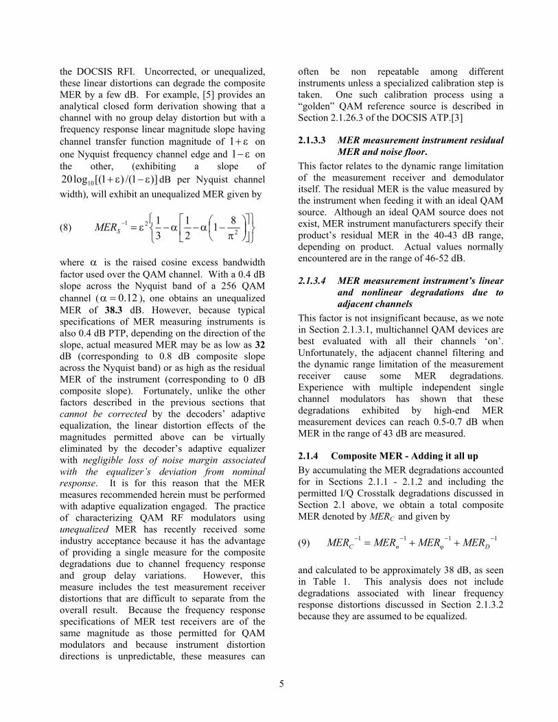
2.1.4 Composite MER - Adding it all up By accumulating the MER degradations accounted for in Sections 2.1.1 - 2.1.2 and including the permitted I/Q Crosstalk degradations discussed in Section 2.1 above, we obtain a total composite MER denoted by MERC and given by (9) 1111 −−
ϕ−− ++= DnC MERMERMERMER
and calculated to be approximately 38 dB, as seen in Table 1. This analysis does not include degradations associated with linear frequency response distortions discussed in Section 2.1.3.2 because they are assumed to be equalized.
5
Degradation Factor dB Relative Power
In-band Spurious and Noise -48.50 1.41E-05Phase Noise -43.00 5.01E-05
I/Q Phase error & Gain Imbalance -40.73 8.45E-05I/Q Crosstalk -50.00 1.00E-05
Total Relative Power 1.59E-04Composite MER 37.99
Table 1. Accumulation of worst case permitted DOCSIS degradations forming a composite MER.
However, it should be noted that in today’s full digital implementation of quadrature modulation, I/Q Phase Offset, I/Q Crosstalk, I/Q Amplitude Imbalance and I/Q Timing Skew errors are virtually non-existent. On the other hand, Table 1 does not include the MER measurement device’s residual MER floor as discussed in Sections 2.1.3.3 and 2.1.3.4. Therefore, it would be reasonable to expect that digitally implemented QAM modulators that otherwise just meet the current DOCSIS RFI requirements and that are measured with a typical laboratory MER instrument having a 45 dB residual MER, would exhibit the MER value shown in Table 2 below.
Degradation Factor dB Relative Power
In-band Spurious and Noise -48.50 1.41E-05Phase Noise -43.00 5.01E-05
Meas. Instrmnt. Residual MER -45.00 3.16E-05Total Relative Power 9.59E-05
Composite MER 40.18 Table 2 Accumulation of residual MER and permitted DOCSIS degradations except I/Q degradations. This means that even without any quadrature distortions, a single channel digital QAM source that just meets the current DOCSIS RFI requirements cannot exhibit an MER higher than 40.2 dB. It is for this reason that, in summary, we propose a single In-band noise and spurious specification to replace those in the current DOCSIS RFI as follows: In-channel discrete and other Spurious and Noise
40 dB MER, using equalized demodulator with 1024 symbols Result Length
2.2 Adjacent Channels In order to provide the DOCSIS RFI equivalent noise mask for multichannel QAM RF modulators, we now account for accumulation effect of the permitted noise levels from multiple contiguous channels.
-15 -9 -3 3 9 15
Frequency Offset from Center Channel (MHz)
Power Density (10dB/Div)
Linear filter residual skirtLinear filter residual skirt
750 KHz, Band I
5.25 MHz
Band II
5.25 MHz
Band II6 MHz
Band III6 MHz
Band III
Third Order Regrowth Fifth Order
Regrowth & Noise
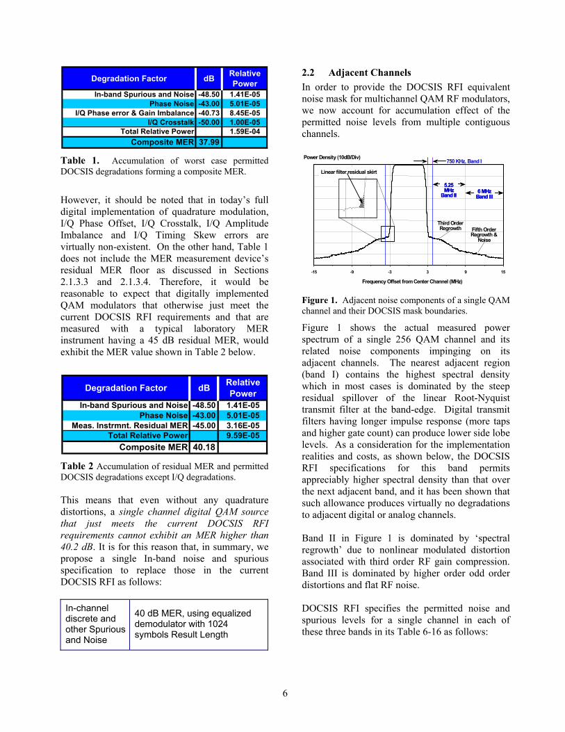
Figure 1. Adjacent noise components of a single QAM channel and their DOCSIS mask boundaries.
Figure 1 shows the actual measured power spectrum of a single 256 QAM channel and its related noise components impinging on its adjacent channels. The nearest adjacent region (band I) contains the highest spectral density which in most cases is dominated by the steep residual spillover of the linear Root-Nyquist transmit filter at the band-edge. Digital transmit filters having longer impulse response (more taps and higher gate count) can produce lower side lobe levels. As a consideration for the implementation realities and costs, as shown below, the DOCSIS RFI specifications for this band permits appreciably higher spectral density than that over the next adjacent band, and it has been shown that such allowance produces virtually no degradations to adjacent digital or analog channels. Band II in Figure 1 is dominated by ‘spectral regrowth’ due to nonlinear modulated distortion associated with third order RF gain compression. Band III is dominated by higher order odd order distortions and flat RF noise. DOCSIS RFI specifies the permitted noise and spurious levels for a single channel in each of these three bands in its Table 6-16 as follows:
6
Adjacent channel (fC ± 3.0 MHz) to (fC ± 3.75 MHz)
< -58 dBc in 750 kHz
Adjacent channel (fC ± 3.75 MHz) to (fC ± 9 MHz)
< -62 dBc, in 5.25 MHz, excluding up to 3 spurs, each of which must be < -60 dBc when measured in a 10 kHz band
Next adjacent channel (fC ± 9 MHz) to (fC ± 15 MHz)
Less than the greater of -65 dBc or -12dBmV in 6MHz, excluding up to threediscrete spurs. The total power in thespurs must be < -60 dBc when each ismeasured with 10 kHz bandwidth.
Figure 2 shows graphically a summary of these specifications wherein, for clarity, the mask does not include the –12 dBmV alternatives or the specification language on –60 dBc discrete spurs.
Desiredchannelsignal
Power in6 MHz isthe 0 dB
Reference 'Other Channels' -Broadband noise
-12 dBmV(- 62 dBc to - 73 dBc)
Band II- 62 dBc
PowerSpectralDensity
Frequency
Band I- 58 dBc
Band III- 65 dBc
Figure 2. DOCSIS spectral mask for a single QAM channel.
2.2.1 Channels Adjacent to Multichannel Sources
Adjacent channel noise specifications are best provided in dBc, as argued below. For multiple channel operation, we adopt an underlying construction of the proposed noise and spurious specifications for N contiguous channels by combining the allowed noise degradations from N single channel devices that are compliant with the current DOCSIS RFI for a single channel. As discussed below, we adopt the appropriately conservative requirement that ignores the absolute –12 dBmV relaxing alternatives and thus all specifications are in dBc including the Other Channels’ specification that is assumed to be –73 dBc with an output power level of 61 dBmV for a single channel. We denote by N the number of channels in the QAM group and obtain the following noise and spurious specifications in dBc for in the three bands: 2≥N
Band I: (Channel Group edge) to (Channel Group Edge +(-) 0.75 MHz):
−+
+<
−−−
•1073
1065
1058
10 10)2(10675.010log10 N
dBc in 750 kHz Band II: (Channel Group edge +(-) 0.75 MHz) to (Channel Group Edge +(-) 6 MHz) :
−+
+<
−−−
•1073
1065
1062
10 10)2(10625.510log10 N
dBc in 5.25 MHz. Band III: (Channel Group edge +(-) 6 MHz) to (Channel Group Edge +(-) 12 MHz) :
{ }10/7310/65 10)1(10log10 −−•−+< N
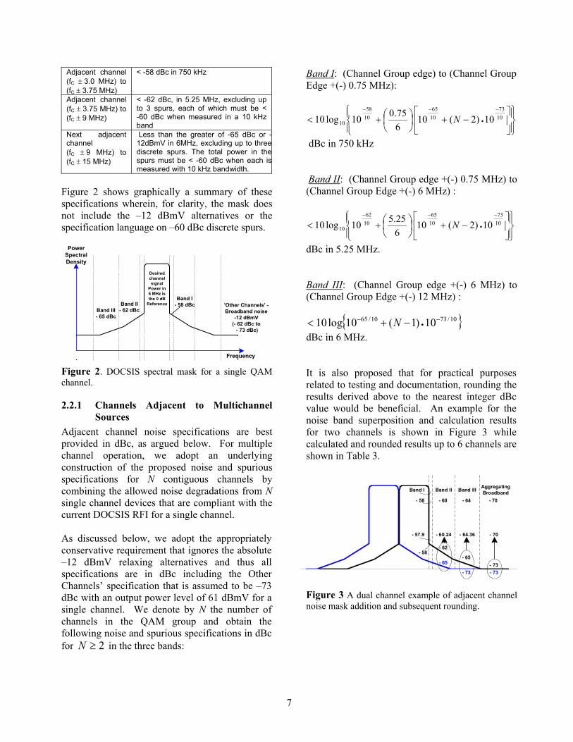
dBc in 6 MHz. It is also proposed that for practical purposes related to testing and documentation, rounding the results derived above to the nearest integer dBc value would be beneficial. An example for the noise band superposition and calculation results for two channels is shown in Figure 3 while calculated and rounded results up to 6 channels are shown in Table 3.
- 65
- 62- 58
- 65- 73
- 60.24 - 64.36 - 70
- 73 - 73
- 60 - 64 - 70
- 57.9
- 58
Band II Band III AggregatingBroadbandBand I
Figure 3 A dual channel example of adjacent channel noise mask addition and subsequent rounding.
7
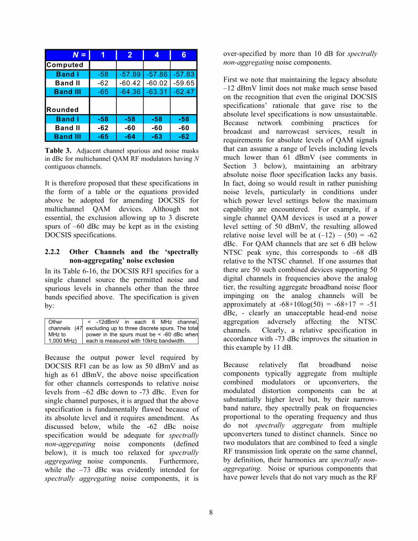
N = 1 2 4 6Computed
Band I -58 -57.89 -57.86 -57.83Band II -62 -60.42 -60.02 -59.65Band III -65 -64.36 -63.31 -62.47
RoundedBand I -58 -58 -58 -58Band II -62 -60 -60 -60Band III -65 -64 -63 -62
Table 3. Adjacent channel spurious and noise masks in dBc for multichannel QAM RF modulators having N contiguous channels.
It is therefore proposed that these specifications in the form of a table or the equations provided above be adopted for amending DOCSIS for multichannel QAM devices. Although not essential, the exclusion allowing up to 3 discrete spurs of –60 dBc may be kept as in the existing DOCSIS specifications.
2.2.2 Other Channels and the ‘spectrally non-aggregating’ noise exclusion
In its Table 6-16, the DOCSIS RFI specifies for a single channel source the permitted noise and spurious levels in channels other than the three bands specified above. The specification is given by:
Other channels (47MHz to 1,000 MHz)
< -12dBmV in each 6 MHz channel,excluding up to three discrete spurs. The totalpower in the spurs must be < -60 dBc wheneach is measured with 10kHz bandwidth.
Because the output power level required by DOCSIS RFI can be as low as 50 dBmV and as high as 61 dBmV, the above noise specification for other channels corresponds to relative noise levels from –62 dBc down to -73 dBc. Even for single channel purposes, it is argued that the above specification is fundamentally flawed because of its absolute level and it requires amendment. As discussed below, while the -62 dBc noise specification would be adequate for spectrally non-aggregating noise components (defined below), it is much too relaxed for spectrally aggregating noise components. Furthermore, while the –73 dBc was evidently intended for spectrally aggregating noise components, it is
over-specified by more than 10 dB for spectrally non-aggregating noise components. First we note that maintaining the legacy absolute –12 dBmV limit does not make much sense based on the recognition that even the original DOCSIS specifications’ rationale that gave rise to the absolute level specifications is now unsustainable. Because network combining practices for broadcast and narrowcast services, result in requirements for absolute levels of QAM signals that can assume a range of levels including levels much lower than 61 dBmV (see comments in Section 3 below), maintaining an arbitrary absolute noise floor specification lacks any basis. In fact, doing so would result in rather punishing noise levels, particularly in conditions under which power level settings below the maximum capability are encountered. For example, if a single channel QAM devices is used at a power level setting of 50 dBmV, the resulting allowed relative noise level will be at (–12) – (50) = -62 dBc. For QAM channels that are set 6 dB below NTSC peak sync, this corresponds to –68 dB relative to the NTSC channel. If one assumes that there are 50 such combined devices supporting 50 digital channels in frequencies above the analog tier, the resulting aggregate broadband noise floor impinging on the analog channels will be approximately at -68+10log(50) = -68+17 = -51 dBc, - clearly an unacceptable head-end noise aggregation adversely affecting the NTSC channels. Clearly, a relative specification in accordance with -73 dBc improves the situation in this example by 11 dB. Because relatively flat broadband noise components typically aggregate from multiple combined modulators or upconverters, the modulated distortion components can be at substantially higher level but, by their narrow-band nature, they spectrally peak on frequencies proportional to the operating frequency and thus do not spectrally aggregate from multiple upconverters tuned to distinct channels. Since no two modulators that are combined to feed a single RF transmission link operate on the same channel, by definition, their harmonics are spectrally non-aggregating. Noise or spurious components that have power levels that do not vary much as the RF
8
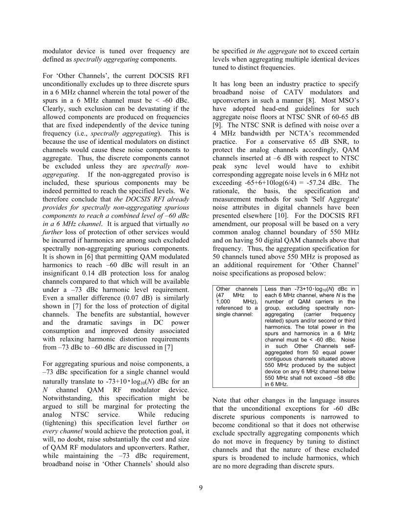
modulator device is tuned over frequency are defined as spectrally aggregating components. For ‘Other Channels’, the current DOCSIS RFI unconditionally excludes up to three discrete spurs in a 6 MHz channel wherein the total power of the spurs in a 6 MHz channel must be < -60 dBc. Clearly, such exclusion can be devastating if the allowed components are produced on frequencies that are fixed independently of the device tuning frequency (i.e., spectrally aggregating). This is because the use of identical modulators on distinct channels would cause these noise components to aggregate. Thus, the discrete components cannot be excluded unless they are spectrally non-aggregating. If the non-aggregated proviso is included, these spurious components may be indeed permitted to reach the specified levels. We therefore conclude that the DOCSIS RFI already provides for spectrally non-aggregating spurious components to reach a combined level of –60 dBc in a 6 MHz channel. It is argued that virtually no further loss of protection of other services would be incurred if harmonics are among such excluded spectrally non-aggregating spurious components. It is shown in [6] that permitting QAM modulated harmonics to reach –60 dBc will result in an insignificant 0.14 dB protection loss for analog channels compared to that which will be available under a –73 dBc harmonic level requirement. Even a smaller difference (0.07 dB) is similarly shown in [7] for the loss of protection of digital channels. The benefits are substantial, however and the dramatic savings in DC power consumption and improved density associated with relaxing harmonic distortion requirements from –73 dBc to –60 dBc are discussed in [7] For aggregating spurious and noise components, a –73 dBc specification for a single channel would naturally translate to -73+10٠log10(N) dBc for an N channel QAM RF modulator device. Notwithstanding, this specification might be argued to still be marginal for protecting the analog NTSC service. While reducing (tightening) this specification level further on every channel would achieve the protection goal, it will, no doubt, raise substantially the cost and size of QAM RF modulators and upconverters. Rather, while maintaining the –73 dBc requirement, broadband noise in ‘Other Channels’ should also
be specified in the aggregate not to exceed certain levels when aggregating multiple identical devices tuned to distinct frequencies. It has long been an industry practice to specify broadband noise of CATV modulators and upconverters in such a manner [8]. Most MSO’s have adopted head-end guidelines for such aggregate noise floors at NTSC SNR of 60-65 dB [9]. The NTSC SNR is defined with noise over a 4 MHz bandwidth per NCTA’s recommended practice. For a conservative 65 dB SNR, to protect the analog channels accordingly, QAM channels inserted at –6 dB with respect to NTSC peak sync level would have to exhibit corresponding aggregate noise levels in 6 MHz not exceeding -65+6+10log(6/4) = -57.24 dBc. The rationale, the basis, the specification and measurement methods for such 'Self Aggregate' noise attributes in digital channels have been presented elsewhere [10]. For the DOCSIS RFI amendment, our proposal will be based on a very common analog channel boundary of 550 MHz and on having 50 digital QAM channels above that frequency. Thus, the aggregation specification for 50 channels tuned above 550 MHz is proposed as an additional requirement for ‘Other Channel’ noise specifications as proposed below:
Other channels (47 MHz to 1,000 MHz), referenced to a single channel:
Less than -73+10٠log10(N) dBc in each 6 MHz channel, where N is the number of QAM carriers in the group, excluding spectrally non-aggregating (carrier frequency related) spurs and/or second or third harmonics. The total power in the spurs and harmonics in a 6 MHz channel must be < -60 dBc. Noise in such Other Channels self-aggregated from 50 equal power contiguous channels situated above 550 MHz produced by the subject device on any 6 MHz channel below 550 MHz shall not exceed –58 dBc in 6 MHz.
Note that other changes in the language insures that the unconditional exceptions for -60 dBc discrete spurious components is narrowed to become conditional so that it does not otherwise exclude spectrally aggregating components which do not move in frequency by tuning to distinct channels and that the nature of these excluded spurs is broadened to include harmonics, which are no more degrading than discrete spurs.
9
3 RF Power Levels In adopting standards for the RF power levels of QAM devices that can transmit up to N contiguous channels, we make the following assumptions: (a) The unit may be configured to operate in
fewer than N channels and even in a single channel mode. It should be power efficient in each of the channel setting configurations.
(b) The unit must comply with the multichannel specifications proposed herein including the adjacent channel modulated distortion noise mask.
(c) The output levels per channel supplied by the unit at each channel number configuration should be sufficient for virtually all Narrowcast head-end and hub configurations.
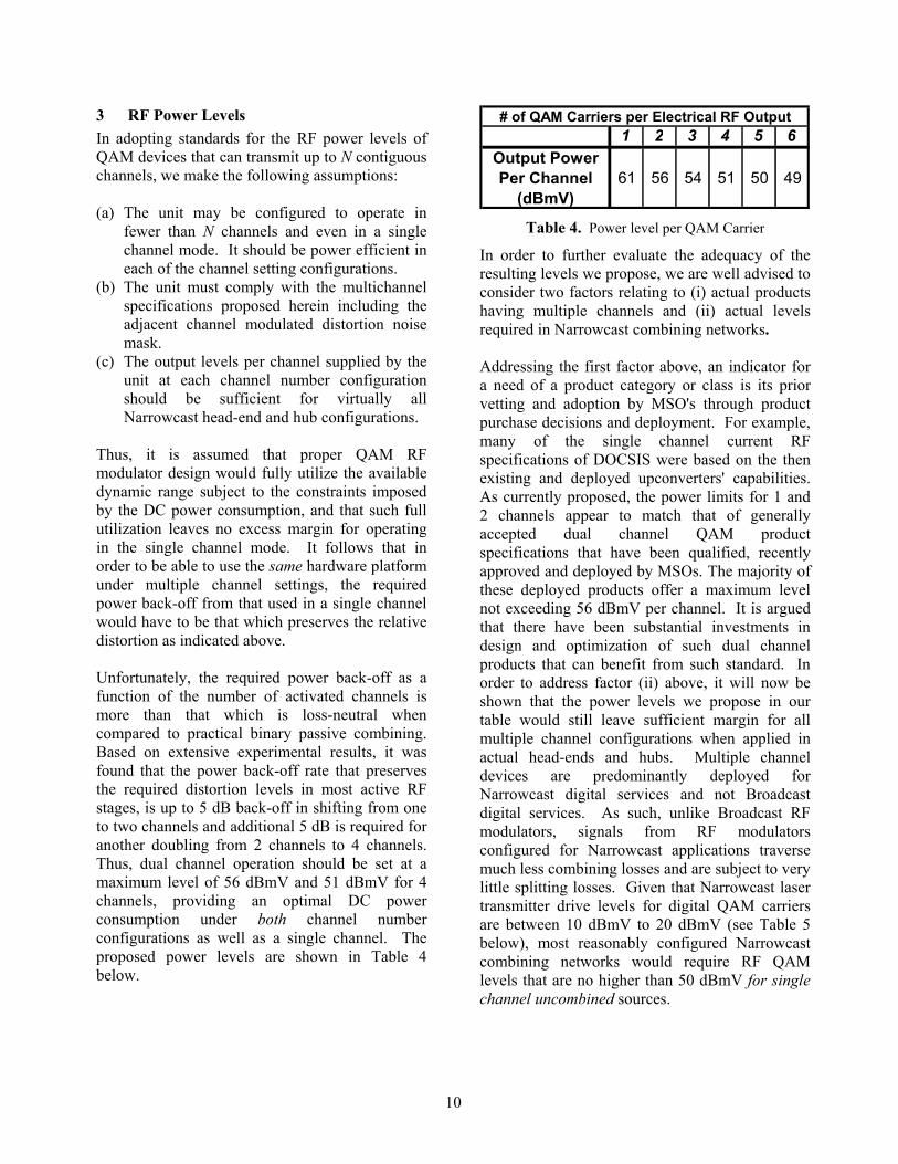
Thus, it is assumed that proper QAM RF modulator design would fully utilize the available dynamic range subject to the constraints imposed by the DC power consumption, and that such full utilization leaves no excess margin for operating in the single channel mode. It follows that in order to be able to use the same hardware platform under multiple channel settings, the required power back-off from that used in a single channel would have to be that which preserves the relative distortion as indicated above. Unfortunately, the required power back-off as a function of the number of activated channels is more than that which is loss-neutral when compared to practical binary passive combining. Based on extensive experimental results, it was found that the power back-off rate that preserves the required distortion levels in most active RF stages, is up to 5 dB back-off in shifting from one to two channels and additional 5 dB is required for another doubling from 2 channels to 4 channels. Thus, dual channel operation should be set at a maximum level of 56 dBmV and 51 dBmV for 4 channels, providing an optimal DC power consumption under both channel number configurations as well as a single channel. The proposed power levels are shown in Table 4 below.
1 2 3 4 5 6Output Power Per Channel
(dBmV)61 56 54 51 50 49
# of QAM Carriers per Electrical RF Output
Table 4. Power level per QAM Carrier
In order to further evaluate the adequacy of the resulting levels we propose, we are well advised to consider two factors relating to (i) actual products having multiple channels and (ii) actual levels required in Narrowcast combining networks. Addressing the first factor above, an indicator for a need of a product category or class is its prior vetting and adoption by MSO's through product purchase decisions and deployment. For example, many of the single channel current RF specifications of DOCSIS were based on the then existing and deployed upconverters' capabilities. As currently proposed, the power limits for 1 and 2 channels appear to match that of generally accepted dual channel QAM product specifications that have been qualified, recently approved and deployed by MSOs. The majority of these deployed products offer a maximum level not exceeding 56 dBmV per channel. It is argued that there have been substantial investments in design and optimization of such dual channel products that can benefit from such standard. In order to address factor (ii) above, it will now be shown that the power levels we propose in our table would still leave sufficient margin for all multiple channel configurations when applied in actual head-ends and hubs. Multiple channel devices are predominantly deployed for Narrowcast digital services and not Broadcast digital services. As such, unlike Broadcast RF modulators, signals from RF modulators configured for Narrowcast applications traverse much less combining losses and are subject to very little splitting losses. Given that Narrowcast laser transmitter drive levels for digital QAM carriers are between 10 dBmV to 20 dBmV (see Table 5 below), most reasonably configured Narrowcast combining networks would require RF QAM levels that are no higher than 50 dBmV for single channel uncombined sources.
10
DFB Laser TX Input level (Per NTSC Carrier)
Input Return Loss
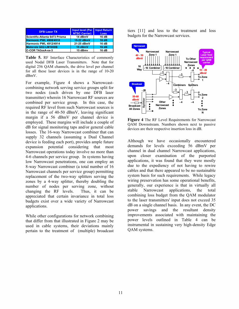
Scientific-Atlanta 6473 Prisma 14 dBmV 16 dBHarmonic PWL 4908/4910 15-22 dBmV 16 dBHarmonic PWL 4912/4914 21-25 dBmV 16 dBMotorola GX2-LM1000B 15 dBmV 16 dBC-COR TA3xxA-xx-3 15 dBmv 16 dB Table 5. RF Interface Characteristics of commonly used Nodal DFB Laser Transmitters. Note that for digital 256 QAM channels, the drive level per channel for all these laser devices is in the range of 10-20 dBmV.
For example, Figure 4 shows a Narrowcast-combining network serving service groups split for two nodes (each driven by one DFB laser transmitter) wherein 16 Narrowcast RF sources are combined per service group. In this case, the required RF level from such Narrowcast sources is in the range of 40-50 dBmV, leaving significant margin if a 56 dBmV per channel device is employed. These margins will include a couple of dB for signal monitoring taps and/or general cable losses. The 16-way Narrowcast combiner that can supply 32 channels (assuming a Dual Channel device is feeding each port), provides ample future expansion potential considering that most Narrowcast operations today involve no more than 4-6 channels per service group. In systems having low Narrowcast penetrations, one can employ an 8-way Narrowcast combiner (a total number of 16 Narrowcast channels per service group) permitting replacement of the two-way splitters serving the zones by a 4-way splitter, thereby doubling the number of nodes per serving zone, without changing the RF levels. Thus, it can be appreciated that certain invariance in total loss budgets exist over a wide variety of Narrowcast applications. While other configurations for network combining that differ from that illustrated in Figure 2 may be used in cable systems, their deviations mainly pertain to the treatment of (multiple) broadcast
tiers [11] and less to the treatment and loss budgets for the Narrowcast services.
Spl
itter
BroadcastAll Zones
Combiner Combiner
Narrowcast Zone 1
To OtherNarrowcast
Zones
To Zone1
To Zone2
To ZoneN
OtherNarrowcast
Zones
Combiners- 4
- 16 - 16
- 28
16Way
- 4
- 3
- 3
- 3- 4
- 4
- 3
Splitters
Narrowcast Zone 1
Broadcast
Narrowcast
TypicalLaser feed
requirementper QAMcarrier
10 - 20dBmV
40 - 50dBmV
55-60dBmV
Figure 4 The RF Level Requirements for Narrowcast QAM Downstream. Numbers shown next to passive devices are their respective insertion loss in dB.
Although we have occasionally encountered demands for levels exceeding 56 dBmV per channel in dual channel Narrowcast applications, upon closer examination of the purported applications, it was found that they were mostly due to the expediency of not having to rewire cables and that there appeared to be no sustainable system basis for such requirements. While legacy wiring preservation has some operational benefits, generally, our experience is that in virtually all stable Narrowcast applications, the total combining loss budget from the QAM modulator to the laser transmitters' input does not exceed 35 dB on a single channel basis. In any event, the DC power savings and the resultant density improvements associated with maintaining the power levels outlined in Table 4 can be instrumental in sustaining very high-density Edge QAM systems.
11
References [1] CableLabs, “DOCSIS Radio Frequency
Interface Specification”, SP-RFIv2.0. Available at http://www.cablemodem.com/downloads/specs/SP-RFIv2.0-I05-040407.pdf
[2] ITU-T Recommendation J.83 Annex B.
“Digital Multi-Programme Systems for Television Sound and Data Services for Cable Distribution”. (April 1997).
[3] CableLabs, “DOCSIS 1.1 & 2.0 RFI
Acceptance Test Plan”, TP-RFI-ATP. Available at http://www.cablemodem.com/downloads/specs/TP-RFI-ATP-I04-030716.pdf .
[4] Gérard Terreault. “QAM Signal
Impairments and Their Effects on MER and BER”. Sunrise Telecom, (2003). Available at http://www.sunrisetelecom.com/broadband/QAM_Impairment_Effects_on_MER_BER_104.pdf
[5] Ron D. Katznelson, “The dependence of
MER on Phase Noise and other Modulator Impairments in QAM Channels”, Submitting to IEEE publication (2004). Available at http://www.broadbandinnovations.com/pubs/frm-pubs.html.
[6] Kirk Ashby, “Impact of Non-Aggregating
Modulated Spurious Signals on Analog Television Channels”. Submission to an Ad-Hoc RF working group for a draft DOCSIS ECR. March, (2004).
[7] Ron D. Katznelson, “A Case for Including
Harmonic Distortion Components in DOCSIS’ RF Specifications for Non Aggregating Spurious Components”. Submission to an Ad-Hoc RF working group for a draft DOCSIS ECR. April (2004). Available at http://www.broadbandinnovations.com/pubs/frm-pubs.html.
[8] See the 65 dB aggregate SNR on the front
page of Motorola’s Commander® 8 modulator specifications at http://broadband.motorola.com/catalog/product_documents/C8M_Commander_Modulator_NTSC.pdf and that of Scientific-Atlanta’s Continuum® modulator at http://www.sciatl.com/customers/Source/750885.pdf
[9] Oleh Sniezko, “Multi-Layer Headend
Combining Network Design for Broadcast, Local and Targeted Services”. NCTA Technical Papers, pp. 300-315, (1997).
[10] S. I. Rubin, A. Basovich, B. Petrovic and
R. D. Katznelson, "Specifying and Measuring Aggregate Broadband Noise of CATV Modulators and Upconverters" SCTE Cable-Tec Expo®, San Antonio, TX, June 5-7, (2002). Available at http://www.broadbandinnovations.com/pubs/frm-pubs.html.
[11] See, for example, the configurations
described by: Jerry K. Thorne, “Using RF Amplifiers to Optimize Headend and Hub Site Isolation”. Quality RF Services, Inc. Available at http://www.atxnetworks.com/WhitePapers/RFAmp_OptIsolation.pdf
Author contact: Ron D. Katznelson Broadband Innovations, Inc. Tel: (858) 395-1440
For downloading any revisions or corrections of this paper go to: http://www.broadbandinnovations.com/pubs/frm-pubs.html
12