Embed Size (px)
Citation preview
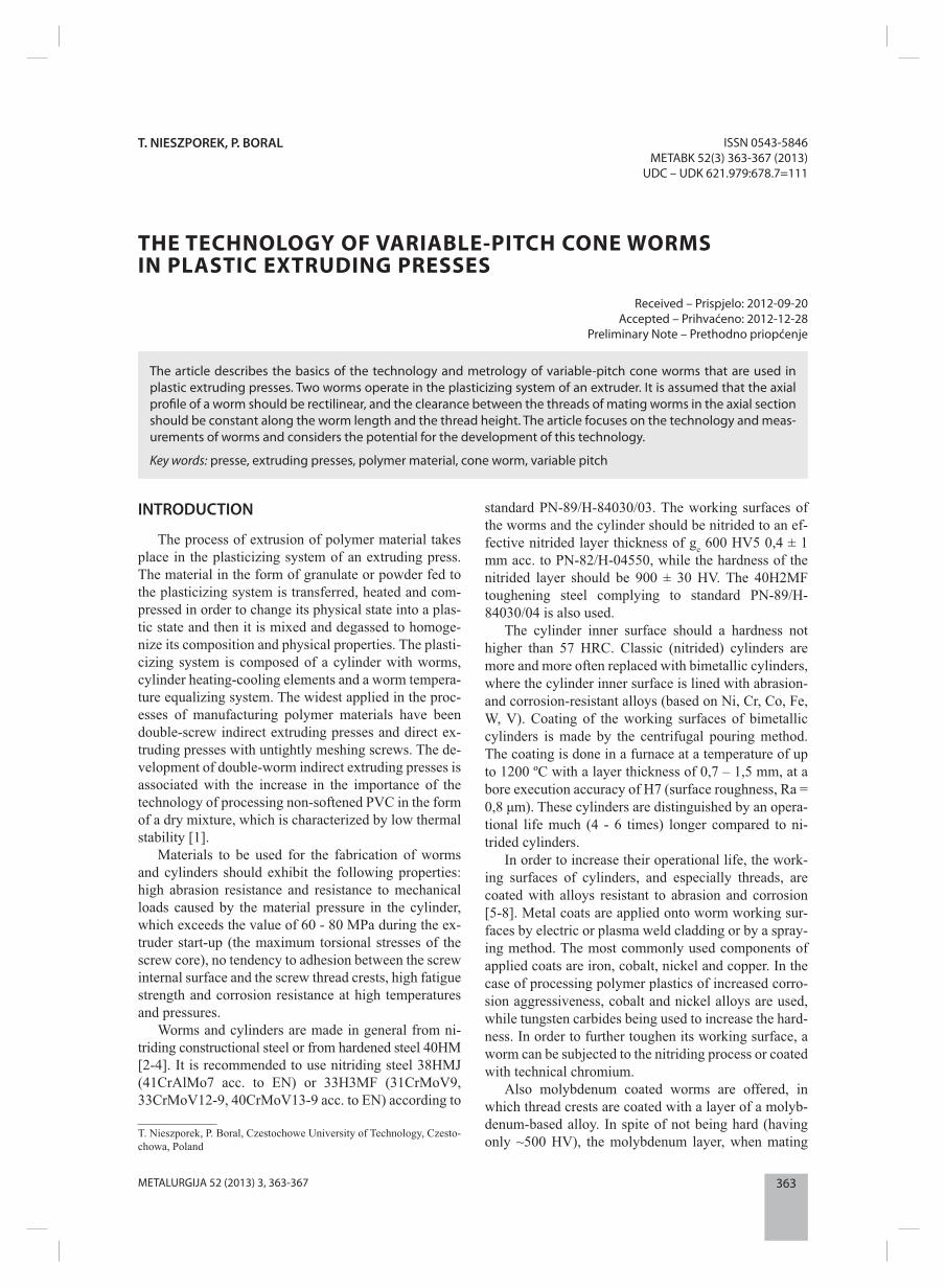
363METALURGIJA 52 (2013) 3, 363-367
T. NIESZPOREK, P. BORAL
THE TECHNOLOGY OF VARIABLE-PITCH CONE WORMS IN PLASTIC EXTRUDING PRESSES
Received – Prispjelo: 2012-09-20Accepted – Prihvaćeno: 2012-12-28
Preliminary Note – Prethodno priopćenje
ISSN 0543-5846METABK 52(3) 363-367 (2013)
UDC – UDK 621.979:678.7=111
T. Nieszporek, P. Boral, Czestochowe University of Technology, Czesto-chowa, Poland
The article describes the basics of the technology and metrology of variable-pitch cone worms that are used in plastic extruding presses. Two worms operate in the plasticizing system of an extruder. It is assumed that the axial profi le of a worm should be rectilinear, and the clearance between the threads of mating worms in the axial section should be constant along the worm length and the thread height. The article focuses on the technology and meas-urements of worms and considers the potential for the development of this technology.
Key words: presse, extruding presses, polymer material, cone worm, variable pitch
INTRODUCTION
The process of extrusion of polymer material takes place in the plasticizing system of an extruding press. The material in the form of granulate or powder fed to the plasticizing system is transferred, heated and com-pressed in order to change its physical state into a plas-tic state and then it is mixed and degassed to homoge-nize its composition and physical properties. The plasti-cizing system is composed of a cylinder with worms, cylinder heating-cooling elements and a worm tempera-ture equalizing system. The widest applied in the proc-esses of manufacturing polymer materials have been double-screw indirect extruding presses and direct ex-truding presses with untightly meshing screws. The de-velopment of double-worm indirect extruding presses is associated with the increase in the importance of the technology of processing non-softened PVC in the form of a dry mixture, which is characterized by low thermal stability [1].
Materials to be used for the fabrication of worms and cylinders should exhibit the following properties: high abrasion resistance and resistance to mechanical loads caused by the material pressure in the cylinder, which exceeds the value of 60 - 80 MPa during the ex-truder start-up (the maximum torsional stresses of the screw core), no tendency to adhesion between the screw internal surface and the screw thread crests, high fatigue strength and corrosion resistance at high temperatures and pressures.
Worms and cylinders are made in general from ni-triding constructional steel or from hardened steel 40HM [2-4]. It is recommended to use nitriding steel 38HMJ (41CrAlMo7 acc. to EN) or 33H3MF (31CrMoV9, 33CrMoV12-9, 40CrMoV13-9 acc. to EN) according to
standard PN-89/H-84030/03. The working surfaces of the worms and the cylinder should be nitrided to an ef-fective nitrided layer thickness of ge 600 HV5 0,4 ± 1 mm acc. to PN-82/H-04550, while the hardness of the nitrided layer should be 900 ± 30 HV. The 40H2MF toughening steel complying to standard PN-89/H-84030/04 is also used.
The cylinder inner surface should a hardness not higher than 57 HRC. Classic (nitrided) cylinders are more and more often replaced with bimetallic cylinders, where the cylinder inner surface is lined with abrasion- and corrosion-resistant alloys (based on Ni, Cr, Co, Fe, W, V). Coating of the working surfaces of bimetallic cylinders is made by the centrifugal pouring method. The coating is done in a furnace at a temperature of up to 1200 ºC with a layer thickness of 0,7 – 1,5 mm, at a bore execution accuracy of H7 (surface roughness, Ra = 0,8 μm). These cylinders are distinguished by an opera-tional life much (4 - 6 times) longer compared to ni-trided cylinders.
In order to increase their operational life, the work-ing surfaces of cylinders, and especially threads, are coated with alloys resistant to abrasion and corrosion [5-8]. Metal coats are applied onto worm working sur-faces by electric or plasma weld cladding or by a spray-ing method. The most commonly used components of applied coats are iron, cobalt, nickel and copper. In the case of processing polymer plastics of increased corro-sion aggressiveness, cobalt and nickel alloys are used, while tungsten carbides being used to increase the hard-ness. In order to further toughen its working surface, a worm can be subjected to the nitriding process or coated with technical chromium.
Also molybdenum coated worms are offered, in which thread crests are coated with a layer of a molyb-denum-based alloy. In spite of not being hard (having only ~500 HV), the molybdenum layer, when mating
364 METALURGIJA 52 (2013) 3, 363-367
T. NIESZPOREK et al.: THE TECHNOLOGY OF VARIABLE-PITCH CONE WORMS IN PLASTIC EXTRUDING PRESSES
with a nitrided cylinder, provides very good sliding properties and optimal abrasion resistance [9].
For example, ELKREM Sp. z o.o. of Toruń (Poland) manufactures nitrided, weld clad (stellited) and hard-ened worms, as well as nitrided bimetallic worms of a layer thickness from 1 mm to 2,5 mm. The following bimetallic composites are used: Fe/Cr-based with a hardness of 59 - 64 HRC; Ni/Cr- and Ni/Co-based with a hardness of 55 - 67 HRC - where increased corrosion aggressiveness occurs; and Ni/Cr- and Ni/Co-based with an addition of tungsten carbides - in the case of abrasive wear [10].
For processing plastics and rubbers with admixtures of strongly abrasive materials (e.g. rubbers fi lled with glass fi bre, mineral fi llers, fi re retardants, chalk), mix-tures of plastics, regulators, recycling agents and other strongly abrasive materials, a C/Cr/Co/W- or Ni/Si/Cr/B/W-based layer of a thickness of up to 2,5 mm is weld clad. Due to a high content of fi ne particles of sintered carbides of a hardness of approx. 2 400 HV, the applied layer has high wear resistance [11].
The company Pol-Serwis Majcher Plastic Process-ing Machines (Poland) offers worms and cylinders made of the 38CrMoAlA nitriding material or the 41CrAlMo7 material, on which a bimetallic layer is ap-plied [12].
A trend towards using worms and cylinders with ap-plied coats, abrasion- and corrosion-resistant compo-nents based on Ni, Cr, Co, Fe, Cu, W, V can be ob-served. Thanks to applying this technology, the opera-tional life of plasticizing systems is increased compared to nitrided worms and cylinders.
THE PROBLEMS OF THE METROLOGY AND TECHNOLOGY OF VARIABLE-PITCH CONE WORMS
The worm technology
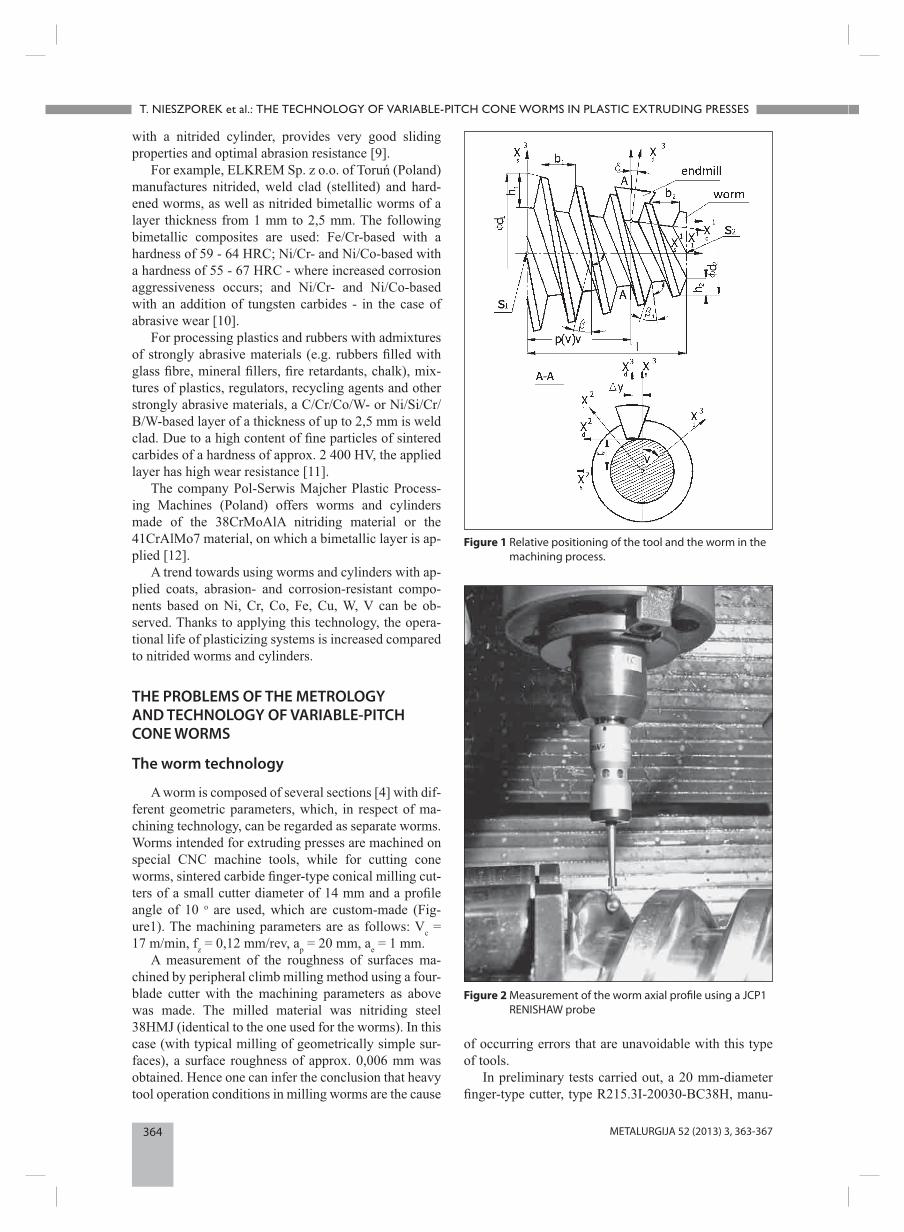
A worm is composed of several sections [4] with dif-ferent geometric parameters, which, in respect of ma-chining technology, can be regarded as separate worms. Worms intended for extruding presses are machined on special CNC machine tools, while for cutting cone worms, sintered carbide fi nger-type conical milling cut-ters of a small cutter diameter of 14 mm and a profi le angle of 10 o are used, which are custom-made (Fig-ure1). The machining parameters are as follows: Vc = 17 m/min, fz = 0,12 mm/rev, ap = 20 mm, ae = 1 mm.
A measurement of the roughness of surfaces ma-chined by peripheral climb milling method using a four-blade cutter with the machining parameters as above was made. The milled material was nitriding steel 38HMJ (identical to the one used for the worms). In this case (with typical milling of geometrically simple sur-faces), a surface roughness of approx. 0,006 mm was obtained. Hence one can infer the conclusion that heavy tool operation conditions in milling worms are the cause
of occurring errors that are unavoidable with this type of tools.
In preliminary tests carried out, a 20 mm-diameter fi nger-type cutter, type R215.3I-20030-BC38H, manu-
Figure 1 Relative positioning of the tool and the worm in the machining process.
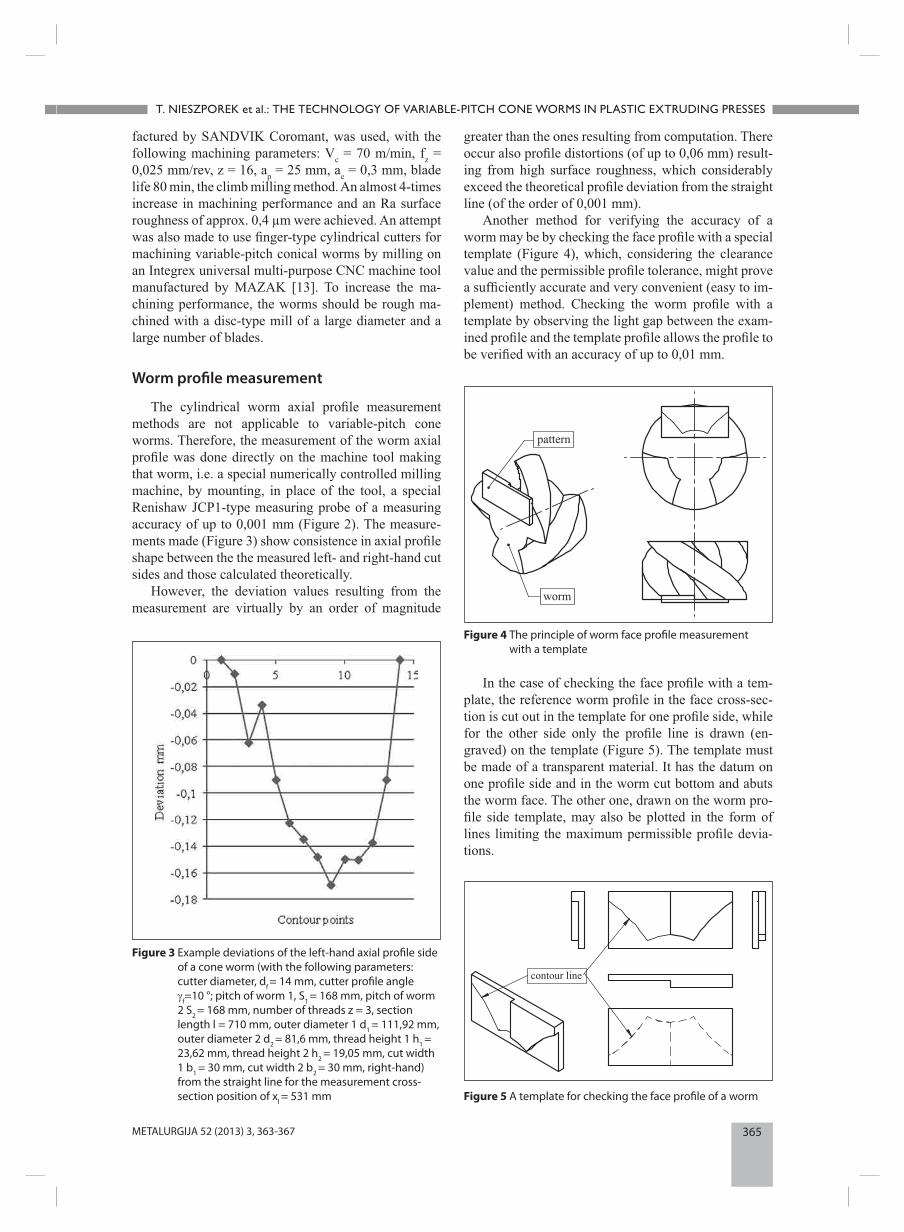
Figure 2 Measurement of the worm axial profi le using a JCP1 RENISHAW probe
365METALURGIJA 52 (2013) 3, 363-367
T. NIESZPOREK et al.: THE TECHNOLOGY OF VARIABLE-PITCH CONE WORMS IN PLASTIC EXTRUDING PRESSES
factured by SANDVIK Coromant, was used, with the following machining parameters: Vc = 70 m/min, fz = 0,025 mm/rev, z = 16, ap = 25 mm, ae = 0,3 mm, blade life 80 min, the climb milling method. An almost 4-times increase in machining performance and an Ra surface roughness of approx. 0,4 µm were achieved. An attempt was also made to use fi nger-type cylindrical cutters for machining variable-pitch conical worms by milling on an Integrex universal multi-purpose CNC machine tool manufactured by MAZAK [13]. To increase the ma-chining performance, the worms should be rough ma-chined with a disc-type mill of a large diameter and a large number of blades.
Worm profi le measurement
The cylindrical worm axial profi le measurement methods are not applicable to variable-pitch cone worms. Therefore, the measurement of the worm axial profi le was done directly on the machine tool making that worm, i.e. a special numerically controlled milling machine, by mounting, in place of the tool, a special Renishaw JCP1-type measuring probe of a measuring accuracy of up to 0,001 mm (Figure 2). The measure-ments made (Figure 3) show consistence in axial profi le shape between the the measured left- and right-hand cut sides and those calculated theoretically.
However, the deviation values resulting from the measurement are virtually by an order of magnitude
greater than the ones resulting from computation. There occur also profi le distortions (of up to 0,06 mm) result-ing from high surface roughness, which considerably exceed the theoretical profi le deviation from the straight line (of the order of 0,001 mm).
Another method for verifying the accuracy of a worm may be by checking the face profi le with a special template (Figure 4), which, considering the clearance value and the permissible profi le tolerance, might prove a suffi ciently accurate and very convenient (easy to im-plement) method. Checking the worm profi le with a template by observing the light gap between the exam-ined profi le and the template profi le allows the profi le to be verifi ed with an accuracy of up to 0,01 mm.
Figure 3 Example deviations of the left-hand axial profi le side of a cone worm (with the following parameters: cutter diameter, df = 14 mm, cutter profi le angle γf=10 °; pitch of worm 1, S1 = 168 mm, pitch of worm 2 S2 = 168 mm, number of threads z = 3, section length l = 710 mm, outer diameter 1 d1 = 111,92 mm, outer diameter 2 d2 = 81,6 mm, thread height 1 h1 = 23,62 mm, thread height 2 h2 = 19,05 mm, cut width 1 b1 = 30 mm, cut width 2 b2 = 30 mm, right-hand) from the straight line for the measurement cross-section position of xl = 531 mm
Figure 4 The principle of worm face profi le measurement with a template
Figure 5 A template for checking the face profi le of a worm
In the case of checking the face profi le with a tem-plate, the reference worm profi le in the face cross-sec-tion is cut out in the template for one profi le side, while for the other side only the profi le line is drawn (en-graved) on the template (Figure 5). The template must be made of a transparent material. It has the datum on one profi le side and in the worm cut bottom and abuts the worm face. The other one, drawn on the worm pro-fi le side template, may also be plotted in the form of lines limiting the maximum permissible profi le devia-tions.
366 METALURGIJA 52 (2013) 3, 363-367
T. NIESZPOREK et al.: THE TECHNOLOGY OF VARIABLE-PITCH CONE WORMS IN PLASTIC EXTRUDING PRESSES
Making only one side of the worm cut face profi le on the template is due to the fact that the template must rest on the edge of the worm face profi le rather than on the thread fl ank (at the distance from the worm face be-ing equal to the template thickness, which results from the inclination of the worm thread helix). For a left-hand and a right-hand worms, two symmetrical tem-plates must be made.
Determination of the clearance between the threads of worms
The clearance is measured using clearance gauge by estimating the light gap between the mating surfaces, or through the magnitude of the angle or rotation of one of the screws with the other being stationary. Only the minimum clearance can be determined this way.
It is assumed that the worm profi le in the axial sec-tion is to be rectilinear, whereas the clearance in the axial section between the threads of meting worms should be constant (of approx. 2 mm) at the profi le height and over the entire worm length. In practice, in spite of these conditions being satisfi ed, it might turn out that in an non-axial section the profi les of mating worms intersect. To eliminate such cases, an analysis of
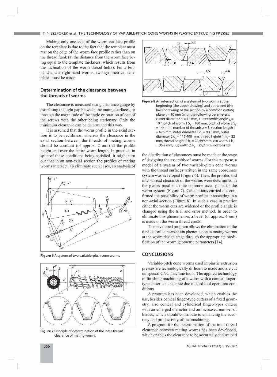
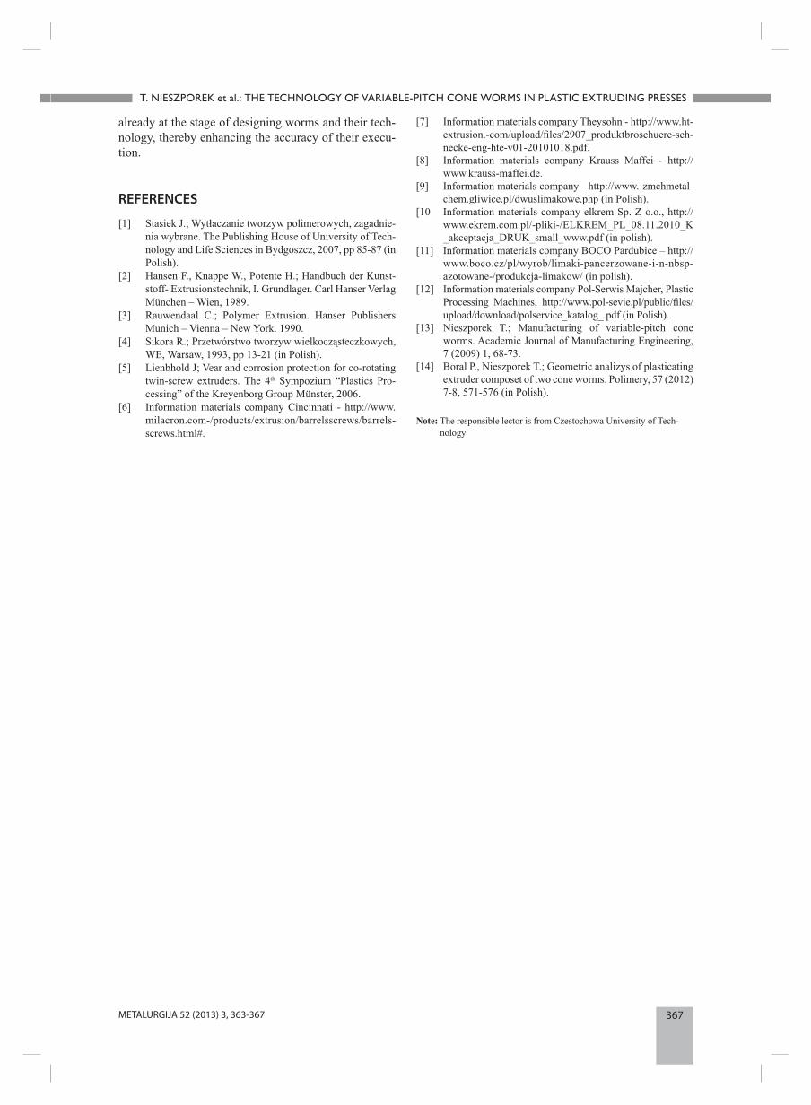
the distribution of clearances must be made at the stage of designing the assembly of worms. For this purpose, a model of a system of two variable-pitch cone worms with the thread surfaces written in the same coordinate system was developed (Figure 6). Then, the profi les and inter-thread clearance of the worms were determined in the planes parallel to the common axial plane of the worm system (Figure 7). Calculations carried out con-fi rmed the possibility of worm profi les intersecting in a non-axial section (Figure 8). In such a case in practice either the worm cuts are widened or the profi le angle is changed using the trial and error method. In order to eliminate this phenomenon, a bevel (of approx. 4 mm) is made on the worm thread crests.
The developed program allows the elimination of the thread profi le intersection phenomenon in mating worms at the worm design stage through the appropriate modi-fi cation of the worm geometric parameters [14].
CONCLUSIONS
Variable-pitch cone worms used in plastic extrusion presses are technologically diffi cult to made and are cut on special CNC machine tools. The applied technology of fi nishing machining of a worm with a conical fi nger-type cutter is inaccurate due to hard tool operation con-ditions.
A program has been developed, which enables the use, besides conical fi nger-type cutters of a fi xed geom-etry, also conical and cylindrical fi nger-types cutters with an enlarged diameter and an increased number of blades, which should contribute to enhancing the accu-racy and productivity of the machining.
A program for the determination of the inter-thread clearance between mating worms has been developed, which enables the clearance to be accurately determined
Figure 6 A system of two variable-pitch cone worms
Figure 7 Principle of determination of the inter-thread clearance of mating worms
Figure 8 An intersection of a system of two worms at the beginning (the upper drawing) and at the end (the lower drawing) of the section by a common cutting plane t = 10 mm (with the following parameters: cutter diameter df = 14 mm, cutter profi le angle γf = 10 °, pitch of worm 1 S1 = 180 mm, pitch of worm 2 S2 = 144 mm, number of threads z = 3, section length l = 675 mm, outer diameter 1 d1 = 90,5 mm, outer diameter 2 d2 = 115,408 mm, thread height 1 h1 = 22 mm, thread height 2 h2 = 24,499 mm, cut width 1 b1 = 35,2 mm, cut width 2 b2 = 29,7 mm, right-hand)
367METALURGIJA 52 (2013) 3, 363-367
T. NIESZPOREK et al.: THE TECHNOLOGY OF VARIABLE-PITCH CONE WORMS IN PLASTIC EXTRUDING PRESSES
already at the stage of designing worms and their tech-nology, thereby enhancing the accuracy of their execu-tion.
REFERENCES
[1] Stasiek J.; Wytłaczanie tworzyw polimerowych, zagadnie-nia wybrane. The Publishing House of University of Tech-nology and Life Sciences in Bydgoszcz, 2007, pp 85-87 (in Polish).
[2] Hansen F., Knappe W., Potente H.; Handbuch der Kunst-stoff- Extrusionstechnik, I. Grundlager. Carl Hanser Verlag München – Wien, 1989.
[3] Rauwendaal C.; Polymer Extrusion. Hanser Publishers Munich – Vienna – New York. 1990.
[4] Sikora R.; Przetwórstwo tworzyw wielkocząsteczkowych, WE, Warsaw, 1993, pp 13-21 (in Polish).
[5] Lienbhold J; Vear and corrosion protection for co-rotating twin-screw extruders. The 4th Sympozium “Plastics Pro-cessing” of the Kreyenborg Group Münster, 2006.
[6] Information materials company Cincinnati - http://www.milacron.com-/products/extrusion/barrelsscrews/barrels-screws.html#.
[7] Information materials company Theysohn - http://www.ht-extrusion.-com/upload/fi les/2907_produktbroschuere-sch-necke-eng-hte-v01-20101018.pdf.
[8] Information materials company Krauss Maffei - http://www.krauss-maffei.de.
[9] Information materials company - http://www.-zmchmetal-chem.gliwice.pl/dwuslimakowe.php (in Polish).
[10 Information materials company elkrem Sp. Z o.o., http://www.ekrem.com.pl/-pliki-/ELKREM_PL_08.11.2010_K _akceptacja_DRUK_small_www.pdf (in polish).
[11] Information materials company BOCO Pardubice – http://www.boco.cz/pl/wyrob/limaki-pancerzowane-i-n-nbsp-azotowane-/produkcja-limakow/ (in polish).
[12] Information materials company Pol-Serwis Majcher, Plastic Processing Machines, http://www.pol-sevie.pl/public/fi les/upload/download/polservice_katalog_.pdf (in Polish).
[13] Nieszporek T.; Manufacturing of variable-pitch cone worms. Academic Journal of Manufacturing Engineering, 7 (2009) 1, 68-73.
[14] Boral P., Nieszporek T.; Geometric analizys of plasticating extruder composet of two cone worms. Polimery, 57 (2012) 7-8, 571-576 (in Polish).
Note: The responsible lector is from Czestochowa University of Tech-nology