Embed Size (px)
Citation preview

Institute of Structural Engineering Page 1
Method of Finite Elements I
Chapter 6
The Timoshenko Beam
Book Chapters[O] V2/Ch2[F] Ch13

Institute of Structural Engineering Page 2
Method of Finite Elements I
Today’s Lecture
• Timoshenko beam theory
• Weak form
• Discretization
• Stiffness matrix – load vector
• Shear locking
Timoshenko beam elements

Institute of Structural Engineering Page 3
Method of Finite Elements I
Reminder: Euler-Bernoulli theory
Assumptions:
Uniaxial Element
The longitudinal direction is sufficiently larger than the other two
Prismatic Element
The cross-section of the element does not change along the element’s length

Institute of Structural Engineering Page 4
Method of Finite Elements I30-Apr-10
Reminder: Euler-Bernoulli theory
Euler/ Bernoulli assumption
Upon deformation, plane sections remain plane AND perpendicular to the beam
axis
z
z
dwu y y
dx
dw
dx
2
2
0
xx
xy
du wy
dx x
dw du dw dw
dx dy dx dx

Institute of Structural Engineering Page 5
Method of Finite Elements I
Reminder: Euler-Bernoulli theory
Valid for:
Slender beams: / 1 /100h L

Institute of Structural Engineering Page 6
Method of Finite Elements I
Timoshenko theory
Assumptions:
Uniaxial Element
The longitudinal direction is sufficiently larger than the other two
Prismatic Element
The cross-section of the element does not change along the element’s length

Institute of Structural Engineering Page 7
Method of Finite Elements I30-Apr-10
Timoshenko theory
Timoshenko assumption
Upon deformation, plane sections remain plane but not necessarily perpendicular
to the beam axis
z
z
dw
dx
z z
dw
dx

Institute of Structural Engineering Page 8
Method of Finite Elements I
Timoshenko theory
Valid for:
Slender beams:
Thick beams:
/ 1 /100h L
/ 1 /10h L

Institute of Structural Engineering Page 9
Method of Finite Elements I30-Apr-10
Timoshenko theoryDisplacements
Strains
z z
dwu y y
dx
w w x
, 0
0
zxx yy
xy z
u wy
x x y
w u w w w
x y x x x
Stresses
,
2 1
xx xx
xy xy
E
EG G

Institute of Structural Engineering Page 10
Method of Finite Elements I30-Apr-10
Timoshenko theoryCross sectional forces – Bending Moment
2z zxx xx z z
A A A A
d dM y dA E y dA E y y dA E y dA EI
dx dx
M
xx
x
y
Normal stress distribution
where:
2
z
A
zz
I y dA
d
dx
Or:
b z
b z
M D
D EI
→ moment of inertia
→ bending strain/curvature

Institute of Structural Engineering Page 11
Method of Finite Elements I30-Apr-10
Timoshenko theoryCross sectional forces – Shear Force
xy xy xy xy
A A A
V dA G dA G dA GA
x
y
xy
Vx
y
xy
V
Actual shear stress distribution Assumed shear stress distribution
,
2 1A
EA dA G
where:
Or:
,s xy sV D D kGA where is introduced to account for the actual stress distribution 1k

Institute of Structural Engineering Page 12
Method of Finite Elements I30-Apr-10
Timoshenko theoryShear Correction parameter for standard cross sections
5 / 6k 6 / 7k 0.32k
0.416k 0.5k 0.358k

Institute of Structural Engineering Page 13
Method of Finite Elements I30-Apr-10
Timoshenko theoryEquilibrium equations (identical to Bernoulli beams)
Force equilibrium
Moment equilibrium
y
dVf x
dx
dM
V xdx
Combined
2
2 y
d Mf x
dx
yf x

Institute of Structural Engineering Page 14
Method of Finite Elements I30-Apr-10
2
22 3
const
2 3
y
EIz zz z z y z y
zz
d Mf x
dxd d d
M EI k EI f x EI f xdx dx dx
dk
dx
Timoshenko theoryEquilibrium equations in terms of deflections
Equilibrium + Moment-curvature relation + Curvature definition
Force equilibrium + Shear force-Shear strain relation + Shear strain definition
2
const
2
y
ykGA zxy z y
xy z
dVf x
dxf xd dw d d w
V kGA kGA f xdx dx dx dx kGA
dw
dx

Institute of Structural Engineering Page 15
Method of Finite Elements I30-Apr-10
3
243
4 22
2
zz y
yzz y
yz
dEI f x
d f xd w EIdxEI f x
dx kGA dxf xd d w
dx dx kGA
Timoshenko theoryEquilibrium equations in terms of deflections
Combining the two expressions

Institute of Structural Engineering Page 16
Method of Finite Elements I30-Apr-10
3
243
4 22
2
zz y
yzz y
yz
dEI f x
d f xd w EIdxEI f x
dx kGA dxf xd d w
dx dx kGA
Timoshenko theoryEquilibrium equations in terms of deflections
Combining the two expressions
Comparison to Bernoulli-Euler theory
24
4 2
yzz
d f xd w EIEI p x
dx kGA dx
4
4z y
d wEI f x
dx
Timoshenko Bernoulli-Euler

Institute of Structural Engineering Page 17
Method of Finite Elements I30-Apr-10
Weak formPrinciple of Virtual Work
0
InternalVirtualWork ExternalVirtualWork
L
xx xx xy xy y z i yi zi i
i iV
dV w f m dx w F M
where:
yf
m
yiF
iM
→ distributed force
→ distributed moment
→ nodal force
→ nodal moment

Institute of Structural Engineering Page 18
Method of Finite Elements I30-Apr-10
Weak form
Bending Shear
0 0
0 0
xx xx xy xy xx xx xy xy
V V V
zxx xy xy
V V
L L
zxx xy xy
A A
M V
L L
zxy
dV dV dV
dy dV dV
dx
dy dA dx dA dx
dx
dM dx V
dx
0 0
L L
z zb xy s xy
dx
d dD dx D dx
dx dx
Internal Virtual Work

Institute of Structural Engineering Page 19
Method of Finite Elements I30-Apr-10
2 2
2 2
0 0b
z zzzizz
L L
z y i yi i
i i iDdd
dxdx
d w d w dw dwEI dx w f m dx w F M
dx dx dx dx
0 0 0
z z
L L L
z zb xy s xy y z i yi zi i
i i
d dD dx D dx w f m dx w F M
dx dx
Weak formPrinciple of Virtual Work
Principle of Virtual Work – Euler Bernoulli theory

Institute of Structural Engineering Page 20
Method of Finite Elements I30-Apr-10
Weak formPrinciple of Virtual Work
0 0 0
L L L
z b z xy s xy y z i yi zi i
i i
D dx D dx w f m dx w F M
Principle of Virtual Work – Euler Bernoulli theory
0 0
L L
z b z y z i yi zi i
i i
D dx w f m dx w F M

Institute of Structural Engineering Page 21
Method of Finite Elements I30-Apr-10
Discretization
Two noded beam element
Isoparametric coordinates are used
Independent assumptions need to be made for the deflections and rotations
4 dofs are available in total (1 deflection and 1 rotation per node)
A linear assumption is made for both the deflections and the rotations:
2l
1 1 0
0 1 0 1, zw a a b b

Institute of Structural Engineering Page 22
Method of Finite Elements I30-Apr-10
DiscretizationShape functions – Linear isoparametric
2l
1 1 0
1N
-1 1
2N
-1 1
Geometry
1
1 1
2
xx N N
x
2
2 2,
1 11 ,
2 2
dNN N
d
1
1 1,
1 11 ,
2 2
dNN N
d
1
1, 1,
2
1 2 1
2
1 1
2 2 2 2
xdxJ N N
xd
x x x L
x
1 2dJ
dx L

Institute of Structural Engineering Page 23
Method of Finite Elements I30-Apr-10
DiscretizationDisplacements – Virtual Displacements
1
1 2
2
1
1
1 2
2
2
1
1
1 2
2
2
or
0 0
0 0
z
z
z
z
ww N N
w
w
w N Nw
w
w N Nw
w
w
w
N
u
w
N
u
N u
N u
1
1 2
2
1
1
1 2
2
2
1
1
1 2
2
2
or
0 0
0 0
z
z
z
z
z
z
z
z
z
N N
w
N Nw
w
N Nw
θ
θ
θ
N
u
θ
N
u
N u
N u
Rotations – Virtual Rotations

Institute of Structural Engineering Page 24
Method of Finite Elements I30-Apr-10
DiscretizationBending strain – Virtual bending strain
1 1
1 1
1 1
1, 2, 1, 2,
2 2
2 2
1
1
2
2
0 0 0 0
1 2 1 20 0
2 2
1 1, , 0 0
z zzz x x
J Jz z
z
z
z z
w w
d d dN N N N
w wdx dx dx
w
wL L
L L
bB
u
b b bB u B u B

Institute of Structural Engineering Page 25
Method of Finite Elements I30-Apr-10
DiscretizationShear strain – Virtual shear strain
1 1
1 1
1, 2, 1 2
2 21 1
2 2
1
1
2
2
0 0 0 0
1 1 1 11 1
2 2
1 1, , 1
2
z z
xy x x
L Lz z
z
z
xy xy
w w
dwN N N N
w wdx
w
wL L
L
sB
u
s s sB u B u B 1 1
12L

Institute of Structural Engineering Page 26
Method of Finite Elements I30-Apr-10
Stiffness Matrix – Load VectorPrinciple of Virtual Work (distributed moments and nodal forces ignored)
0 0 0
L L L
z b z xy s xy yD dx D dx w f dx
Substituting the discretized fields
0 0 0
L L L
T T T T T T
b s y
T
D dx D dx f dx
b b s s wu B B u u B B u u N
u0
L
T T
bD dx b bB B u u
0
L
T T
sD dx s sB B u u
0
0 0 0
L
T
y
L L L
T T T
b s y
f dx
D dx D dx f dx
w
b b s s w
fK
N
B B B B u N

Institute of Structural Engineering Page 27
Method of Finite Elements I30-Apr-10
Stiffness Matrix – Load VectorStiffness matrix
0 0
, ,
L L
T T
b sD dx D dx b s b b b s s sK K K K B B K B B
Load Vector
0
L
T
yf dx wf N
1 10 0 ,
1 1 1 11 1 ,
2 2
b z
s
D EIL L
D kGAL L
b
s
B
B
1 1
1 0 1 02 2
wN

Institute of Structural Engineering Page 28
Method of Finite Elements I30-Apr-10
Stiffness Matrix – Load VectorStiffness matrix – Analytical integration
1
0 1
0 0 0 0
0 1 0 1
0 0 0 0
0 1 0 1
L
T T
b b
b
z
D dx D Jd
D
L
EI
L
b b b b b
b
bb
K B B B B
K
K K

Institute of Structural Engineering Page 29
Method of Finite Elements I30-Apr-10
Stiffness Matrix – Load VectorStiffness matrix – Analytical integration
1
0 1
0 0 0 0
0 1 0 1
0 0 0 0
0 1 0 1
L
T T
b b
b
z
D dx D Jd
D
L
EI
L
b b b b b
b
bb
K B B B B
K
K K
→ Similar to a bar element!

Institute of Structural Engineering Page 30
Method of Finite Elements I30-Apr-10
Stiffness Matrix – Load VectorStiffness matrix – Analytical integration
1
0 1
2 2
2 2
2 2
2 2
1 1 1 11 1
2 2 2 2
1 1 1 1
2 3 2 6 2 3 2 6
1 1 1 11 1
2 2 2 2
1 1 1 1
2 6 2 32 6 2 3
L
T T
s s
ss
D dx D Jd
L L
L L L L
L L L L
D L LD L kGAL
L LL
L L L L
L L L L
L L
s s s s s
ss
K B B B B
K K

Institute of Structural Engineering Page 31
Method of Finite Elements I30-Apr-10
Stiffness Matrix – Load VectorLoad vector– Analytical integration
0 0
2
0
2
0
L L
T T
y y
y
y
f dx f Jd
f
f
w wf N N
f

Institute of Structural Engineering Page 32
Method of Finite Elements I30-Apr-10
Stiffness Matrix – Load VectorLoad vector– Analytical integration
0 0
2
0
2
0
L L
T T
y y
y
y
f dx f Jd
f
f
w wf N N
f → Also similar to a bar element!

Institute of Structural Engineering Page 33
Method of Finite Elements I30-Apr-10
Stiffness Matrix – Load VectorStiffness matrix – Numerical integration
1
0 1
L
T T T
b b i i b i
i
D dx D Jd w D J
b b b b b b bK B B B B B B
Stiffness matrix – Required number of Gauss points

Institute of Structural Engineering Page 34
Method of Finite Elements I30-Apr-10
Stiffness Matrix – Load VectorStiffness matrix – Numerical integration
1
0 1
L
T T T
b b i i b i
i
D dx D Jd w D J
b b b b b b bK B B B B B B
Stiffness matrix – Required number of Gauss points
1 10 0 constant
constant
constant
constant 0
b
T
i b i
L L
J
D
D J p
b
b b
B
B B
→ 1 Gauss point is enough

Institute of Structural Engineering Page 35
Method of Finite Elements I30-Apr-10
Stiffness Matrix – Load VectorStiffness matrix – Numerical integration
1
0 1
L
T T T
s s i i s i
i
D dx D Jd w D J
s s s s s s sK B B B B B B
Stiffness matrix – Required number of Gauss points

Institute of Structural Engineering Page 36
Method of Finite Elements I30-Apr-10
Stiffness Matrix – Load VectorStiffness matrix – Numerical integration
1
0 1
L
T T T
s s i i s i
i
D dx D Jd w D J
s s s s s s sK B B B B B B
Stiffness matrix – Required number of Gauss points
1 1 1 11 1 linear
2 2
constant
constant
quadratic 2
s
T
i s i
L L
J
D
D J p
s
s s
B
B B
→ 2 Gauss points are
required

Institute of Structural Engineering Page 37
Method of Finite Elements I30-Apr-10
Stiffness Matrix – Load VectorLoad vector – Numerical integration
0 0
L L
T T T
y y i i y
i
f dx f Jd w f J w w wf N N N
Load vector – Required number of Gauss points

Institute of Structural Engineering Page 38
Method of Finite Elements I30-Apr-10
Stiffness Matrix – Load VectorLoad vector – Numerical integration
1
0 1
L
T T T
y y i i y
i
f dx f Jd w f J
w w wf N N N
Load vector – Required number of Gauss points
1 1
1 0 1 0 linear2 2
constant
constant
linear
y
T
y
J
f
f J
w
w
N
N
→ 1 Gauss point is enough

Institute of Structural Engineering Page 39
Method of Finite Elements I30-Apr-10
Shear lockingExplanation
Consider a 2 noded beam under pure bending:
For a slender beam no shear strain should occur, however since
1constzz z
dM EI b
dx
1 1 0xy z
dwa b
dx
0 1w a a
→ shear strain is not zero for any value of 1a

Institute of Structural Engineering Page 40
Method of Finite Elements I30-Apr-10
Shear lockingGeometrical interpretation
Element deformation for a slender beam Actual deformation of a slender beam
1z 2z
1 2
xy0xy

Institute of Structural Engineering Page 41
Method of Finite Elements I30-Apr-10
Shear lockingIn terms of the system of equations
2
3
z zEI EI kGAkGAL L
L L L
b s b sb s
K K K K K K K
Ku f
Assuming an orthogonal cross section:
3
3
3
2
2
5
6 2 112
5
12 12 1
h
EbhbhE
LL L
Eb Eb h
LL
L
b s
b s
K K K
K K
Since for slender beams ,
the shear term dominates the bending
one leading to artificially stiff systems
3h h
L L

Institute of Structural Engineering Page 42
Method of Finite Elements I30-Apr-10
Shear lockingIn terms of the system of equations
As the beam becomes more slender , the coefficient of the shear term
increases much faster than the one of the bending term
The higher coefficient of the shear term can be seen as penalty parameter rendering
the system stiffer
At the limit, the system becomes extremely stiff leading to a “locking” effect
For general cross sections, the thickness to length ratio affects the results similarly
3
2 5
12 12 1
zEI Eb EbkGAL L
h h
L LL
b s b sb sK K K K K K K
Ku f
0h
L

Institute of Structural Engineering Page 43
Method of Finite Elements I30-Apr-10
Shear lockingA first remedy: Reduced integration
Locking is essentially caused by the “spurious” linear term in the shear strain:
Ignoring the energy produced by that term would remove locking effects
A simple way of improving the performance of the element, is to simply reduce the
integration order used for the shear term
Using a single Gauss point can accurately integrate functions of order 2x1-1=1, thus the
quadratic terms produced by the “spurious” linear term cannot be accurately integrated
1 1xy z
dwa
dxb

Institute of Structural Engineering Page 44
Method of Finite Elements I30-Apr-10
Shear lockingA first remedy: Reduced integration
Shear part of the stiffness matrix using full and reduced integration:
2 2
2 2
1 12 2
2 2
1 12 2
4
2 2
4
4 4
s
L L
L L
D
L LL
L
L L
L L L
r
sK
2 2
2 2
1 12 2
2 3 2 6
1 12 2
2 6 2 3
s
L L
L L L L
D
L LL
L L L L
sK
Reduced integrationFull integration
Institute of Structural Engineering Page 45
Method of Finite Elements I30-Apr-10
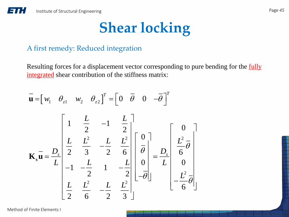
Shear lockingA first remedy: Reduced integration
Resulting forces for a displacement vector corresponding to pure bending for the fully
integrated shear contribution of the stiffness matrix:
2 2 2
2
2 2
1 102 2
0
2 3 2 6 6
0 01 1
2 2
6
2 6 2 3
s s
L L
L L L L L
D D
L LL L
L
L L L L
sK u
1 1 2 2 0 0TT
z zw w u

Institute of Structural Engineering Page 46
Method of Finite Elements I30-Apr-10
Shear lockingA first remedy: Reduced integration
Resulting forces for a displacement vector corresponding to pure bending for the shear
contribution of the stiffness matrix obtained using reduced integration:
2 2
2 2
1 12 2
0 0
02 4 2 4
0 01 1
2 2 0
2 4 2 4
s
L L
L L L L
D
L LL
L L L L
r
sK u
1 1 2 2 0 0TT
z zw w u
→ The shear term yields no forces!

Institute of Structural Engineering Page 47
Method of Finite Elements I30-Apr-10
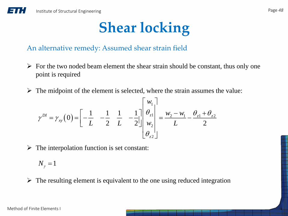
Shear lockingAn alternative remedy: Assumed shear strain field
An alternative interpolation scheme can be used for the shear strain:
where:
DI
xy γN γ
γN
DIγ
→ a vector of interpolation functions used for the shear stain
→ a vector of shear strain values computed at specific interpolation points
Institute of Structural Engineering Page 48
Method of Finite Elements I30-Apr-10
Shear lockingAn alternative remedy: Assumed shear strain field
For the two noded beam element the shear strain should be constant, thus only one
point is required
The midpoint of the element is selected, where the strain assumes the value:
The interpolation function is set constant:
The resulting element is equivalent to the one using reduced integration
1
1 2 1 1 2
2
2
1 1 1 10
2 2 2
zDI z zxy
z
w
w w
wL L L
1N