Embed Size (px)
Citation preview

HWAHAK KONGHAK Vol. 40, No. 4, August, 2002, pp. 498-506
����� ��� �� ��� ���� � �� ��
���*����*,** †
*����� ��� ����� , **����(2002� 2� 4� ��, 2002� 7� 11� ��)
The Ultra-fine Grinding Mechanism of Inorganic Powders in a Stirred Ball Mill
Hee Kyu Choi* and Woo Sik Choi*,** †
*Interdisciplinary Program in Powder Technology Graduate School, **Dept. of Pharmaceutical, Manufacturing,Pusan National University, Busan 609-735, Korea(Received 4 February 2002; accepted 11 July 2002)
� �
�� ��� ��� �� ���� ���� ���, �����(submicron) ��� �� � !"� #$ �%.
&', � �(� �� � ��)* +, -./$, 012345 67 7./� 89: ;<=( �> ?@ 67 �A/
$ �%. B ?@(�� CDE, FE, GE HI JK L� MNO PQ: ;<R=� -.> S� ��(� ;<R=�
�TUVW(mechanism)� X'� Y� "234 �Z%. ([*&\� ]-�K ^D ��]_]`� *� �O (
[*ab�� 0cd DE�K ^D �K� �e fg� hi�Z$, j ��]_kl( m> 0cd nc234
DE�� opq� rs�Z%. t,$, j ��]`(� �([* uv� wx�� �]r �uv� �y( �z�
�{� ]-��, �]rd -.�Z� |, �]rd -.�* }$ �2� uv� ~���� ��]_]` �% �
uv7 � 13.1% �y� Y� � P ��%. �>, ��� �7�( ��5�� 2., ��50P( �z� ���5, �
�, �5 � �]r � � �{� ��234 wx��, ���N� �\7 ��*�~ ��]_]`� �,�� ��
( ��]_kl ��5( �z� �{� ��50P� ��d nD � P ��$, �]rd -.�* }�� |(
eD �m 25.6%� ��5 ���� ��%.
Abstract − Recently in various industrial processes, the need for fine particles especially submicron particles has been
increased in preparation field of raw powders such as fine ceramics and high technical products. The grinding by a stirred ball
mill to submicron range has been achieved commercially in many cases. A series of grinding experiments using a vertical
stirred grinding media mill and inorganic powders such as calcite, pyrophyllite and talc as test samples were carried out to clar-
ify the grinding mechanism of the stirred grinding media mill. The effect of experimental conditions such rotation speed of stir-
rer, ball filling ratio, ball diameter and slurry concentration on the power inputted in the stirred media mill were measured andthe quantitative relationship between them was proposed with multiple regression analysis. The relationship between the exper-
imental factors and the comminution consumption power could also be regressed as a power-law and effect of grinding aids on
particle size distribution and on grinding efficiency defined as the increase of specific surface area per the specific grinding
consumed energy was investigated. In this study it can be concluded that the grinding energy efficiency using grinding aids was
improved about 13.1% than no aids experiment. And the effect of grinding aids on grinding rate constant K was investigated.
Also the relationship between grinding rate constant K and experimental conditions including the effect of grinding aids was
examined and it is confirm that the grinding rate can be improved in the degree of the maximum of 25.6% compared with with-
out grinding aids.
Key words: Stirred Ball Mill, Grinding Mechanism, Ultra-Fine Grinding, Inorganic Powder, Grinding Additive
498
†To whom correspondence should be addressed.E-mail: [email protected]

���� ���� � � � 499
1. � �
����� ���, �, � � �� ��� �� ���� �
�, �� �� � !"(fine ceramics)# �$%& ' ()*+ ,-�
��� ./�+ 01� 2� 3$4 5�6� 7 8 ��94 :;
<=>? �:. ��, @AB� �� �C4 ��;>? �%�, DEF
G4 4 �H# IJ�K ��@& LMN? �:. DEFG� 1928O
.P+ UNION PROCESS Q+ Dr. Szegvari� +�R SH ,->T
?, 1948O “Attritor” K UV%& WX�>T:. DEFG ��@+
YQK Z� 50R O �[4\I ��� ����4 �H>K C]^
_�� ��' `a# �? �%�, �b� ()*+ ,-� cd @R
�? �:. Pe��+ FG� 3' SH# fghi, 1977O �]jk
l� +m “FG� 3' ;n�”o 0p>T?, 8 q&[ rs' SH
o A�>�t:. ^* DEFG� 1µm 4� uv.w c@+ ��o
ox�? Fy �z+ �@ ,-, {|+ ���z+ ,-� +�R
�z+ c@o 0.2-0.3 mm+ Q}4 ox�d 6y ~;� x�[ �
�B%& �W>T:. 8�u, 4�' SH�� ?�B� ��4�� +
��R G 0p+ @�B� �i�I MB� � �4�u, �� �+ �
# `' � � �`��%&� ��B� 1� ��� 7� �9B
^W�I� ��' �4 �<�4T:. �, ����� ��� ��B
� �� @H� 3' SHK .�' ��4:.
YQB%& F � ��� 3' SHK L& �� ��\� ��@+
�x �� S3�K �%& j >� t%�, �� q ¡�j �¢��
�� @H# �� �£�;¤ ��4��� m¥>� t:[1,2]. 8�u
����� 0��?, �B�;¦K §K ���9� 3' ¨© HzB
� �¢o �Hª:. Bernhardt[3] �� «� ¬[o ���� ®
¯�� °±:? ²³ ´ �%�, Gao �[4]� µ¶· DEG�� ��
~��� ¸�¹ µ �K �º� �»?, Zheng[5] �� = �º�µ�
����\ �� 3m DE�zG�� @¼ SH# µ �»:. ½
¾� �9� �¿# ¡Ày � ����\� �' �ÁiB+ Âo&
uÃÄ ���� ?Å�K �� Jimbo �[6-9]�� 2� SHo m
Æ t?, �� ���z+ ÇÈ� +' ���[+ ,É[6]y Ê9FG
� Q}' ��10+ �y �[9]� �m�K Ë SH��� 4. ÌÂ
ª ´ �:.
Paramasivam �[10]� �Í���� Îz ��10+ �9� �m S
H' ´ �%� R@�K ÏÍ��;� �4 Ð�Áiy ��� Q4
+ � B EÑ, .�Ð�o ���z Q4�� Ò� Ð�o ��Ó Ô
Õ� Ö4K ×Ø�y# Ù);¦K �(Ziegler, 1956, Locher �, 1972)
%& 8 �zo ��10& ?ÚÓ µ �K �yK :� �9� uÃe
? �:[11-14].
½', ���[Wµ� 3' �ºB ÌÛ[ :{' nÜ%& m\?
�:[13,14]. Choi �[13]� +�i Ê9FG�� ���[ Wµ+ m¥
� Ý' .�� �9� ÞU�»?, Kanda �[14]� +�i j~G��
���[ Wµ+ �ºB ÌÛ# �»:.
7 �, Ë SH��K DEFG ��@H+ ��B� mU� `�R,
DE�[, �zØ�, �zß, «� ¬[ � �º1p��� )�~
�y+ W33A# ÌÛ�? @à+ áâÍ� B}�R µã· DEG
+ ��~��� ¸��?� �»?, Ð[�¿ ��+ 3Å� Ým ¾
� �9� �¿# ¡Ày, � ����\� �' �ÁiB+ Âo& u
ÃÄ ���� ?Å�?� �»:. ½', �º*¢+ �94 ä \
�u �º1p1�� äå� ß�� ���[�� +�' ���[
Wµ+ ��# ÌÛ�R �º1p��o ���[� .aK ¯�� æ
?, �B 1p1�+ ÌÛ ç ¶oo ox'o# ÌÛ�»:. ��, �
�10# Q}¹ ß�� ���+ Âo� ���[Wµ+ ��# �
ºB%& ?Å�?� �»:.
2. ���� �
2-1. ����
2-1-1. DEFG
���º_a&K ?Ú)*,-(L) KMD-1B µã· �z· DEG
4 Q}>T:. Fig. 1� �º�Þá è�Í µã· �z· DEG+ a
µ� á{� [m�R 0;':. DEG+ ��� eéy DEê,�K
ë�ìí(poly-urethane) îï4 >� ��, ���º � -ð¹ µ �
K ñò� �)��»:. ��@�K DE@(stirrer)# ó? ô@ `m
õö ox' ���4 �?, ��� �÷�K è��K DE@o `a
':. DE@�K ãß 10.0 mm, ø4 78.0 mm+ ù ,+ �Ý· DE
ú4 û� �:. ��� e}B� 0.95l4?, DE@+ É�y ���
´üQ4�K 5.0 mm �[+ ýþ� ÿ[� �a�»:[1,2]. ½' �
�� L`�K �[Wõ� �@ `m �=µ# �Úhe[� >��:.
�=µK �E µ��� Q}�»:.
2-1-2. ���z
���zK eá9 æ.u(alumina, �Ë NIKKATOQ, £[ 99.9%+
Al2O3, φ=1.0 mm(−1.41/+0.84*), φ=2.0 mm(−2.36/+2.00), φ=3.0 mm(−3.36/
+2.83) jG[ 3.6 g/cm3) F� Q}�»:. F+ �/� `m�K Ás
�z('P, lAW�Q)# Q}�»:.
2-1-3. ��;¢
��;¢K =� C]�� 4}>? �K nm¥(calcite, (L)�Á
� , S500, x50=6.42µm, jG[=2.72 g/cm3), �¥(talc, (L)�Á� , TS-
1000, x50=10.48µm, jG[=2.74 g/cm3), �¥(pyrophyllite, (L)�Á�
, PLW, x50=4.07µm, jG[=2.73 g/cm3)� Q}�»:. ��10K
��� (L)%&<w 0�N� Q}�»:.
2-1-4. )�~� �� _a
DEG� H~�K )�~�� �Ô�d ���@ `m �b äÚ�
� D�áw# ã�áw& Dz�»:. �~��1�@(AVR, 9(��
*1.41 mmk 9�� � 9d n��$ 0.84 mmk 9�� � 9 ̂ ( I R� �894 -.�Z%. t ¡I K�¢£� ¤�Z%.
Fig. 1. Dimensions and shape of grinding mill pot of experimental stirredmedia mill.
HWAHAK KONGHAK Vol. 40, No. 4, August, 2002
500 �������
GPA 100SS)� �zB%& 0p' ��è&# Ým )�~�+ ���
`' _a# <��»:. ã�áw+ y��# �@ `m field�K �
�� 70 V# LT?, armature�K DEú+ è��[# 1��@ `m
« 4ü"(slidacs, (L)'���", �þ}� 2 kVA)& S��R o�
��� <��»:. ~�ACÍ+ �CAµK ��.w(multimeter,
SANWA ELECTRONIC)# 4}' µ~ A�� +m Ì��»:.
2-1-5. Ð[�¿ �� _a
Ð[�¿ ��� ì4�(laser) è��C�+ �# 4}' mastersizer
microplus(Malvern, ̄ P)# Q}�»:. Ð[�¿ �� ;�K < �
C@& ¼À��C@(Ninonseiki Kaishap), US-300T, tipß φ=20 mm,
�Ë)# Q}�R �C;!:.
2-2. ����
2-2-1. ���ºnÜ
)�+ �º1�� �z+ "~�[(DEú+ è��[), ��;ý,
G e+ 1�(F Ø�, F c@, «�(slurry) ¬[) �� == �#
' o\# ?�;¤ W$�� :� 1�+ ��# Ý' �º� �»
%�[1, 2], ==+ �º1�� Table 1� uÃeT:.
F � JK J=0.3, 0.5, 0.7+ � o\ 1�%& ��;%, ���
e }B�� DEúy ê,+ }B� 0 ' Ê� e}B 910 ml��
J=0.3 � � 590 g, J=0.5 � � 980 g, J=0.7 � � 1,380 g+ F� &'
:. ���zß� φ=1.0, 2.0, 3.0 mm& ��;% �º�»:. ���
e�� ;¢� ���z 8? �+ <(# ©' zB4 �z ���
+ 80% � � �y ���z# È' |�+ |�@s )�� ==
10(;¢�: 38 g), 20(;¢�: 82 g), 40(;¢�: 192 g) wt%& �R �º
� �»:[9]. «� ¬[K |�@s%&� :À Í%& AC�»:.
(1)
R@�, CsK «� ¬[, msK *++ |�, mwK �+ |�4:.
;¢# ,Ð�R ��;ý� 7� )� ~�� ���?, ½, �9�
+ Ð[�¿� �ÁiB� ���@ `�R �mj ;ý: *+-
(sampling)� �»:. ½', �¢K . 10è� /0 Ð[��� �R =
=+ 1[, BC�¿+ ¶2y Ás�3# H�»:.
�ÁiB� �¢� �9�+ Ð��� H& o��R Ð[�¿��
§4w&<w Í (2)� 4}�R AC�»:[13].
(2)
R@�, ViK iHý e+ �zÐ�+ <(, diK iHý e+ Ð��+ ¶
2ß, ρpK Ð�+ G[, D[3, 2]K ziB¶2ß4:.
2-2-2. )�~�+ ��nÜ ç §4w m¥nÜ
���e DEúy ��� ´üy+ Å� ���d Ê\�i� F
+ Ê~� ���d �@ `m� DEú É�y ��� ´ü� 5.0 mm
+ ýþ� ÿ? è��»:. ~���� DE�[o 4�' W$� [
ä>T� � ,;�»:. ½', Ë �º ,; � 1;ý �<w ̧ �"��
Ý�R _a# 4��;!:[10]. ��@ e� ;¢# ,Ð�R 800 rpm
�� �� 'A� [ä�K ;ý4 ð=>K 15� ~4 ��' q, D
E�[# ��;¤ ì5�� �?a& 6' 700 rpm��<w 300 rpm
7\ = 30¼8 10è� /0 5� ~4 ���R ¶29� 6�»:.
�º ; ��@+ )�~�� :;wW�� �_¹ �K � 2¼ ½K
5�: ‘Excel’ <&8=%&, µ~%& A�� ¹ �K 5�: A@
>� Á;ª µa# @��»:. )�~�+ �� 8b<K �_ª §
4w# ‘Sigma Plot’ <&8=%&, �º1p��� ~�y+ è?�¥
�yK ‘Sigma Plot’ e+ AC@x� 4}�»%�, ‘SPSS’ <&8=
+ :�É· è?�¥ @x� Q}�R �zB� ;ºáâ+ Wµ�,
è?Aµ 9� H�»:.
2-2-3. ��10 ,ÐnÜ
��10+ ;¢ { ��� ;¢# 0�' ��� (L)+ ߺB µ
a� ���R 40 wt%+ ¬[& >��K ��10+ {4 �z ;¢
+ 1.2 wt%o >[� �R �º� �»:. ��10+ ,ÐnÜ� ��
�º ;p ; ��10 0.2 wt%# ,Ð�R 13�ý ��# ' q 13�
�� 73�7\ 60�ý S�B%& 1.0 wt%# ,Ð�R ���º� �
»:. 73�4 \@ q 120�7\ 47�ý ��10 A4 Bo& �� �
º� �R . 120� ~4 ���»:.
3. � ��
3-1. ���� ��
3-1-1. DE�[+ ¯�
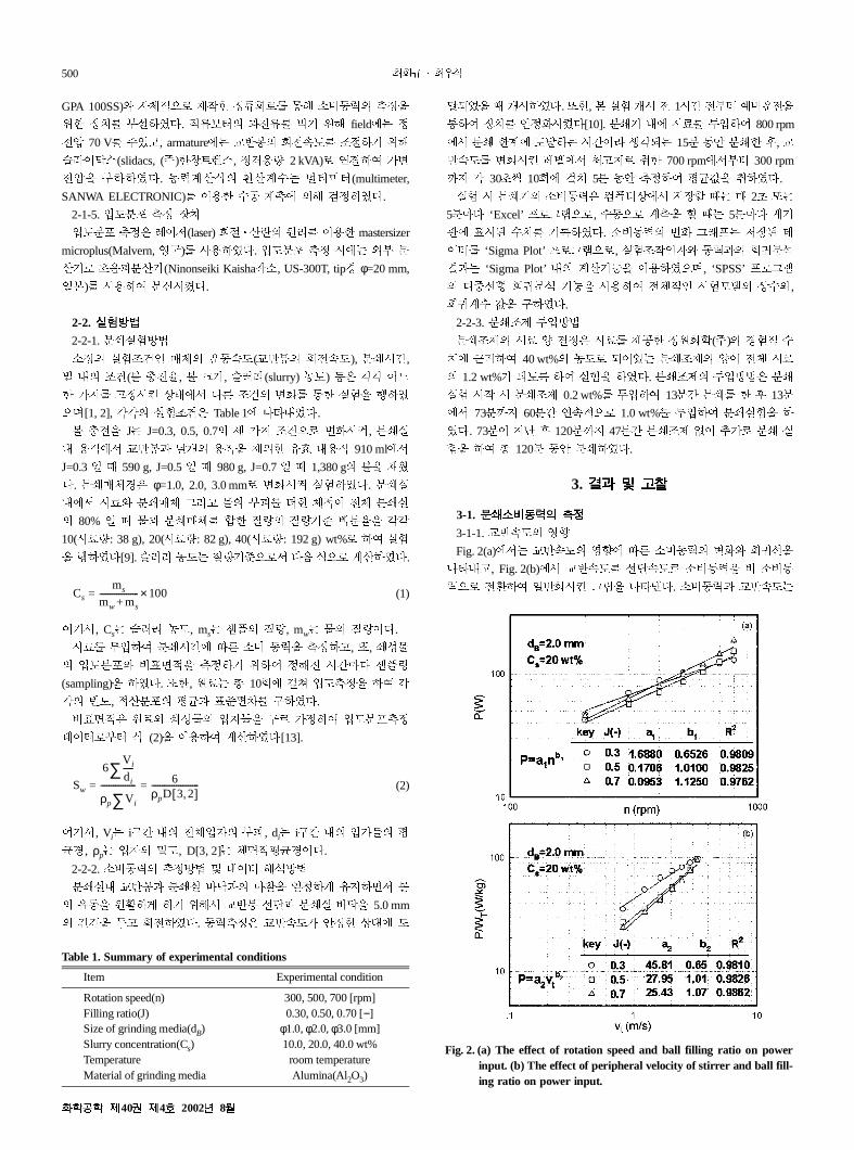
Fig. 2(a)��K DE�[+ ¯�� 7� )�~�+ ��� è?É�
uÃe?, Fig. 2(b)�� DE�[# É��[& )�~�� � )�~
�%& ���R �E�;¤ 8C� uÃÄ:. )�~�y DE�[KCs
ms
mw ms+------------------- 100×=
Sw
6V i
di
-----∑ρp V i∑----------------- 6
ρpD 3 2,[ ]-----------------------= =
Table 1. Summary of experimental conditions
Item Experimental condition
Rotation speed(n)Filling ratio(J)Size of grinding media(dB)Slurry concentration(Cs)TemperatureMaterial of grinding media
300, 500, 700 [rpm]0.30, 0.50, 0.70 [−]
φ1.0, φ2.0, φ3.0 [mm]10.0, 20.0, 40.0 wt%
room temperatureAlumina(Al2O3)
Fig. 2. (a) The effect of rotation speed and ball filling ratio on powerinput. (b) The effect of peripheral velocity of stirrer and ball fill-ing ratio on power input.
���� �40� �4� 2002� 8�

���� ���� � � � 501
�b� D� 3AÍ� 7 è?�¥ �»:(Fig. 2(a), (b)� +m).
(3)
(4)
R@�, PK )�~�, n� DE�[, vtK DEê,+ É��[, WT
K ��� e+ . |�%&E, �y ���z# È' 94:. a1, a2, b1,
b2K áÿ �º Wµ4:.
3-1-2. �z Ø�+ ¯�
(5)
Fig. 3��K �z Ø�+ ̄ �� 7� )�~� ��+ è?�¥�
y# uÃeT?, a3, b3 Y; �ºWµ4:.
3-1-3. = ��F �º%&<w+ �y
DE�[, �zØ�, �zc@, «� ¬[ � ù o\ ��� �
m == � o\ 1�%& ��;% 81è� /0 �º� �? è?�
¥ �R AC�»:. 4�� è?�¥ �i = ���+ L�' �y�
�&ý+ W33A# æ µ �:[3].
3-1-4. )�~�+ ÝAB m¥
Table 2� = �º��� �' )�~�� è? �¥' �y# uÃe
T:. R@�K = �º ��� �m G e� ,Ъ «�� ���
z . |�+ �y# ?Ú' �y ?Ú�\ G� �, *+ ,Ð R<#
oH �, 8? = � o\ *+� �m� == è?' �y4� :À
y D� áâÍ� B}�»:.
(6)
(7)
` Í�� æ µ �K ´� D4 DE�[o ÂoI� 7 )�~�
� ^��d Âo�K Ei, :� �º1p��K )�~�� cd ¯
�� .a\ GK �� æ µ �:.
Fig. 4(a), (b)�K Ë �º+ �y� 7� �º9y Í (6), (7)& uÃ
Ä áâÍ� B}' �y9� �D�R [;�»:.
3-2. ����� �� ��
3-2-1. ���+ ÌÛ
Fig. 5�K ==+ �º 1�� 7 ��;ýy ��\ �y+ 3
A# uÃÄ �4:. �zB%& ��;ý4 ÂoI� 7 ��\ �
� J�\?, «� ¬[o K�µ� ��\ �4 K� �%& u
Ãu? �%u, �zÐ�o �L.c� ¯Y%& J�\K 1�� M@
`m�K �&+ W33A# ÌÛ¹ N�o �:[4, 5]. ���� �
�1p� ,Ð>�j ��� ��R Ê��d 4}>�j ��+ �
4O&, ��K �u+ �`1p4\I ���� P¹ ��K \Q�
RS�d ª:. ��+ j y�� �Td ¶o�Ko, ��1p��K
P a1nb1=
PWT
-------- a2vtb2=
P a3Jb3=
P 0.402 n0.906 J0.096 dB0.076 Cs
0.050– R2 0.8810=⋅ ⋅ ⋅ ⋅=
P WT⁄ 0.233 n0.906 J 0.316– dB0.031 Cs
0.110– R2 0.8990=⋅ ⋅ ⋅ ⋅=
Fig. 3. The effect of ball filling ratio and media size on power input.
Table 2.Summary of data of regression analysis for power -experimental factors
Sample Model Source Regression coefficient t-statistics Significant level R2
Calcite (1) ConstantSpeed n(rpm)Ball filling ratio(−)Ball size(mm)Conc. Cs(wt%)
0.4020.9060.0960.076
−0.050
−3.60323.3352.4612.583
−2.019
0.0010.0000.0160.0130.047
0.8810
(2) ConstantSpeed n(rpm)Ball filling ratio(−)Ball size(mm)Conc. Cs(wt%)
0.2330.906
−0.3160.031
−0.110
−5.94124.078−8.408
1.073−4.614
0.0000.0000.0000.2870.000
0.8990
Fig. 4. Comparison of calculated power with experimental power.
HWAHAK KONGHAK Vol. 40, No. 4, August, 2002

502 �������
UN�' � 4 ? ð=>�j ��\o :À+ <&�"�� Ê}�
d Q}>? �Ko �� ?�K �4 V:. ���q+ ���� �
U�@ W" �� ÁiB+ Âo4:. ���+ \Á+ X YZ&�
K ?z+ Ái��\ ½K �� Ái��\+ ��4 m\? �:.
[G�d B}>K ���&�K :À Í4 4}>? �%u, ?z+
Ái ��\ ��4 �� �\?, ���� 8 �+# :Ày D4 u
Ãej:[10, 11].
(8)
R@�, ∆SwK �9� �ÁiBy �¢ �ÁiB+ 34 �, �ÁiB
+ Âo�4?, γK �z+ Ái��\, Em� �¢� ,Ð>K �)�
��\4:.
'�, 0X� �Td ¶o�K o� +m�[ ���� :]d ª:.
��� +m ¡�j 0X� ̂ ++ Ð�ß 4� ½K ̂ ++ Ð�ß _`
� �K �4 hÝ4?, 8 ß�K � ̀|�+ 0X� ¡@ ̀ ' �& �
+¹ µ �:. 7 �, Ë SH��K ���� :Ày D4 �+�»:.
(9)
(10)
(11)
(12)
R@�, K'� �ºWµ, φK �ÁiB ·WAµ(R@�K H& o��
R 6), xvs,pK �9�+ Ð�ß, xvs,fK �¢+ Ð�ß4?, ηK ���
�\ �� uÃÄ:[10, 11].
Fig. 6� «� ¬[+ Âo� ���y+ 3A# uÃÄ �4:.
300 rpm+ � �[� 700 rpm+ ? �[�� �B 1p1�4
ηidealSw γ⋅∆Em
---------------=
Sw∆ K ′Emn
=
Sw∆ φρp----- 1
xvs p,
---------- 1xvs f,
---------– =
Em
P td0
t
∫Ws
-------------=
ηSw∆
Em
---------=
Fig. 5. ηηηη vs. t for exp. conds(Exp. conds.: J=0.7, dB=1.0 mm).
Fig. 6. ηηηη vs. Cs for exp. conds(Exp. conds.: J=0.7, dB=1 mm).
Fig. 7. ∆∆∆∆Sw vs. Em for exp. conds(Exp. conds.: J=0.7, dB=1 mm, grinding time=until 240 min).
���� �40� �4� 2002� 8�

���� ���� � � � 503
:� �� æ µ �%�, ? è��[(700 rpm)��K 60 wt% � � �
B+ �� `K �%& uÃu? �:.
Fig. 7� �ÁiB+ ���y �)���\�+ 3A# uÃÄ �4
:. R@��K ��¼@� �ÁiB+ Âo�y �)���\o �a
3A� �:K Rittinger+ Üb4 9/¹ µ �À� h4?, ;ý4 \
ucµ� Tanaka+ ��'A�4 B}ª:K �� æ µ �:.
3-2-2. ��10+ ¯�� 7� �)���\ ��
Fig. 8�K �ÁiB+ ���y �)���\�+ 3A# uÃÄ �
4:. R@��K ��10# ,Ð�\ G� ß� ��¼@�K �Ái
B+ Âo�y �)���\o �a3Ao �:? 04' Rittinger+
Üb4 9/I� h4?, ;ý4 ßy¹µ�, ��' ��;ý4 ßy
�i © 4W ��o j >\ GK:K Tanaka+ ��'A�4 B}
>K �� æ µ �:. �\I, ��10# ,Ð' ß� �ã7\ ��
'A�4 B}>\ G? A� ��o j >? �À� æ µ ��, �
�10# Q}�\ Gd� � h: �� 'A Ð[o p�e� æ µ
�:.
3-2-3. ���� .aK ��10+ ¯�
Fig. 9K ��10+ ¯�� 7� �`ß+ ��# uÃÄ �4:. �
�10# Q}�\ G� ß�� Q}' ß� Ð[+ 34o UÔI�
F µ �?, ��10# Q}�\ Gd� ß� �`ß+ Ù)f4 120
��� ��6� h»%u, ��10# Q}' ß� A�m� �`ß4
p�\K �%& hR ��10# Q}�K ß�� �� 'A Ð[o p
�\K �� æ µ �:. Fig. 10�K ==+ �º 1�� 7 ��;ý
y ��\ �y+ 3A# uÃÄ �4:. ��10# Q} ' �y �
\ G� � áÿ ��;ý4 ÂoI� 7 ��\ �� J�\?, «
� ¬[o K�µ� ��\ �4 K� �%& uÃu? �%u, �
�10# Q}�»� ß� ���4 ̂ �� K�\K �� æ µ �:.
7 �, ��10# Q}I� �� �yB%& ��+ j � gd �
R �ÁiB+ Âo�4 K�j:i 4K h �� �� K4K i@
B� n4� �4� ;¢� æj� ��10+ Ék4 �� ��' S
H y0^� æ µ �:[11]. Martin �[11]� �C0&� @x9 ë
�l� mQ4n+ SH# Ým Ð�Ái��+ ��10 Y¹y, �9
� SH�»:. 4K ��10K 10��o ?z� �o�R Ái��
\# Ù);% 2p+ j � qj�?, 2p Q4� 10��o ��
o r@ Y¹� �R ��+ j � [�L�, .�s+ <oy Ñ5�
n\�R �C� Vd �R �yB%& ��+ j � gd �K Y¹
�4 �:[5,12].
3-3. ������ ��
Fig. 11� ��;ý� 7� �ÁiB+ ��# uÃeT:. �� ¼@
��K ��;ý4 ÂoI� 7 �ÁiB� tþ� Âo�K {W�
h4:o ��;ý ��o j ª 4q<wK �+ Âo�\ GK �
%& h� �� 'Ao �:K �� æ µ �T:. 4K )` Í (13)+
Tanaka+ ��'A�& Á;¹ µ �:.
(13)
R@� KK �� Wµ4:. t=0� � Sw=Sw0 K ¼@1� ��� Í
(13)+ .� n�Í� ui Í (14)� D4 >� ½', Í (15)� D4
dSw
dt--------- K Sw∞ Sw–( )=
Fig. 8.∆∆∆∆Sw vs. Em for exp. conds(Exp. conds.: n=700 rpm, J=0.7, dB=1.0 mm).
Fig. 9. x50 vs. t for exp. conds(Exp. conds.: n=700 rpm, J=0.7, dB=1.0 mm).
Fig. 10.ηηηη vs. t for exp. conds(Exp. conds.: n=700 rpm, J=0.7, dB=1.0 mm).
Fig. 11. Sw vs. t for various slurry concentrations(Exp. conds.: calcite,n=700 rpm, J=0.7, dB=1.0 mm).
HWAHAK KONGHAK Vol. 40, No. 4, August, 2002

504 �������
�·ª:.
(14)
(15)
Fig. 12� ��;ýy �ÁiB+ ���+ 3A# uÃeT:. R@
� +vª §4w�� ��µ 8b<� É·%& uÃu�, ==+ è
?É+ @w@� �m Í (14)� +m ���[ Wµ K# AC¹ µ �
:. 4K h K94 xe%& m� ��o y j 6� æ µ �:. ½
', 4 �y�� è��[� �m == z/B%& uÃ@:. Fig. 13�
���[Wµ K� è��[�+ 3A# = ;¢� 7 uÃÄ 8C4
:. è��[o Âo¹µ� ���[o y \K �� æ µ �%� ;
¢+ ��� 7 ���[Wµo ä e� æ µ �:. ½', ==+
�ya# è? �¥' �y è��[� 7 ���[Wµo Âo�K
ß�4 ;¢F& �+ �aI� æ µ �:. Fig. 14K �º ;¢&E n
m¥(calcite)� Q}�»� � ���[Wµ K� «� ¬[�+ 3A
# è��[+ ��� 7 uÃÄ �4:. ½', «� ¬[# Âo;
{µ� ���[o #Ú\K �� æ µ �%u, 700 rpm+ è��[�
�K «� ¬[ 30 wt%7\, 300 rpm+ è��[��K 20 wt%7\
K ��' ß�� h4? �?, � è� ¯Yy ? è�¯Y�� 8 �
94 :� �� æ µ �:. 4K = ;¢+ �9� 7 æj� ��
1p1�4 �À� æ µ �?, ½', ���4u 01�}, �9��
�Td ¶o�#| �K 3}�� F � �B+ 1�%& 1p¹ N�
o �:K �� æ µ �:. ��� +m ¡�j 0X� ^++ Ð�ß
½K ��K Ð�ß _` e�� à*�K �4 4WB4O& 4� 7
� ÌÛ[ ~W � >�� ¹ �%& ð=ª:. R@� ���[ Wµ
KK ���ÁiB+ ���� �' ^++ ;ý7\ �ÁiB+ ��
�%& uÃÄ Í (13)� +m ��å:.
Ë SH��K 'A�ÁiB(Sw�)� ==+ �º1��� � �R
��ª ;¢�+ �ÁiB 9� Í (16)+ �� 'AÍ%& è?' 9
� ��B%& Ék�»:.
(16)
4K Ë �º�� �� �9�+ �ÁiB9y �+ �a�»:. Table
3� =� ;¢� �º1p��� 7 Hmj K9� h�:.
Sw∞ Sw–Sw∞ Sw0–---------------------- Kt–( )exp=
Sw Sw∞ 1 Kt–( )exp–[ ] Sw0 Kt–( )exp+=
Sw∆ Sw∞∆ 1 exp K′t–( )–[ ]=
Fig. 12. Change value Sw vs. t for various rotation speed(Exp. conds.:pyrophyllite, J=0.7, dB=1.0 mm, Cs=40 wt%).
Fig. 13� K vs. n for various test samples (Exp. conds.: J=0.7, dB=1.0 mm,Cs=40 wt%)�
Fig. 14� K vs. Cs for various rotation speeds(Exp. conds.: calcite, J=0.7,dB=1.0 mm).
Table 3. Summary of parameters of grinding rate equation(2) for testmaterial
Samplen
(rpm)Cs
(wt %)Sw0
(m2/g)Sw�
(m2/g)K
(min−1)R2
Calcite 300 10 1.31 3.76 0.0628 0.985620 0.0615 0.991630 0.0374 0.991040 0.0307 0.988050 0.0183 0.962260 0.0157 0.9971
700 10 1.31 3.76 0.1384 0.922020 0.1355 0.993830 0.1380 0.984040 0.0550 0.985150 0.0727 1.000060 0.0580 0.9887
Calcite 300 40 1.42 3.04 0.0073 0.9954500 0.0198 0.9895700 0.0244 0.9955
Pyrophyllite 300 40 1.49 3.53 0.0034 0.9770500 0.0069 0.9813700 0.0177 0.9905
Talc 300 40 0.57 2.32 0.0007 0.8308500 0.0019 0.8379700 0.0041 0.8545
���� �40� �4� 2002� 8�

���� ���� � � � 505
Fig. 15�K ��;ý� 7� �ÁiB+ Âo# ��10+ Q}R<
� 7 uÃeT:. ��10# Q}I� 7 �ÁiB+ Âo�4
�W6� æ µ �T:. 4K ��� �U' ´� D4 ��10o �
�+ j � gd �R ��10# Q}�\ Gd� �h: �ÁiB
4 cd ÂoI� æd:. Fig. 16� «� ¬[� ���[Wµ K�
+ 3A# ��10+ Q} R<� 7 uÃÄ 8C4:. R@� ��
�º; 1p1�� 7 æj� ��10o �À� æd?, «� ¬
[ 60 wt%��K ��10# Q}�»� ß� �� 1.95%+ ���[
+ ,É4 uÃ�%�, «� ¬[ 70 wt%��K �� 25.6%+ ��
�[+ �W� h»:. Ë �º��K ��10# Q}�\ Gd� �
�B «� ¬[o 60 wt%& ²³´ ��, ��o � j >\ Gd
� 70 wt% ?¬[�� K� ���[+ �W� h� �� �%& ��
10# Q}' ���º�� ���+ ,É�I4 �� ��'A
Ðß� �BK§ V� SH �¢o Ó �%& Q¢ª:.
4. � �
()* ,-y �L.c�(submicron) ̄ Y+ ¼.��� 3��R
=� �@�s� ;¢& Q}�? µã· DEFG� +' ¼.��
�º�� )�~�� ���R R� o\ �º 1p��+ ��� 7
��\ ,Ðy+ W33A# ÌÛ�R ÝAB%& m¥, ����
\ �� .aK ��10+ ¯�� ÌÛ�? �� �[Wµ� .a
K DE�[+ ¯�y «� ¬[+ ¯�� ÌÛ' �y :Ày D�
\�� ¡T:.
(1) DEFG+ )�~�� �º1p��+ �Iµ& è? �¥�R
áâÍ� B}�»:. )�~�� DE�[+ � 0.9õ� �a�K �
� æd?, «� ¬[, F c@, Ø� �� )�~�� �ý+ ¯�
� .aK �� æd:. ½' �º�y� +' 9y è?�¥� Ý' A
C94 �aI� æd:.
(2) � ,Ð ��\o ÂoI� 7 �ÁiB4 Âo�K �� æ µ
�%u �� ;ý4 \@ q�K )� ~�� W3A4 �ÁiB+ Â
oo 4�\\ GK �%& h� �� 'Ao �K �� æ µ �T:.
(3) ��10+ ,Ð R<� 7 Ð[�¿� �ÁiB+ ��o �
��d uÃ�:. �, ��10o ,Ð>i �`ß� ^�� p�\?,
Ð[�¿K �� ;ý� �zÐ�o �L.c� ¯Y%& ��od >
� ���4 �W6� æd:. �ÁiB+ Âo�� ©� x\K �
� æ µ �:. ��10# Q}�R ���º� ' �y ��10# Q
}�\ G� � h: ���4 � 13-15% �W>T:.
(4) DEG è��[o Âo¹µ�, ��� e+ «� ¬[# Ù)
;{µ� ���[Wµo Âo�K �� æ µ �%�, ;¢� 7 �
��[Wµ 9� :]u Âo�K ß�� ��I� æ µ �T:. 4�
7 è��[, «� ¬[# ��å� �+ DEG 1p1�+ ÌÛ
ç ¶oo =� �¢� �m�[ �# �[ ox�d >T:.
(5) �[�B� 3}�� F � ��10# Q}�R ���º� '
�y ��10# Q}�\ Gd� �� �m ��10# Q}�»� �
«� ¬[ 60 wt%��K 1.95%, 70 wt%��K 25.6%+ ���[o
�W6� æd:.
� �
Ë SHK 'Py *� �$SH\�(No. 981-1104-015-2)� +m
mj �4:. ��, y *�� ÙQ# Á�K ´4:. Ë SH# `
m ;¢# 0�ms (L)�Á� �, ��10# 0�ms (L)���
� $$' Q+# Á':.
����
Caids : grinding aids concentration based on weight [wt%]
Cs : slurry concentration based on weight [wt%]
dB : grinding ball diameter [mm]
E : grinding consumption energy [MJ]
Em : specific grinding consumption energy [MJ/kg]
J : ball filling ratio [−]
K : grinding rate constant [−]
n : rotation speed of stirrer [−]
P : power consumed to grinding [W]
q3 : frequency percent under particle size [%/µm]
Sw : specific surface area based on weight [m2/g]
Sw� : limit specific surface area based on weight [m2/g]
t : grinding time [min or h]
vt : peripheral velocity of stirrer [m/sec]
Ws : mass of sample in mill chamber [kg]
WT : total mass in mill chamber [kg]
x : particle diameter [µm]
x10 : 10% particle diameter [µm]
x50 : median diameter [µm]
x90 : 90% particle diameter [µm]
Fig. 15� Sw vs. t for exp. conds(Exp. conds.: calcite, n=700 rpm, J=0.7,dB=1.0 mm, Caids=1.2 wt%)�
Fig. 16� K vs. Cs for exp. conds(Exp. conds.: calcite, n=700 rpm, J=0.7,dB=1.0 mm, Caids=1.2 wt%)�
HWAHAK KONGHAK Vol. 40, No. 4, August, 2002

506 �������
rea
nd-
of
.
��� !"
∆Sw : increase of specific surface area based on weight [m2/g]
η : grinding energy efficiency [m2/kJ]
ρB : density of grinding ball [kg/m3]
����
1. Kim, H. S., Jung, H. Y., So, T. S. and Choi, W. S.: Preprint of 36th
Symposium on Powder Science and Technology, Nagoya, Nov., 170(1998).
2. Choi, H. K., Kwak, E. O., Kwak, J. S., Park, S. Y. and Choi, W. S.:Theories and Applications of Chem. Eng., 6, 1101(2000).
3. Bernhart, C., Reinsdh, E. and Husemann, K.: Powder Technology,
105, 357(1999).
4. Gao, M. W., Forssberg, K. S. E. and Weller, K. R.: Int. J. Mineral
Processing, 44-45, 641(1996).
5. Zheng, J., Harris, C. C. and Somasundaran, P.: Powder Technology,
86, 171(1996).
6. Choi, W. S.: J. Soc. Powder Technology, Japan, 33, 747(1996).
7. Shinohara, K., Golman, B., Uchiyama, T. and Otani, M. I.: Powder Tech-
nology, 103, 292(1999).
8. Jimbo, G.: J. Chem. Eng., Japan, 25, 117, (1992).
9. Kim, H. S.: Master’s Thesis, Pusan National University, Busan, Ko
(1999).
10. Paramasivam, R. and Vedaraman, R.: Powder Technology, 70, 43(1992).
11. Mosquet, M., Chevalier, Y. and Perchec, P. L.: New J. Chem, 21, 143
(1997).
12. Fuerstenau, D. W.: KONA, 13, 5(1995).
13. Choi, W. S., Chung, H. Y., Yoon, B. R. and Kim, S. S.: Powder Tech-
nology, 115, 209(2001).
14. Kanda, Y., Simodaira, K., Kotake, N. and Abe, Y.: J. Soc. Powder
Technology, Japan, 35, 12(1998).
15. Japan Powder Technology Association: “Powder Technology Ha
book,” 2nd ed., Nikankogyosinbunsa, Tokyo, 297(1998).
16. Japan Powder Technology Association: “Terminology Dictionary
Powder Technology,” 2nd ed., Nikankogyosinbunsa, Tokyo, 308(2000)
���� �40� �4� 2002� 8�