Embed Size (px)
Citation preview
The ultrasonic field of a Gaussian transducer
Gonghuan Du and M.A. Breazeale Department of Physics, The University of Tennessee, Knoxville, Tennessee 37996-1200
(Received 5 March 1985; accepted for publication 20 August 1985)
A transducer is described which produces a Gaussian distribution of amplitudes along a radial dimension. The ultrasonic beam produced by this transducer is examined both experimentally and mathematically and is shown to have none of the zeros of amplitude in the Fresnel region, and none of the secondary maxima in the Fraunhofer region characteristic of the piston transducer. Applications both to verification of physical theories and to nondestructive evaluation situations are mentioned.
PACS numbers: 43.35.Yb, 43.88.Ar
INTRODUCTION
A number of physical situations exist in which a simpli- fication of the procedure for evaluating the diffraction inte- gral would make possible a solution of problems too compli- cated to give a complete solution otherwise. Such situations exist in optics as well as in acoustics--both linear and non- linear. A simplification often encountered in optics, and more and more considered in acoustics, is the use of ampli- tude distributions at the source other than that produced by opaque edges in optics or a piston in acoustics. In particular, the Gaussian amplitude distribution has attractive math- ematical characteristics that greatly simplify evaluation of the diffraction integral. It has been discussed by Aanonsen et al. • in connection with the description of the nearfield of a finite amplitude sound beam, and by Thompson and Lopes 2 in connection with possible application to nondestructive evaluation. The problem pointed out by Thompson and Lopes is that practical transducers, which have given a truly Gaussian amplitude distribution heretofore, have not been available. The purpose of the present communication is to describe a simple transducer which produces a Gaussian beam of circular cross section.
Early attempts to produce a Gaussian amplitude distri- bution were made by von Haselberg and Krautkr/imer 3 by depositing an eight-pointed star-shaped electrode on the transducer material. This electrode configuration, and a fo- cused field produced by it, has been studied by Filipczynski and Etienne. 4 A ring electrode configuration with a resistor chain to adjust amplitudes was used by Zerwekh and Claus 5 to produce a piecewise continuous Gaussian amplitude dis- tribution and the corresponding Gaussian field distribution. Martin and Breazeale, 6 and later Breazeale et al., ? described a transducer which depended upon electrical fringing to pro- duce a one-dimensional Gaussian amplitude distribution that was ideally suited to schlieren photography of the Gaus- sian beam. The present study shows how this principle can be extended to produce a radially symmetric Gaussian am- plitude for applications in which a beam of circular cross section is preferred over that produced by a long thin strip transducer.
I. GAUSSIAN DIFFRACTION THEORY
The propagation of a wave emitted from a transducer in a fluid can be described conveniently by adopting the nota-
tion of Aanonsen et al. • Beginning with their Eq. (17) which contains the parabolic approximation correcting a sign er- ror, and keeping only the linear terms, one can obtain the wave equation in the form
(4 02 03) 0r&r •2--4aro• p=0, (1) where the nondimensional variables r=co[t-(z/Co)], • = P/poCo Uo, rr = z/r o, and re = a2co/2Co ß The quantities P, Po, and Co are sound pressure, static density of the medi- um, and sound velocity, respectively. The distance coordi- nate z is measured in the direction of propagation of the sound wave, and a and U o are characteristic width and veloc- ity amplitude. Furthermore, a is the absorption coefficient of the medium. In this equation, •2 denotes the nondimen- sional form of the transverse Laplacian operator. For the special case of a circular axisymmetric beam, we can substi- tute •2 = (1/•)(0/0• )[• (0/0• )] into Eq. (1), where • = p/a and p is the radial coordinate. The linearized solution for an axisymmetric source which oscillates sinusoidally in time is, in terms of nondimensional variables, •
•,{•,cr, r) = Re[ iq,{•,cr)exp( -- ir -- erect)], where
(2)
q•{•,cr) 2 exp i • 2 + • ,2 2 =- Jo ql(•")•" d•'. (3)
Thus one can express the diffraction problem in nondimen- sional variables, cr = z/ro, the axial distance from the source, and • = p/a, the distance from the axis. At the source cr = 0, so the boundary condition becomes
•(• ',0,r)=//l(•')exp(- it). (4)
The Gaussian amplitude distribution at the source can be expressed in normalized form by letting
7q,{•") = exp(- B•' ,2), (5)
where we will refer to B as the Gaussian coefficient. Substi-
tuting Eq. (5)into Eq. (3), we get
2 oo 2 exp B ,2+i 'd•', (6)
2083 J. Acoust. Sec. Am. 78 (6), December 1985 0001-4966/85/122083-04500.80 ¸ 1985 Acoustical Society of America 2083
Redistribution subject to ASA license or copyright; see http://acousticalsociety.org/content/terms. Download to IP: 129.105.215.146 On: Thu, 18 Dec 2014 10:31:38
which can be integrated directly to give
( ) 1 exp - •2 exp{iy), {7) = 41 + 1 + where
y= {[B 2a/1 + (Ba)2]• 2-- tan-•(Ba) + rr/2} is a phase shift.
Inserting Eq. (7) into Eq. (2), one finds that the ampli- tude of' the sound field produced by a transducer with a Gaussian velocity distribution is described by
exp( -- arocr) p• (•,cr) = Po exp( -- A• 2), (8) 41 +
where A = B/[ 1 + (Bet) 2] is the Gaussian coefficient of the sound field and Po is the sound-pressure amplitude in the fluid at the center of the transducer.
Two important observations about the sound field can be made by noting the form of' Eq. (8). First, as the wave propagates, the sound pressure on axis reduces gradually with distance or. In the radiated beam, none of the maxima and minima typical of the Fresnel zone of a piston trans- ducer appears. Second, the Gaussian coefficient of' the sound field,4 = B/( 1 + B 2cr2) contains the source Gaussian coeffi- cient B in a characteristic form and is a function of the dis-
tance cr in the medium. This indicates that a transducer with
a Gaussian amplitude distribution across its surface pro- duces a sound field which is described by a Gaussian func- tion both in the nearfield and the farfield. Furthermore,
since the coefficient A gradually decreases with distance cr from the source, the sound beam gradually spreads as it pro- pagates, but does not develop the sidelobes characteristic of' the farfield directivity pattern of a piston transducer.
• I
II. A SIMPLE DESIGN OF A CIRCULAR GAUSSIAN TRANSDUCER
Breazeale et al. 7 used straightforward electromagnetic theory to design a transducer with a long, thin electrode to produce a Gaussian velocity distribution across the width of the emitted ultrasonic beam. Using a similar treatment, we will extend their results to the two-dimensional situation.
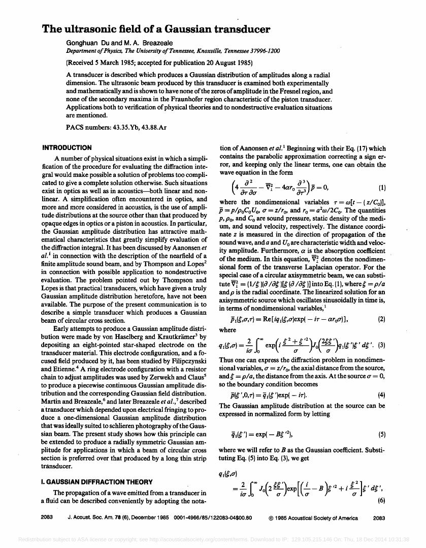
As a basis for the solution, we shall assume the system of coordinates represented in Fig. 1. The electfie field produced by the differential element dS = p dp do) is given as
dE = [ Q ( t )/rra 2 ]p dp dc• [(1/R 2)]. (9)
From Eq. (9) one obtains thez component of the electric field to be
dEz = [ TQ (t )/rra2R 3]p dp d•, (10)
where a is the radius of the electrode on the back of the
piezoelectric crystal and Q (t) is the charge on the electrode. Here, T represents the thickness of the crystal.
According to Fig. 1, we have the following geometrical relation: R 2 = ta +,o 2 _ 2rp cos 4 sin 0. Substituting this relationship into Eq. { 10} and integrating over the area of the electrode, we get the total electric field at the point of obser- vation to be
d• p2 )3/2 ß rra 2 (t a q- - 2pr cos •b sin 0
(11) Upon integration with regard to p and using the geometric relation sin 0 = p'/r, cos 0 -- T/r, and r 2 = p'2 q- T 2, we get
rra 2 [(b 2 q- •- 2) __ • 2 COS 2 • ] [ 1 -- 2• COS • q- (b 2 q- •- 2)]1/2 ' (12)
where b = T/a, • = p'/a, and p' is the radial coordinate on the surface of the transducer.
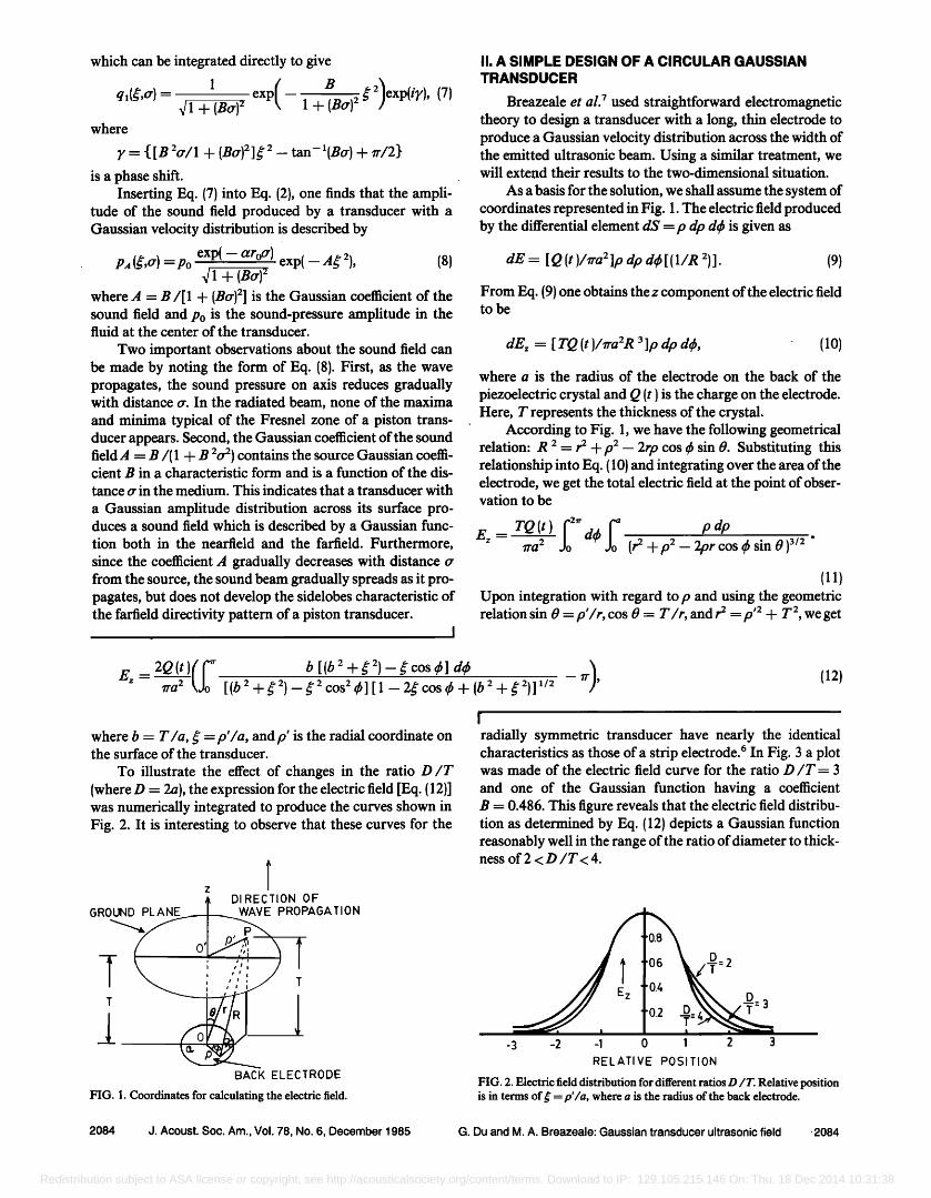
To illustrate the effect of changes in the ratio D/T {where D = 2a), the expression for the electric field [Eq. {12)] was numerically integrated to produce the curves shown in Fig. 2. It is interesting to observe that these curves for the
4• DIRECTION OF GROUND PLANE / WAVE PROPAGATION
i
BACK ELECTRODE
FIG. 1. Coordinates for calculating the electric field.
I
radially symmetric transducer have nearly the identical characteristics as those of' a strip electrode. 6 In Fig. 3 a plot was made of' the electric field curve for the ratio D/T = 3
and one of the Gaussian function having a coefficient B = 0.486. This figure reveals that the electric field distribu- tion as determined by Eq. (12) depicts a Gaussian function reasonably well in the range of the ratio of diameter to thick- ness of' 2 < D/T < 4.
z -3 -2 -1
'0.8
=2
ß 0.• D: 3
o 1 2 3
RELATIVE POSITION
FIG. 2. Electric field distribution for different ratios D/T. Relative position is in terms of g = p'/a, where a is the radius of the back electrode.
2084 J. Acoust. Soc. Am., Vol. 78, No. 6, December 1985 G. Du and M. A. Breazeale: Gaussian transducer ultrasonic field ,2084
Redistribution subject to ASA license or copyright; see http://acousticalsociety.org/content/terms. Download to IP: 129.105.215.146 On: Thu, 18 Dec 2014 10:31:38
••N GAUSSIAN / tO.8 • FUNCTION
: .
-3 -2 -1 0 1 RELATIVE POSITION
FIG. 3. Comparison of the electric field for D/T = 3 and the Gaussian func- tion.
III. EXPERIMENTAL RESULTS
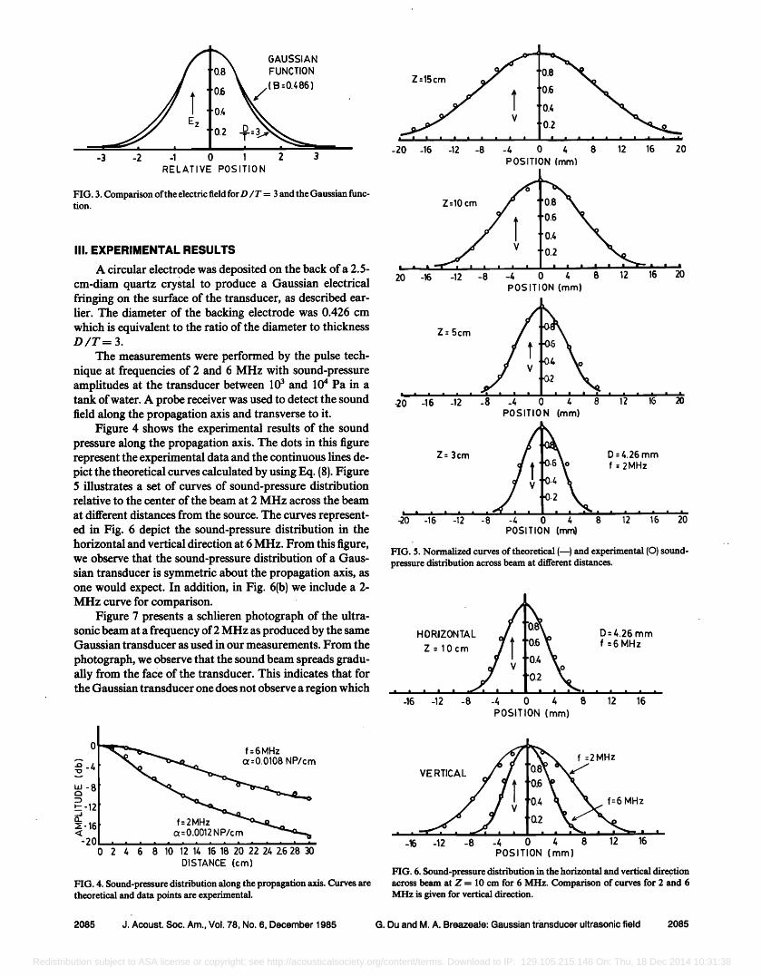
A circular electrode was deposited on the back of a 2.5- cm-diam quartz crystal to produce a Gaussian electrical fringing on the surface of the transducer, as described ear- lier. The diameter of the backing electrode was 0.426 cm which is equivalent to the ratio of the diameter to thickness D/T=3.
The measurements were performed by the pulse tech- nique at frequencies of 2 and 6 MHz with sound-pressure amplitudes at the transducer between 10 3 and 10 4 Pa in a tank of water. A probe receiver was used to detect the sound field along the propagation axis and transverse to it.
Figure 4 shows the experimental results of the sound pressure along the propagation axis. The dots in this figure represent the experimental data and the continuous lines de- pict the theoretical curves calculated by using Eq. (8). Figure 5 illustrates a set of curves of sound-pressure distribution relative to the center of the beam at 2 MHz across the beam
at different distances from the source. The curves represent- ed in Fig. 6 depict the sound-pressure distribution in the horizontal and vertical direction at 6 MHz. From this figure, we observe that the sound-pressure distribution of a Gaus- sian transducer is symmetric about the propagation axis, as one would expect. In addition, in Fig. 6(b) we include a 2- MHz curve for comparison.
Figure 7 presents a schlieren photograph of the ultra- sonic beam at a frequency of 2 MHz as produced by the same Gaussian transducer as used in our measurements. From the
photograph, we observe that the sound beam spreads gradu- ally from the face of the transducer. This indicates that for the Gaussian transducer one does not observe a region which
0 f: 6 MHz • -4 c•:0.0108 NP/cm
uJ-8
•--12
a_ f=2MHz •:-16 •: c•- 0.0012 NP/cm
-20 0 2 4 6 8 10 12 14 16 18 20 22 24 Z628 30
DISTANCE (cm)
FIG. 4. Sound-pressure distribution along the propagation axis. Curves are theoretical and data points are experimental.
-20 -16 -12 -8
'0.8 '0.6
'0.4
I ß ß ß ß ß
-4 0 4 8 12 16 20
POSITION
I '"f I I I I I '
-16 -12 -8 -4 POSIT
Z - 5cm
'0.8
'0.6
0.4
'02
ON (ram)
.06
.(12, , ,•, . -20 -1•) -1• -$ -4 0 4 8 1• 1• 20
POSITION (ram)
D = 4.26 mm
f - 2MHz
ß i ß ß ß
POSITION {ram)
Z= 3cm
FIG. 5. Normalized curves of theoretical (--) and experimental (¸) sound- pressure distribution across beam at different distances.
HORIZONTAL Z=10cm
-12 -8 -4 0 4 B 12 16
POSITION (mm)
'0.8; D = 4.26 mm '0.6 f = 6 MHz
'0 2
MHz
VERTICAL
ß "•'"" ß m•"l I , , ß ß ß "', ß ß •'-' ' -16 -12 -8 -4 0 4 8 12 16
POSITION (mm)
FIG. 6. Sound-pressure distribution in the horizontal and vertical dire9tion across beam at Z = 10 cm for 6 MHz. Comparison of curves for 2 and 6 MHz is given for vertical direction.
2085 J. Acoust. Soc. Am., Vol. 78, No. 6, December 1985 G. Du and M. A. Breazeale: Gaussian transducer ultrasonic field 2085
Redistribution subject to ASA license or copyright; see http://acousticalsociety.org/content/terms. Download to IP: 129.105.215.146 On: Thu, 18 Dec 2014 10:31:38
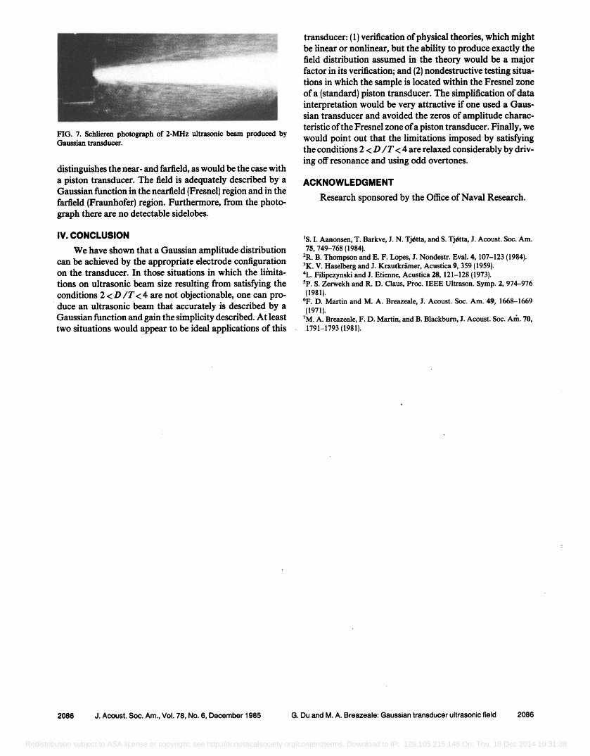
FIG. 7. Schlieren photograph of 2-MHz ultrasonic beam produced by Gaussian transducer.
distinguishes the near- and farfield, as would be the case with a piston transducer. The field is adequately described by a Gaussian function in the nearfield (Fresnel) region and in the farfield (Fraunhofer) region. Furthermore, from the photo- graph there are no detectable sidelobes.
IV. CONCLUSION
We have shown that a Gaussian amplitude distribution can be achieved by the appropriate electrode configuration on the transducer. In those situations in which the limita-
tions on ultrasonic beam size resulting from satisfying the conditions 2 < D/T< 4 are not objectionable, one can pro- duce an ultrasonic beam that accurately is described by a Gaussian function and gain the simplicity described. At least two situations would appear to be ideal applications of this
transducer: (1) verification of physical theories, which might be linear or nonlinear, but the ability to produce exactly the field distribution assumed in the theory would be a major factor in its verification; and (2) nondestructive testing situa- tions in which the sample is located within the Fresnel zone of a (standard) piston transducer. The simplification of data interpretation would be very attractive if one used a Gaus- sian transducer and avoided the zeros of amplitude charac- teristic of the Fresnel zone of a piston transducer. Finally, we would point out that the limitations imposed by satisfying the conditions 2 < D/T< 4 are relaxed considerably by driv- ing off resonance and using odd overtones.
ACKNOWLEDGMENT
Research sponsored by the Office of Naval Research.
•S. I. Aanonsen, T. Barkve, J. N. Tj•tta, and S. Tj•tta, J. Acoust. Soc. Am. 75, 749-768 (1984).
2R. B. Thompson and E. F. Lopes, J. Nondestr. Eval. 4, 107-123 (1984). 3K. V. Haselberg and J. Krautkriimer, Acustica 9, 359 (1959). 4L. Filipczynski and J. Etienne, Acustica 28, 121-128 (1973). 5p. S. Zerwekh and R. D. Claus, Proc. IEEE Ultrason. Symp. 2, 974-976 (1981).
6F. D. Martin and M. A. Breazeale, J. Acoust. Soc. Am. 49, 1668-1669 (1971).
?M. A. Breazeale, F. D. Martin, and B. Blackburn, J. Acoust. Soc. Arh. 70, 1791-1793(1981).
2086 J. Acoust. Soc. Am., Vol. 78, No. 6, December 1985 G. Du and M. A. Breazeale: Gaussian transducer ultrasonic field 2086
Redistribution subject to ASA license or copyright; see http://acousticalsociety.org/content/terms. Download to IP: 129.105.215.146 On: Thu, 18 Dec 2014 10:31:38


![Presentation P3121 english V5-01 [Kompatibilitätsmodus] · • Wireless LAN Ultrasonic Search Units • Coupling wedge. • Ultrasonic transducer • RF transducer cable. Hardness](https://img.pdfslide.net/doc/110x75/5baf026609d3f22d458ba836/presentation-p3121-english-v5-01-kompatibilitaetsmodus-wireless-lan-ultrasonic.jpg)