Embed Size (px)
Citation preview
THE UNIVERSITY OF ALBERTA
ROCK SLOPE S T A B I L I T Y ANALYSIS USING MORGENSTERN-PRICE METHOD
BY
STEVE TAN
A REPORT SUBMITTED TO THE FACULTY OF GRADUATE STUDIES
AND RESEARCH I N PARTIAL FULFILLMENT OF THE REQUIREMENTS FOR THE DEGREE OF MASTER OF ENGINEERING
DEPARTMENT OF C I V I L ENGINEERING EDMONTON, ALBERTA
A P R I L , 1975
THE UNIVERSITY OF ALBERTA
FACULTY OF GRADUATE STUDIES & RESEARCH
The undersigned c e r t i f i e s t h a t he has read, and recommends
t o t h e Facu l t y of Graduate Studies and Research f o r acceptance,
a r e p o r t e n t i t l e d ROCK SLOPE STABILITY ANALYSIS USING MORGENSTERN-
PRICE METHOD, submit ted by Steve Tan i n p a r t i a l f u l f i l l m e n t o f
t he requirements f o r t h e degree o f Master o f Engineering.
Superv isor
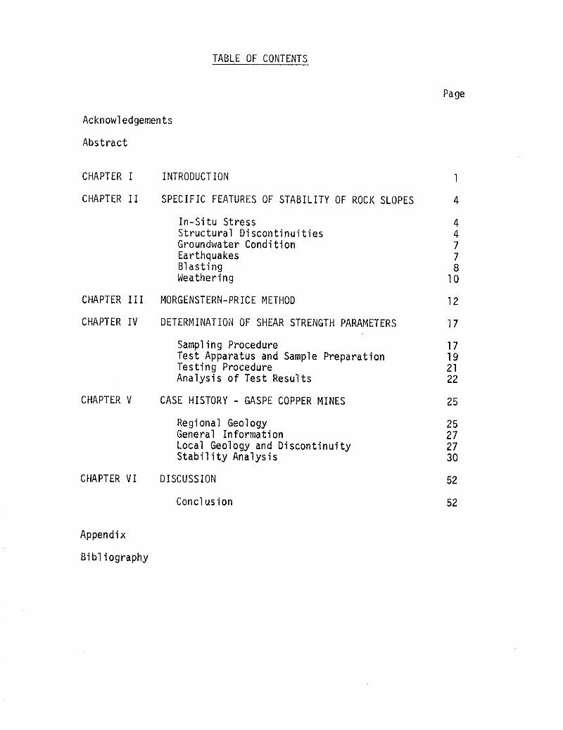
TABLE OF CONTENTS
Page
Acknowledgements
Abstract
CHAPTER I INTRODUCTION 1
CHAPTER I1 SPECIFIC FEATURES OF STABILITY OF ROCK SLOPES 4
In-Situ Stress Structural Discontinuities Groundwater Condition Earthquakes Blasting Weathering
CHAPTER I11 MORGENSTERN-PRICE METHOD
CHAPTER IV DETERMINATION OF SHEAR STRENGTH PARAMETERS 17
Sampling Procedure 17 Test Apparatus and Sample Preparation 19 Testing Procedure 21 Analysis of Test Results 22
CHAPTER V CASE HISTORY - GASPE COPPER MINES 25
Regional Geology General Information Local Geology and Discontinuity S t ab i l i t y Analysis
CHAPTER VI DISCUSSION 52
Conclusion 52
Appendix
Bi bl iography
ACKNOWLEDGEMENTS
The au thor wishes t o acknowledge, w i t h many thanks,
Dr. Z . E isens te in under whose superv is ion t h i s r e p o r t was prepared.
H is t o p i c suggest ion, d i r e c t i o n and encouragement du r i ng the work
a re deeply apprec iated.
The author i s a l s o indebted t o D r . S. Thomson and
Dr. N. R. Morgenstern f o r t h e i r h e l p f u l guidance i n t he computer
analyses w i thou t which the i n v e s t i g a t i o n cou ld n o t be complete.
Apprec ia t ion i s extended t o S. Law f o r h i s h e l p f u l d i s -
cuss ions on var ious aspects o f the r e p o r t .
F i n a l l y , t he au thor wishes t o thank N. Seniuk f o r her
e d i t o r i a l ass is tance and the t y p i n g o f t h i s repo r t .
ABSTRACT
With the increas ing s i z e and depth o f the open p i t mines being
constructed f o r the immediate f u t u r e , the importance o f the s t a b i l i t y
o f the p i t w a l l can n o t be overemphasized. A m isca l cu la t i on i n the
performance o f the w a l l may mean loss o f 1 i f e , damage t o p rope r t y and
may produce severe f i n a n c i a l consequences. The recogn i t i on o f t h i s
f a c t together w i t h today 's techno log ica l knowhow i n rock mechanics has
r e s u l t e d i n a more economic and s a f e t y conscious open p i t design. Sys-
temat ic eva lua t i on o f the s t a b i l i t y o f the p i t s has become a p a r t o f the
mine maintenance r o u t i n e work.
The Gaspe Copper Mine, a who l ly owned subs id ia ry o f Noranda
Mines Ltd., i s an open p i t opera t ion designed t o go t o a maximum depth
o f 1,000 f e e t w i t h a proposed 430 slope angle. Present development i s
a t the 250 f o o t l e v e l . It i s feared t h a t when min ing progresses t o a
much greater depth, a s l i d e would occur t a k i n g w i t h i t the smel ter and
t h e adjacent bu i l d ings .
The r e p o r t deals w i t h the s t a b i l i t y i n v e s t i g a t i o n o f a c e r t a i n
sec t i on o f the Gaspe Copper Mine 's u l t i m a t e p i t geometry. A t o t a l o f
n ine poss ib le s l i p surfaces were analyzed f i r s t us ing the s imp ler wedge
ana lys i s and then w i t h t h e more exact Morgenstern-Price method. The
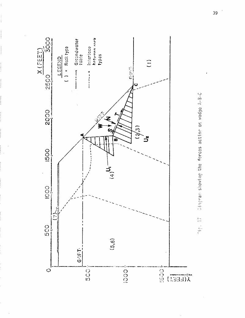
lowest f a c t o r o f s a f e t y ( f o r s l i p surface A-B-C) found i s about 0.5,
i n d i c a t i n g t h a t the slope i s unstable. Analys is o f the same s l i p surface
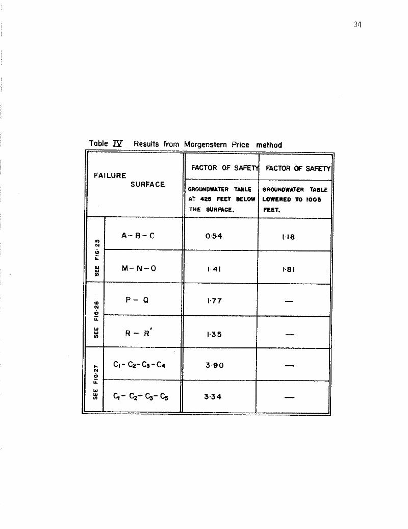
A-8-C was then extended t o a s i t u a t i o n i n which the groundwater l e v e l was
lowered from 425 f e e t t o 1,005 f e e t below t h e surface. The f a c t o r o f
s a f e t y i n t h i s case has r i s e n t o about 1.2, an acceptable cond i t i on .
CHAPTER I
INTRODUCTION -
For years engineers have been c o n s t a n t l y f a c i n g rock slope
s t a b i l i t y problems i n t h e i r des ign work. However, i n s u f f i c i e n t e f f o r t
has been devoted so f a r t o s tudy ing the i n f l u e n t i a l f a c t o r s and t h e
f a i l u r e mechanisms which c o n t r o l the s t a b i l i t y o f these slopes. Often,
t he design c r i t e r i a f o r a p i t w a l l used by the p r a c t i c i n g engineers
were based on past experiences and r u l e o f thumb; i . e . , the s lope angle
i s gene ra l l y taken t o be between 37O and 45O, and the u l t i m a t e angle o f
the s lope i s der ived from some form o f t r i a l and e r r o r d u r i n g the prod-
u c t i o n per iod. A change o f one o r two degrees seems t o cause i n s i g n i f i -
can t e f f e c t s on the economic success o r f a i l u r e o f the p r o j e c t .
I n recent t imes t h e con t i nu ing d e p l e t i o n o f h i g h grade minera l
depos i ts and the vas t increase i n raw ma te r i a l consumption have opened
up a new hor izon f o r the min ing i n d u s t r y . Ore bodies which were consid-
ered uneconomical t o be developed p rev ious l y have now become economical ly
f e a s i b l e . With the advent o f large-volume earthmoving equipment, open
p i t mines a re being planned and operated t o depths and s i zes t h a t were
unheard o f before. As the p i t gets deeper, the angle o f t h e slope begins
t o p l a y an impor tan t r o l e i n t he p r o f i t eve lua t i on o f t he opera t ion .
Brawner (1971) i n d i c a t e s t h a t f o r a p i t 3,000 f e e t deep, an increase o f
one degree i n t he s lope angle represents an a d d i t i o n a l excavat ion cos t o f
5 t o 15 m i l l i o n d o l l a r s . It i s t he re fo re obvious t h a t s u b s t a n t i a l savings
can be made i f one u t i l i z e s t h e maximum slope angle w i thou t j eopa rd i z i ng
t h e s a f e t y o f t he people work ing i n t he v i c i n i t y .
Al though the cos ts d i c t a t e t he con t i nua t i on o r t he deser t ion o f
an opera t ion , the s a f e t y o f the men and the equipment working i n the
area remains t o be the f i r s t concern i n any open p i t design. I n
eng ineer ing the degree o f safeness o f a c u t wa l l i s expressed by a term
known as t h e " f a c t o r o f sa fe ty " . I t i s de f ined as the r a t i o o f t h e sum
o f a l l forces which may be ~ n o b i l i z e d f o r r e s i s t i n g f a i l u r e t o the sum
t o t a l o f a l l the d i s t u r b i n g forces, o r as the r a t i o o f a v a i l a b l e t o
mob i l i zed shear s t rength . A f a c t o r o f s a f e t y l e s s than one i n d i c a t e s
t h a t an unstable cond i t i on e x i s t s and t h a t f a i l u r e i s l i k e l y t o occur.
On the o the r hand, a f a c t o r o f s a f e t y greater than one imp l i es t h a t the
p o s s i b i l i t y o f a major catastrophe i s n o t l i k e l y t o happen. The h igher
the value, the l esse r i s the chance o f a s l i d e .
The eva lua t ion o f the f a c t o r o f s a f e t y invo lves e labora te pro-
cedures. With the a i d o f the modern computer techno log ica l advances.
these c a l c u l a t i o n s can now be performed i n g reater d e t a i l . The r e l i a b i l -
i t y o f the ana lys i s depends a great deal on the a b i l i t y t o e s t a b l i s h the
opera t ive f i e l d shear s t reng th and t o some ex ten t the method employed i n
the ana lys is , as we l l as the a b i l i t y t o est imate the ground water l e v e l
cond i t ions .
Many slope s t a b i l i t y cons idera t ions have been pub1 ished i n the
l i t e r a t u r e s ince Terzaghi (1962) ca l cu la ted the c r i t i c a l he igh t o f a
v e r t i c a l w a l l c u t through s o l i d rock. Numerous methods were introduced,
a l l o f which make use o f the p r i n c i p l e developed i n s o i l mechanics. Among
the more w ide l y used methods o f s t a b i l i t y ana lys is on hard rock are the
wedge ana lys i s and the Morgenstern-Price method, the l a t t e r being t h e more
exact method as w i l l become obvious i n subsequent chapters.
The purpose o f t h i s r e p o r t i s t o i n v e s t i g a t e t h e performance
o f a c e r t a i n sec t i on o f the Gaspe Copper Mines p i t w a l l , as the min ing
a c t i v i t y progresses t o i t s maximum depth, us ing both the Morgenstern-Price
and the simpler Wedge Methods of s t a b i l i t y analysis. Several potential
s l i p surfaces were considered and the r e su l t s and recommendations are
discussed in Chapter VI.
I t has been demonstrated by Muller e t a1 (1970), Goodman e t
a1 (1968), and many others t ha t f a i l u r e s i n rock slopes tend t o be con-
fined t o s t ructural d i scont inu i t i es , hence any rational s t a b i l i t y analysis
requires a sound knowledge of the geological environmental fac tors of the
area under investigation. A description of the d i f fe ren t fac tors which
influence the s t a b i l i t y of the slope and the various measures which can
be taken t o ensure a more s t ab l e condition are presented in Chapter 11.
A br ief review of the Morgenstern-Price Method i s incorporated in Chapter
111. Chapter IV describes the sampling and tes t ing procedures followed
t o obtain the shear strength parameters of the mater ia l ( s ) involved in the
study. Chapter V looks a t the regional and local geology surrounding the
Gaspe Copper Mines and the spec i f ic features needed for a r e a l i s t i c con-
s iderat ion of a possible s l i d e .
CHAPTER I1
SPECIFIC FEATURES OF STABILITY OF ROCK SLOPES
In a study of the s t a b i l i t y of rock slopes, there i s a
variety of features which are relevant to the accuracy of the analysis.
Among the more important ones a r e :
(1 ) In-situ s t r e s s - Contrary to the common belief tha t the ver t ical
s t r e s s i s the only dominant factor in rock mass, high horizontal
s t r e s s several times tha t of the vertical has been recorded (Hast
1967). This abnormally high horizontal s t r e s s coupled w i t h the
quick response of rock t o unloading, such as a p i t or s t r ipping
of overburden, causes bulging and tension cracks around the peri-
phery of the excavation; thus reducing the shear strength of the rock.
( 2 ) Structural discontinuit ies - This includes the j o in t s , the f a u l t s
and f au l t zones, and the planes of weakness such as contact planes
and a l te ra t ion zones. Unlike fau l t s and f a u l t zones, jo ints often
occur in s e t s of two t ha t are a t a r ight angle t o one another. Be-
cause of the closely spaced nature of these j o in t s , the pattern i s
ra ther d i f f i c u l t t o detect with the various geophysical exploration
tools during the planning stage. Hence, trenches are required in
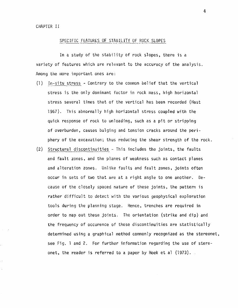
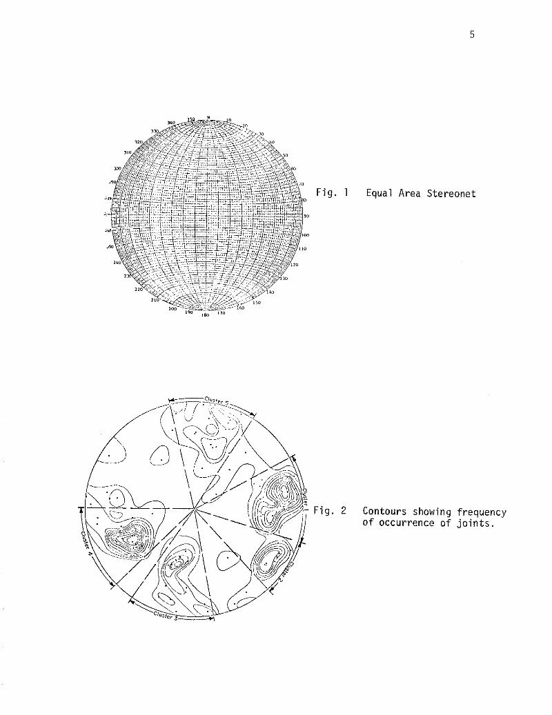
order to map o u t these jo in t s . The orientation ( s t r i ke and d ip) and
the frequency of occurence of these discont inui t ies are s t a t i s t i c a l l y
determined using a graphical method commonly recognized as the stereonet,
see Fig. 1 and 2 . For fur ther information regarding the use of s te re -
onet, the reader i s referred t o a paper by Hoek e t a1 (1973).
F i g . 1 Equal Area Stereonet
F i g . 2 Contours showing frequency o f occurrence o f j o i n t s .
S t r u c t u r a l d i s c o n t i n u i t i e s a f f e c t the s t a b i l i t y o f rock slopes i n
two ways:
(a ) Shear s t rengths a long the plane o f d i s c o n t i n u i t y a re gene ra l l y
lower; consequent ly, t he f a c t o r o f s a f e t y i s lower. The reduc-
t i o n i n shear s t reng th may be the r e s u l t o f a number o f c ircum-
stances :
( i ) l o s s o f cohesion due t o t he f a c t t h a t the m a t e r i a l i s f r a c t u r e d
( i i ) t h e presence o f the opening a l lows the water t o f l o w i n r e s u l t i n g i n a reduc t i on o f the e f f e c t i v e normal s t ress and the shear s t reng th
( i i i ) a l t e r a t i o n products f i l l i n g t he openings a c t as some form o f 1 u b r i c a n t
( i v ) l a r g e displacement as i n the case o f a f a u l t reduces the shear ing res i s tance from peak t o res idua l , and/or
( v ) a combinat ion o f the above.
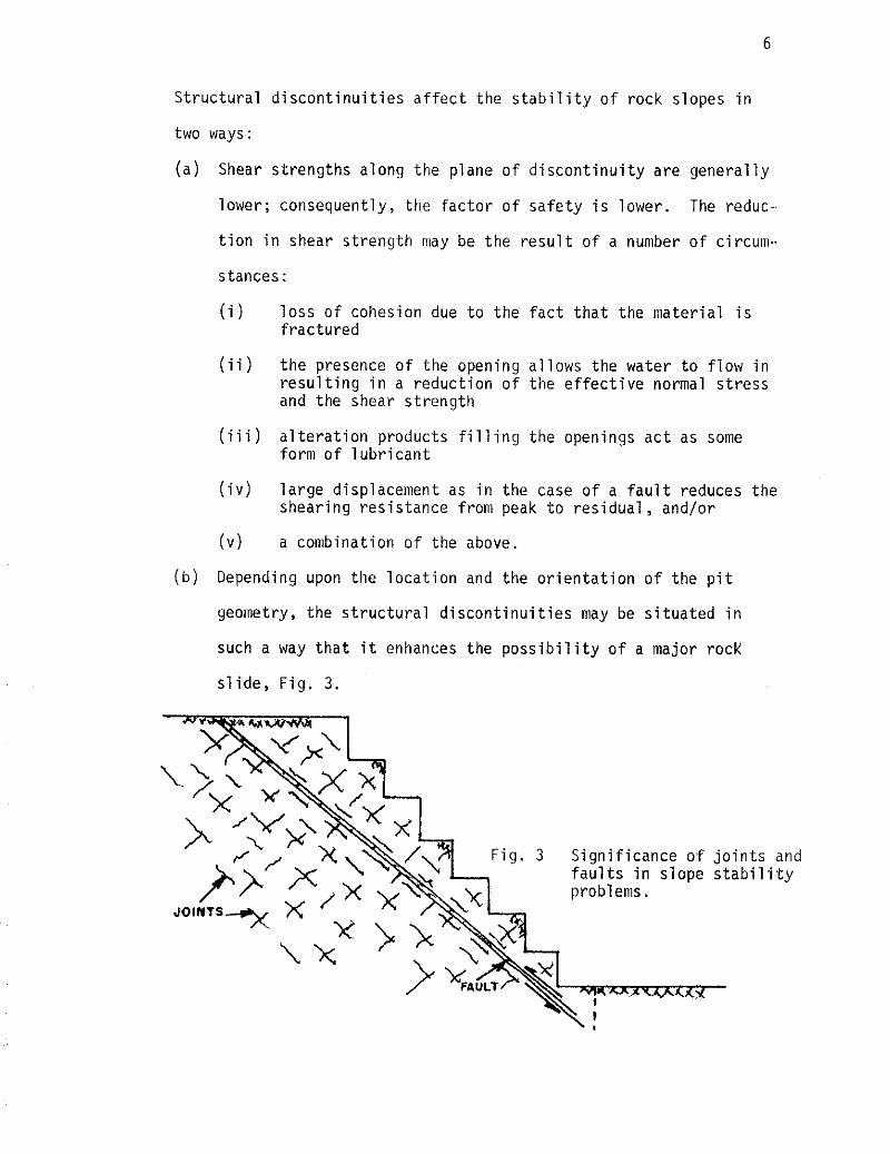
( b ) Depending upon the l o c a t i o n and the o r i e n t a t i o n o f the p i t
geometry, t he s t r u c t u r a l d i s c o n t i n u i t i e s may be s i t u a t e d i n
such a way t h a t i t enhances the p o s s i b i l i t y o f a major rock
s l i d e , F ig . 3.
F ig . 3 S ign i f i cance o f j o i n t s and f a u l t s i n s lope s t a b i l i t y
( 3 ) Groundwater c o n d i t i o n - Water pressure reduces the e f f e c t i v e
normal s t ress and lowers the shearing s t reng th accord ing ly
(Morgenstern 1970). Chemical a l t e r a t i o n due t o the presence o f
water a l s o lowers the s t rength . Furthermore, excessive water
i n f l u x i n t o the p i t i s a nuisance t o the min ing opera t ion and can
become very c o s t l y i f n o t p rope r l y cor rec ted . Therefore, a complete
p i c t u r e o f whether t h e mine i s l oca ted i n a reg iona l groundwater
discharge area o r recharge area o r i n some in te rmed ia te area i s
c e r t a i n l y advantageous, s ince w i thou t i t erroneous conclus ions can
be drawn w i t h respect t o the s u i t a b i l i t y o f drainage f a c i l i t i e s and
o the r remedial measures (Patton e t a1 1970).
( 4 ) Earthquakes - Many o f the earthquake-induced l ands l i des have s e r i -
ous l y a f f e c t e d mining operat ions i n one way o r another a l though no
ac tua l slope f a i l u r e i n open p i t mines du r ing earthquakes has been
repor ted i n the l i t e r a t u r e . I n the l a s t ten years s tud ies i n t o the
i n f l uence on s t a b i l i t y were c a r r i e d ou t by i n v e s t i g a t o r s l i k e Seed
(1970), Goodman e t a1 (1966), and o thers . Laboratory t e s t models
such as a b lock r e s t i n g on an i n c l i n e d plane subjected t o a se r ies
o f acce le ra t i on pulses s imulate the ac tua l behaviour o f rock o r s o i l
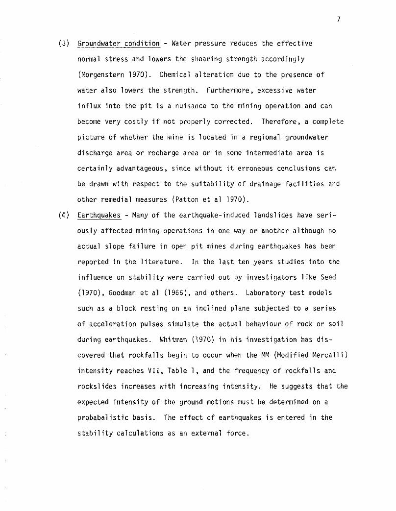
du r i ng earthquakes. Whitman (1970) i n h i s i n v e s t i g a t i o n has d i s -
covered t h a t r o c k f a l l s begin t o occur when the MM (Mod i f ied M e r c a l l i )
i n t e n s i t y reaches V I I , Table 1, and the frequency o f r o c k f a l l s and
rocks l i des increases w i t h increas ing i n t e n s i t y . He suggests t h a t the
expected i n t e n s i t y o f t h e ground motions must be determined on a
p r o b a b a l i s t i c basis . The e f f e c t o f earthquakes i s entered i n the
s t a b i l i t y c a l c u l a t i o n s as an ex terna l fo rce .
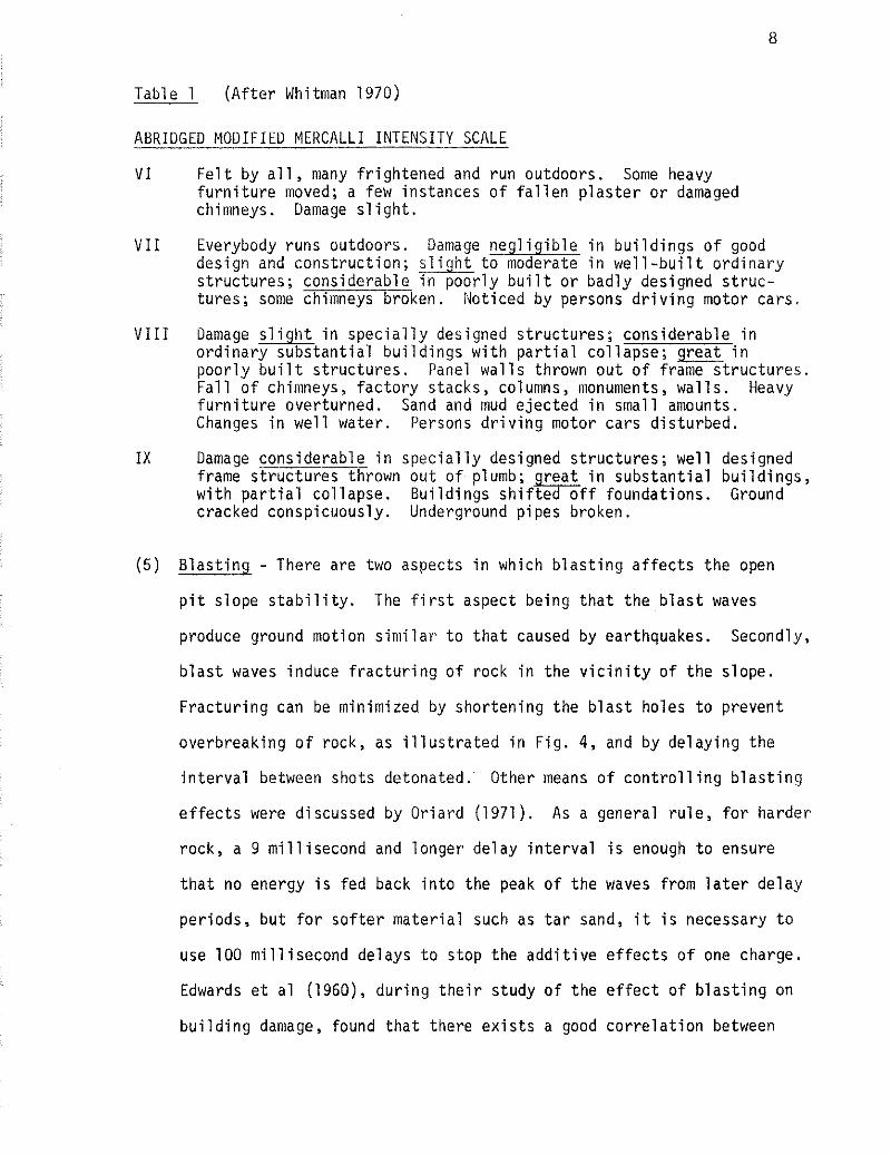
Table 1 ( A f t e r Whitman 1970)
ABRIDGED MODIFIED MERCALLI INTENSITY SCALE
V I F e l t by a l l , many f r i gh tened and run outdoors. Some heavy f u r n i t u r e moved; a few instances o f f a l l e n p l a s t e r o r damaged chimneys. Damage s l i g h t .
V I I Everybody runs outdoors. Damage n e g l i g i b l e i n b u i l d i n g s o f good design and cons t ruc t i on ; s l i g h t t o moderate i n w e l l - b u i l t o r d i n a r y s t ruc tu res ; considerable i n p o o r l y b u i l t o r bad ly designed s t r u c - tures; some chimneys broken. Not iced by persons d r i v i n g motor cars.
V I I I Damage s l i g h t i n s p e c i a l l y designed s t ruc tu res ; considerable i n o r d i n a r y subs tan t i a l b u i l d i n g s w i t h p a r t i a l co l lapse ; great i n p o o r l y b u i l t s t ruc tu res . Panel w a l l s thrown o u t o f frame s t r u c t u r e s . F a l l o f chimneys, f a c t o r y stacks, columns, monuments, w a l l s . Heavy f u r n i t u r e overturned. Sand and mud e jec ted i n smal l amounts. Changes i n w e l l water. Persons d r i v i n g motor cars d is tu rbed.
I X Damage considerable i n s p e c i a l l y designed s t ruc tu res ; we1 1 designed frame s t r u c t u r e s thrown o u t o f plumb; r e a t i n subs tan t i a l b u i l d i n g s , w i t h p a r t i a l co l lapse . Bu i l d i ngs s h i f t e % o f f foundat ions. Ground cracked conspicuously. Underground p ipes broken.
( 5 ) B l a s t i n g - There are two aspects i n which b l a s t i n g a f f e c t s t he open
p i t s lope s t a b i l i t y . The f i r s t aspect being t h a t t he b l a s t waves
produce ground motion s i m i l a r t o t h a t caused by earthquakes. Secondly,
b l a s t waves induce f r a c t u r i n g o f rock i n the v i c i n i t y o f t h e slope.
F r a c t u r i n g can be minimized by shor ten ing the b l a s t ho les t o prevent
overbreaking o f rock, as i l l u s t r a t e d i n F ig . 4, and by de lay ing t h e
i n t e r v a l between shots detonated. Other means o f c o n t r o l l i n g b l a s t i n g
e f f e c t s were discussed by Or ia rd (1971 ) . As a general r u l e , f o r harder
rock, a 9 m i l l i s e c o n d and longer delay i n t e r v a l i s enough t o ensure
t h a t no energy i s f e d back i n t o the peak o f t h e waves from l a t e r de lay
per iods, bu t f o r s o f t e r m a t e r i a l such as t a r sand, i t i s necessary t o
use 100 m i l l i s e c o n d delays t o s top the a d d i t i v e e f f e c t s o f one charge.
Edwards e t a1 (1960), du r i ng t h e i r s tudy o f t he e f f e c t o f b l a s t i n g on
b u i l d i n g damage, found t h a t there e x i s t s a good c o r r e l a t i o n between
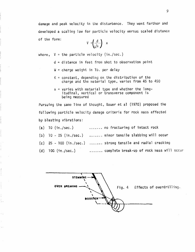
damage and peak v e l o c i t y i n the d is turbance. They went f a r t h e r and
developed a s c a l i n g law f o r p a r t i c l e v e l o c i t y versus scaled d is tance
o f the form:
where, V = t h e p a r t i c l e v e l o c i t y ( i n . / sec . )
d = d is tance i n f e e t from shot t o observat ion p o i n t
W = charge weight i n l b . per delay
K = constant, depending on the d i s t r i b u t i o n o f the charge and the ma te r ia l type, va r i es from 45 t o 450
x = va r ies w i t h ma te r i a l type and whether t h e long- i t u d i n a l , v e r t i c a l o r t ransverse component i s being measured
Pursuing the same l i n e o f thought, Bauer e t a1 (1970) proposed the
f o l l o w i n g p a r t i c l e v e l o c i t y damage c r i t e r i a f o r rock mass a f f e c t e d
by b l a s t i n g v i b r a t i o n s :
(a ) 10 ( in . /sec . ) ....... no f r a c t u r i n g o f i n t a c t rock
(b) 10 - 25 ( in . /sec . ) . ...... minor t e n s i l e s l a b b i n g w i l l occur
( c ) 25 - 100 ( in . /sec . ) . . . . . . . s t rong t e n s i l e and r a d i a l c rack ing
(d) 100 ( in . /sec . ) . . . . . . . complete break-up o f rock mass w i l l occur
OVER BREARING Fig . 4 E f f e c t s o f o v e r d r i l l i n g .
( 6 ) Weathering - D e t e r i o r a t i o n o f rock due t o weathering w i t h i n the
1 i f e span o f a min ing opera t ion i s n o t common. However, there are
cases repor ted i n which newly exposed surfaces o f shale have wea-
thered considerably, l o s i n g much o f t h e i r shear s t reng th i n o n l y
a few months. Shear parameters used i n the ana lys i s o f these cases
must be c a r e f u l l y chosen. A t the present, there are no s a i d r u l e s
on how the shear s t reng th ought t o be selected. Another phenomenon
t h a t has t o be accounted f o r i n a s t a b i l i t y ana lys is i s the change
i n the s t reng th o f rock w i t h increas ing depth. Given the same type
o f rock, the f a r t h e r away from the surface, t h e l esse r the weathering
e f f e c t , hence the greater i t s s t rength w i l l be. It should be noted
t h a t i n each o f the above f a c t o r s , t ime p lays an important r o l e i n
degree o f i n f l uence i n the s t a b i l i t y ca l cu la t i ons . With t h i s i n mind,
perhaps the performance o f a slope should be checked a t regu la r i n t e r -
va l s so t h a t the danger o f a s l i d e due t o an unforeseen cause --
excessive r a i n o r snow, pore pressure bui ld-up, e tc . -- can be r e c t i f i e d .
Forms o f mon i to r ing a p o t e n t i a l s lope f a i l u r e i n open p i t s are des-
c r i b e d by Watt (1970) and Kennedy (1971 ) .
A f t e r t h e warning comes the improvement on the slope. According
t o Golden (1970), s t a b i l i z i n g a slope i s u s u a l l y poss ib le . But c e r t a i n
quest ions must be asked i n o rder t o se lec t the c o r r e c t method o f s t a b i l i z a t i o n .
These a re :
(a ) How much s t a b i l i t y i s requ i red?
(b) How much funding i s a l l o c a t e d f o r the p r o j e c t ?
( c ) What causes the i n s t a b i l i t y ?
(d) For how long i s i t requ i red?
Once these quest ions are answered, i t takes l i t t l e e f f o r t t o
decide which of the available methods of stabilization to use, i.e.:
(a) mechanical strengthening
(b) change shape of slope
(c) drainage (Hoek et a1 1970)
CHAPTER 111
MORGENSTERN-PRICE METHOD
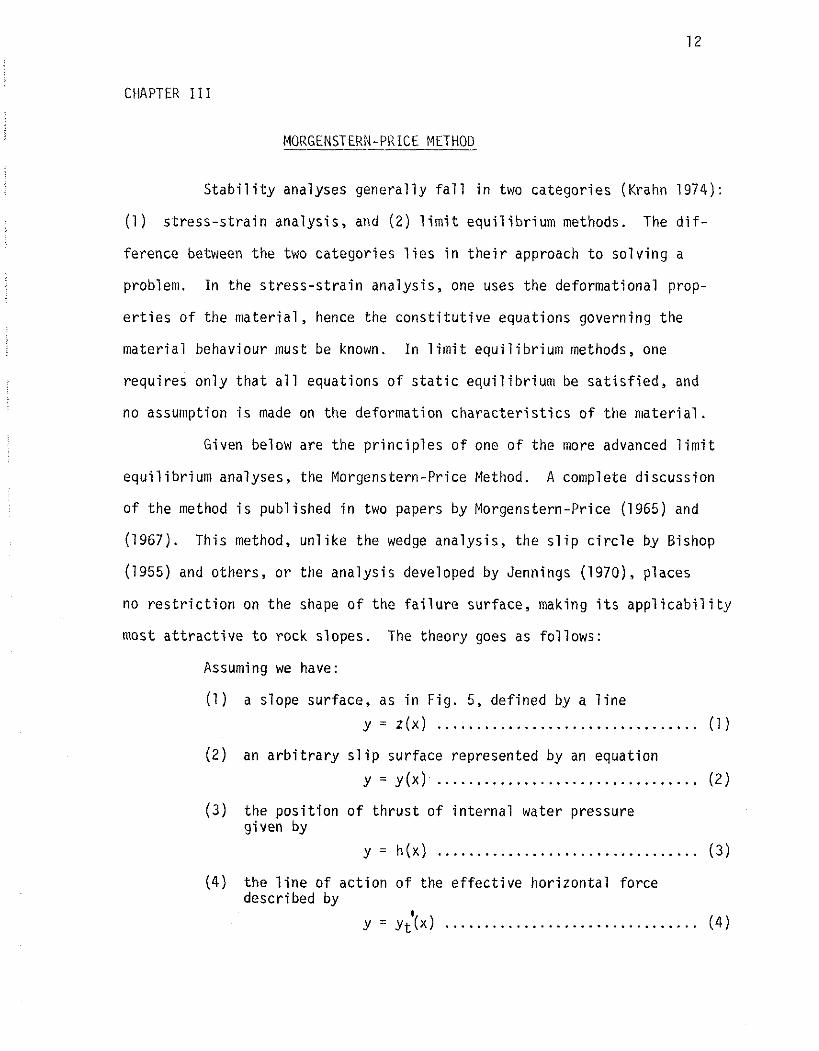
S t a b i l i t y analyses genera l l y fa1 1 i n two ca tegor ies (Krahn 1974):
(1 ) s t r e s s - s t r a i n analys is , and ( 2 ) l i m i t e q u i l i b r i u m methods. The d i f -
ference between t h e two ca tegor ies l i e s i n t h e i r approach t o s o l v i n g a
problem. I n the s t r e s s - s t r a i n ana lys is , one uses the deformat ional prop-
e r t i e s o f the m a t e r i a l , hence the c o n s t i t u t i v e equat ions governing the
ma te r ia l behaviour must be known. I n l i m i t e q u i l i b r i u m methods, one
requ i res o n l y t h a t a l l equat ions o f s t a t i c e q u i l i b r i u m be s a t i s f i e d , and
no assumption i s made on the deformation c h a r a c t e r i s t i c s o f t h e m a t e r i a l .
Given below are t h e p r i n c i p l e s o f one o f the more advanced l i m i t
e q u i l i b r i u m analyses, the Morgenstern-Price Method. A complete d iscussion
o f the method i s publ ished i n two papers by Morgenstern-Price (1965) and
(1967). This method, u n l i k e the wedge ana lys is , t h e s l i p c i r c l e by Bishop
(1955) and others, o r the ana lys i s developed by Jennings (1970), places
no r e s t r i c t i o n on t h e shape o f the f a i l u r e surface, making i t s a p p l i c a b i l i t y
most a t t r a c t i v e t o rock slopes. The theory goes as fo l lows:
Assuming we have:
(1 ) a slope surface, as i n F ig. 5, de f ined by a l i n e
y = z (x ) ................................. (1)
( 2 ) an a r b i t r a r y s l i p surface represented by an equat ion
(3 ) the p o s i t i o n o f t h r u s t o f i n t e r n a l water pressure g iven by
y = h(x) ................................. ( 3 )
(4 ) t h e l i n e o f a c t i o n o f the e f f e c t i v e h o r i z o n t a l fo rce described by
y=Y;(x) ................................ ( 4 )
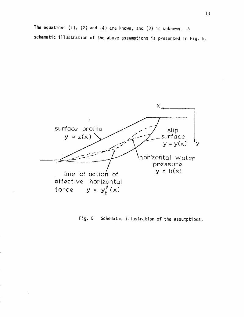
The equat ions ( I ) , (2) and (4 ) a re known, and (3 ) i s unknown. A
schematic i l l u s t r a t i o n o f the above assumptions i s presented i n F ig. 5 .
s u r f a c ~ profi le
horizontal W Q ~ Q ~
pressure
line of action of y = h(x)
e t f ~ c t l v ~ horizontal f o r c e I y = yt ( X I
Fig . 5 Schematic i l l u s t r a t i o n o f the assumptions.
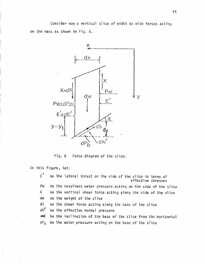
Consider now a ver t ical s l i c e of width dx with forces acting
on the mass as shown in Fig. 6 .
Fig. 6 Force diagram of the s l i c e .
I n t h i s f igure , l e t :
be the la te ra l thrust on the side of the s l i c e i n terms of e f fec t ive s t resses
be the resul tant water pressure acting on the s ide of the s l i c e
be the ver t ical shear force acting along the side of the s l i c e
be the weight of the s l i c e
be the shear force acting along the base of the s l i c e
be the e f fec t ive normal pressure
be the incl inat ion of the base of the s l i c e from the horizontal
be the water pressure acting on the base of the s l i c e
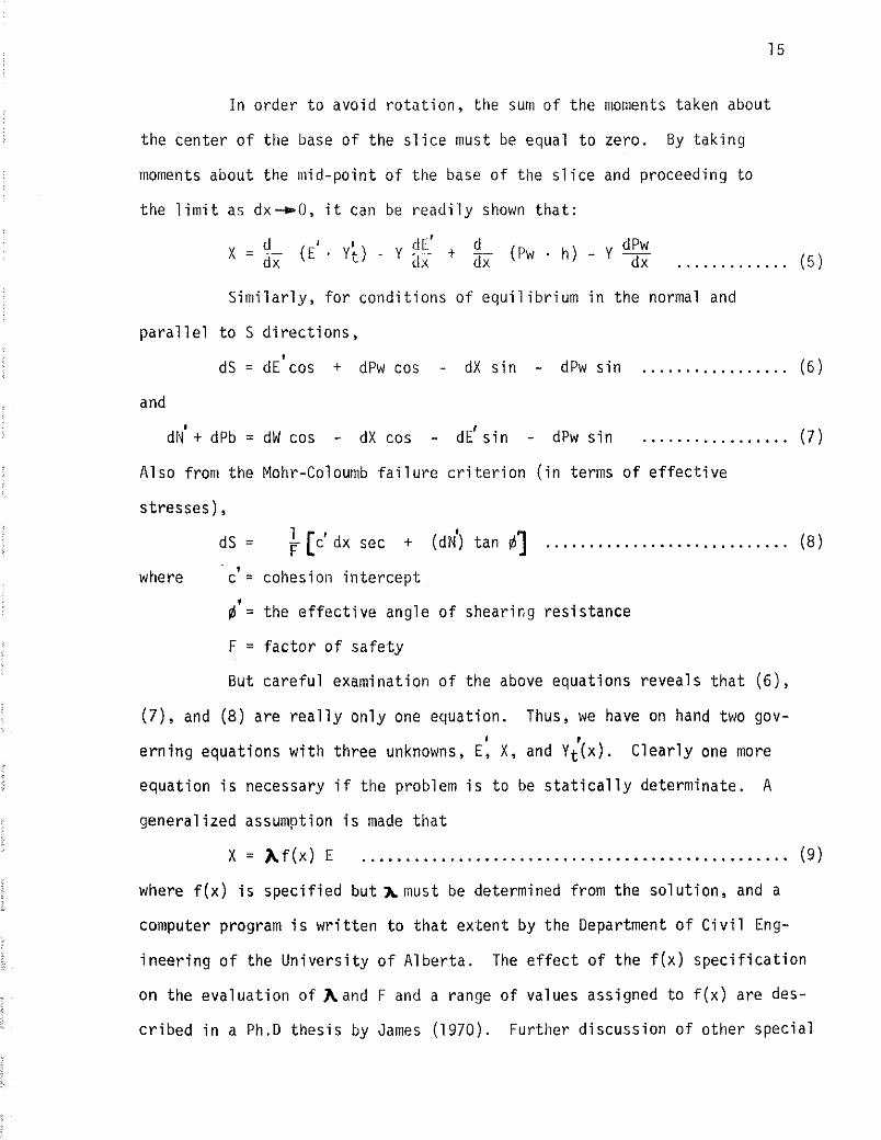
I n o rder t o avo id r o t a t i o n , the sum o f the nionients taken about
the center o f the base o f the s l i c e must be equal t o zero. By t a k i n g
moments about the mid-po in t o f the base o f the s l i c e and proceeding t o
the l i m i t as dx-0, i t can be r e a d i l y shown t h a t :
S i m i l a r l y , f o r cond i t i ons o f e q u i l i b r i u m i n the normal and
p a r a l l e l t o S d i r e c t i o n s ,
dS = d ~ ' c o s + dPw cos - dX s i n - dPw s i n ................. ( 6 )
and
d d + dPb = dW cos - dX cos - d ~ ' s i n - dPw s i n ................. (7 )
Also from the Mohr-Coloumb f a i l u r e c r i t e r i o n ( i n terms o f e f f e c t i v e
s t resses) ,
dS = [c' dx sec + (dd) tan $3 ............................ (8)
where c' = cohesion i n t e r c e p t
@ ' = the e f f e c t i v e angle o f shearing res is tance
F = f a c t o r o f s a f e t y
But c a r e f u l examinat ion o f the above equat ions revea ls t h a t ( 6 ) ,
(7) , and ( 8 ) are r e a l l y o n l y one equat ion. Thus, we have on hand two gov- * t
e r n i n g equat ions w i t h th ree unknowns, E, X , and Yt(x). C l e a r l y one more
equat ion i s necessary i f the problem i s t o be s t a t i c a l l y determinate. A
genera l i zed assumption i s made t h a t
X = A f ( x ) E ................................................. (9)
where f ( x ) i s s p e c i f i e d b u t h n u s t be determined from the so lu t i on , and a
computer program i s w r i t t e n t o t h a t ex ten t by the Department o f C i v i l Eng-
i n e e r i n g of the U n i v e r s i t y o f A lbe r ta . The e f f e c t o f t h e f ( x ) s p e c i f i c a t i o n
on the eva lua t i on o f h a n d F and a range o f values assigned t o f ( x ) are des-
c r i b e d i n a Ph.D t h e s i s by James (1970). Fur ther d iscuss ion o f o ther spec ia l
assumptions re la t ing X and E forces (Bishop 1955, Janbu 1954) o r the l i ne
of horizontal th rus t (Kenney 1956) i s beyond the scope of t h i s paper.
CHAPTER I V
DETERMINATION OF SHEAR STRENGTH PARAMETERS
The determinat ion o f the shear s t reng th o f the rock d iscon-
t i n u i t i e s invo lves th ree phases: (1) o b t a i n i n g samples, (2 ) p repar ing
t e s t specimens, and ( 3 ) shear t e s t i n g t o de r i ve a s t rength value nec-
essary f o r s t a b i l i t y ana lys i s .
Sampling Procedure
As was mentioned before, f a i l u r e i n rock slopes tends t o be
conf ined t o s t r u c t u r a l d i s c o n t i n u i t i e s . So the f i r s t s tep i s t o assess
the governing t ype (s ) o f d i s c o n t i n u i t i e s o f the area i n quest ion. This
i s accomplished by an extensive s t r u c t u r a l mapping. Upon recogn iz ing
the c o n t r o l l i n g features, a k i n e m a t i c a l l y poss ib le s l i d i n g mechanism i s
determined. Then i t i s poss ib le t o s e l e c t t h e s i t e s i n which represent-
a t i v e samples o f the c r i t i c a l d i s c o n t i n u i t i e s could be taken f o r labora-
t o r y t e s t i n g . Before the sample i s removed from i t s o r i g i n a l p o s i t i o n ,
t h e s t r i k e , d ip , d i r e c t i o n o f shear, l oca t i on , and e l e v a t i o n should be
marked c l e a r l y on each specimen and recorded i n the f i e l d book f o r f u t u r e
references.
Samplins o f rock i s achieved i n one o f two ways:
(1 ) b lock sample, which u t i l i z e s no spec ia l equipment o the r than
a p i c k and shovel. This method i s easy t o perform and cos ts considerably
l e s s than cor ing .
(2 ) cored sample i s obta ined w i t h a masonry d r i l l co r i ng around
the des i rab le d i s c o n t i n u i t i e s . The method i s adaptable t o both s u r f a c i a l
cond i t i ons and deep boreholes. I t can be app l ied t o any spec ia l d i r e c t i o n s ,
p laces, and depths. A p i c t u r e o f the por tab le c o r i n g u n i t developed by t h e

Department o f C i v i l Eng ineer ing, t h e U n i v e r s i t y o f A l b e r t a , i s shown i n
F i g . 7. Fo r complete d e s c r i p t i o n and s p e c i f i c a t i o n o f t h i s machine, t h e
reader i s r e f e r r e d t o S tewar t (1974).
F i g . 7 Photograph o f d r i l l i n g u n i t used. ( f r o m S tewar t 1974)
A l though c o r i n g i s v e r y v e r s a t i l e i n many senses, t h e method
does have severe problems a s s o c i a t e d w i t h anchor ing and c o r e r e c o v e r y
when h i g h l y f r a c t u r e d sample s i t e s a r e encountered. Furthermore, pene t -
r a t i o n o f t h e d r i l l i n t o h a r d igneous r o c k s sometimes p r e s e n t s a prob lem.
Ra te o f advance as low as 1 inch /hour has been r e p o r t e d (S tewar t 1974) .
A t t h i s r a t e , i t i m p l i e s t h a t o n l y one sample can be recovered p e r day.
S i n c e t ime and money are t h e c o n t r o l l i n g f a c t o r s i n any p r o j e c t , b l o c k
samp l ing i s a lways p r e f e r r e d o v e r c o r i n g .
Whether a core o r a b lock, the samples would f a l l apar t r e a d i l y .
Every precaut ion must be taken t o preserve the specimen and the d i scon t i nu -
i t y i n t a c t . It was found t h a t by wrapping the samples i n rubber sheet
foam, the breakage due t o handl ing and t ranspor ta t i on back t o the labora-
t o r y was v i r t u a l l y e l im ina ted.
For the p a r t i c u l a r mine under i n v e s t i g a t i o n , Gaspe Copper Mines,
s ince the rock was h i g h l y weathered and f rac tu red , on l y t h e b lock sampling
method was employed. The l a r g e s t specimen obta ined was about 4 " x 6" .
Test Apparatus and Sample Preparat ion
Based on experience, the d i r e c t shear method was chosen. Tes t ing
was t o be performed on t h e small and l a rge shearing machine w i t h a constant
s t r a i n r a t e (0.048 inches per minute) under var ious normal pressures ranging
2 from 0.4 t o 21 kg./cm. . The s izes o f the specimens selected f o r t h e ex-
periment were t o be 2" x 2 " , 4 " x 5 " , and 12" x 12".
The small shearing machine, F ig . 8, was designed and b u i l t a t
t h e U n i v e r s i t y o f A lber ta . It cons is ts o f (1) a dead weight l e v e r , ( 2 ) a
shear box, ( 3 ) an e l e c t r i c motor, (4) a gear box, and ( 5 ) two LVDT's ( l i n e a r
v a r i a b l e d i f f e r e n t i a l t ransducer) and a three hundred pound lead c e l l . The
machine handles sample s izes 2" x 2" and 4" x 5 " and i s capable o f d e l i v e r i n g
up t o a maximum o f 2 tons shear fo rce . The shear load i s app l i ed t o the
lower h a l f o f the shear box through a gear box cha in d r i v e n assembly powered
by an e l e c t r i c motor, wh i l e t h e upper h a l f i s he ld i n p lace w i t h a load c e l l
a t tached t o i t . Th is produces a r e l a t i v e motion between the two halves o f
t h e shear box along a preconceived plane. The res is tance o f the upper h a l f
t o t h e motion i s measured by the l oad c e l l i n terms o f vo l tage and i s l a t e r
conver ted t o an equ iva len t shear fo rce . Te f l on s t r i p s are used t o separate
t h e two halves and along the guides so as t o minimize the machine f r i c t i o n
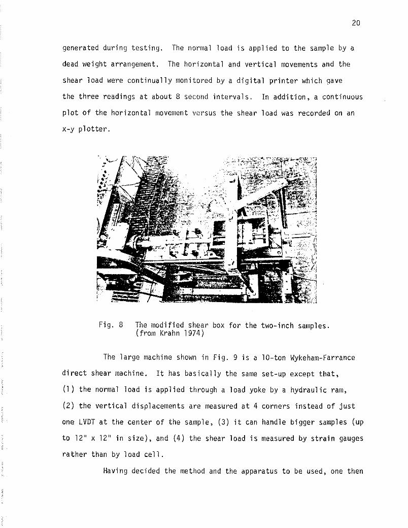
generated du r ing t e s t i n g . The normal load i s app l i ed t o the sample by a
dead weight arrangement. The ho r i zon ta l and v e r t i c a l movements and the
shear load were c o n t i n u a l l y monitored by a d i g i t a l p r i n t e r which gave
the th ree readings a t about 8 second i n t e r v a l s . I n a d d i t i o n , a cont inuous
p l o t of the h o r i z o n t a l movement versus t h e shear load was recorded on an
x-y p l o t t e r .
F i g . 8 The modi f ied shear box f o r the two- inch samples. ( from Krahn 1974)
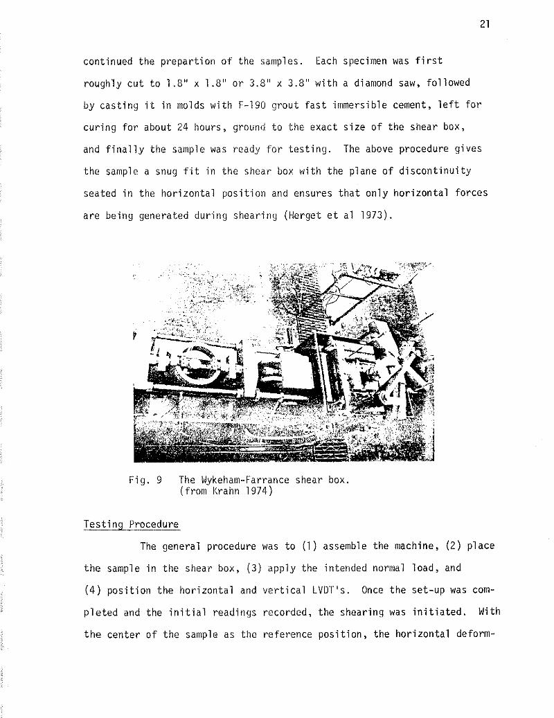
The l a r g e machine shown i n F ig . 9 i s a 10-ton Wykeham-Farrance
d i r e c t shear machine. It has b a s i c a l l y the same set-up except t ha t ,
(1 ) t h e normal load i s app l i ed through a load yoke by a hyd rau l i c ram,
( 2 ) t h e v e r t i c a l displacements are measured a t 4 corners ins tead o f j u s t
one LVDT a t t h e center o f the sample, ( 3 ) i t can handle b igger samples (up
t o 12" x 12" i n s i ze ) , and (4) the shear load i s measured by s t r a i n gauges
r a t h e r than by 1 oad c e l l . Having decided the method and the apparatus t o be used, one then
cont inued the p repa r t i on o f the samples. Each specimen was f i r s t
roughly c u t t o 1 .8" x 1.8" o r 3.8" x 3.8" w i t h a diamond saw, fo l lowed
by cas t i ng i t i n molds w i t h F-190 grout f a s t immersible cement, l e f t f o r
cu r i ng f o r about 24 hours, ground t o the exact s i z e o f the shear box,
and f i n a l l y the sample was ready f o r t e s t i n g . The above procedure g ives
the sample a snug f i t i n t h e shear box w i t h the plane o f d i s c o n t i n u i t y
seated i n the ho r i zon ta l p o s i t i o n and ensures t h a t on l y h o r i z o n t a l forces
are being generated dur ing shearing (Herget e t a1 1973).
F ig . 9 The Wykeham-Farrance shear box. ( f rom Krahn 1974)
Tes t i ng Procedure -
The general procedure was t o (1) assemble the machine, ( 2 ) p lace
t h e sample i n t h e shear box, ( 3 ) app ly the intended normal load, and
( 4 ) p o s i t i o n t h e ho r i zon ta l and v e r t i c a l LVDT's. Once t h e set-up was com-
p l e t e d and the i n i t i a l readings recorded, the shearing was i n i t i a t e d . With
t h e center o f t h e sample as the reference pos i t i on , the ho r i zon ta l deform-
a t i o n cont inued u n t i l a displacement o f 0.25" was reached. A t t h i s p o i n t ,
the machine was stopped and reversed. Shearing cont inued i n the o the r
d i r e c t i o n u n t i l i t had reached 0.25" past i t s reference p o i n t . The motion
was then stopped again and brought back t o the o r i g i n a l p o s i t i o n . This
c o n s t i t u t e s one complete t e s t i n g cyc le under one normal load. The pro-
cedure was repeated on the same specimen under var ious i nc reas ing normal
1 oads.
Analys is o f Test Resul ts
Each specimen was tes ted under 4 o r 5 d i f f e r e n t normal loads.
With each normal load, a shear load versus ho r i zon ta l displacement curve
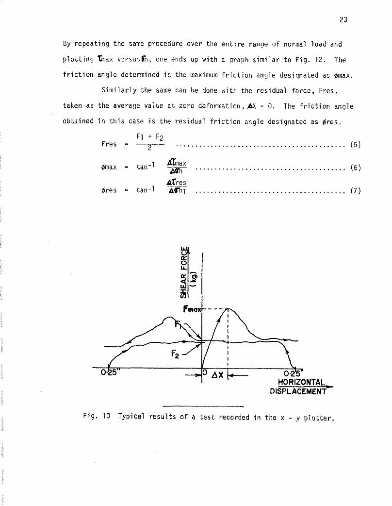
and a v e r t i c a l versus h o r i z o n t a l displacement p l o t were obtained. From
the i n fo rma t ion fu rn ished by these curves and w i t h proper f r i c t i o n cor -
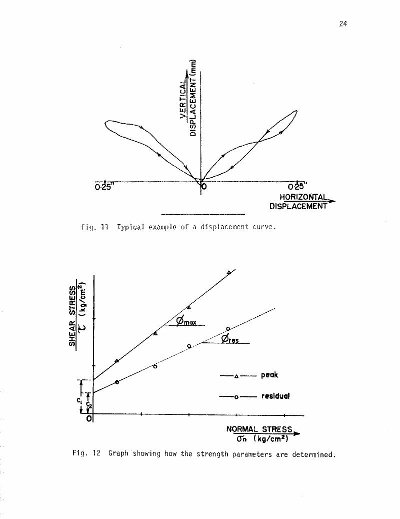
r e c t i o n , a t h i r d graph - shear s t ress versus normal s t ress - was constructed
f o r each specimen. I n t h i s t h i r d graph, the angle o f i n c l i n a t i o n o f t h e
l i n e represents the f r i c t i o n angle o f the mat te r and the y - i n t e r c e p t rep re -
sents the apparent cohesion o f the m a t e r i a l .
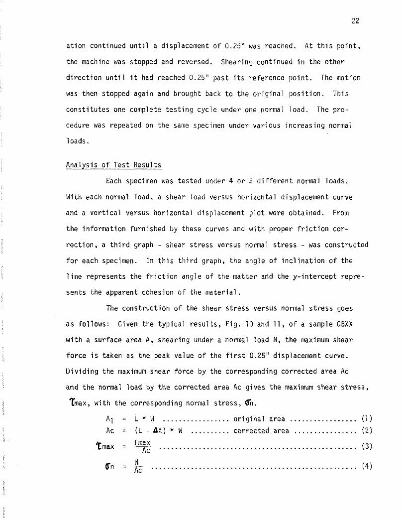
The cons t ruc t i on o f the shear s t ress versus normal s t r e s s goes
as fo l l ows : Given the t y p i c a l r e s u l t s , F ig . 10 and 11, o f a sample GBXX
w i t h a sur face area A, shearing under a normal l oad N, the maximum shear
f o r c e i s taken as the peak value o f the f i r s t 0.25" displacement curve.
D i v i d i n g the maximum shear fo rce by the corresponding cor rec ted area Ac
and t h e normal l oad by t h e co r rec ted area Ac g ives t h e maximum shear s t ress ,
%ax, w i t h the corresponding normal s t ress , bn.
A1 = L * U ................. o r i g i n a l area ................. (1)
Ac = (L - AX) * W .......... cor rec ted area ................ (2 )
Fmax Tmax = -- Ac ................................................ ( 3 )
By r e p e a t i n g t h e same p rocedure o v e r t h e e n t i r e range o f normal l o a d and
p l o t t i n g %:lax v z r s u s t h , one ends up w i t h a graph s i m i l a r t o F i g . 12 . The
f r i c t i o n a n g l e de te rm ined i s t h e maximum f r i c t i o n a n g l e d e s i g n a t e d as dmax.
S i m i l a r l y t h e same can be done w i t h t h e r e s i d u a l f o r c e , F res ,
t a k e n as t h e average v a l u e a t z e r o de fo rmat ion , AX = 0. The f r i c t i o n a n g l e
o b t a i n e d i n t h i s case i s t h e r e s i d u a l f r i c t i o n a n g l e d e s i g n a t e d as Bres .
F1 + F2 F res = -- ............................................ 2 ( 5 )
F i g . 10 T y p i c a l r e s u l t s o f a t e s t reco rded i n t h e x - y p l o t t e r .
F i g . 11 Typical example of a displaceolent curve
- A- peak
- o- reslduol
NORMAL STRESS Cn (kg/cm*)
Fig. 12 Graph showing how t h e s t r eng th parameters a r e determined.
CHAPTER V
CASE HISTORY - GASPE COPPER MINES
Regional G e o l o g ~
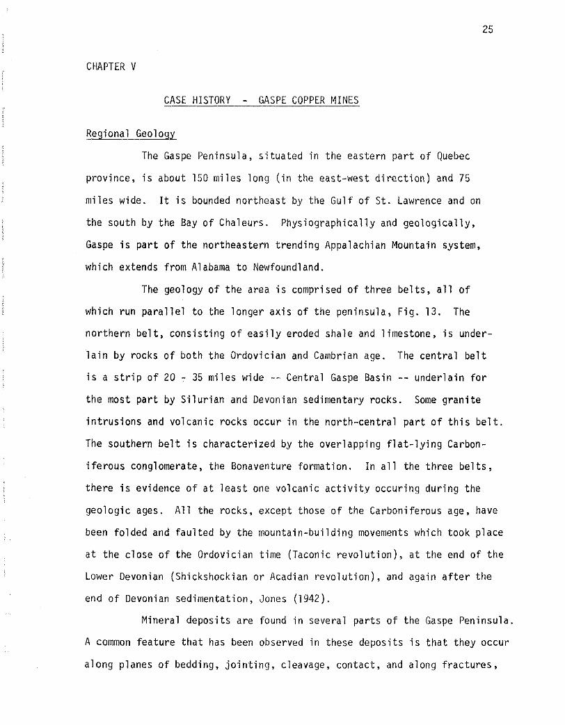
The Gaspe Peninsula, s i t u a t e d i n the eastern p a r t o f Quebec
province, i s about 150 m i les long ( i n the east-west d i r e c t i o n ) and 75
m i les wide. It i s bounded nor theas t by the Gu l f o f S t . Lawrence and on
the south by the Bay o f Chaleurs. Phys iograph ica l l y and g e o l o g i c a l l y ,
Gaspe i s p a r t o f t h e nor theastern t rend ing Appalachian Mountain system,
which extends from Alabama t o Newfoundland.
The geology o f t h e area i s comprised o f th ree b e l t s , a l l o f
which run p a r a l l e l t o the longer a x i s o f the peninsula, F ig. 13. The
no r the rn b e l t , cons i s t i ng o f e a s i l y eroded shale and l imestone, i s under-
l a i n by rocks o f bo th the Ordovician and Cambrian age. The c e n t r a l b e l t
i s a s t r i p o f 20 - 35 m i l es wide - - Central Gaspe Basin -- under la in f o r
the most p a r t by S i l u r i a n and Devonian sedimentary rocks. Some g r a n i t e
i n t r u s i o n s and vo lcan ic rocks occur i n the no r th -cen t ra l p a r t o f t h i s b e l t .
The southern be1 t i s charac ter ized by the over lapping f l a t - l y i n g Carbon-
i f e rous conglomerate, the Bonaventure format ion. I n a1 1 the th ree be1 t s ,
t he re i s evidence o f a t l e a s t one volcanic a c t i v i t y occur ing du r ing the
geo log ic ages. A l l the rocks, except those o f the Carboniferous age, have
been fo lded and f a u l t e d by the mounta in-bui ld ing movements which took p lace
a t t h e c lose o f the Ordovician t ime (Taconic r e v o l u t i o n ) , a t the end o f t h e
Lower Devonian (Shickshockian o r Acadian r e v o l u t i o n ) , and again a f t e r t h e
end o f Devonian sedimentat ion, Jones (1942).
Minera l depos i ts a re found i n several p a r t s o f the Gaspe Peninsula.
A common fea tu re t h a t has been observed i n these deposi ts i s t h a t they occur
a long planes o f bedding, j o i n t i n g , cleavage, contac t , and along f rac tu res ,
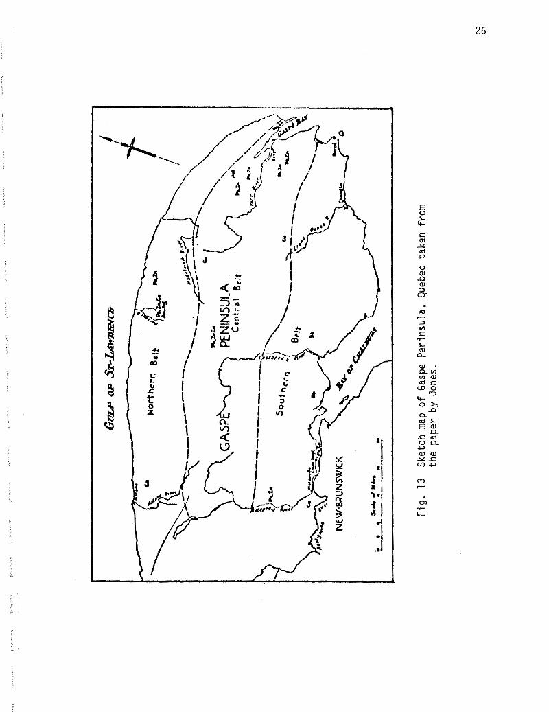
Fig
. 13
S
ketc
h m
ap
of
Gas
pe P
enin
sula
, Q
uebe
c ta
ken
from
th
e pa
per
by J
ones
.
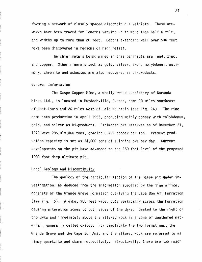
forming a network of closely spaced discontinuous ve in le t s . These net-
works have been traced for lengths varying up to more than half a mile,
and widths u p t o more than 20 f ee t . Depths extending well over 500 f e e t
have been discovered in regions of high r e l i e f .
The chief metals being mined in t h i s peninsula are lead, zinc,
and copper. Other minerals such a s gold, s i l v e r , i ron, molybdenum, an t i -
mony, chromite and asbestos are a l so recovered as bi-products.
General Information
The Gaspe Copper Mine, a wholly owned subsidiary of Noranda
Mines L t d . , i s located in Murdochville, Quebec, some 20 miles southeast
of Mont-Louis and 20 miles west of Bald Mountain (see Fig. 14 ) . The mine
came in to production in April 1955, producing mainly copper with molybdenum,
gold, and s i l v e r a s bi-products. Estimated ore reserves a s of December 31,
1972 were 285,018,000 tons , grading 0.49% copper per ton. Present prod-
uction capacity i s set a s 34,000 tons of sulphide ore per day. Current
developments on the p i t have advanced t o the 250 foot level of the proposed
1000 foot deep ultimate p i t .
Local Geology and Discontinuity
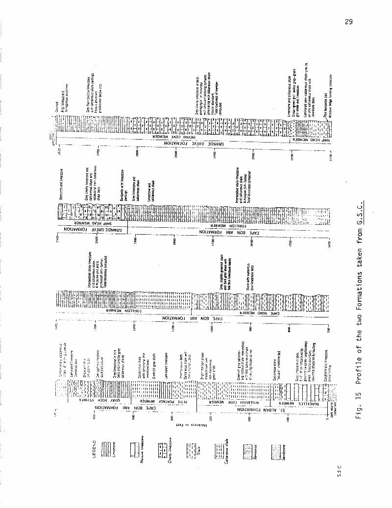
The geology of the par t icular section of the Gaspe p i t under in-
vest igat ion, as deduced from the information supplied by the mine o f f i c e ,
cons i s t s of the Grande Greve Formation overlying the Cape Bon Ami Formation
(see Fig. 15) . A dyke, 900 f e e t wide, cuts ver t i ca l ly across the Formation
causing a l t e r a t i on zones t o b o t h sides of the dyke. Seated t o the r i gh t of
t he dyke and immediately above the a l te red rock i s a zone of weathered mat-
e r i a l , generally cal led oxides. For simplicity the two Formations, the
Grande Greve and the Cape Bon Ami, and the a l tered rock a re referred t o as
1 imey quar tz i te and skarn respectively. Structural ly , there are two major
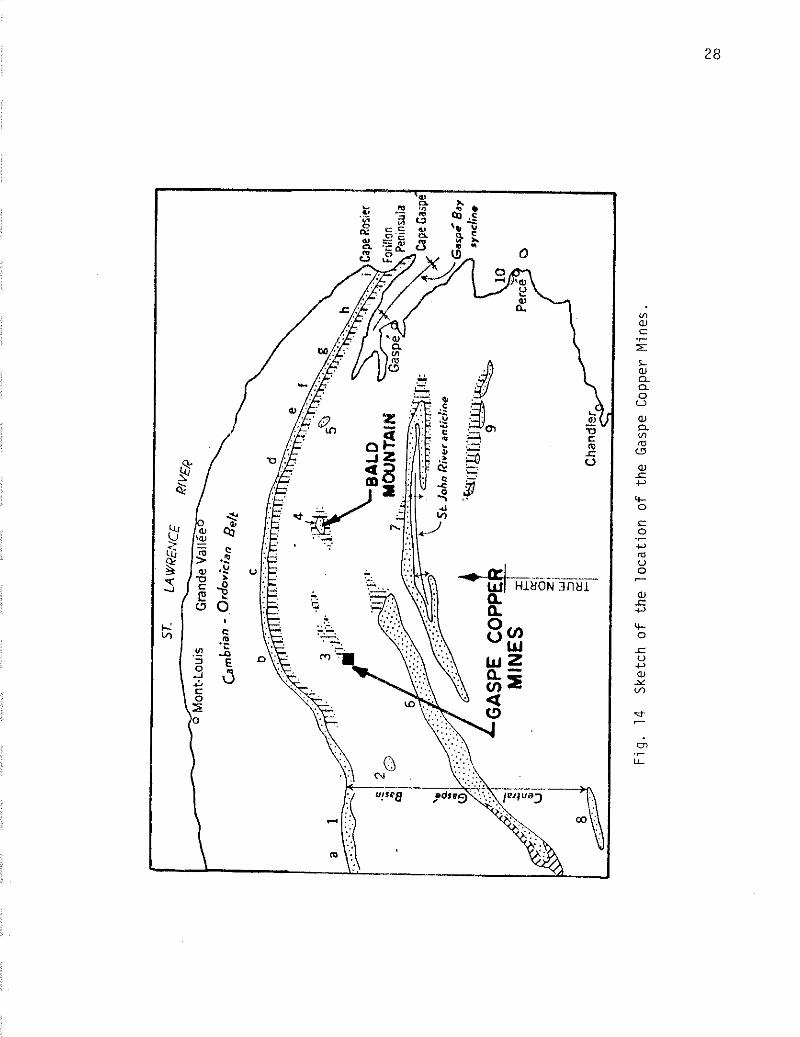
Fig
. 14
S
ketc
h o
f th
e lo
cati
on
o
f th
e G
aspe
Cop
per
Min
es.
I", la sr\,u*i,y,
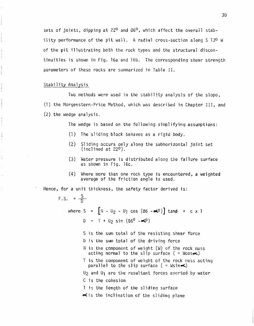
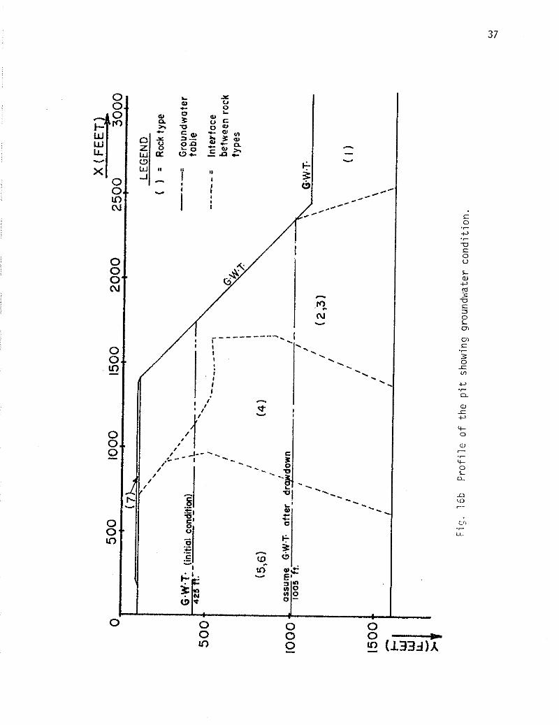
sets o f j o i n t s , d ipp ing a t 2Z0 and GbO, which a f f e c t the o v e r a l l stab-
i l i t y performance o f t h e p i t w a l l . A r a d i a l c ross-sec t ion a long S 130 W
o f t h e p i t i l l u s t r a t i n g bo th t h e rock types and the s t r u c t u r a l discon-
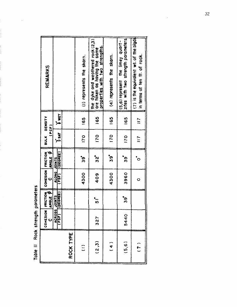
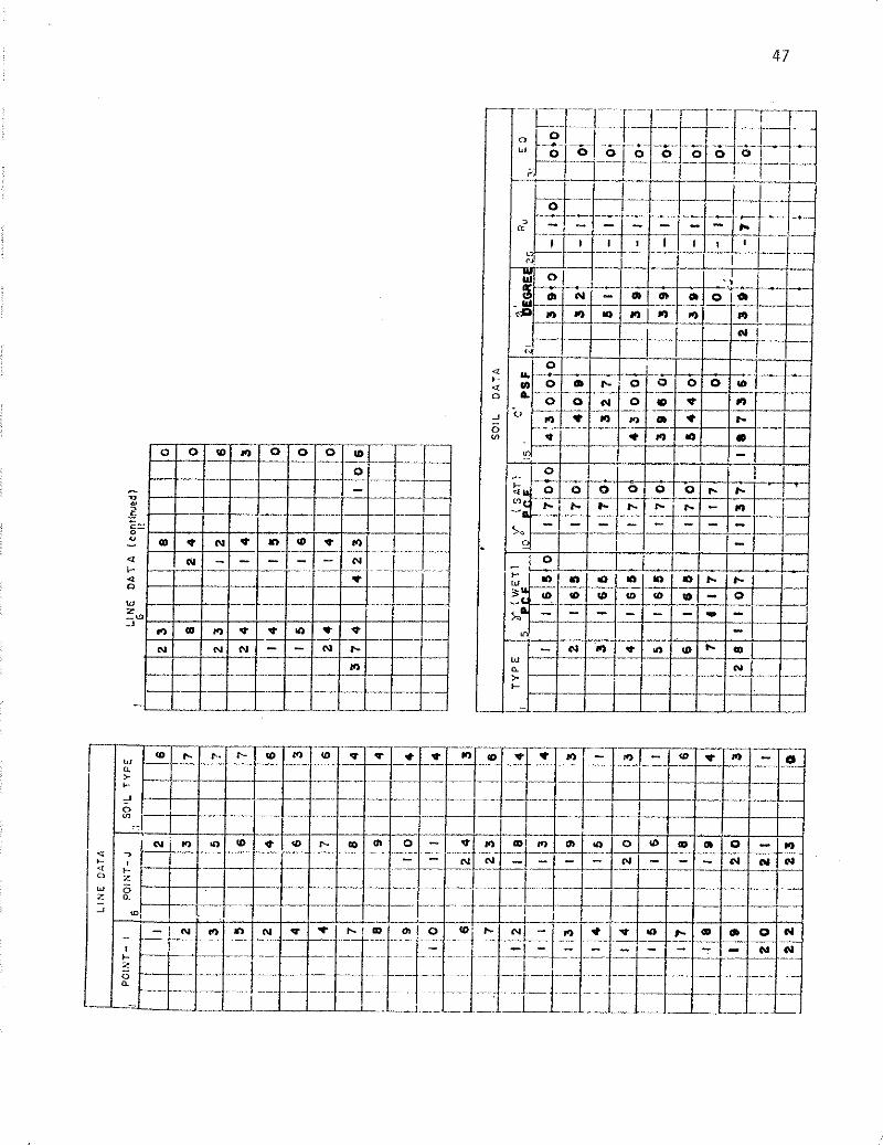
t i n u i t i e s i s shown i n F ig . 16a and 16b. The corresponding shear s t reng th
parameters o f these rocks are summarized i n Table 11.
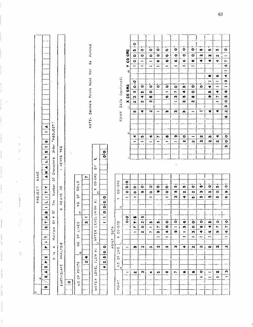
S t a b i l i t y Analys is
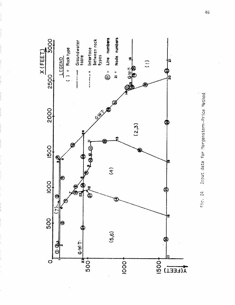
Two methods were used i n the s t a b i l i t y ana lys i s o f the slope,
(1) the Morgenstern-Price Method, which was described i n Chapter 111, and
(2) the wedge ana lys is .
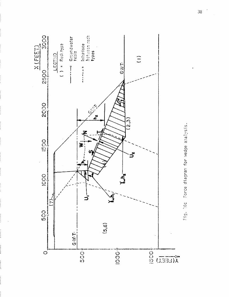
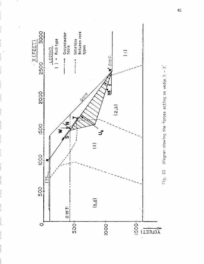
The wedge i s based on the f o l l o w i n g s i m p l i f y i n g assumptions:
(1 ) The s l i d i n g b lock behaves as a r i g i d body.
(2 ) S l i d i n g occurs o n l y along t h e subhor izonta l j o i n t se t ( i n c l i n e d a t 22O).
( 3 ) Water pressure i s d i s t r i b u t e d along t h e f a i l u r e sur face as shown i n F ig. 16c.
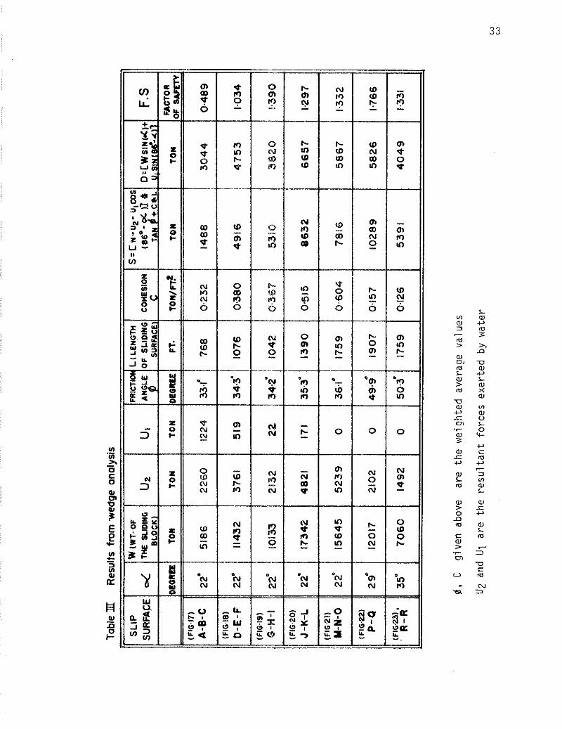
( 4 ) Where more than one rock type i s encountered, a weighted average o f the f r i c t i o n angle i s used.
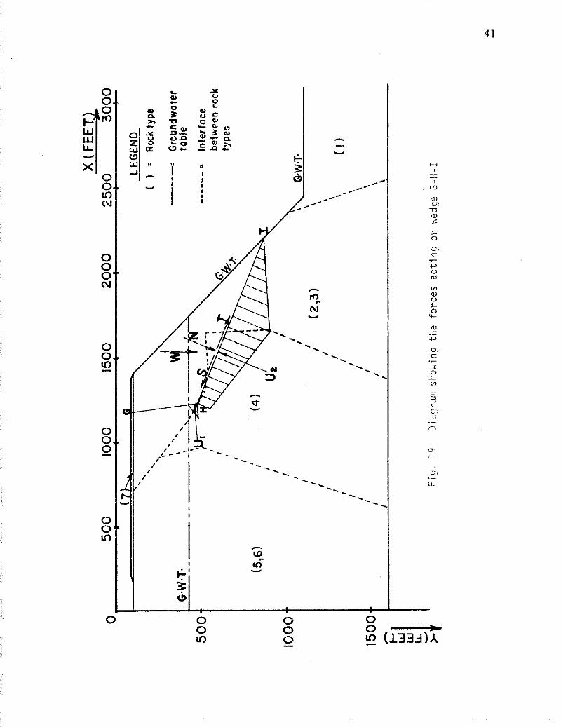
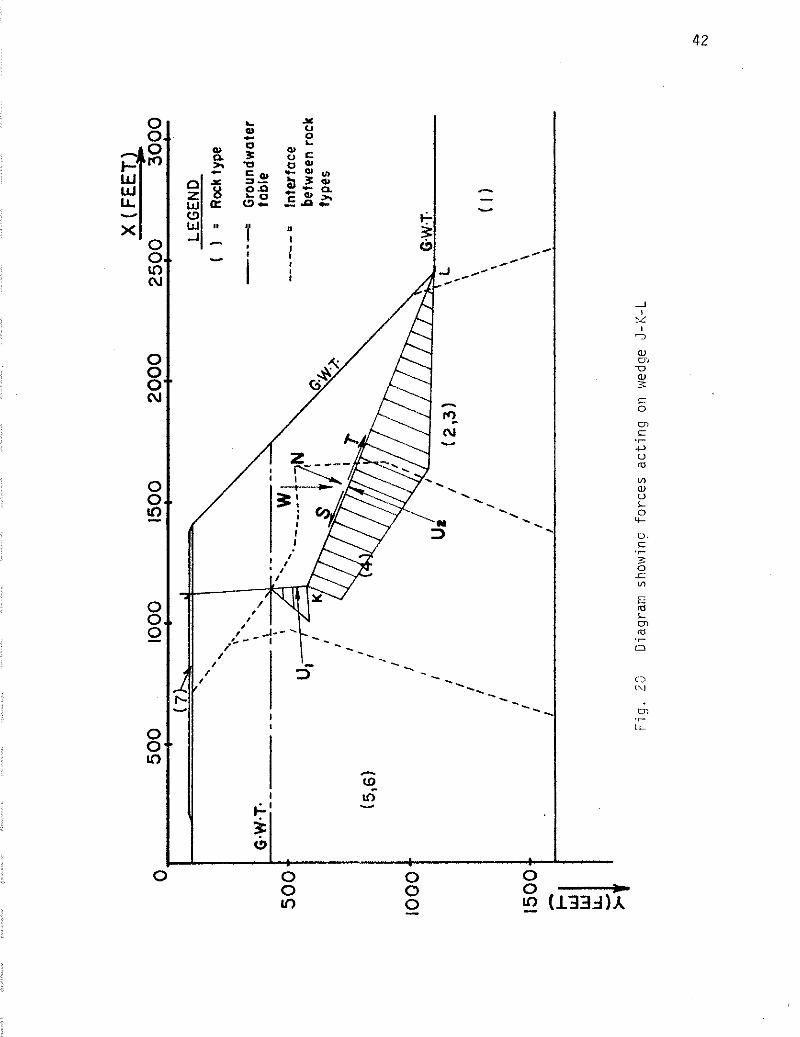
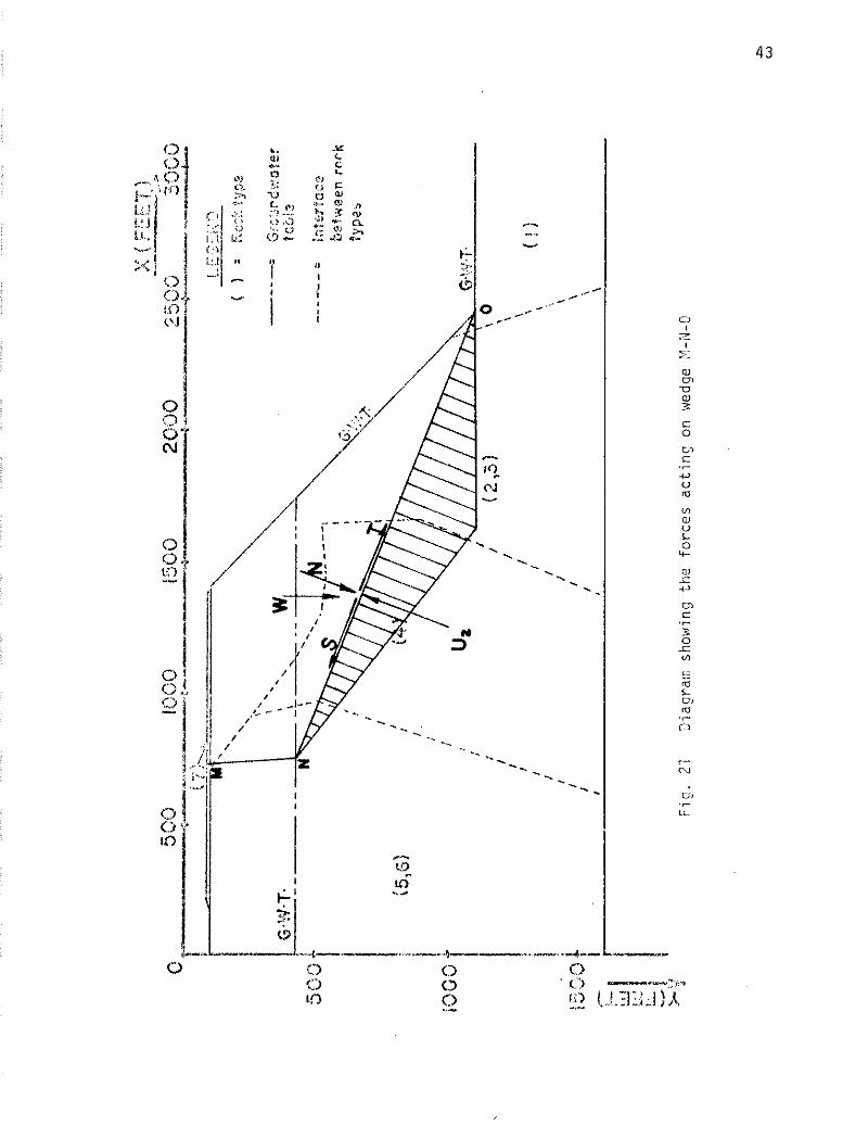
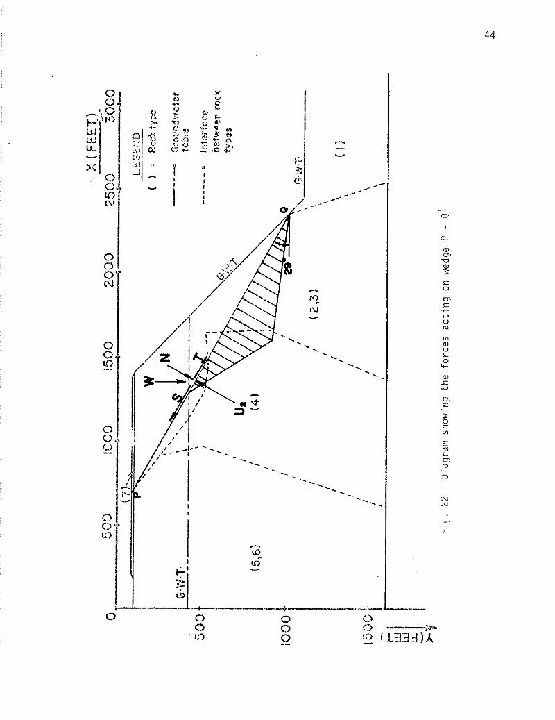
Hence, f o r a u n i t thickness, the sa fe ty f a c t o r der ived i s :
S F.S. = - D
where S = [li - U2 - U1 cos (86 - d o ) ] tan6 + c x 1
S i s the sum t o t a l o f the r e s i s t i n g shear fo rce
D i s the sum t o t a l o f the d r i v i n g fo rce
N i s the component o f weight (W) o f the rock mass a c t i n g normal t o the s l i p sur face ( = Wcosoc)
T i s t h e component o f weight o f the rock mass a c t i n g p a r a l l e l t o the s l i p sur face ( = W s i n 4 )
U2 and U1 are t h e r e s u l t a n t forces exer ted by water
C i s the cohesion
1 i s the length o f the s l i d i n g surface
o c i s the i n c l i n a t i o n o f the s l i d i n g plane
6 i s the f r i c t i o n angle (where two m a t e r i a l s are invo lved , a weighted average i s used)
F.S i s the f a c t o r o f s a f e t y
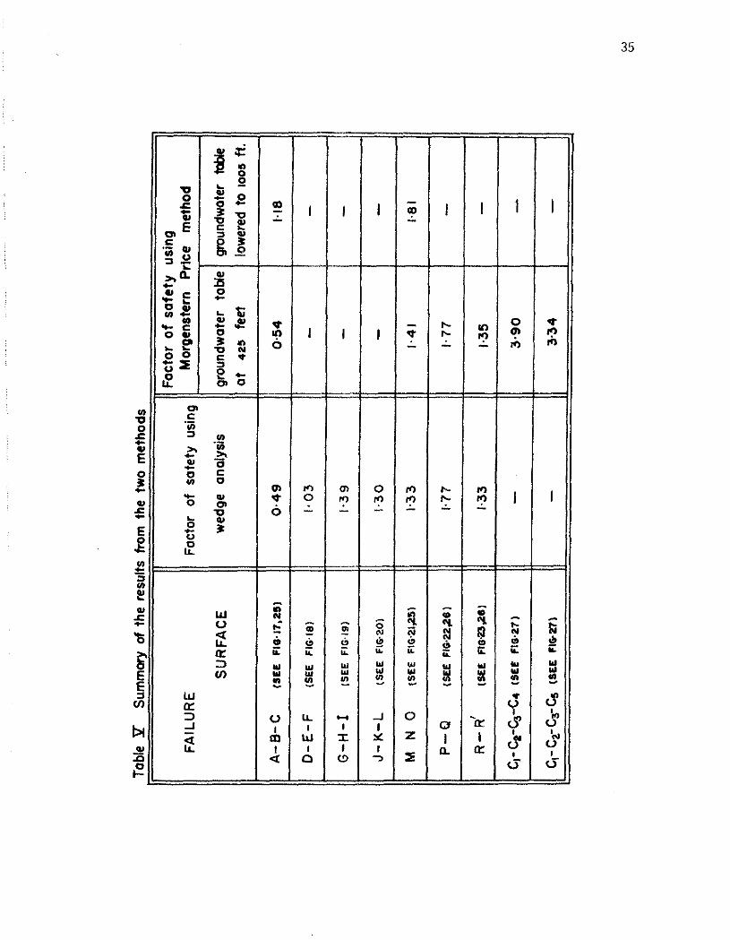
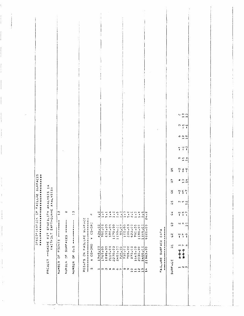
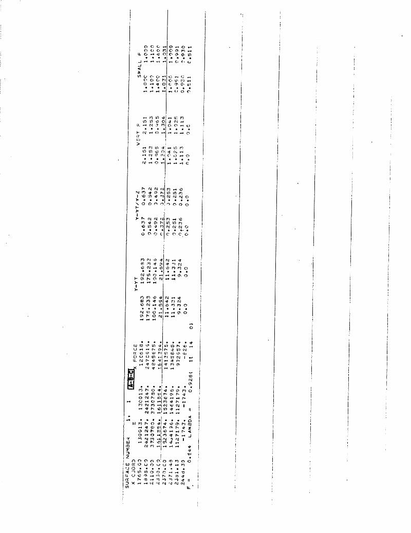
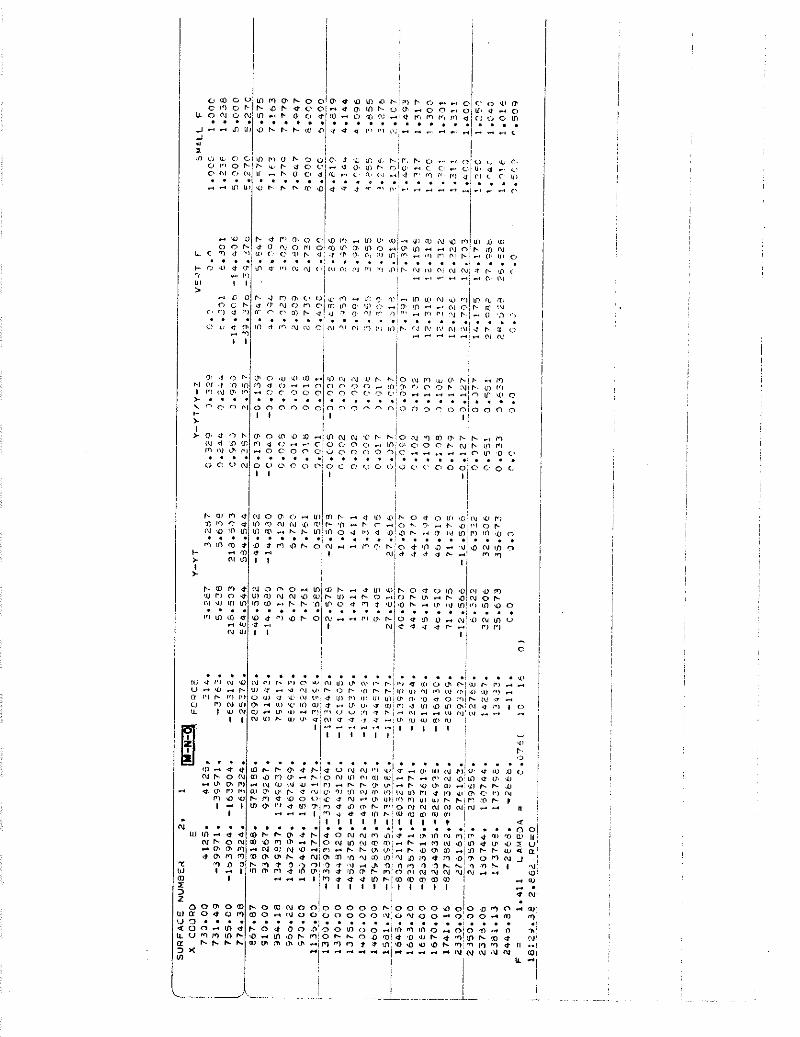
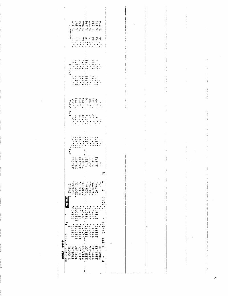
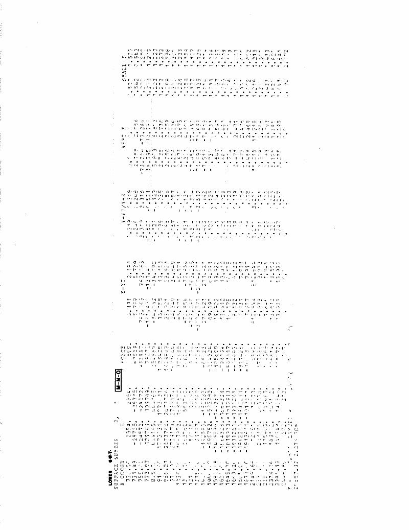
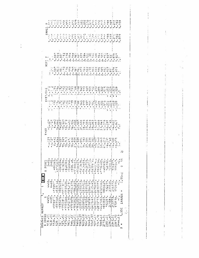
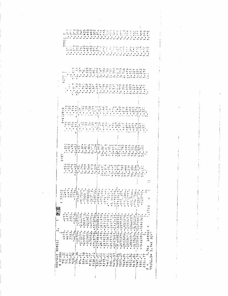
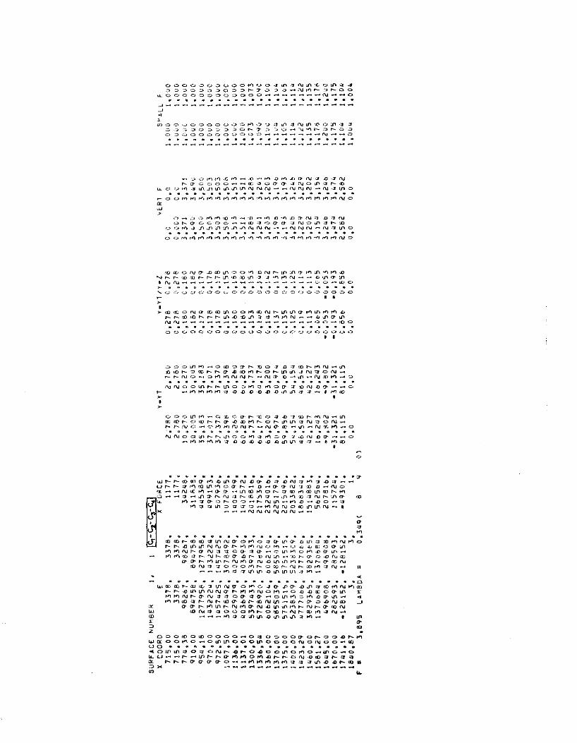
The r e s u l t s o f t h e wedge and Morgenstern-Price analyses a r e
presented i n Table I11 and I V r espec t i ve l y . Table V sumnarizes the
s a f e t y f a c t o r s der ived f rom the two methods. Ca l cu la t i ons and o t h e r
p e r t i n e n t i n fo rma t i on are g iven i n t he Appendix.
Tobl
e II
R
ock
stre
ngth
par
amet
ers
Tobl
e Dl
Res
ults
fro
m .w
edge
ana
lysi
s
6,
C gi
ven
abov
e ar
e th
e w
eigh
ted
aver
age
valu
es
U2 a
nd
U1 a
re t
he r
esu
ltan
t fo
rces
exe
rted
by
w
ater
Tabl
e P
Su
mm
ary
of t
he r
esul
ts f
rom
the
tw
o m
etho
ds
It
1
FA
ILU
RE
J- K
-L
(SE
E
FIG
20
1
SU
RF
AC
E
CI-
C2-
CsG
(S
EE
F
IG27
1 -
33
4
-
~~~t
~~ o
f u
sin
g
Fact
or o
f sa
fety
us
ing
Mor
gens
tern
P
rice
m
etho
d
+
wed
ge
onol
ysis
gr
ound
wat
er
tabl
e a
t 4
2s
fe
e9
grou
ndw
ater
W
e
low
ered
to
loor
ft.
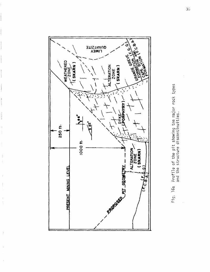
Fig
. 16
a P
rofi
le o
f th
e p
it s
how
ing
the
ma
jor
rock
typ
es
and
the
str
uc
ture
dis
co
nti
nu
itie
s.
CHAPTER VI
DISCUSSION
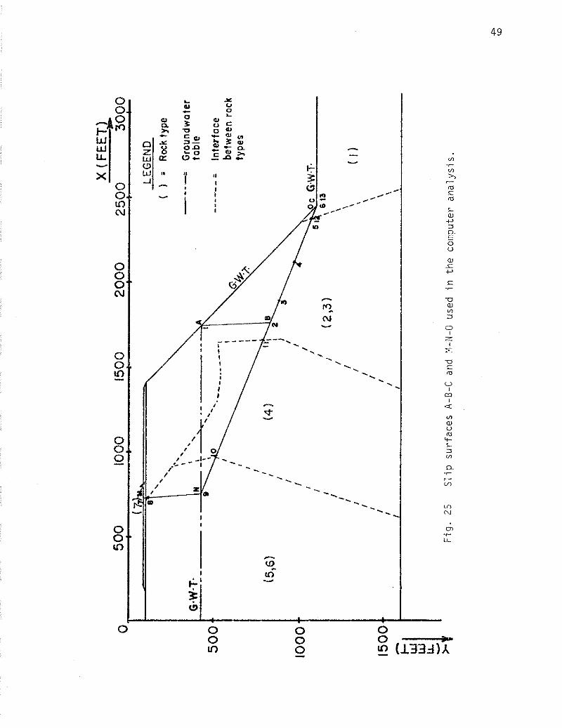
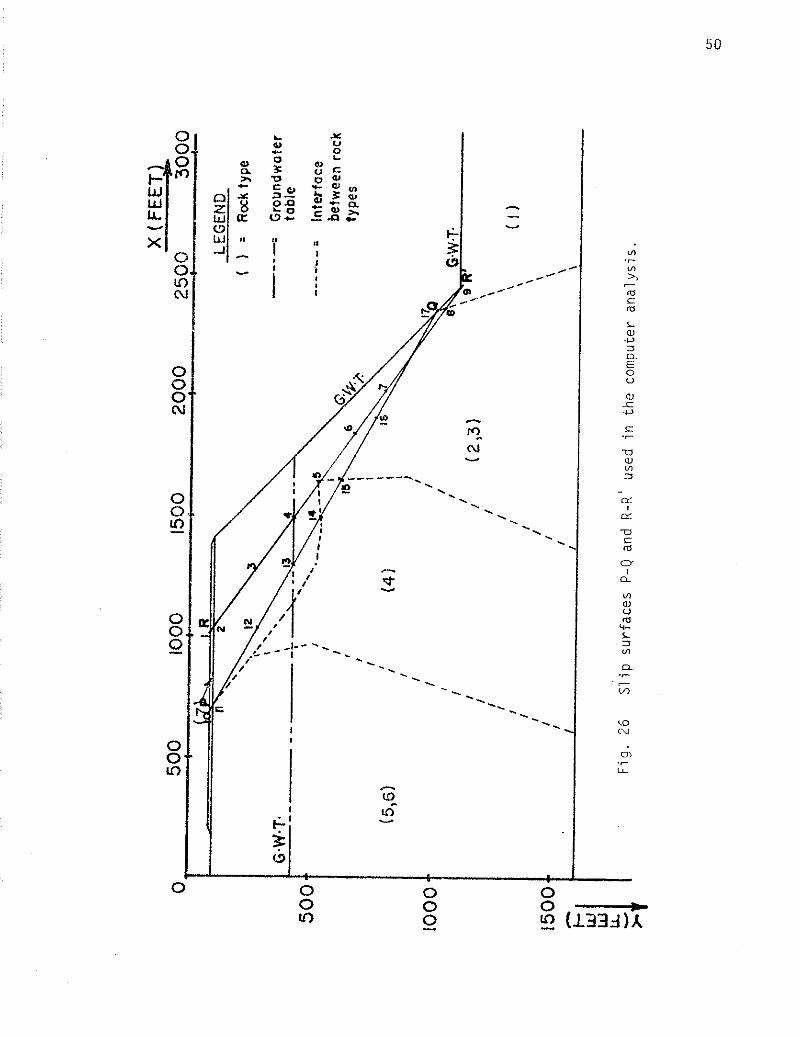
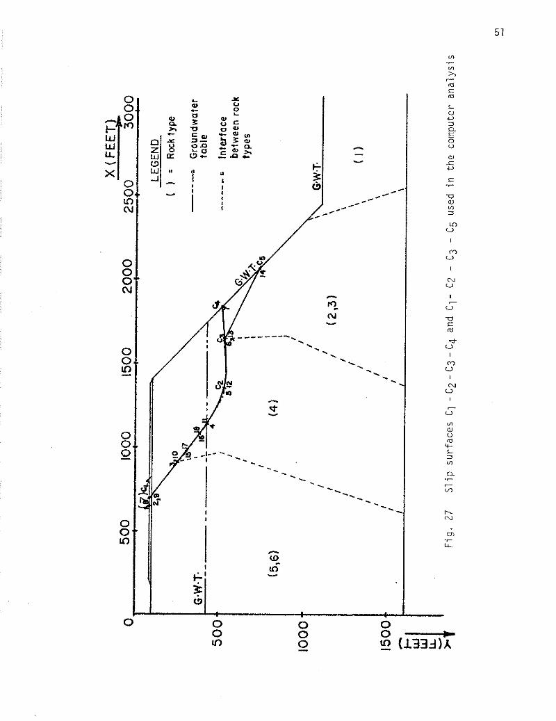
Nine possible s l i p surfaces were investigated using e i t he r
the wedge analysis or Morgenstern-Price method o r both. The factors
of safety estimated from the two methods are i n reasonable agreement.
As was expected, the r e su l t s obtained from the wedge analysis are
lower; i . e . , on the safer s ide , tlence, implications a r e , f o r rock
slopes where discont inui t ies play an important role and where the
e n t i r e rock mass moves a s one r ig id body along a planar surface a s i s
usually the case, a simple wedge analysis will suff ice provided tha t
the pore water pressures are properly accounted fo r .
CONCLUSION
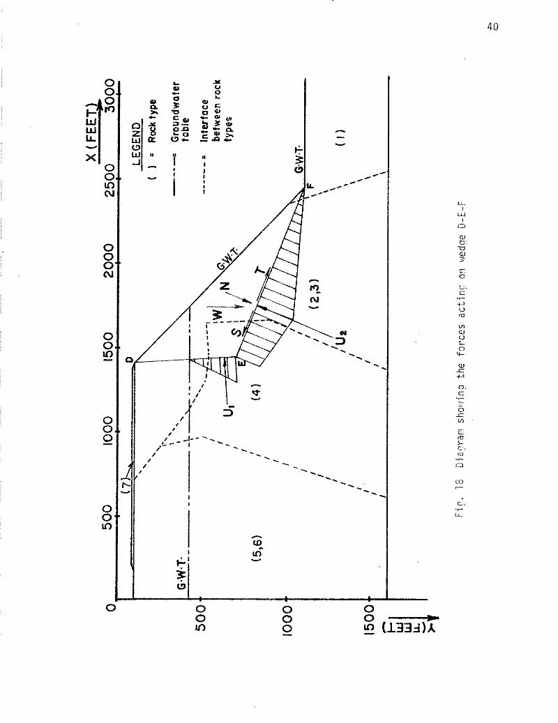
As seen in Table V , the p i t wall i s unstable unless the
water level would be su f f i c i en t ly drawn down. Otherwise, rock s l i d e
will occur possibly along a plane between the A-B-C and D-E-F surfaces.
I t i s a lso shown tha t by lowering the groundwater t ab le from i t s or iginal
level a t 425 f e e t below the surface t o 1,005 f e e t , the s t a b i l i t y condition
of the slope i s considerably improved. Hence, i t i s therefore advisable
t h a t drain holes be d r i l l ed a l l around the p i t wall a s the development
progresses t o i t s f inal depth.
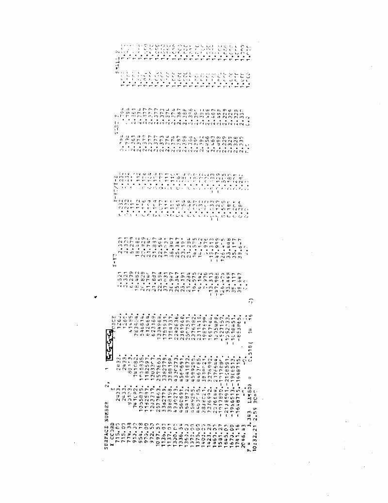
A P P E N D I X
Y-Y
I a
7.i
:i
67
.7.;
- - 2,.A
"C
x
.s
CC
>
- . .
I . # V < 0. r.1 N m , " 7' e , , . ri 1 rm o. - , r., l , ~ , -. <., .. . . a < . ' U P . . .......... l r , . , I . , . , - . ... , , - : " , < ,.:, .. cr , P, 8 c < . r . "8 . * . . ' , , . < r "4 '., :, <, ,,? .. . . . . . . . . . . . . . . . . . . . . . . . . . . .a< ... - r - r - r r r r r r r - r . r . - r - - , . , r r . r , , , -1 I: , . "> 4 , ", C.8 p, a; . <o ,. ,<, :, T~ ,- ,:. <, v , < ~ , " , r. ~ .~ < ' - a f '. P , P c.4 , + c , t r , c , . " m - . , ,' .. ,. ,.,,4:, <,
~ . . . . . . . . l . 1 . 4 . . .,..I. - r - l . . . , . r , ......>...A . . . . . . . . . . . . . . . . . . . . . . . . . . . . . - - r r . * - , ..? - - , - . * -... - .
0. (I, ir , r " 8 LT I c . i- I IU , I l o I - "1 I., (1 < I . 0 1 . ,., ,,, c. P l r- J r <.I 1 4 '.I I,, i l l r - l., ., m 3 4 , ," - . . , I , , , , , . > , . , , * a , > - , , < , - * > , , , 7 - . , ? , , . < 4 < . H . . . . . . . . . . . . . . . . . . . . . . . . . . >' . . . . . . . . . . . . . . . . . . . . . . . . . . . . . , I , , a , ,. > " " , . , , ,. r , . , , , , . , 3 < , , , . , - t . , , . . , . . . , , . . . 11 , i . , 1 .., 1.4 ',. 111 r . . . . - ... a:, > ? . ' , a , , , . . . . . . . . . . . . . . . . . . . . . . . . . . . - . : . . . . . . . . . . . . . . . . . . . . . . . . . , I O I I ,
- " , . . I . 1 U U 1 . " . 4 8 , .. 7 . , . i , i , , ~ < Y . - I - . I . .,. I , , . " r i<i . -r. .. . I . I I I (- ... ,. C , 0, C I - r r : C. r .... . , . . ' I. . . 1) . . . . ,,,? . . . . . . . .-.. ., ......... ,, ,, .'~ ,, ... . . . . . . . . . . . . . . . . . . . . . . . . . . ,.> 8 , . t.1. ., ,,> ,,, . I , r , 2 c.2 ~, 7 - 0, 0, P , ,,, , ? , . I ,, ,- ., ,., . . . . 1 , , , .. r . . . . ..
P r- I , I < I ,
I I , -
I., 0. ", L, ", ,,, I . ,o 1,s < , t- ' I , I
El-
. . . . . . -1 '1 , c. I . , >,I
'1 ii, i.. r 0 , Iy <.> c ? 3 .,, ~, ., 6 , . ., = ,< .- :x . I , . < , ,-
I., .,. I , I I :.. I I I I 6 I
a-,>,. m , . , r - ,~ - s . , * ~< m:.~ < .. ~ ,. . '. . L C . > .,:<, ....... 9 .. m . . , . . . . . . . . . . . , , . . . . . . t I-
VC . . . . . . . . . . . . . . . . . . . . . . . . . . . - .< C , I - L . m: ur . r . L< . . . . . . . l i , r . " . - - U c . :i r - " P , U ' . , " ~ < . . - r i r n , PI. . r m , r , r t c . . r . . - , i C . " ., ,ii 4;*t -rc ' -"0.0. : . . . - .......... a, , . ..wu.ti.u-.....>... 0,. .... - v - v - - F - - - - ? < " s , c , , , , \ , c , .
"I L < 4
I C * 'U ." r C O> i .Y '' "3 * U) <.,lP U;, r 0, r- I" cu r N m -7 t m m ., r N u,!n u m m p. .n.o -2 t . . n 3 rt ,: I ,.. L ., ,*LO " > P. = %>",'LC <J T- >n "4 ,,, J u, ,T r* ,v, 8kO ,G , . . . . . . . . . . . . . ., . . . . . .I. . . .. ... .. u... .......... .... 3 - l , f I, d C m m r - , U, c,.. , I -;- r .- r - N:IU ir, "'"I m ,-f in m .0 I I I I 8
I ! I
--
. -
- -
- - -
- -
......
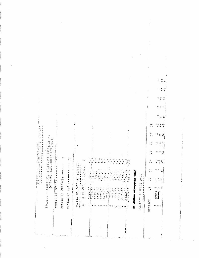
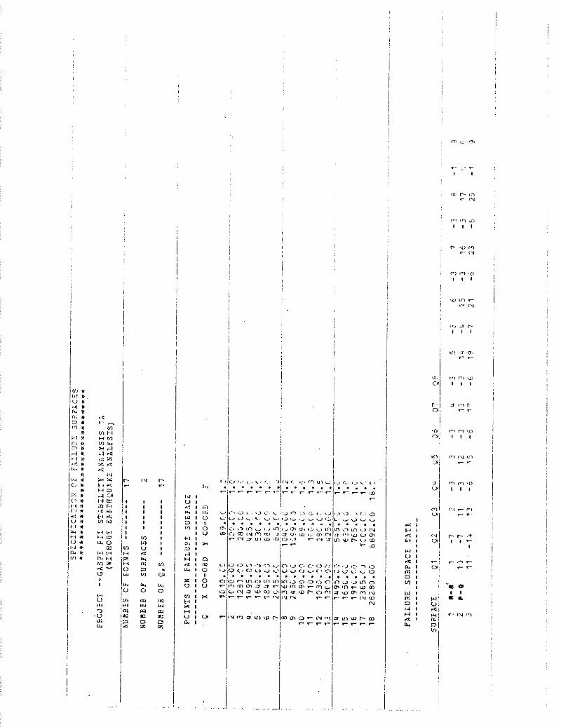
-- ....
3P
EC
IFIC
AT
ION
OF
Fb
ILU
RE
SU
RFA
CE
S
......
......
......
......
......
...
PRO
JEC
T --
GA
SP
E
PIT
ST
AB
ILIT
Y
AN
AL
YS
IS
1A
(WIT
HO
UT
EA
RTH
QU
AK
E
AN
AL
YS
IS)
- -
NU
MB
ER
OF
PO
INT
S ----
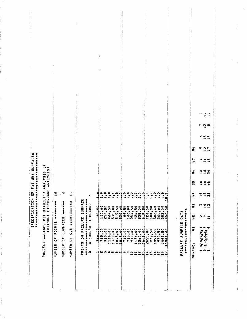
---- 18
NU
MB
ER
OF
aUR
FA
CE
5 o
----
- 2
NU
MB
ER
OF
0,s
-r--------.
11
PO
INT
S
ON
F
AIL
UR
E
SU
RFA
CE
r..--
.---
**--
---.-.--
-.*-
9 X
CO
-OR
0 Y
CO
-OR
D
F
FA
ILU
RE
S
UR
FAC
E
DA
TA
~.-
~--
-*o
--'.
-~.-
--.
-.
.~~--
.-...
--A
S
UR
FAC
E
91
0
2
Q3
QU
05
Ob
01
08
, P < I V l " , " . O . U , , , < 0, in .ii r r r, (- P P r- ,o u, n o o. ln m m ru r i ~4 r?
8.. P ,- ,., r , , ,,! ,', <" ," <.> e . , ?,> <.I n ,.> ,,> ., d 3 N "1 " ", , , . . . . . . . . . . . . . . . . . . . . . . . I I , < V ~2 C ' l <'J C 4 f,2 -4 Y N w C4 m " C 2 rv < 4 *! r.6 <" (4 N I / : / 1 > :, :, - 3 r r r- ,., 3 a P 2 7 , <, < d L O <-I 0, 0, <I\ u, r,
o n , m , r - r - r r - r r w a , o b o . i n i o u . ~ ~ ~ m P P " r l i - I ~ . ~ C I C , P I r . l ~ . i n , m i . , " i l - l ~ I C I n ,,.,<, . . . . . . . . . . . . . . . . . . . . . . . , , C " i" il t" r, I " N iU N .V <.I ' V i d " P I c , <V <, C< N <.
BIBLIOGRAPHY
Bauer, A., and Calder, P.N. (1970), "The i n f l u e n c e and eva lua t i on o f b l a s t i n g on s t a b i l i t y " , i n PROCS. OF THE FIRST INTERNATIONAL CONFERENCE ON STABILITY I N OPEN PIT MINING, pp. 83-94.
Bishop, A.W. (1955), "The use o f t he s l i p c i r c l e i n t h e s t a b i l i t y ana l ys i s o f e a r t h s lopes" , GCOTECHNIQUE, 5, 1, pp. 7-17.
Brawner, C.O. (1971), " I n t r o d u c t i o n - S t a b i l i t y i n open p i t min ing" , PROCS. OF THE FIRST INTERNATIONAL CONFERENCE ON STABILITY I N OPEN PIT MINING, Vancouver, pp. 1-3.
Cumming. L.M. (1959), " S i l u r i a n and lower devonian format ions i n t he eastern p a r t o f Gaspe Peninsula, Quebec", GEOLOGICAL SURVEY OF CANADA, Memoir 304.
Edwards, A.T., and Northwood, T.O. (19601, "Experimental s tud ies o f t h e e f f e c t s o f b l a s t i n g on s t ruc tu res " , THE ENGINEER.
Goodman, R. E., and Seed, H. B. (1966), "Earthquake-induced displacements i n sand embankments", PROC. JOURNAL SOIL MECHANICS AND FOUNDATION DIVISION, A.S.C.G., vo l . 92, no. SM2, pp. 125-146.
Goodman, R.E., Tay lo r , R.L., and Brekke, T.L. (1968), "A model f o r the mechanics o f j o i n t e d rock" , INT. SOIL MECHANICS AND FOUND. D I V . PROC., A.S.C.E., 94lSM3, pp. 637-659.
Hast, id. (19671, "The s t a t e o f s t ress i n the upper p a r t o f t he e a r t h ' s c r u s t " , ENG. GEOL., vo l . 2 , no. 1, pp. 5-17.
Hergert , G. (1973), TESTING FOR SLOPE DESIGN, w i t h c o n t r i b u t i o n s by 2 . Eisens te in , B. Ladanyi, G. Larocque, and N.R. Morgenstern.
Noek, E., and Sharp, J.C. (1970), "Improving t h e s t a b i l i t y o f rock slopes by drainage", PROCS. SYMPOSIUM ON THE THEORETICAL BACK- GROUND TO THE PLANNING OF OPEN PIT MINES WITH SPECIAL REFERENCE T O SLOPE STABILITY, Johannesburg, Rep. o f S. A f r i c a , pp. 193-198.
Hoek, E., Bray, J.W., and Boyd, J.M. (1973), "The s t a b i l i t y o f rock s lope c o n t a i n i n g a wedge r e s t i n g on two i n t e r s e c t i n g d i scon t i nu - i t i e s " , QUARTERLY JOURNAL OF ENGINEERING GEOLOGY, 6, pp. 1-58.
James, P.M. (19701, TIME EFFECTS AND PROGRESSIVE FAILURE I N CLAY SLOPES, Ph.D Thesis, U n i v e r s i t y o f London.
Janbu, N. (1954), "App l i ca t i on o f composite sl i p sur faces f o r s t a b i l i t y ana l ys i s " , PROC. EUROPEAN CONF. ON STABILITY OF EARTH SLOPES, Stockholm, 3, pp. 43-49.
Jennings, J.E. (1970), "A mathenlatic theory f o r t he c a l c u l a t i o n o f t h e s t a b i l i t y o f s lopes i n open c a s t mines", PROCS. SYMPOSIUM ON THE TliEORETICAL BACKGROUND TO THE PLANNING OF OPEN PIT MINES WITW SPECIAL REFERENCE TO SLOPE STABILITY, Johannesburg, Rep. o f S. A f r i c a , pp. 87-102.
Jones, 1.W. (1942), "Mineral depos i t i on i n Gaspe Peninsula, Quebec", ORE DEPOSITS AS RELATED TO STRUCTURAL FEATURES, Pr inceton, New Jersey, pp. 184-187.
Kenney, T.C. (1956), AN EXAIIINATION OF THE METHODS OF CALCULATING THE STABILITY OF SLOPES, M.Sc. Thesis, U n i v e r s i t y o f London.
Kennedy, B.A. (1971 ), "Methods o f mon i to r i ng open p i t s lopes", PROCS. THIRTEENTH SYMPOSIUM ON ROCK MECHANICS, Urbana, I 1 1 i n o i s , pp. 537-572.
Krahn, J. (1974), ROCK SLOPE STABILITY WITH EMPHASIS ON THE FRANK SLIDE, Ph.D Thesis, U n i v e r s i t y o f A lbe r ta .
McGerr igle, H.W. (1950), THE GEOLOGY OF EASTERN GASPE, Quebec Dept. o f Mines, Geol. Report 35.
McGerr igle, H.W. (1953), GEOLOGICAL MAP, GASPE PEIIINSULA, Quebec Dept. o f Mines, Map 1000.
McGerr igle, H.W. (1954), "An o u t l i n e o f the geology o f t h e Gaspe Peninsula", CAN. MIN. JOURNAL, v. 75, no. 8, pp. 57-63.
Morgenstern, N., and P r i ce , V.E. (1965), "The ana l ys i s o f t he s tab- i l i t y o f general s l i p sur faces" , GEOTECMNIQUE, 15, 1, pp. 79-93.
Morgenstern, N., and Pr ice, V.E. (1967), "A numerical method f o r s o l v i n g the equat ions o f s t a b i l i t y o f general s l i p sur faces" , THE COMPUTER JOURNAL, vo l . 9, no. 4, pp. 388-393.
Morgenstern, N.R. (1970), "The i n f l uence o f groundwater on s t a b i l i t y " , PROCS. OF THE FIRST INTERNATIONAL CONFERENCE ON STABILITY I N OPEN PIT MINING, pp. 65-81.
M u l l e r , L., and Hofrnann, H. (1970), "Select ion, compi la t ion and assessment o f geo log ica l data f o r t he slope problem", PROCS. SYMPOSIUM ON THE THEORETICAL BACKGROUND TO THE PLANNING OF OPEN PIT MINES WITH SPECIAL REFERENCE TO SLOPE STABILITY, Johannesburg, Rep. o f S. A f r i c a , pp. 153-170.
Or ia rd , L.L. (1971 ), " B l a s t i n g e f f e c t s and t h e i r c o n t r o l i n open-p i t min ing" , PROCS. OF THE SECOND INTERNATIONAL CONFERENCE ON STABILITY I N OPEN PIT MINING, pp. 197-222.
Patton, F.O., and Deere, O.U. (1970), " S i g n i f i c a n t geo log ic f a c t o r s i n rock s lope s t a b i l i t y " , PROCS. SYMPOSIUM ON THE THEORETICAL BACK- GROUND TO THE PLANNING OF OPEN PIT MINES WITH SPECIAL REFERENCE TO SLOPE STABILITY, Johannesburg, Rep. o f S. A f r i c a , pp. 143-151.
Seed, H.B. (1970), "Ear th s lope s t a b i l i t y du r i ng earthquakes", EARTH- QUAKE ENGINEERING, R.L. Wiegel , ed., Pren t ice-Ha l l , pp. 383-401.
Stewart, W.P. (1974), STABILITY OF THREE ROCK SLOPES, M.Sc. Thesis, U n i v e r s i t y o f A lber ta .
Terzaghi, K. (1962), " S t a b i l i t y o f steep slopes on hard unweathered rock" , GEOTECHNIQUE, v o l . 12, no. 4, pp. 251-270.
Watt, I .B. (1970), "Control f o r e a r l y warning o f p o t e n t i a l danger i n open p i t s " , PROCS. OF THE SYMPOSIUM ON THE THEORETICAL BACKGROUND TO THE PLANNING OF OPEN PIT MINES WITH SPECIAL REFERENCE TO SLOPE STABILITY, Johannesburg, Rep. o f S. A f r i ca , pp. 103-113.
Whitman, R.V. (1970), " I n f l uence o f earthquakes on s t a b i l i t y " , PROCS. OF THE FIRST INTERNATIONAL CONFERENCE ON STABILITY I N OPEN PIT MINING, pp. 95-118.