Embed Size (px)
Citation preview

Buro Happold Specialist Consulting
STRUCTURAL FIRE ENGINEERING ASSESSMENTS OF THE MOKRSKO FIRE TESTS
An Engineering Prediction
Anthony Abu, Berenice Wong, Florian Block and Ian Burgess
The University of Sheffield
and

2
Introduction
• Advanced analysis of structures in fire is only as good as the modelling.
• The programs, “the model”, used should included all relevant physical features and should be validated.
• However, “the modelling” should also be validated as it is at least as important as “the model”.
• Two full scale fire tests were conducted in 2008: the FRACOF fire test and the fire test in Mokrsko.
• A priori modelling of the of both test has been undertaken based on pre-released data and engineering assumptions.
• After the tests more detailed modelling was done.

3
The Mokrsko Fire Test – Czech Technical University of Prague
• Steel and concrete composite office building consisting of four bays with a size of 9m x 6m each.
• Tested three different floor systems:
• “Angelina” composite beams developed by Arcelor-Mittal with elongated web openings,
• Beams with corrugated webs made from thin steel plates,
• Precast hollow-core panels.
Okenní otvor
Dveře
A B C
3
2
1
9 000 9 000
+0,00
Mechanické zatížení pytli se štěrkem
Požární zatížení hranicemi dřeva
+4,00
S
Meteorog.
nad prolamovanými
nad nosníky
Duté
Okenní otvor
6 000staniceMeteorog.
stanice
s vlnitou stojinou
nosníky
předepnuté panely6 000
Sendvičové panelyBetonová stěna
Skládanýplášť
Ocelobetonová deska
Ocelobetonová deska
Sádrovétvárnice

4
Steel Frame
4

5
Beams• Angelina™ Beams are an Arcelor-Mittal product based on a sine wave cut
from an IPE270 with a total new depth of 395mm.
• The beams with the corrugated webs were 500mm with a web thickness of only 4.5mm.

6
Connection Details
All beam connections connected only the top flange and a small part of the web of each beam. The bases of the columns were constructed as pinned.

7
Composite Slab
120mm composite slab CF60 metal decking using a smooth mesh (196mm2/m) and 10mm bars in each rib.

8
View from inside
8

9
View from above
9

10
Cladding
10

11
Mechanical Loading
11
Imposed load was 3.0kN/m2 and the self-weight was 2.6kN/m2.

12
Fire Load
12
A B C
3
1
9 000 9 000
+0,00
POŽÁRNÍ ZATÍŽENÍ
+4,00
S
6 000
6 000
2
POŽÁRNÍ ZATÍŽENÍ
Timber cribs with a density of
35.5 kg/m2 generated a total fire
load of about 620MJ/m2

13
Timber cribs
13

14
Ventilation
The two openings were 2.54 m height and 4.00 m wide eachThis resulted in a Opening Coefficient of O = 0.064 m1/2.
14

15
Instrumentation Frame
15

16

17
Thermocouples
17

18

19
20

21
Test predictions – A priori• Only the 3 bays with the composite slab were modelled.
• The Angelina beams and the corrugated-web beams were represented using an effective web thickness approach.
• The beam connections were modelled as rigid.

22
Design FiresAs with a normal SFE project a number of parameters were varied in order to test the robustness of the solution. The fire was altered to produce a short-hot fire (1) and a cooler-longer fire (3). The real fire (4) burned cooler than predicted (2).
0
200
400
600
800
1000
1200
0 30 60 90 120 150 180Time [minutes]
Gas
Tem
pera
ture
[°C
]1
2
3
4

23
Results of a priori modelling
-1000
-800
-600
-400
-200
0
0 15 30 45 60 75Time [minutes]
Ver
tical
def
lect
ion
[mm
]
1 2
3
4
• No indication of collapse but the vertical deflections are larger than span/15, which would normally result in an increase of reinforcement to limit the vertical deflections.
• All beams framing into columns would be protected in a robust design for fire.
• Much earlier increase in deflections than the experimental results as the parametric fire curves represent post-flashover fires, and should be moved by about 15min to give a realistic representation of the fire.

24
Test day – 18/09/2008

25

26

27

28

29
Test Video 1
30
Test Video 2

31
1st Structural Collapse of a Large Scale Fire Test

32

33

34
35
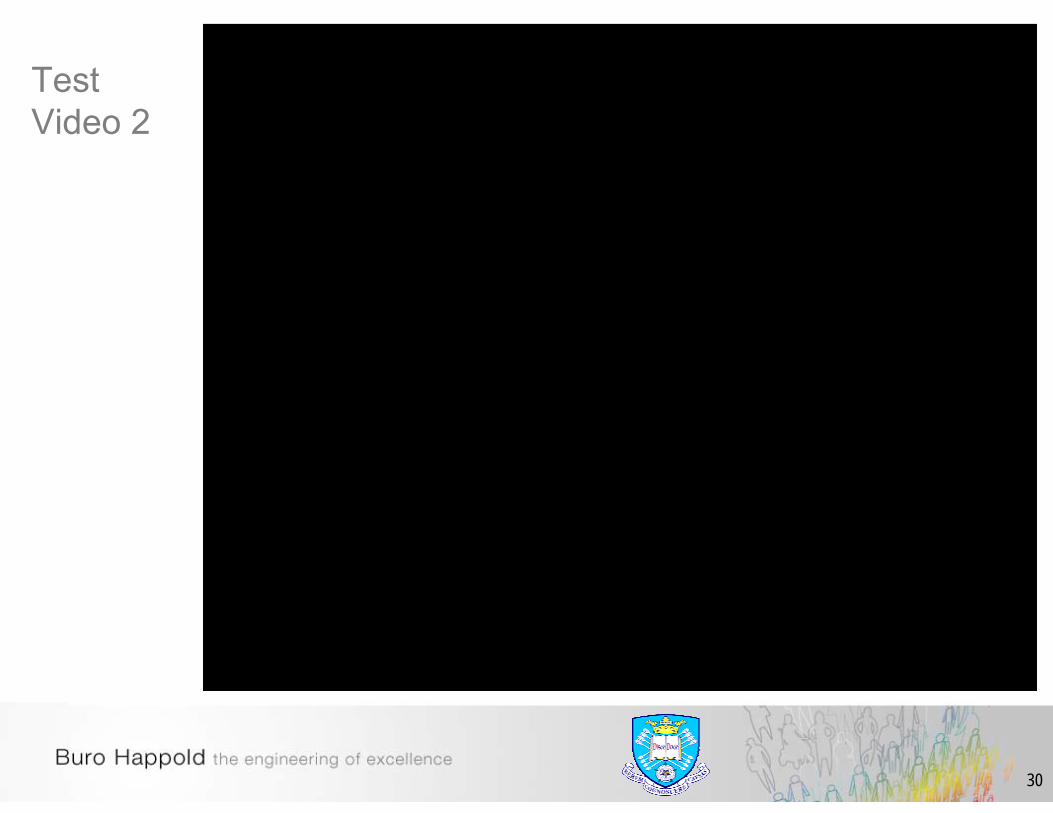
Crack Pattern of Slab
35

36

37
Composite Slab Corner

38
Compartment Temperatures - Back
38
0
200
400
600
800
1000
0 15 30 45 60 75
TG01
TG07
Teplota plynu [°C]
Čas [min]
Průměr změřenýchteplot plynu
TG07
TG01
Okenní otvory
Termočlánek
Termočlánek

39
Compartment Temperatures - Front
39
TermočlánekTeplota plynu [°C]
Čas [min]0
200
400
600
800
1000
15 300 45 60 75
TG12
Průměr změřenýchteplot plynu
TG11 TG12Okenní otvory
TG11
Termočlánek

40
Compartment Temperatures - Left
40
Teplota, °C
TG09
TG10
TG07
TG08
0
100
200
300
400
500
600
700
800
900
1000
1100
0 15 30 45 60 75 Čas, min
TG07
TG10
TG08TG09
Průměr zTG07,TG08,TG09,TG10

41
Compartment Temperatures - Right
41
0
100
200
300
400
500
600
700
800
900
1000
1100
0 15 30 45 60 75 Čas, min
Teplota, °C
TG01
TG04TG05
TG06Průměr z
TG01,TG04,TG05,TG06
TG01
TG04
TG05
TG06

42
Steel Temperatures – Angelina Beams
42
0
AS6
15 30 45
100200300400500600700800900
1000
AS2
AS5
AS4
Teplota [°C]
Čas [min]0
AS2
AS4AS5AS6

43
Vertical Deflections
43
15 30 45
-200
-400
-600
-800
-1000
0 0
Deformace [mm]
V3
V1
V7
V5
Čas [min]
-100
-300
-500
-700
-900 V1
V3
V5
V7

44
Temperatures of Corrugated Web Beams
44
Teplota [°C]
Čas [min]
TC21
0100200300400500600700800900
1000
0 15 30 45 60 75
TC22
TC23TC79
TC80
TC22
TC79
TC21
TC23
TC80

45
Deformed Shape of Corrugated Web Beams
46
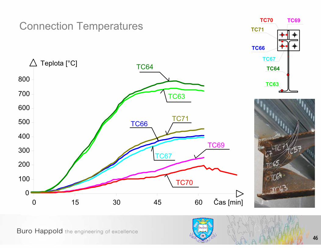
Connection Temperatures
46
0
100
200
300
400
500
600
700
800
0 15 30 45 60
Teplota [°C]
TC69
TC71TC66
TC67
TC64
TC63
TC70
Čas [min]
TC64
TC63
TC71
TC66
TC67
TC69TC70

47
Block shear failure of beam web

48
Concrete Spalling

49
Concrete Spalling

50
Concrete Spalling

51
Laser mapping of spalling on back wall

52
0100200300400500600700800900
1000
0 15 30 45 60 75Time [min]
Tem
pera
ture
[°C
]
TC32TC33TC34TC35TC36TC37TC38
Concrete Slab Temperatures

53
Concrete Slab Temperatures
0
50
100
150
200
250
0 15 30 45 60 75Time [min]
Tem
pera
ture
[°C
]
TC33TC34TC35TC37TC38

54
Vulcan – Modelling directly after the Test – Deflected Shape

55
Vertical deflection comparison
-1000
-800
-600
-400
-200
0
0 15 30 45 60 75Time [minutes]
Ver
tical
def
lect
ion
[mm
]
V3
V1
V7
V1
V3
V7• The deflection curves
show that when the real temperature data is used the vertical deflections are represented accurately up to about 44 minutes.
• The difference between prediction and reality for the beams with corrugated webs (V7) can be explained by the observed shear buckling of the thin webs.

56
Horizontal movement of the mid column
-35
-30
-25
-20
-15
-10
-5
0
5
0 15 30 45 60 75Time [minutes]
Hor
izon
tal d
efle
ctio
n [m
m]
H1
+
H1
• Due to the very flexible beam connections, therefore the connections were modelled as pinned.
• In these cases the Vulcanmodels stops around 43 minutes.
• The horizontal displacement at the top of the edge column connected to an unprotected Angelina beam.

57
New modellingExact cause of failure of the structure - unknown
Possibly due to:• Failure of middle column• Compression failure of slab• Failure of connections• Unzipping of slab from edge beams• Buckling of back edge beam• Reversal of crack in Angelina bay
Determine:• Approximate magnitudes of tensile forces in concrete• Approximate magnitudes of compressive stresses in concrete• Connector force distribution along the beam edge• Axial forces in the back edge beam• Effects of spalling on failure• Failure initiation and eventual collapse of the structure
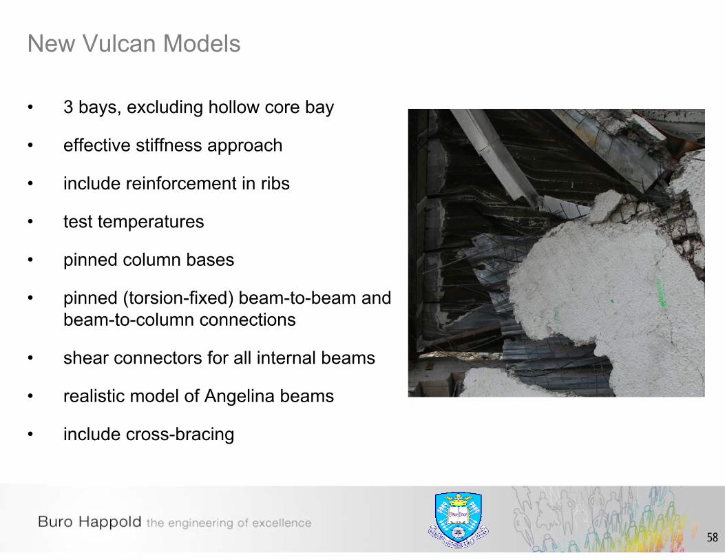
58
• 3 bays, excluding hollow core bay
• effective stiffness approach
• include reinforcement in ribs
• test temperatures
• pinned column bases
• pinned (torsion-fixed) beam-to-beam and beam-to-column connections
• shear connectors for all internal beams
• realistic model of Angelina beams
• include cross-bracing
New Vulcan Models

59
Angelina Beam - Models
Comparison of models to find equivalent model for use in Vulcan
Initial analyses (comparisons) with bare steel beams – ABAQUS
Angelina Beam
Effective web thickness
Vierendeel girder
Truss
Composite beam comparisons with Vulcan
Effective web thickness
Vierendeel girder

60
Modelling of Angelina beams
Beam B2
Beam B
Beam A

61
Abacus deflected shape – Beam A

62
Abacus deflected shape – Beam B1
63
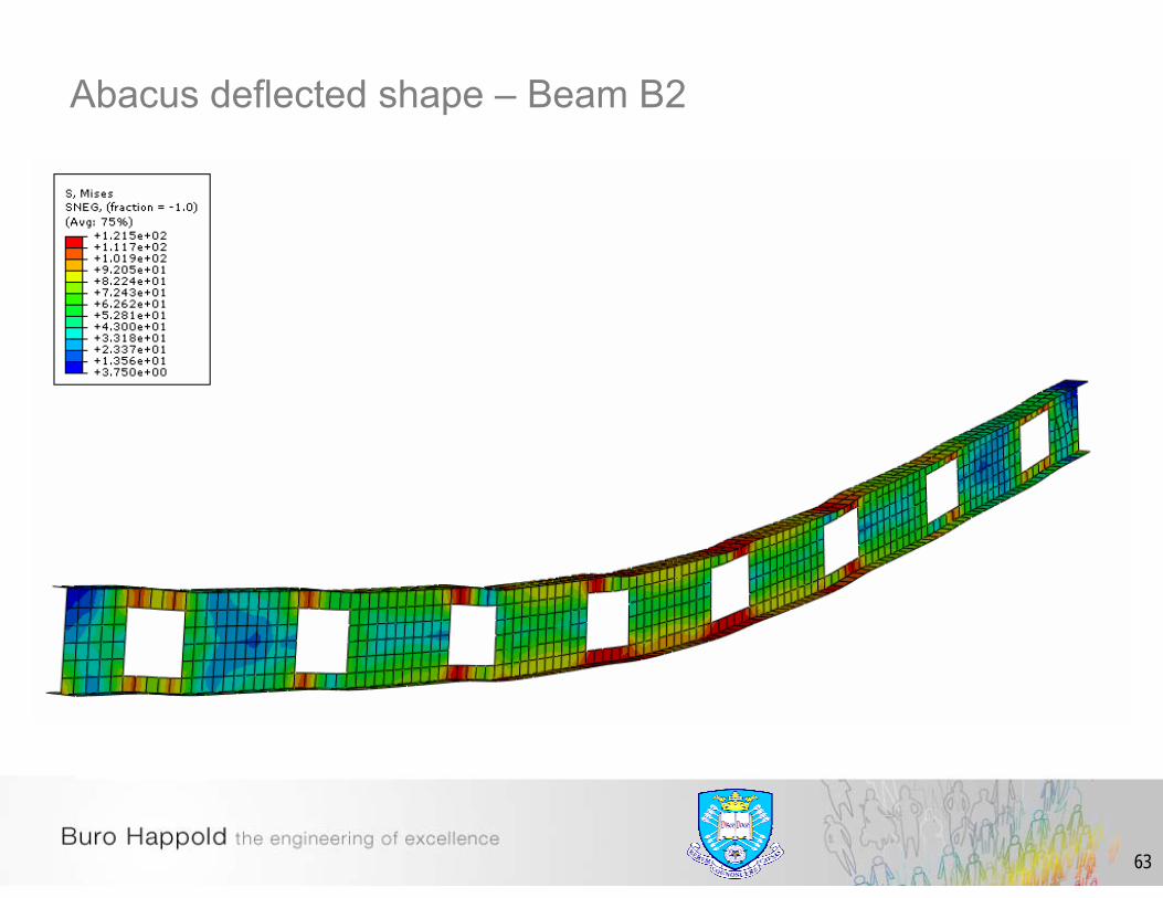
Abacus deflected shape – Beam B2

64
Abacus deflected shape – Effective web thickness

65
Abacus – Deflection comparison – Ambient Temperature
Angelina beam (ambient)
0
20
40
60
80
100
120
140
160
0 50 100 150 200 250
mid-span displacement (mm)
App
lied
load
ing
(kN
)
Beam ABeam BBeam B2Solid beam (eff. thickness)Truss

66
Abacus – Deflection comparison – Elevated Temperature
Steel Temp vs Displacement(applied load =70kN)
-700
-600
-500
-400
-300
-200
-100
00 100 200 300 400 500 600 700
Steel Temp
mid
-spa
n di
spla
cem
ent (
mm
)
Beam ABeam BBeam B2Solid beam (eff. thickness)Truss

67
Angelina Beam - VulcanAmbient15kN/m2 applied load
Elevated7.5kN/m2 applied loadStandard FireUniform heating – beamNon-uniform heating - slab
Section A Section BA
A
B
B
68
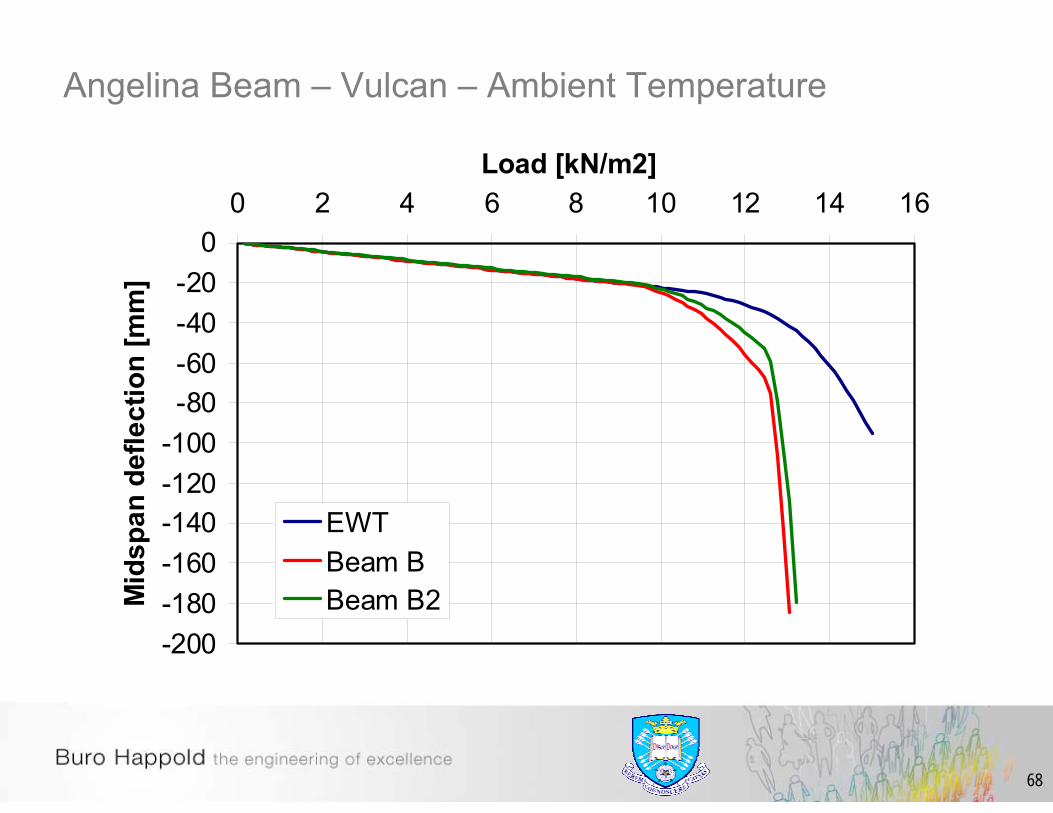
Angelina Beam – Vulcan – Ambient Temperature
-200-180-160-140-120-100-80-60-40-20
00 2 4 6 8 10 12 14 16
Load [kN/m2]M
idsp
an d
efle
ctio
n [m
m]
EWTBeam BBeam B2

69
Angelina Beam – Vulcan – Elevated Temperature
-2000-1800-1600-1400-1200-1000-800-600-400-200
00 100 200 300 400 500 600 700 800
Temperature [°C]D
efle
ctio
n [m
m]
Beam BBeam B2EWT

70
• Beam B2 used for initial analysis – large model – long runtime
• Effective web thickness approach used for most analyses
• Protection material Promatech – H (15mm thick board–870kg/m3, 920J/kgK, 0.21W/mK)
• Reinforcement - S500 (mesh 5mm 100/100 + 10mm bar in ribs)
• Concrete, fcu = 34MPa
• Steel fy = S235 (corrugated beams = S320)
• 19mm diameter shear connectors (3 per 1m)
• Beam-to-beam, and beam-to-column connections = pinned
• Effective stiffness approach for the slab
• Bracings
• Test temperatures – gas temperature
Main Analysis - Assumptions

71
New Vulcan Models

72
New Vulcan Models

73
• Realistic fires should be considered including the cooling phase.
• Integrity failure of the floor slab should be controlled by either deflection/curvature limits or finite cracking modeling.
• Reinforcement mesh in the slab must be sufficiently lapped to form a full tension lap.
• All edge beams should be composite and the slab should be tied to the beams.
• All columns should be tied in by protected beams.
• Connections should be designed to be ductile.
Important points
0
200
400
600
800
1000
1200
0 15 30 45 60 75 90 105 120
Time (minutes)
Tem
pera
ture
(°C
)

74
Conclusion
• Conservative overall predictions of the response of composite structures to fire using sophisticated FE programs could be made.
• It was not possible to predict the failure mode or time prior to the tests but Vulcan could model the overall behaviour of both fire tests accurately when the correct input data was used.
• The tests showed that failure of structures is often caused by details! Therefore, robust construction details should be used until computer modelling can include these phenomena.
• Everyone who predicts the behaviour of structures in fire using FEA should validate their “modelling” against simple and well documented experimental data as well as full scale tests.
• Further modelling required to find cause of failure.


![Overview - University of Sheffieldfire-research.group.shef.ac.uk/steelinfire/downloads/CTD_09.pdf · Microsoft PowerPoint - Ppt0000013 [Read-Only] Author: Ian Burgess Created Date:](https://img.pdfslide.net/doc/110x75/5f5ec56da79c2c0d89689863/overview-university-of-sheffieldfire-microsoft-powerpoint-ppt0000013-read-only.jpg)