Embed Size (px)
Citation preview
E
The University of Western Australia
Design and Construction Standards HYDRAULIC SERVICES
Hydraulic Services E
UWA Design and Construction Standards Page 1 of 32
DOCUMENT CONTROL
REVISION LOG
Current Issue
UWA Design and Construction Standards: Hydraulic Services - E, Version 1.0 (September 2016)
Previous issues
Version Author(s) Description Date completed 1.0 Campus
Management UWA Design and Construction Standards: Hydraulic Services - E
REVISION MANAGEMENT
It is envisaged that revisions to this document will be undertaken at intervals of not more than two (2) years.
ENDORSEMENT BODY
To be determined.
OWNER
Director, Campus Management
AUTHOR(S)
The Standards have been developed by Campus Management with the assistance of UWA staff, external
consultants, contractors and colleagues from other education institutions.
CONTACT PERSON
Associate Director Capital Works, Campus Management
COPYRIGHT
This document is the property of The University of Western Australia and may not be copied as a whole or in part
without the approval in writing of the Associate Director Capital Works, Campus Management.
Hydraulic Services E
UWA Design and Construction Standards Page 2 of 32
Table of Contents
1 Introduction ......................................................................................................................................... 4 1.1 Purpose ............................................................................................................................................ 4 1.2 Services ........................................................................................................................................... 4 1.3 Related Documents ......................................................................................................................... 5
1.3.1 University Documents .............................................................................................................. 5 1.3.2 Relevant Legislation ............................................................................................................ 5 1.3.3 Manufacturer Specifications and Data Sheets .................................................................... 5 1.3.4 Project Specific Documentation .......................................................................................... 5
1.4 Discrepancies .................................................................................................................................. 6 1.5 Departures ....................................................................................................................................... 6 1.6 Professional Services ...................................................................................................................... 6 1.7 Structure of Document ..................................................................................................................... 6 1.8 Definitions ........................................................................................................................................ 7
2 General Requirements ........................................................................................................................ 8 2.1 Regulatory Requirements ................................................................................................................ 8 2.2 Design Considerations ..................................................................................................................... 8 2.3 Co-ordation ofServices .................................................................................................................... 8 2.4 Mains Water ..................................................................................................................................... 9
2.4.1 Hot Water ............................................................................................................................ 9 2.4.2 Cold Water ........................................................................................................................ 10 2.4.3 De-Ionised Water / Reverse Osmosis .............................................................................. 11
2.5 Natural Gas .................................................................................................................................... 12 2.6 Sewer ............................................................................................................................................. 12
2.6.1 External ............................................................................................................................. 12 2.6.2 Internal Wet Areas ............................................................................................................ 13 2.6.3 Plant Rooms ...................................................................................................................... 13 2.6.4 Mechanical Waste ............................................................................................................. 14 2.6.5 Industrial Waste ................................................................................................................ 14
2.7 Stormwater ..................................................................................................................................... 14 2.7.1 Stormwater Drainage ........................................................................................................ 15 2.7.2 Gutters and Downpipes .................................................................................................... 15
2.8 Waste water ................................................................................................................................... 15 2.9 Fire Service .................................................................................................................................... 15
2.9.1 Fire Hydrants ..................................................................................................................... 15 2.9.2 Fire Hose Reels ................................................................................................................ 16 2.9.3 Pipework and Valves ........................................................................................................ 16
2.10 Plumbing Fixtures / Tap Ware ....................................................................................................... 17 2.11 Identification of Services ................................................................................................................ 18
2.11.1 Pipework ........................................................................................................................... 18 2.11.2 Valves ............................................................................................................................... 19
2.12 Building Works ............................................................................................................................... 19 2.12.1 Access ............................................................................................................................... 19 2.12.2 Fire Stopping of Service Penetrations .............................................................................. 19 2.12.3 Acoustic Attenuation ......................................................................................................... 20
2.13 Metering ......................................................................................................................................... 20 2.14 External Site Requirements ........................................................................................................... 21
2.14.1 Approvals .......................................................................................................................... 21
Hydraulic Services E
UWA Design and Construction Standards Page 3 of 32
2.14.2 In Ground Services ........................................................................................................... 21 2.14.3 Covers and Grates ............................................................................................................ 22 2.14.4 Excavation and Backfill ..................................................................................................... 22 2.14.5 Redundant Services .......................................................................................................... 22
2.15 Samples ......................................................................................................................................... 23 2.16 Testing and Certification ................................................................................................................ 23
4 Checklist for Project Team ............................................................................................................... 25 5 Specifications .................................................................................................................................... 27
5.1 Identification Colours ..................................................................................................................... 27 5.2 Sanitary Plumbing Fixtures / TapWare .......................................................................................... 27
Abbreviations ................................................................................................................................................ 31 References ..................................................................................................................................................... 32
Hydraulic Services E
UWA Design and Construction Standards Page 4 of 32
1 Introduction
PURPOSE 1.1
The UWA Design and Construction Standards (the Standards) outline UWA’s expectations for its built forms in
order to achieve consistency in the quality of the design and construction of those built forms. They are aligned
with the UWA’s Campus Plan 2010 planning principles and UWA’s requisites for aesthetic appeal, maintainability
and environmental sustainability, while ensuring that there is sufficient scope for innovation and technological
advancements to be explored within each project.
The Standards are intended for use by any parties who may be involved in the planning, design and construction
of UWA facilities. This includes external consultants and contractors, UWA planners, designers and project
managers as well as faculty and office staff who may be involved in the planning, design, maintenance or
refurbishment of facilities. These Standards also provide facility managers, maintenance contractors and other
service providers with an understanding of UWA services in order to assist in the maintenance and operation of
facilities.
SERVICES 1.2
The UWA Design and Construction Standards for Hydraulic Services (this document) are a part of UWA
Design and Construction Standards set of documents (the Standards). The Standards are divided into the
following service documents for ease of use, but must be considered in its entirety, regardless of specific
discipline or responsibilities:
A Building and Architecture
B Mechanical Services
C Electrical Services
D Communication Services
E Hydraulic Services (this document)
F Security Services
G Fire Services and Fire Safety Engineering
H Structural Works
I Civil Works
J Irrigation Services
K Sustainability
L Vertical Transport
Hydraulic Services E
UWA Design and Construction Standards Page 5 of 32
RELATED DOCUMENTS 1.3
1.3.1 University Documents
The Standards are to be read in conjunction with the following relevant University documents:
• UWA General Preliminaries Document
• UWA Specification for As-Constructed Documentation
• Relevant UWA planning and policy documents such as the UWA Campus Plan, Commercial Masterplan,
Landscape Vision and Integrated Infrastructure Strategy, University Policy on Alterations to University
Buildings, etc.
• Relevant UWA operational and maintenance documents such as preferred vendors lists, room data sheets,
operational and maintenance manuals, etc.
• Other documents as referenced within the UWA Design and Construction Standards.
1.3.2 Relevant Legislation
The planning, design and construction of each UWA facility must fully comply with current relevant legislation,
including but not limited to:
• Relevant Australian or Australian / New Zealand Standards (AS/NZS),
• National Construction Code (NCC),
• Occupational Safety and Health (OSH) legislation,
• Disability Discrimination Act (DDA),
• Accessibility Aspiration Design Factors, and
• Local council and authority requirements.
1.3.3 Manufacturer Specifications and Data Sheets
All installation must be carried out in accordance with manufacturer specifications and data sheets to ensure
product performance over its intended life and so as not to invalidate any warranties.
1.3.4 Project Specific Documentation
Requirements specific to a particular project, campus or other variable, will be covered by project specific
documentation, such as client briefs, specifications and drawings. These Standards will supplement any such
project specific documentation.
The Standards do not take precedence over any contract document, although they will typically be cross-
referenced in such documentation.
Extracts from the Standards may be incorporated in specifications, however it must remain the consultant’s and
contractor’s responsibility to fully investigate the needs of the University and produce designs and documents

Hydraulic Services E
UWA Design and Construction Standards Page 6 of 32
that are entirely ‘fit for purpose’ and which meet the ‘intent’ of the project brief.
DISCREPANCIES 1.4
The Standards outline the University’s generic requirements above and beyond the above mentioned legislation.
Where the Standards outline a higher standard than within the relevant legislation, the Standards will take
precedence.
If any discrepancies are found between any relevant legislation, the Standards and project specific
documentation, these discrepancies should be highlighted in writing to the Associate Director Capital Works,
Campus Management.
DEPARTURES 1.5
The intent of the Standards is to achieve consistency in the quality of the design and construction of the
University’s built forms. However, consultants and contractors are expected to propose ‘best practice / state of
the art’ construction techniques, and introduce technological changes that support pragmatic, innovative design.
In recognition of this, any departures from relevant legislation, or the Standards, if allowed, must be confirmed in
writing by the Associate Director Capital Works, Campus Management.
Any departures made without such written confirmation shall be rectified at no cost to UWA.
PROFESSIONAL SERVICES 1.6
For all works, it is expected that suitably qualified and experienced professionals are engaged to interpret and
apply these Standards to UWA projects. Works cannot be carried out by unqualified and unlicensed consultants
or contractors.
STRUCTURE OF DOCUMENT 1.7
This document is structured into 4 parts:
Part 1 Introduction (this Section)
Part 2 General Requirements – outlines the general requirements or design philosophies adopted at
UWA
Part 3 Checklist for project team (if applicable) – checklist of items for consideration at various stages of
a project
Part 4 Specifications (if applicable) – materials specifications and/or preferred lists for materials,
processes or equipment used by UWA.
Hydraulic Services E
UWA Design and Construction Standards Page 7 of 32
DEFINITIONS 1.8
For the purpose of this document, the following definitions apply:
Can: Implies a capability of possibility and refers to the ability of the user of the document, or to a
possibility that is available or might occur.
May: Indicates the existence of an option.
Shall: Indicates that a statement is mandatory.
Should: Indicates a recommendation.
Hydraulic Services E
UWA Design and Construction Standards Page 8 of 32
2 General Requirements
REGULATORY REQUIREMENTS 2.1
All hydraulics work including but not limited to sanitary plumbing, industrial waste systems, property sewers,
water supply and fire services and stormwater drainage shall be carried out in accordance with the Water
Corporation Plumbing By-laws, National Construction Code (NCC), Department of Fire and Emergency Services
(DFES) requirements and local authority by-laws.
All natural gas services work shall be carried out by an authorised installer possessing a current certificate of
competency issued by Energy Safety and suitably endorsed in the relevant classes of work.
All plumbing work, fire services and rainwater pipes and stormwater drainage shall be carried out by registered
plumber with a full and current license with the Water Corporation.
Applications and permits must be submitted to the relevant authorities before commencement of work.
Trade waste application and plans must be submitted to the Water Corporation (including Radiological Council
where applicable). Approvals must be received prior to commencement of any works.
DESIGN CONSIDERATIONS 2.2
The following shall be given special design considerations:
• Location of machinery and plant – not permitted on roofs without UWA approval
• Access to plant, plant rooms, valves, cleanouts and equipment – confined spaces shall be avoided at all
times
• Water quality
• Water and energy efficiency
• Fire hydrant / fire hose reel coverage
• Alternative firefighting solutions
• Stormwater treatment
• Industrial waste pre-treatment
• Design for industrial waste – consult with relevant UWA Faculty or School for chemical discharge data
• Health and safety of building users and operators
• Environmental sustainability
• Whole of life consideration
• Material selection – availability, recyclability, maintainability, disposal.
CO-ORDATION OFSERVICES 2.3
Ensure co-ordination of the design and installation of hydraulic services with other services to ensure adequate
provisions are allowed for and to minimise conflict with other services (e.g., location of access hatches, ceiling

Hydraulic Services E
UWA Design and Construction Standards Page 9 of 32
space allowances, etc.). This includes:
• Electrical power supply to pump switchboards, hot water units, boiling water units, ice machines,
dishwashers, chilled water units, autoclaves, process water pumps, de-ionised water pumps and Fire
Drencher Flow switch.
• Connection of hydraulic services points (meters, solenoids, etc.) to BMCS
• Relaying Fire Drencher flow switched Fire Pump functions and alarms to Fire Indicator Panel
• Connection from gas service solenoid valve in laboratories to emergency stop button
• Provision of hydraulic services for fume cupboards, cool rooms, etc.
• Provision of ceiling access and access panels where required
MAINS WATER 2.4
Mains water cannot be used for irrigation purposes.
Fixtures are to have a minimum 4 star WELS rating unless otherwise approved by UWA
Water filtering and water conditioning are to be provided to all buildings.
Each building and major user of water is to be metered for monitoring of water use. The meters are to be
connected to the Building Management and Control System (BMCS).
Cold water only shall be supplied to student, staff and universally accessible toilets.
Time flow taps shall be used for hand basins in student toilets.
Taps in general shall be provided with flow restrictors.
Any process water systems supplied from mains water shall be designed as a closed loop system. Where
possible, process water should be supplied from alternate water sources such as stormwater or waste water
from deionised water plants.
Incorporate leak detection via the BMCS within systems where considerable water losses may be likely.
Above sink boiling water units are preferred. Where under sink boiling water units are installed, supply of chilled
water is to be approved by UWA.
2.4.1 Hot Water
Consult UWA prior to design of hot water system.
Hot water is not normally provided in student, staff or universally accessible toilets except in cases where it is
specifically required. Where hot water is supplied in universally accessible toilets, there shall be thermostatic
control.
Generally, electric point-of-use hot water units are preferred.

Hydraulic Services E
UWA Design and Construction Standards Page 10 of 32
Natural gas shall be used for storage hot water units where practical.
Solar hot water systems shall be considered and assessed for its feasibility in all projects.
The following hot water units are preferred.
Fixture Type Make
Cleaners sink Instantaneous 60 degrees Stiebel Eltron DHB-E13
Tea sink Instantaneous 60 degrees Stiebel Etron SNU10 with MES Tapware
Laboratory sink Instantaneous 60 Degrees Stiebel Eltron DHB-E13
Hand basin Instantaneous 45 Degrees Stiebel Eltron DEL
Electric hot water units Storage Rheem
Gas hot water units Instantaneous Rinnai Infinity
Gas hot water units Storage Rinnai Infinity package
Solar Storage Rinnai
Pressure and temperature reliefs are to be discharged to a safe and easily accessible location.
Thermostatic mixing valves (TMV) are to be Reliance (high performance) or Horne (with integral isolator).
Valves shall be chrome plated where exposed.
Circulating pumps shall be Grundfos UPS with bronze housing. An identical pump shall be supplied at project
handover.
Insulation shall be of closed-cell insulation 25mm wall. Insulation requiring painting shall be painted with
Aerocoat or approved equivalent.
2.4.2 Cold Water
Material for cold water pipes shall be:
In ground external
• 25 to 63 diameter inclusive to be poly-ethylene
• Pipes 100 diameters and over to be ACUTEC PE PN16
• Copper pipe in ground to be Type B to AS 1432.
• Valves 25 – 50 inclusive to be stainless steel ball, stem and handle.
• Valves 100mm or larger to be Norcast Rislan ”nylon 11” coating as standard, with key head. Left hand
closing.
Hydraulic Services E
UWA Design and Construction Standards Page 11 of 32
Above ground external
• Copper tube to be minimum Type B to AS 1432, 15% silver brazing alloy painted.
Internal pipe
• Copper tubing Type B to AS 1432, 15% silver brazing alloy
• Cross linked poly-ethylene, to be clipped rigid and shall be from straight lengths not coils. Pipe to be installed
with service colours as available. 25mm and larger to be electrofusion jointing.
• Chrome plated copper when exposed within tea sinks, toilets, etc.
• Isolation valves 15 to 65mm inclusive shall be of stainless steel ball, stem and handle.
Water Filters
Install Turbu-flow water treatment (softener) to all buildings in line with 25-micron stainless steel filters.
Provide flow and by-pass adequately sized for maximum required flow.
Install stainless steel Cuno-pacific (taste and odour) water filter equipment to all boiling water units and cold
water drinking units. Specialised equipment shall be filtered individually as per manufacturer’s recommendations.
Backflow
Reduced pressure zone devices (RPZD) have been installed downstream of the two (2) incoming Water
Corporation water supplies into the Crawley site. These devices prevent contamination of the Water
Corporation’s main water supply.
Throughout the campus, RPZDs in duplicate are to be installed on all non-potable water supplies to each
building. Additional backflow devices shall be installed as required.
All internal laboratory faucet outlets (including eye washers) shall have mini dual check valves fitted.
Laboratories shall have a universal non-potable sticker on all doors (200mm x 200mm) and a smaller sticker
(80mm x 80mm) on all taps.
All new or modified mains water systems are to have backflow prevention devices installed in duplicate. FEBCO
825 YA series is the preferred option or FEBCO P25 series with light pattern unions (Yankee couplings) between
test cocks and the RPZD.
Testing is an integral part of the installation, servicing and maintenance procedure for backflow prevention
valves. Backflow valves are to be tested prior to commissioning, immediately after servicing and at the end of
defects liability period.
2.4.3 De-Ionised Water / Reverse Osmosis
Plant and equipment shall be provided from a non-potable metered supply with high and low level alarms,
connected to BMCS.
Ibis Technology water purification systems are preferred.
Hydraulic Services E
UWA Design and Construction Standards Page 12 of 32
Pipe work fittings and valves shall be HDPE electrofusion. Pipework to be supplied in straight lengths, installed
and clipped as per manufacturer’s specifications. Isolation valves to be Philmac HDPE blue handle.
Laboratory outlets shall be Galvin Engineering TLDIMPLE-EC lab set 1-way distilled / deionised water unit with
15mm Philmac blue handle isolation. Identification and labelling of pipe and valves (including direction arrows)
shall be provided.
On completion of any new installation or modification, system shall be thoroughly flushed.
NATURAL GAS 2.5
The UWA Crawley campus has a ringed main gas service reticulated at 15kPa. Generally, branch lines extend
into each building at 15kPa. Branch pipes are to be sized to maintain this design pressure up to the pressure
regulating valve in the building plant room.
Filters, meters, pressure reduction valves and OPSO valves are to be provided for each building.
Each building and major user of natural gas within buildings shall be metered for monitoring of gas use. Meters
shall record gas usage in m3/h and have pulse heads connected to the BMCS. The preferred meter is “Elster”
Turbine.
A single isolation valve shall be installed adjacent to each building. Valves are to be housed within a cast iron
valve box with an embossed cast iron cover. Valves are to be identified with a brass label on the cover. Refer
Section 4.1 of this document. Where the valve is below ground-level, a PVC sleeve, supported on masonry
blocks, shall be placed over the valve and extend into the valve box. The PVC sleeve shall have free movement
within the valve box. As constructed drawings showing the locations of any valves shall be provided to Campus
Management. Isolation valves shall be easily accessible.
For natural gas services in-ground, external to buildings, all pipes and fittings are to be HDPE.
All valves are to be AGA approved. Valves up to 50mm shall be full flow ball valves with stainless steel handle
secured to the spindle with a stainless steel nut. Valves greater than 50mm shall be AGA-approved butterfly
valves with key handle.
All internal gas pipes and fittings exposed to public view shall be seamless copper tube Type B to AS 1432.
All internal pipes concealed within ceiling spaces and risers shall be labelled. All internal pipes within plant
rooms shall be painted to UWA’s requirements.
SEWER 2.6
2.6.1 External
Every new below-ground property sewer, or section of an existing below-ground property sewer that has been
replaced shall be tested using either a water test or an air test.
Hydraulic Services E
UWA Design and Construction Standards Page 13 of 32
External clean outs shall be extended to ground level and be located within 100mm high cast iron box with
embossed cover.
Overflow relief gullies shall be intended to minimise the likelihood of any sewer overflow from entering buildings.
Ensure that they are correctly installed.
At least one overflow relief gully shall be installed for each building and/or out building connected. These shall be
located adjacent to buildings and not in pedestrian paths or in areas likely to be covered by garden refuse and
mulch. Reflux valves are to be avoided.
Floor wastes shall be discharged into sumps of brick construction with a minimum effective depth of 3 bricks laid
on its side. Sumps are to be finished at ground level with 250 x 250mm concrete floor waste box and cast iron
grate.
Acid drains and waste under concrete slabs and in inaccessible locations shall be of HDPE, installed to
manufacturer’s specifications.
2.6.2 Internal Wet Areas
Rooms with floor wastes, gullies, floor channels and bucket traps shall have a graded floor with a minimum of
25mm to the gratings. All floors shall be designed to avoid the risk of pooling.
All internal grates shall be stainless steel non-slip with vinyl clamp rings and puddle flanges where applicable.
Puddle flanges to be installed for all floor areas, including balconies, except on ground level.
Clean outs / inspection openings shall be provided for access into all parts of waste and drainage systems. In
floor and with concrete pathways shall be stainless steel non-slip bolt down type.
Exposed under bench pipes shall be of DWV PVC pipe or HDPE.
Pipes in ceilings and ducts shall be “Rehau Raupiano” or HDPE.
2.6.3 Plant Rooms
All plant room floor waste outlets shall be a minimum of 150mm diameter. All plant room drains to have a
minimum of 100mm waste and grate and shall discharge to sewer.
Plant room traps shall be charged via a solenoid and be connected to BMCS and have a trap seal depth to suit
mechanical services requirements (i.e. may require deep seal).
Plant room floors shall grade to waste and grate to avoid pooling.
Hydraulic Services E
UWA Design and Construction Standards Page 14 of 32
2.6.4 Mechanical Waste
Mechanical waste shall be discharged into tundishes /floor wastes located adjacent to mechanical plant and
connected to industrial waste outlets. Waste run across floors shall be avoided where practical.
Traps and gullies shall be automatically charged from non-potable supply.
Charge pipes shall be installed with pulse head meter connected to the BMCS for detection of faulty solenoid
valves.
Normally closed solenoids shall be controlled from BMCS 24V AC.
Charge pipes to be operated from solenoids connected to BMCS.
Break tanks and expansion tanks shall be installed to Australian Standards. A water meter shall be installed and
connected to BMCS.
2.6.5 Industrial Waste
Trade waste, or industrial waste, is any wastewater discharged from facilities, other than office facilities or staff /
student amenities.
Pre-treatment installations may include, but not be restricted to, the following:
• Passive / aggressive grease arrestor
• Petrol / oil separator
• Bucket traps and filters
• Dilution / neutraliser pits
• Cooling pits
Trade waste permits applications shall be completed by the owner / user and submitted to Water Corporation by
the builder / plumbing contractor. To avoid creating a hazard, industrial waste sampling points shall not be
located within pedestrian paths.
Pre-treatment installations shall be located to allow for general cleaning and maintenance. Non-potable hose
cock and an external switch socket outlet shall be provided nearby.
STORMWATER 2.7
Stormwater is to be retained on site and be directed back into the aquifer.
Stormwater is restricted from entering the river or any natural water body. An exception may be granted with the
installation of light liquid and solid arrestors. Refer local council regulations and Design and Construction
Standards – Civil Works.
Stormwater reuse shall be considered and assessed for its feasibility in all projects.

Hydraulic Services E
UWA Design and Construction Standards Page 15 of 32
2.7.1 Stormwater Drainage
The following are to be incorporated within stormwater drainage systems:
• Stormwater manholes shall be “Humes” precast with built-in ladder rungs if they are deeper than 1200mm.
Covers shall be finished at ground level with grate.
• Stormwater soakwells shall be “Humes” precast concrete, wrapped in geo-fabric cloth. Soakwells shall be
supported on 150mm thick concrete ring beam and finish at ground level with grate.
• Grates shall be heavy duty cast iron safety grates.
• Minimum 600mm diameter bicycle safe, raised 100mm, cast in concrete.
• Grated channel drains shall be at least 150mm wide with grating at right angles to direction of fall towards
drain. Bar spacing shall 19mm apart. Permeable paving to be assessed as an alternative.
2.7.2 Gutters and Downpipes
Box gutter overflow shall have an equivalent area to downpipes. Refer Australian Standards.
Box gutters shall be designed and installed for 1 in 100 year rainfall intensity (200mm/hr) and shall penetrate the
wall (full cross section) and project over into an external rainhead with a relief overflow installed below the base
of the box gutter.
Downpipes shall be sized to be twice the cross sectional area of connected gutter. Downpipes shall be
supported with standoff clips of stainless steel or of the same material as the downpipes. Discharge shall be over
grated gullies, 240 x 240 x 150mm deep. Outlets shall be twice the cross sectional area of downpipes.
WASTE WATER 2.8
Waste water reuse shall be considered and assessed for its feasibility in all projects. Possible sources of waste
water include discharge from reverse osmosis or deionised water plants.
FIRE SERVICE 2.9
The fire service shall comply with AS 2419.1 and AS 2441 and tested to the requirements of DFES.
2.9.1 Fire Hydrants
Within the Crawley site, UWA utilises irrigation water for the hydrant water supply. This system is in place for
hydrants for the Reid Library, Business School, Barry J Marshall Library and the Indian Ocean Marine Research
Centre. Any new development on the Crawley site requiring a hydrant service shall connect to the irrigation
network where practical. This removes the requirement for firefighting tanks. Fire booster pumps will still be
required.
Hydraulic Services E
UWA Design and Construction Standards Page 16 of 32
External fire hydrants shall be supplied from campus mains water ring main unless required to be integrated to a
building boosted system.
The builder / plumbing contractor shall be responsible for contacting DFES and UWA to organise a booster test
and to coordinate the integration into the existing fire / irrigation systems.
External Hydrants
External fire hydrants shall be Galvin Engineering 65mm Sydney pattern type with top BIC coupling, red plastic
protection cap and brass securing chain. Provide galvanised chain with heavy duty Lockwood type padlocks to
hydrant wheels to prevent opening of hydrants by unauthorised persons.
Hydrants shall be dual type mounted on a single 100mm diameter steel riser and fixed to a GWl purpose made
hydrant support frame concreted in-ground. Bollards shall be provided as required.
Internal Hydrants.
Signage shall be provided indicating water pressure (kPa) at each hydrant.
Internal fire hydrants shall be Galvin Engineering 65mm Sydney pattern type with top BIC coupling.
2.9.2 Fire Hose Reels
Fire hose reels shall be Galvin Engineering 36m swing fire hose reels with fixed water ways and swing guide
arm.
Fire hose reels located within cupboards shall be Galvin Engineering 36m swing fire hose reels with flexible
water ways mounted on galvanised bolted down mounting post. GE-507040 wall mounted swing arm shall be
provided.
Fire hose located on walls other than masonry walls shall be reinforced so as to withstand a force of 1kN and in
accordance with AS/NZS 1221.
On completion, fire hose reels are to be tagged as per AS 1851. Fire hose reels shall be inspected and serviced
at 6 month intervals in accordance with AS 1851. Records of such shall be provided to UWA.
2.9.3 Pipework and Valves
In ground fire service pipe work and valves shall be as follows:
• 25 to 63mm diameter inclusive - PE Auspex
• 100mm diameters or larger - ACUTEC PE PN16
• Valves 25 – 50mm inclusive to be stainless steel ball, stem and handle.
• Valves 100mm or larger - Norcast Rilsan Nylon 11 coating as standard, with key head.
All valves shall be located in 250mm x 250mm cast iron valve box painted white with “Fire” embossed on the
cover.
Hydraulic Services E
UWA Design and Construction Standards Page 17 of 32
PLUMBING FIXTURES / TAP WARE 2.10
Generally, all vitreous enamel fixtures are to be white. PVC fittings are to be a natural colour. Fixtures are to be
installed only after tiling has been completed and using appropriate sealant.
Refer Section 4.2 of this document for fixtures / tapware schedule.
Pans and cisterns shall be Caroma shrouded trap pans or back to wall with standard seats. Caroma induct
cisterns are preferred. Exposed cisterns shall have vandal proof covers and be connected with R/A Arco stop
with hard drawn chrome plated copper connection.
Urinals shall be electronic activated urinal suite using less than 1L per flush. Waterless urinals shall not be
installed unless approved by UWA. Electronic flushing devices shall be located within ceiling spaces or adjacent
service ducts for ease of servicing and maintenance. Electrical requirements shall be provided as required.
Hand basins shall be Caroma, with chrome plated standard brass plug and washer. Exposed water connections
shall be chrome plate hard drawn copper. Student basins shall have Time Flow Pillar Taps. Basins in student
and universally accessible facilities shall have cold water only unless otherwise approved.
Cleaners sink shall be stainless steel of size 515mm x 405mm with strainer waste. 50mm diameter fixture traps
are required. Wall taps shall have jumper valve type spindles, chrome plated brass handles, conversion flanges
and chrome plated brass 110mm swivel aerated outlet. Hot water shall be provided at 60 degrees. Hot water
units shall be mounted above cleaners sink at high level where practical.
Drinking fountains shall provide water at ambient temperature unless otherwise approved. Drink fountains shall
be stainless steel wall-mounted or free-standing units with filters, to be approved by UWA. Arcus Oasis STW
34BJ is preferred. Consult UWA with regards to DDA provisions.
Boiling water units shall be ZIP auto-boil, sized to cater for the needs of the occupants. Other makes and
models shall be approved by UWA. Water boiling units are to be installed with Aqua-pure water filters AP115
stainless steel housing with AP117 filter cartridge. Under bench models to be approved by UWA. Where under
sink units are approved, energy savings timer shall be set up at commissioning to suit users. Ambient cold water
supply only unless otherwise approved by UWA.
Laboratory sink units shall be custom designed and built to suit project requirements. PVC, polypropylene,
poly-ethylene, or 316 stainless steel sinks may be used. 50mm fixture trap are required. Shop drawings of all
sinks shall be submitted to UWA prior to construction.
Laboratory taps to be colour-coded epoxy Galvin Engineering (preferred) laboratory units or chrome plated
consolidated brass tapware made to UWA approval. All laboratory taps outlets to be supplied with a female
15mm BSP thread with a mini-dual check valve with a 15mm BSP removable tube nozzle and a 15mm BSP
adaptor and aerator. Additional nozzles to be handed to UWA. All wash up basins to have aerated faucets.
Laboratory taps shall be of jumper valve type or needle valve where flow regulation is required.
Laboratory taps to be finished in white epoxy powder-coat with the nominated service colour identification
handles. Finishes shall be durable for maximum resistance against corrosion, discolouration and other surface

Hydraulic Services E
UWA Design and Construction Standards Page 18 of 32
damage. Colour coding of handles shall be as per DIN EN 13792 identification standards.
Stainless steel sinks shall be 316 marine grade with a minimum thickness of 1.2mm with fully seamless #4
satin finish. All fixture surfaces shall be smooth and evenly finished. Surfaces shall be free of die marks,
blemishes, and wrinkles and roping. Where possible, fixtures shall be one-piece construction. Welds shall be
ground and polished to a continuous smooth, even surface. Sink compartments, drain boards, benches etc.,
shall be coated with an effective sound inhibiting material. All fixtures, including legs and splash backs, shall be
fully enclosed, with no openings, crevices or unwelded joints. Wooden or other foreign material shall not be used
unless specified. Supporting legs and frames to have adjustable feet and shall be constructed from 32mm
square tubing. All fixtures shall be provided with 50mm poly-ethylene plug and washer.
Taps shall have brass jumper-valves with replaceable washers. Under no circumstances are any valves or taps
to be fitted with plastic jumper washers or ceramic discs.
Shower rose must be of fixed water saving types where possible. Wall taps shall have jumper valve type
spindles, chrome plated brass handles and conversion flanges. 100mm stainless steel non-slip floor waste shall
be provided as a minimum.
Safety dump shower / eyewash stations to be ceiling-mounted with pull handles. Safety showers and eye
washers shall be approved by UWA. 150 x 100mm floor waste shall be installed under showers where practical.
Duress flow alarms shall be considered for each installation.
IDENTIFICATION OF SERVICES 2.11
Identification of hydraulic services shall be by:
• Painting of pipework
• Labelling of pipework
• Tagging and labelling of valves and equipment
• Indicator tile tag on ceilings indicating concealed cleaning points on waste systems and valves.
2.11.1 Pipework
Provide permanent identification to all hydraulic services in accordance with AS 1345. Labels are to be a durable
proprietary type.
Labels shall be 6m apart on exposed soffits and 3m apart in plant rooms, ducts, ceiling and roof space and on
pipes immediately upon entry though doors and hatches.
Labels shall state the type of service and indicate directional flow arrows.
All exposed services are to be painted. Refer Section 4.1 of this document. If in doubt, consult UWA.

Hydraulic Services E
UWA Design and Construction Standards Page 19 of 32
2.11.2 Valves
All valves, meters and devices, below or above ground, shall be identified by using ‘BRADY’, or approved
equivalent, round custom brass valve tags (50mm diameter) secured to valve stem with ‘BRADY’, or approved
equivalent, brass chain. Engraving shall identify purpose and extend of control and shall correspond with as
constructed information and schedules.
On ceiling tiles / hatches provide ceiling indicator tag identifying system waste cleaning point or valve.
BUILDING WORKS 2.12
2.12.1 Access
All cabinets, plant room doors, etc. with locks are to be keyed to the UWA EMA key system.
Plant rooms and equipment shall be easy to access for maintenance and replacement.
All pipework, plant, equipment, fixtures, valves, instruments etc., shall be protected against the entry of foreign
matter and damage at all times.
Pipework on columns, in storerooms, loading areas and plant rooms, shall be protected with a purpose made
heavy duty galvanised steel cover panel, securely fixed to the building structure. Height of cover panel shall be
2100mm. Access openings in the panel shall suit components requiring service access.
Concealed valves, flushing units etc., in ceiling spaces shall have minimum 600mm x 600mm access panels with
identification stickers.
Services in laboratories which are exposed or under benches shall be supported with a minimum 25mm gap
from walls or other surfaces where practical.
2.12.2 Fire Stopping of Service Penetrations
Install fire-stopping products around all service pipe penetrations though fire barrier elements, such as masonry
floors, walls, ceilings and ducts. Products used shall be of approved manufacture, compatible with materials
used in the installation.
Fire stopping shall conform to the NCC and local council requirements. On request, provide certification for all
products and installation.
For PVC / HDPE pipes, use fire stop collars of water resistant and fire barrier gauging
For metallic service pipes, use water-resistant fire barrier caulking.
Hydraulic Services E
UWA Design and Construction Standards Page 20 of 32
2.12.3 Acoustic Attenuation
Generally, consult with the environmental or acoustic consultant (If appointed) for extent of acoustic attenuation
works. This may include:
• Sanitary pipework located in ceiling space above meeting rooms, offices and lecture theatres, or as
directed.
• Rainwater pipes located in ceiling space of all areas. - rainwater pipes in ducts need not be insulated if duct
cladding is sufficient.
• Flushing cisterns valves – silent fill valves to be used. Acoustic fixings for cisterns located between the
cistern and the wall are required.
• Pipework above or within offices, meeting rooms, lecture theatres or as directed - acoustic insulation shall
be provided. This comprises 50mm thick acoustic insulation with a minimum 5kg/m² loaded vinyl outer
wrapping.
Bracket Fixing shall have Binder or equal approved 6mm thick BE150 noise attenuation pad between bracket
and fixing.
Manufacturer’s installation specification shall be adhered to.
METERING 2.13
Metering is required for all hydraulic services at each building with sub-metering of the following services:
• Potable cold water
• Non-potable cold water
• Reverse osmosis system
• Natural gas
• Mechanical plant
• Trap charging
• Wash down
• Industrial waste
Meters shall be correctly calibrated and connected to the BMCS. Detectors and alarms shall be tested prior to
handover.
Meters shall be provided with 24V AC pulse head.
Metres shall not to be installed in ground and shall be readily accessible for reading and maintenance.
Preferred meters are:
• Water - RMC
• Natural Gas - “Elster” Turbine
Hydraulic Services E
UWA Design and Construction Standards Page 21 of 32
EXTERNAL SITE REQUIREMENTS 2.14
UWA reserves the right to carry out site inspections at its discretion with the presence of the plumbing supervisor
on site.
UWA shall be invited to witness all tests and all work prior to backfilling or concealment. A minimum 48 hours
notice shall be given.
The plumbing supervisor shall have the relevant experience with major campus installations and shall remain
responsible for the works at all stages of the project.
2.14.1 Approvals
The contractor shall provide evidence from relevant authorities of:
• Sections of property sewer, sanitary plumbing and industrial waste systems and storm water down pipes
tested by the WC.
• Sections of potable and non-potable hot and cold water systems and fire hydrant services tested by WC
prior to concealment
• Sections of the rainwater pipe system tested and approved by the Superintendent prior to concealment
• Sections of the natural gas services installation tested by the installer prior to concealment
• Fire stopping of penetrations approved by the manufacturer and DFES prior to concealment
Installations shall include all necessary works to complete the project including and not restricted to paying all
associate fees, levies, taxes and headwork charges. Headwork charges may be reimbursed by UWA.
As constructed marked up drawings are to be kept on site and made readily available at all times. Drawings are
to be forwarded upon request at nominated stages throughout the project.
2.14.2 In Ground Services
Service mains infrastructure to be laid at equal depth with required horizontal spacings at a depth 900mm
minimum cover.
Services are to be located within hard landscape where practical.
All in-ground hydraulic services shall be a ‘BRADY’ or approved equivalent with B-721 detectable “Identoline”
underground line warning tape positioned 300mm below finished ground level. The tape is to be looped through
valve boxes and pits.
Indicator wrapping shall be a minimum of 80mm wide.
“Denso” petroleum primer and tape shall be provided to all metal services, valves and components.
Hydraulic Services E
UWA Design and Construction Standards Page 22 of 32
2.14.3 Covers and Grates
Covers and grates shall be medium trafficable cast iron construction supported on minimum 150mm concrete
raised 100mmm to suit paving surround.
Finish levels shall be flush with surrounding hard landscape and raised 100mm within garden beds.
Manholes and soak well covers to be installed with minimum medium traffic duty covers with EJ (Havestock)
cast iron lite lift lids and/or grates.
Ball valve and sewer inspection / cleaning access within paved areas to be provided with cast iron flushing point
cover positioned at FGL with 100m clearance from support. Riser shall have minimum 50mm clearance from
underside of cover.
Sluice valves within paved areas shall be provided with conical cast iron path covers positioned at FGL with
100mm concrete support. Riser shall have minimum 50mm clearance from underside of cover.
2.14.4 Excavation and Backfill
Prior to any excavation, consult with UWA / Superintendent on excavation methods and seek permission to use
any excavators or machinery. Excavations within vegetated landscape areas shall be carried out by hand so as
to avoid damage to existing trees and plants including root systems.
Determine the location of existing in-ground services prior to excavation. Refer UWA in-ground services
drawings where available.
Trenches shall be excavated so that piping will be supported on a solid bed of undisturbed earth and/or earth
compacted to eight blows per 300 on a penetrometer. Allow additional excavation under joints for proper
installation.
All backfilling, except as noted, shall be carried out with selected excavated sand, without large stones, to a
depth of 300mm above the crown of pipes and with unselected sand for the remaining depth. Backfilling shall be
done in 300mm layers, thoroughly watered and compacted to eight blows per 300 on a penetrometer. The first
600mm of all backfill over drains shall be hand compacted. Large boulders, rubbish, etc., shall not be used for
backfilling and shall be removed from the site. Backfilling around manholes and catch basins shall be done with
the same materials to the same depth as connecting piping.
All existing fencing, roads, footpaths, turf, vegetation and all other surfaces which have been disturbed by the
operations shall be reinstated to a standard of at least equal to the standard they were in when the works
commenced and to the satisfaction of the Superintendent and UWA.
2.14.5 Redundant Services
All services made redundant (internal/external) shall be removed and made good.
Hydraulic Services E
UWA Design and Construction Standards Page 23 of 32
Cut and seal off services at the source of supply.
Existing branch valves shall be removed and made good.
Existing redundant services exposed during excavation shall be highlighted to UWA and removed where
appropriate.
SAMPLES 2.15
Samples shall be provided for items such as fixtures, equipment and materials prior to purchase.
Samples to be supplied shall include the following. Samples of other items may also be requested by UWA
where required.
• Taps and valves ad meters
• Pipe material
• Floor grates
• Sanitary fixtures
• Valve boxes
• Pipe, valves and equipment identification labels and tags
• Insulation material
• Sound attenuation products
Approval of samples shall be sought prior to placement of orders. Samples are to be retained as a benchmark of
the standard of equipment workmanship or material to be supplied.
Apart from the samples, the following are required to be submitted for approval prior to installation.
• Pumping systems and wiring diagrams
• Equipment, plant and pumps data sheets and technical manuals
• Shop Drawings for purpose made fixtures and fittings
TESTING AND CERTIFICATION 2.16
Prior to practical completion, compliance certificates of satisfactory completion shall be required for:
• Property sewer, sanitary plumbing, industrial waste system, the potable and non-potable hot and cold water
system, fire hydrant services and stormwater drainage – from Water Corporation
• Natural gas service installation – from ATCO Gas
• Fire hydrant, hose reel system and fire stopping of penetrations – from DFES
• Stormwater drainage system – from local council
• Installation compliance of fire stopping products – from supplier / manufacturer
• Apparatus used in radiation laboratories – from Radiological Council
• Contractors Contract Certifications

Hydraulic Services E
UWA Design and Construction Standards Page 24 of 32
For as-constructed documentation requirements, refer UWA Campus Management Specification for As
Constructed Documentation.
Operating and Maintenance Manuals for hydraulic services are to include:
• Contractor contract certificate
• Equipment supplier names and contact details
• Equipment operating and maintenance instructions
• Equipment warranties
• Maintenance contractor names and contact details
• Preventative maintenance schedules
• PLB Certificate of Compliance
• Energy Safety WA Notice of Completion
• Fire Stopping Compliance
• Notice of Compliance for Natural Gas
• Water Corporation Certificates of Completion and Compliance
• Calibrations certificates
• As Constructed Drawings.
Contractor to provide letter testifying the installation has been installed as per documentation and applicable
standards.
At practical completion, the contractor is to handover all required information and familiarise UWA with operation
and maintenance requirements, including:
• Dates of Practical Completion and Defects Liability termination
• Names and contact details of emergency contact persons in event of warranty attendance during defects
liability period
• Warranties for each item of equipment installed
• Emergency shutdown and resetting procedures.
Hydraulic Services E
UWA Design and Construction Standards Page 25 of 32
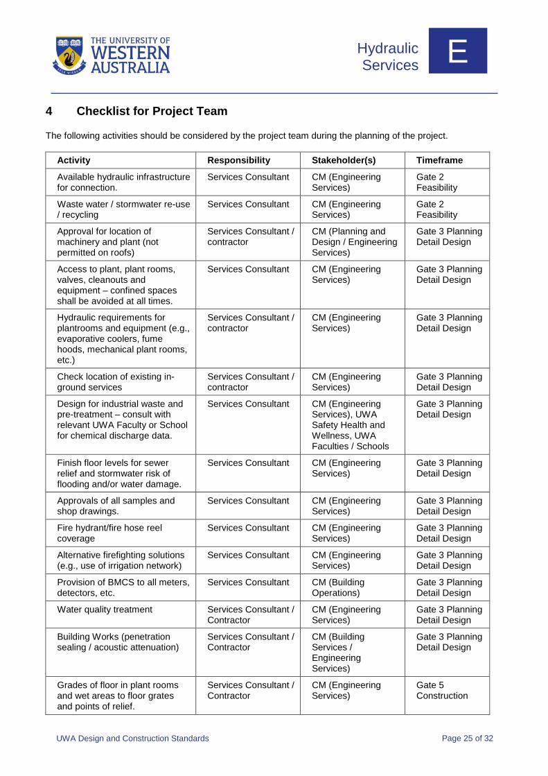
4 Checklist for Project Team
The following activities should be considered by the project team during the planning of the project.
Activity Responsibility Stakeholder(s) Timeframe
Available hydraulic infrastructure for connection.
Services Consultant CM (Engineering Services)
Gate 2 Feasibility
Waste water / stormwater re-use / recycling
Services Consultant CM (Engineering Services)
Gate 2 Feasibility
Approval for location of machinery and plant (not permitted on roofs)
Services Consultant / contractor
CM (Planning and Design / Engineering Services)
Gate 3 Planning Detail Design
Access to plant, plant rooms, valves, cleanouts and equipment – confined spaces shall be avoided at all times.
Services Consultant CM (Engineering Services)
Gate 3 Planning Detail Design
Hydraulic requirements for plantrooms and equipment (e.g., evaporative coolers, fume hoods, mechanical plant rooms, etc.)
Services Consultant / contractor
CM (Engineering Services)
Gate 3 Planning Detail Design
Check location of existing in-ground services
Services Consultant / contractor
CM (Engineering Services)
Gate 3 Planning Detail Design
Design for industrial waste and pre-treatment – consult with relevant UWA Faculty or School for chemical discharge data.
Services Consultant CM (Engineering Services), UWA Safety Health and Wellness, UWA Faculties / Schools
Gate 3 Planning Detail Design
Finish floor levels for sewer relief and stormwater risk of flooding and/or water damage.
Services Consultant CM (Engineering Services)
Gate 3 Planning Detail Design
Approvals of all samples and shop drawings.
Services Consultant CM (Engineering Services)
Gate 3 Planning Detail Design
Fire hydrant/fire hose reel coverage
Services Consultant CM (Engineering Services)
Gate 3 Planning Detail Design
Alternative firefighting solutions (e.g., use of irrigation network)
Services Consultant CM (Engineering Services)
Gate 3 Planning Detail Design
Provision of BMCS to all meters, detectors, etc.
Services Consultant CM (Building Operations)
Gate 3 Planning Detail Design
Water quality treatment Services Consultant / Contractor
CM (Engineering Services)
Gate 3 Planning Detail Design
Building Works (penetration sealing / acoustic attenuation)
Services Consultant / Contractor
CM (Building Services / Engineering Services)
Gate 3 Planning Detail Design
Grades of floor in plant rooms and wet areas to floor grates and points of relief.
Services Consultant / Contractor
CM (Engineering Services)
Gate 5 Construction
Hydraulic Services E
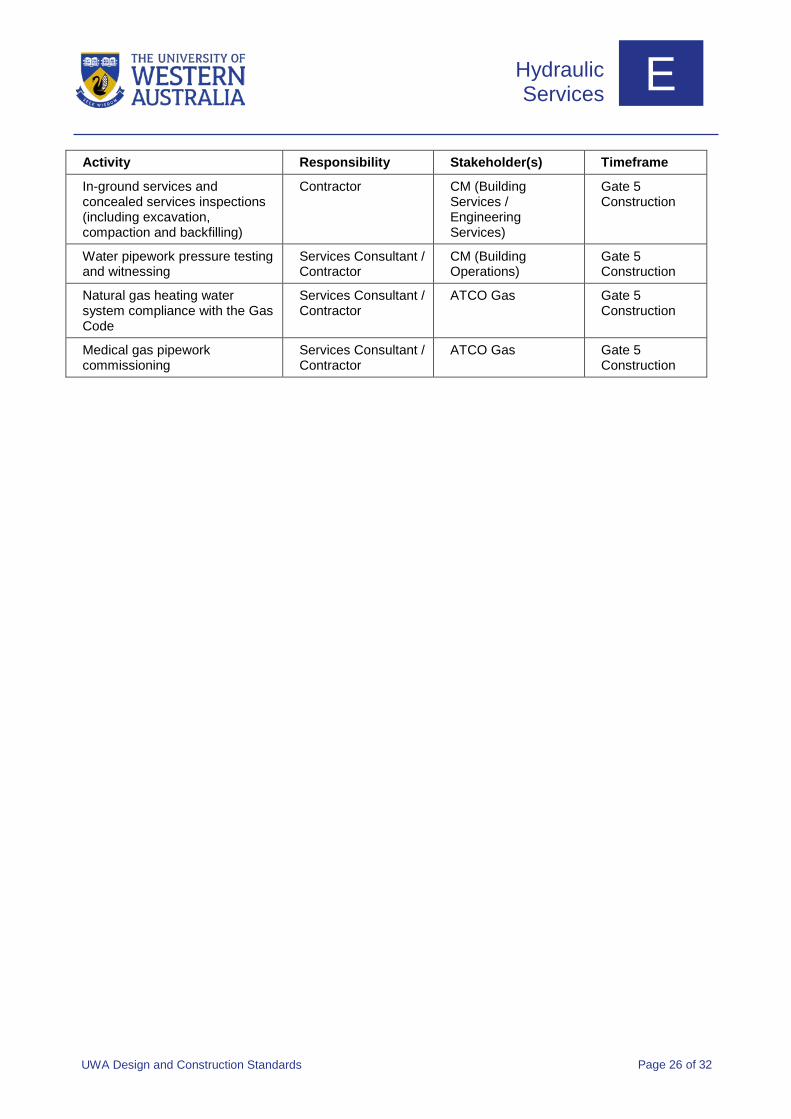
UWA Design and Construction Standards Page 26 of 32
Activity Responsibility Stakeholder(s) Timeframe
In-ground services and concealed services inspections (including excavation, compaction and backfilling)
Contractor CM (Building Services / Engineering Services)
Gate 5 Construction
Water pipework pressure testing and witnessing
Services Consultant / Contractor
CM (Building Operations)
Gate 5 Construction
Natural gas heating water system compliance with the Gas Code
Services Consultant / Contractor
ATCO Gas Gate 5 Construction
Medical gas pipework commissioning
Services Consultant / Contractor
ATCO Gas Gate 5 Construction
Hydraulic Services E
UWA Design and Construction Standards Page 27 of 32
5 Specifications
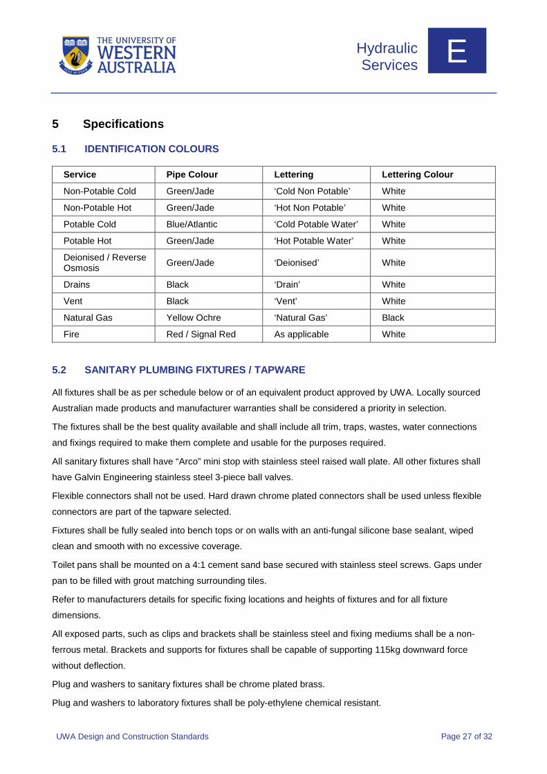
IDENTIFICATION COLOURS 5.1
Service Pipe Colour Lettering Lettering Colour
Non-Potable Cold Green/Jade ‘Cold Non Potable’ White
Non-Potable Hot Green/Jade ‘Hot Non Potable’ White
Potable Cold Blue/Atlantic ‘Cold Potable Water’ White
Potable Hot Green/Jade ‘Hot Potable Water’ White
Deionised / Reverse Osmosis Green/Jade ‘Deionised’ White
Drains Black ‘Drain’ White
Vent Black ‘Vent’ White
Natural Gas Yellow Ochre ‘Natural Gas’ Black
Fire Red / Signal Red As applicable White
SANITARY PLUMBING FIXTURES / TAPWARE 5.2
All fixtures shall be as per schedule below or of an equivalent product approved by UWA. Locally sourced
Australian made products and manufacturer warranties shall be considered a priority in selection.
The fixtures shall be the best quality available and shall include all trim, traps, wastes, water connections
and fixings required to make them complete and usable for the purposes required.
All sanitary fixtures shall have “Arco” mini stop with stainless steel raised wall plate. All other fixtures shall
have Galvin Engineering stainless steel 3-piece ball valves.
Flexible connectors shall not be used. Hard drawn chrome plated connectors shall be used unless flexible
connectors are part of the tapware selected.
Fixtures shall be fully sealed into bench tops or on walls with an anti-fungal silicone base sealant, wiped
clean and smooth with no excessive coverage.
Toilet pans shall be mounted on a 4:1 cement sand base secured with stainless steel screws. Gaps under
pan to be filled with grout matching surrounding tiles.
Refer to manufacturers details for specific fixing locations and heights of fixtures and for all fixture
dimensions.
All exposed parts, such as clips and brackets shall be stainless steel and fixing mediums shall be a non-
ferrous metal. Brackets and supports for fixtures shall be capable of supporting 115kg downward force
without deflection.
Plug and washers to sanitary fixtures shall be chrome plated brass.
Plug and washers to laboratory fixtures shall be poly-ethylene chemical resistant.
Hydraulic Services E
UWA Design and Construction Standards Page 28 of 32
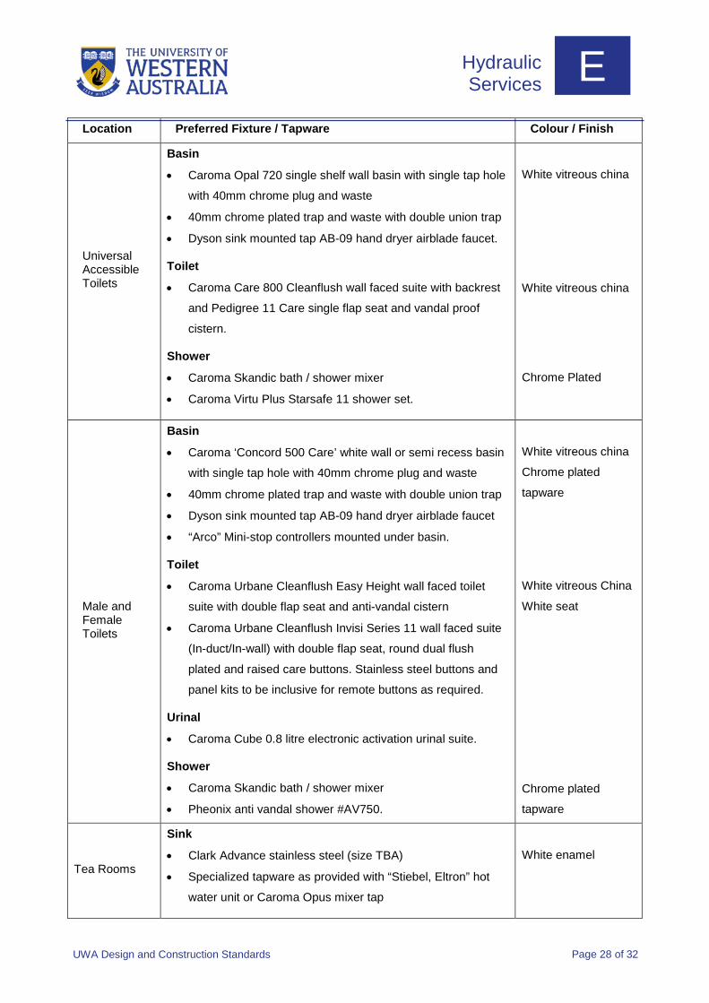
Location Preferred Fixture / Tapware Colour / Finish
Universal Accessible Toilets
Basin
• Caroma Opal 720 single shelf wall basin with single tap hole
with 40mm chrome plug and waste
• 40mm chrome plated trap and waste with double union trap
• Dyson sink mounted tap AB-09 hand dryer airblade faucet.
Toilet
• Caroma Care 800 Cleanflush wall faced suite with backrest
and Pedigree 11 Care single flap seat and vandal proof
cistern.
Shower
• Caroma Skandic bath / shower mixer
• Caroma Virtu Plus Starsafe 11 shower set.
White vitreous china
White vitreous china
Chrome Plated
Male and Female Toilets
Basin
• Caroma ‘Concord 500 Care’ white wall or semi recess basin
with single tap hole with 40mm chrome plug and waste
• 40mm chrome plated trap and waste with double union trap
• Dyson sink mounted tap AB-09 hand dryer airblade faucet
• “Arco” Mini-stop controllers mounted under basin.
Toilet
• Caroma Urbane Cleanflush Easy Height wall faced toilet
suite with double flap seat and anti-vandal cistern
• Caroma Urbane Cleanflush Invisi Series 11 wall faced suite
(In-duct/In-wall) with double flap seat, round dual flush
plated and raised care buttons. Stainless steel buttons and
panel kits to be inclusive for remote buttons as required.
Urinal
• Caroma Cube 0.8 litre electronic activation urinal suite.
Shower
• Caroma Skandic bath / shower mixer
• Pheonix anti vandal shower #AV750.
White vitreous china
Chrome plated
tapware
White vitreous China
White seat
Chrome plated
tapware
Tea Rooms
Sink
• Clark Advance stainless steel (size TBA)
• Specialized tapware as provided with “Stiebel, Eltron” hot
water unit or Caroma Opus mixer tap
White enamel
Hydraulic Services E
UWA Design and Construction Standards Page 29 of 32
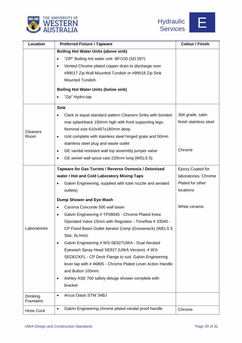
Location Preferred Fixture / Tapware Colour / Finish
Boiling Hot Water Units (above sink)
• “ZIP” Boiling hot water unit- BF/150 (SD 097)
• Vented Chrome plated copper drain to discharge over
#99017 Zip Wall Mounted Tundish or #99018 Zip Sink
Mounted Tundish.
Boiling Hot Water Units (below sink)
• “Zip” Hydro-tap
Cleaners Room
Sink
• Clark or equal standard pattern Cleaners Sinks with bonded
rear splashback 150mm high with front supporting legs.
Nominal size 610x457x180mm deep.
• Unit complete with stainless steel hinged grate and 50mm
stainless steel plug and waste outlet
• GE vandal resistant wall top assembly jumper valve
• GE swivel wall spout cast 225mm long (WELS 5)
304 grade, satin
finish stainless steel
Chrome
Laboratories
Tapware for Gas Turrets / Reverse Osmosis / Deionised water / Hot and Cold Laboratory Mixing Taps
• Galvin Engineering, supplied with tube nozzle and aerated
outlets)
Dump Shower and Eye Wash
• Caroma Concorde 500 wall basin
• Galvin Engineering # TP08045 - Chrome Plated Knee
Operated Valve 15mm with Regulator - Timeflow # 33540 -
CP Fixed Basin Outlet Aerator Comp (Gooseneck) (WELS 5
Star, 6L/min).
• Galvin Engineering # WS-SE927UWA - Dual Aerated
Eyewash Spray Head SE927 (UWA Version). # WS-
SEDECKFL - CP Deck Flange to suit. Galvin Engineering
lever tap with # 46805 - Chrome Plated Lever Action Handle
and Button 100mm.
• Ashley ASE 700 safety deluge shower complete with
bracket
Epoxy Coated for
laboratories. Chrome
Plated for other
locations
White ceramic
Drinking Fountains
• Arcus Oasis STW 34BJ
Hose Cock • Galvin Engineering chrome plated vandal proof handle Chrome
Hydraulic Services E
UWA Design and Construction Standards Page 30 of 32
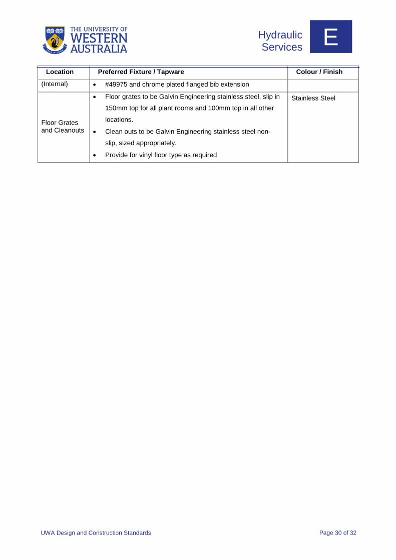
Location Preferred Fixture / Tapware Colour / Finish
(Internal) • #49975 and chrome plated flanged bib extension
Floor Grates and Cleanouts
• Floor grates to be Galvin Engineering stainless steel, slip in
150mm top for all plant rooms and 100mm top in all other
locations.
• Clean outs to be Galvin Engineering stainless steel non-
slip, sized appropriately.
• Provide for vinyl floor type as required
Stainless Steel

Hydraulic Services E
UWA Design and Construction Standards Page 31 of 32
Abbreviations
AGA Australian Gas Association
ASME American Society of Mechanical Engineers
BIC British Instantaneous Couplings
BMCS Building Management and Control Systems
DDA Disability Discrimination Act
DFES Department of Fire and Emergency Services
DWV Drain, waste and vent
FGL Finish Ground Level
GE General Electric
GWI Galvanised wrought iron
HDPE High density poly ethylene
NCC National Construction Code
OPSO Over pressure shut off
PLB Plumbers Licensing Board
PVC Polyvinyl chloride
RO Reverse osmosis
RPZD Reduced pressure zone devices
TMV Thermostatic mixing valves
UV Ultraviolet
UWA the University of Western Australia
WC Water Corporation
WELS Water Efficiency Labelling and Standards
Hydraulic Services E
UWA Design and Construction Standards Page 32 of 32
References
AS/NZS 1221 Fire hose reels
AS 1345 Identification of the contents of pipes, conduits and ducts
AS/NZS 1428 Design for access and mobility
AS 1432 Copper tubes for plumbing, gasfitting and drainage applications
AS 1851 Routine service of fire protection systems and equipment
AS/NZS 2243 Safety in laboratories
AS 2419 Fire hydrant installations
AS 2441 Installation of fire hose reels
AS/NZS 2845 Water supply- backflow prevention devices
AS/NZS 2982 Laboratory design and construction
AS/NZS 3500 Plumbing and drainage
AS 3814 Industrial and commercial gas-fired appliances (supersedes AG 501)
AS 4775 Emergency eyewash and shower equipment
AS 5601 Gas installations (supersedes AG 601)
Australian Guidelines for Certification of Physical Containment
Australian Quarantine and Inspection Services
Department of Fire and Emergency Services
National Construction Code
Radiological Council
Water Corporation Plumbing By-laws

Campus Management
The University of Western Australia M458, Perth WA 6009 Tel: +61 8 6488 2025 cm.uwa.edu.au