Embed Size (px)
Citation preview
Purdue UniversityPurdue e-Pubs
International Compressor Engineering Conference School of Mechanical Engineering
2006
The Use of CAD/CAE Tools in CompressorDevelopment Focusing Structural AnalysisRinaldo PuffEmbraco S.A.
Marcos Dropa del BortoliEmbraco S.A.
Raul BoscoEmbraco S.A.
Eduardo L. GaertnerEmbraco S.A.
Follow this and additional works at: https://docs.lib.purdue.edu/icec
This document has been made available through Purdue e-Pubs, a service of the Purdue University Libraries. Please contact [email protected] foradditional information.Complete proceedings may be acquired in print and on CD-ROM directly from the Ray W. Herrick Laboratories at https://engineering.purdue.edu/Herrick/Events/orderlit.html
Puff, Rinaldo; Bortoli, Marcos Dropa del; Bosco, Raul; and Gaertner, Eduardo L., "The Use of CAD/CAE Tools in CompressorDevelopment Focusing Structural Analysis" (2006). International Compressor Engineering Conference. Paper 1736.https://docs.lib.purdue.edu/icec/1736
C149, Page 1
International Compressor Engineering Conference at Purdue, July 17-20, 2006
The Use of CAD/CAE Tools in Compressor Development Focusing StructuralAnalysis
Rinaldo Puff 1, Marcos Giovani Dropa de Bortoli 2, Raul Bosco Jr.3, Eduardo L. Gaertner 4
Embraco, Empresa Brasileira de Compressores S.A., GTPPJoinville, S.C., Brazil
1++55 47 3441 2044, [email protected]++55 47 3441 2783, [email protected]++55 47 3441 2679, [email protected]++55 47 3441 2053, [email protected]
ABSTRACT
Considering the current market environment, where competition can not be denied and the development time mustbe even short than ever, the use of advanced engineering tools is mandatory. New products must reach the market assoon as possible otherwise the opportunity will be left for the competitors. Furthermore, the cost reduction approachduring the design is a mandatory effort and must be considered. Concerning those issues, advanced CAE tools haveimportant duty to accomplish this requirement. Using virtual models created by CAD system and commercial or in-house engineering software (CAE), mainly Finite Element Method (FEM), it is possible to simulate the structuralbehavior of a mechanical component before its prototyping. Prototypes have high cost in terms of money, time andproduction. The objective of this work is to present some FEM applications on compressor components, showing itsimportance and power in the development of this kind of product.
1. INTRODUCTION
In an industrial area with high level of competition, as it is the case of household and commercial refrigeration, thecontinuous technological development has capital influence in the companies survival. Due to the high investment inglobal markets, and as a rule, with a big demand in terms of efficiency, reliability, robustness, low noise andvibration, the conscience and concern about such reality, are factor that has delineated the success of manycompanies. Several faces of the continuous technological qualification process could be explored. However, thetarget of what is presented here restricts to the topics related to the new products development and the current onesoptimization, in a typical scene of applied research. Obviously, it does not discard incursions in the basic researchfield aiming the critical mass increase. In this aspect, one can see how valuable have become the technicalcooperation agreements made with universities. To achieve the very high level of competition, characteristics ofsmall size and light weight are continuously required for the compressors applied in the above mentionedapplication. On the other hand, there is the requirement of absolute reliability and robustness. The final user expectsabsolutely no maintenance, and so the very best compromise between these two main characteristics (light weightand small size versus reliability and robustness) need to be achieved. With the application of CAD/CAE tools, andhere we will focus on the Finite Element Method (FEM) technique, one may be able to perform the optimizationlooping in the very early phase of the projects, and so reduce the expenditure with prototyping and experimentaltesting. In order to increase the expertise in the mentioned technique, during the mid 80’s several FEM courses hadbeen taken in-company, with the support of a technical agreement with a university. After a period of initialactivities, some specific works had been performed resulting in some hints about components reliability, mainlyrestricted to some few parts like the shaft, valves and discharge tube. In a posterior phase, at this time with morepowerful computational resources, a CAD system and terminals with graphic capabilities, an in house software for
C149, Page 2
International Compressor Engineering Conference at Purdue, July 17-20, 2006
general purposes called “DOCTUS” (Heinzelmann et al., 1989a, 1989b) was developed. This program was able toexecute linear analysis, static and dynamic of structures, beyond the development of expertise in this area. The maincontribution of this software was its application as a tool during the development of a compressor housing withgains in noise reduction, during the development of HFC compressors, in the early 90’s (de Bortoli, 1992). The nextstep was the acquisition of a commercial software, with capabilities for nonlinear analysis and fluid-structureinteraction, in order to increase the possibilities of simulation. Optimization methods integrating all the developmentcycle in a mathematical model were also developed (de Bortoli and Puff, 1998). Experimental methods are in thesame way very important in the components structural evaluation, and so far were internally developed (Gaertnerand de Bortoli, 2006). Some examples are: fatigue testing; the measuring of natural frequencies and vibrationmodes; and also techniques for stress and strain measurements.
2. CAD x CAE INTEGRATION
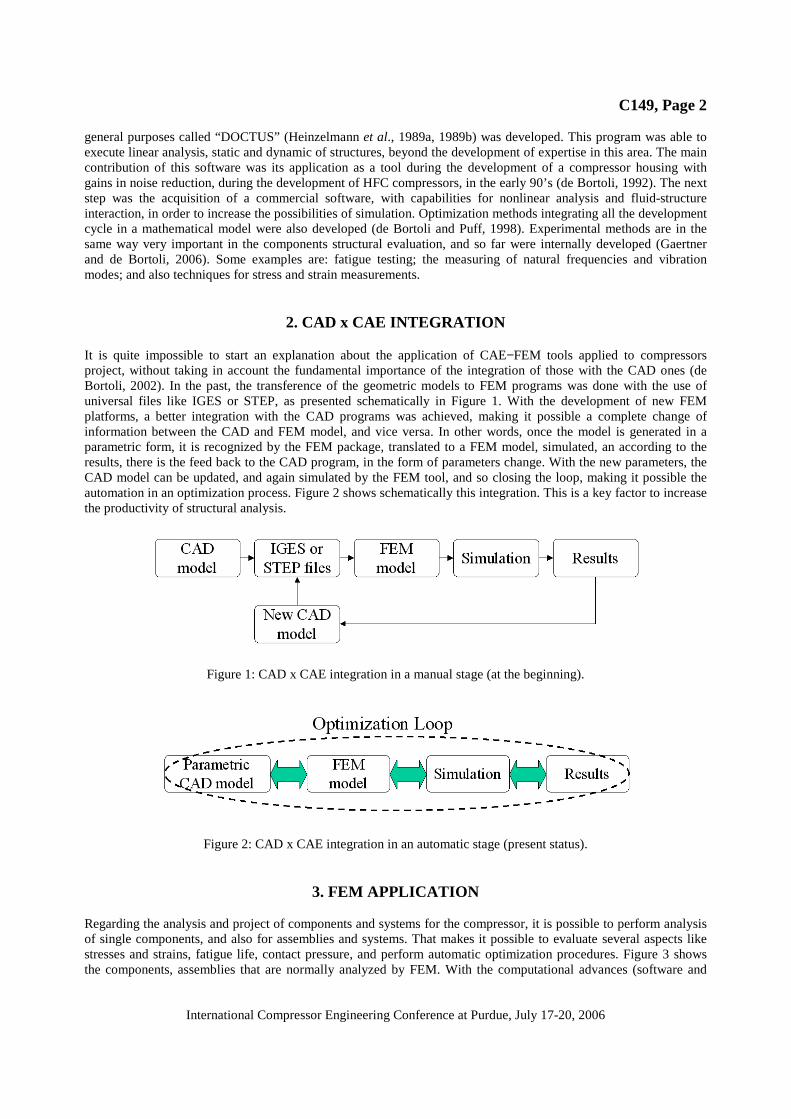
It is quite impossible to start an explanation about the application of CAE−FEM tools applied to compressorsproject, without taking in account the fundamental importance of the integration of those with the CAD ones (deBortoli, 2002). In the past, the transference of the geometric models to FEM programs was done with the use ofuniversal files like IGES or STEP, as presented schematically in Figure 1. With the development of new FEMplatforms, a better integration with the CAD programs was achieved, making it possible a complete change ofinformation between the CAD and FEM model, and vice versa. In other words, once the model is generated in aparametric form, it is recognized by the FEM package, translated to a FEM model, simulated, an according to theresults, there is the feed back to the CAD program, in the form of parameters change. With the new parameters, theCAD model can be updated, and again simulated by the FEM tool, and so closing the loop, making it possible theautomation in an optimization process. Figure 2 shows schematically this integration. This is a key factor to increasethe productivity of structural analysis.
Figure 1: CAD x CAE integration in a manual stage (at the beginning).
Figure 2: CAD x CAE integration in an automatic stage (present status).
3. FEM APPLICATION
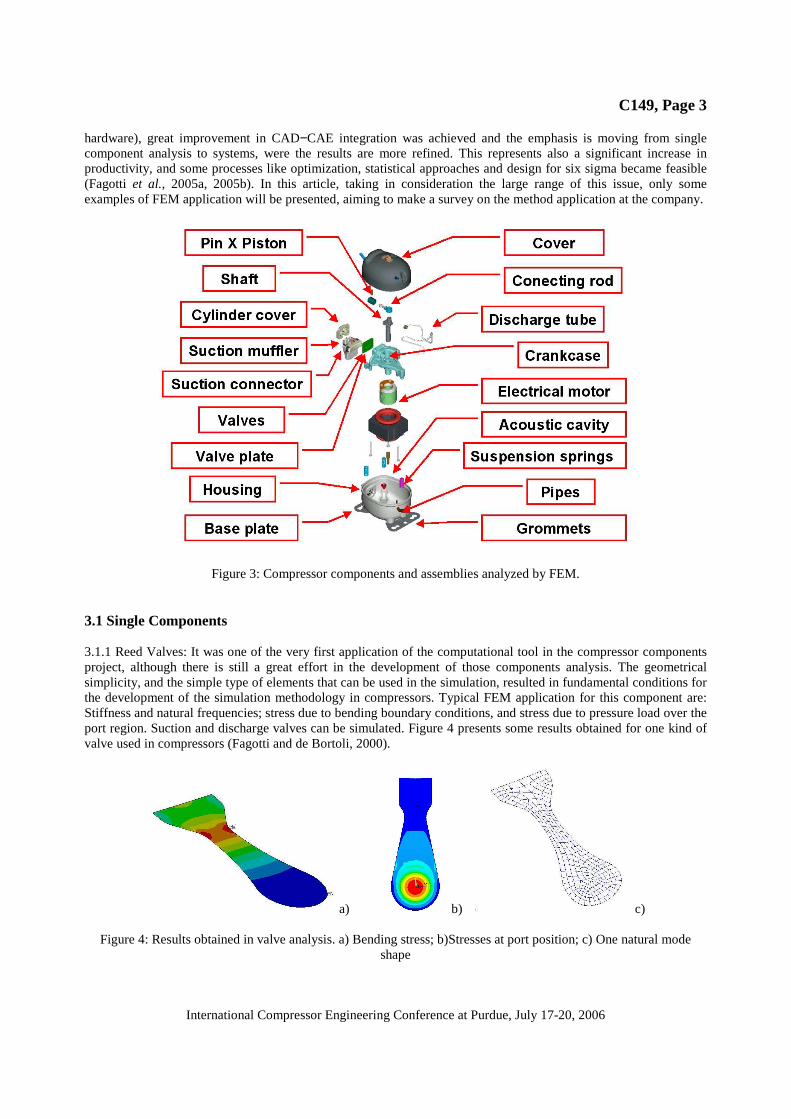
Regarding the analysis and project of components and systems for the compressor, it is possible to perform analysisof single components, and also for assemblies and systems. That makes it possible to evaluate several aspects likestresses and strains, fatigue life, contact pressure, and perform automatic optimization procedures. Figure 3 showsthe components, assemblies that are normally analyzed by FEM. With the computational advances (software and
C149, Page 3
International Compressor Engineering Conference at Purdue, July 17-20, 2006
hardware), great improvement in CAD−CAE integration was achieved and the emphasis is moving from singlecomponent analysis to systems, were the results are more refined. This represents also a significant increase inproductivity, and some processes like optimization, statistical approaches and design for six sigma became feasible(Fagotti et al., 2005a, 2005b). In this article, taking in consideration the large range of this issue, only someexamples of FEM application will be presented, aiming to make a survey on the method application at the company.
Figure 3: Compressor components and assemblies analyzed by FEM.
3.1 Single Components
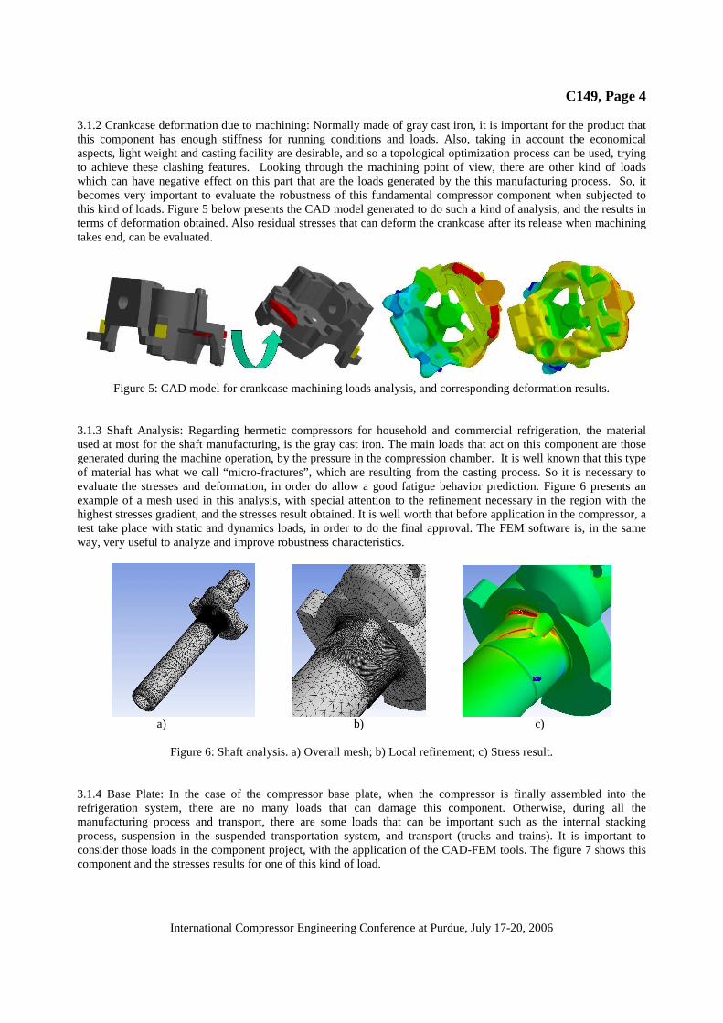
3.1.1 Reed Valves: It was one of the very first application of the computational tool in the compressor componentsproject, although there is still a great effort in the development of those components analysis. The geometricalsimplicity, and the simple type of elements that can be used in the simulation, resulted in fundamental conditions forthe development of the simulation methodology in compressors. Typical FEM application for this component are:Stiffness and natural frequencies; stress due to bending boundary conditions, and stress due to pressure load over theport region. Suction and discharge valves can be simulated. Figure 4 presents some results obtained for one kind ofvalve used in compressors (Fagotti and de Bortoli, 2000).
a) b) c)
Figure 4: Results obtained in valve analysis. a) Bending stress; b)Stresses at port position; c) One natural modeshape
C149, Page 4
International Compressor Engineering Conference at Purdue, July 17-20, 2006
3.1.2 Crankcase deformation due to machining: Normally made of gray cast iron, it is important for the product thatthis component has enough stiffness for running conditions and loads. Also, taking in account the economicalaspects, light weight and casting facility are desirable, and so a topological optimization process can be used, tryingto achieve these clashing features. Looking through the machining point of view, there are other kind of loadswhich can have negative effect on this part that are the loads generated by the this manufacturing process. So, itbecomes very important to evaluate the robustness of this fundamental compressor component when subjected tothis kind of loads. Figure 5 below presents the CAD model generated to do such a kind of analysis, and the results interms of deformation obtained. Also residual stresses that can deform the crankcase after its release when machiningtakes end, can be evaluated.
Figure 5: CAD model for crankcase machining loads analysis, and corresponding deformation results.
3.1.3 Shaft Analysis: Regarding hermetic compressors for household and commercial refrigeration, the materialused at most for the shaft manufacturing, is the gray cast iron. The main loads that act on this component are thosegenerated during the machine operation, by the pressure in the compression chamber. It is well known that this typeof material has what we call “micro-fractures”, which are resulting from the casting process. So it is necessary toevaluate the stresses and deformation, in order do allow a good fatigue behavior prediction. Figure 6 presents anexample of a mesh used in this analysis, with special attention to the refinement necessary in the region with thehighest stresses gradient, and the stresses result obtained. It is well worth that before application in the compressor, atest take place with static and dynamics loads, in order to do the final approval. The FEM software is, in the sameway, very useful to analyze and improve robustness characteristics.
a) b) c)
Figure 6: Shaft analysis. a) Overall mesh; b) Local refinement; c) Stress result.
3.1.4 Base Plate: In the case of the compressor base plate, when the compressor is finally assembled into therefrigeration system, there are no many loads that can damage this component. Otherwise, during all themanufacturing process and transport, there are some loads that can be important such as the internal stackingprocess, suspension in the suspended transportation system, and transport (trucks and trains). It is important toconsider those loads in the component project, with the application of the CAD-FEM tools. The figure 7 shows thiscomponent and the stresses results for one of this kind of load.

C149, Page 5
International Compressor Engineering Conference at Purdue, July 17-20, 2006
Figure 7: Base plate model and stress result.
3.1.5 Discharge tube: This is a very important component with special characteristics. It communicates the cylindercover with the compressor housing, conducting the compressed refrigerant from the first to the latter. It is wellknown that the mechanical kit is suspended inside the housing by suspension springs and has relative movements.The vibration generated by the eccentric masses during the compressor operation can not be transferred to thehousing. So the tube needs to have a certain flexibility, and due to this flexibility, natural frequencies become low,near the operation frequency, 50 or 60Hz. FEM analysis is a powerful manner for designing this part with naturalfrequencies that are not coincident with the operation ones. Also in transportation, the relative movement betweenthe mechanical kit and the housing is a stress source for this component. Also in this case, FEM is a huge tool toevaluate stresses concentration points, and provide means to redesign the component and avoid this effect. Figure 8below shows a discharge tube stress result for one kind of load.
Figure 8: Stress distribution in a discharge tube subjected to one kind of load.
3.1.6 Suction connector: Hyper-elastic components simulation is a brand new area of high nonlinear analysis. In thecompressor there are at least four different parts made of rubber, like the grommets, pipe lugs, discharge tubedamper and the suction connector. This latter, is used to conduct the refrigerating gas from the suction pipe directlyto the suction muffler avoiding heating and improving volumetric efficiency. For a good performance, there is aneed of a correct deformation behavior, and an adequate contact force against the housing. Prototyping this kind ofcomponent is very expensive, with the need of dies for each new configuration, and the try and test method becomescostly. The use of the FEM methodology brought gains is project velocity and cost reduction. Figure 9 shows asuction connector, and its deformation result.
Figure 9: Suction connector model and deformation result.
C149, Page 6
International Compressor Engineering Conference at Purdue, July 17-20, 2006
3.2 Assemblies and Systems
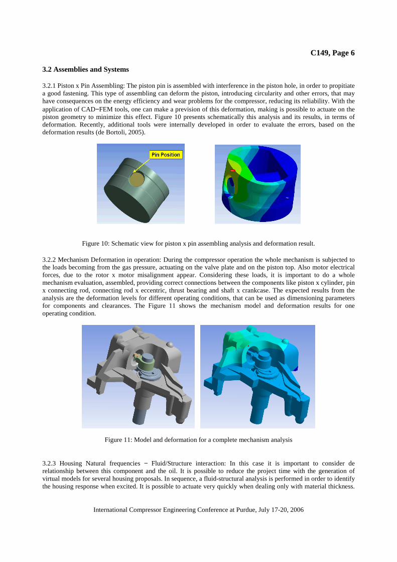
3.2.1 Piston x Pin Assembling: The piston pin is assembled with interference in the piston hole, in order to propitiatea good fastening. This type of assembling can deform the piston, introducing circularity and other errors, that mayhave consequences on the energy efficiency and wear problems for the compressor, reducing its reliability. With theapplication of CAD−FEM tools, one can make a prevision of this deformation, making is possible to actuate on thepiston geometry to minimize this effect. Figure 10 presents schematically this analysis and its results, in terms ofdeformation. Recently, additional tools were internally developed in order to evaluate the errors, based on thedeformation results (de Bortoli, 2005).
Figure 10: Schematic view for piston x pin assembling analysis and deformation result.
3.2.2 Mechanism Deformation in operation: During the compressor operation the whole mechanism is subjected tothe loads becoming from the gas pressure, actuating on the valve plate and on the piston top. Also motor electricalforces, due to the rotor x motor misalignment appear. Considering these loads, it is important to do a wholemechanism evaluation, assembled, providing correct connections between the components like piston x cylinder, pinx connecting rod, connecting rod x eccentric, thrust bearing and shaft x crankcase. The expected results from theanalysis are the deformation levels for different operating conditions, that can be used as dimensioning parametersfor components and clearances. The Figure 11 shows the mechanism model and deformation results for oneoperating condition.
Figure 11: Model and deformation for a complete mechanism analysis
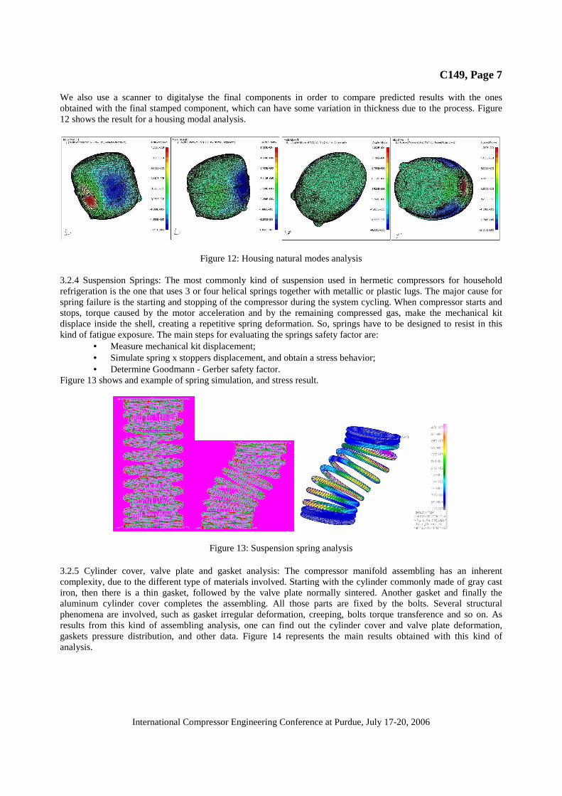
3.2.3 Housing Natural frequencies − Fluid/Structure interaction: In this case it is important to consider derelationship between this component and the oil. It is possible to reduce the project time with the generation ofvirtual models for several housing proposals. In sequence, a fluid-structural analysis is performed in order to identifythe housing response when excited. It is possible to actuate very quickly when dealing only with material thickness.
C149, Page 7
International Compressor Engineering Conference at Purdue, July 17-20, 2006
We also use a scanner to digitalyse the final components in order to compare predicted results with the onesobtained with the final stamped component, which can have some variation in thickness due to the process. Figure12 shows the result for a housing modal analysis.
Figure 12: Housing natural modes analysis
3.2.4 Suspension Springs: The most commonly kind of suspension used in hermetic compressors for householdrefrigeration is the one that uses 3 or four helical springs together with metallic or plastic lugs. The major cause forspring failure is the starting and stopping of the compressor during the system cycling. When compressor starts andstops, torque caused by the motor acceleration and by the remaining compressed gas, make the mechanical kitdisplace inside the shell, creating a repetitive spring deformation. So, springs have to be designed to resist in thiskind of fatigue exposure. The main steps for evaluating the springs safety factor are:
• Measure mechanical kit displacement;• Simulate spring x stoppers displacement, and obtain a stress behavior;• Determine Goodmann - Gerber safety factor.
Figure 13 shows and example of spring simulation, and stress result.
Figure 13: Suspension spring analysis
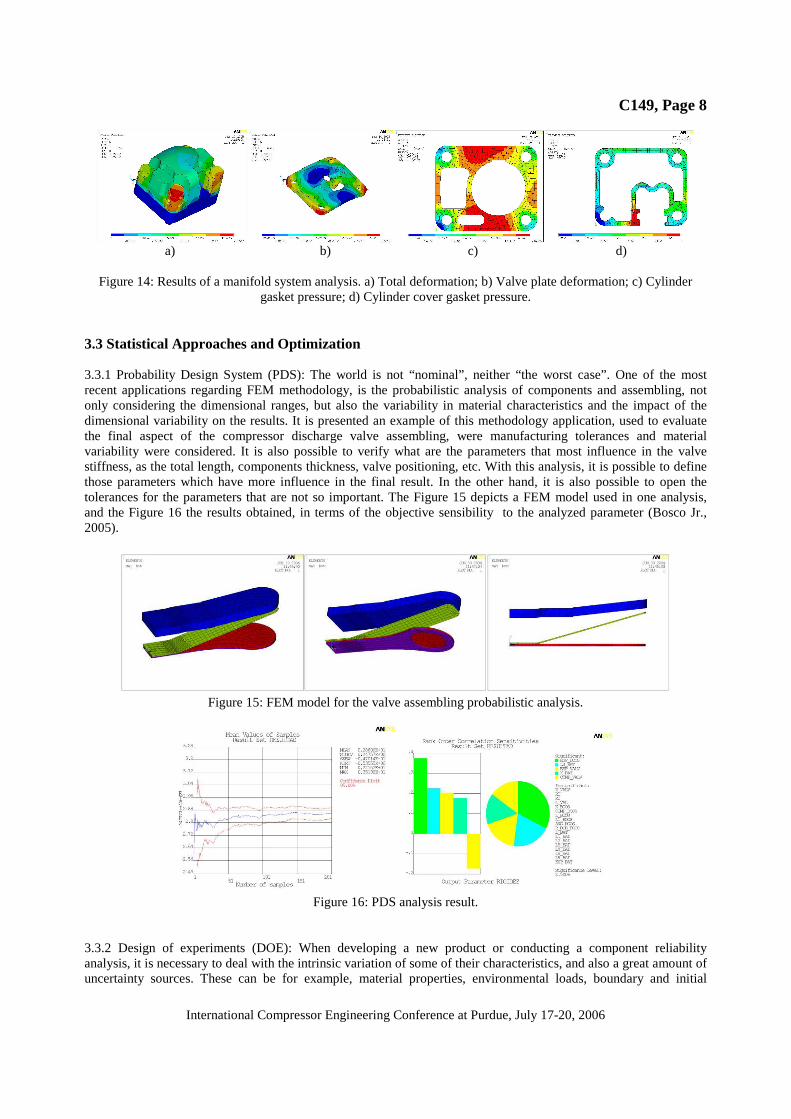
3.2.5 Cylinder cover, valve plate and gasket analysis: The compressor manifold assembling has an inherentcomplexity, due to the different type of materials involved. Starting with the cylinder commonly made of gray castiron, then there is a thin gasket, followed by the valve plate normally sintered. Another gasket and finally thealuminum cylinder cover completes the assembling. All those parts are fixed by the bolts. Several structuralphenomena are involved, such as gasket irregular deformation, creeping, bolts torque transference and so on. Asresults from this kind of assembling analysis, one can find out the cylinder cover and valve plate deformation,gaskets pressure distribution, and other data. Figure 14 represents the main results obtained with this kind ofanalysis.
C149, Page 8
International Compressor Engineering Conference at Purdue, July 17-20, 2006
a) b) c) d)
Figure 14: Results of a manifold system analysis. a) Total deformation; b) Valve plate deformation; c) Cylindergasket pressure; d) Cylinder cover gasket pressure.
3.3 Statistical Approaches and Optimization
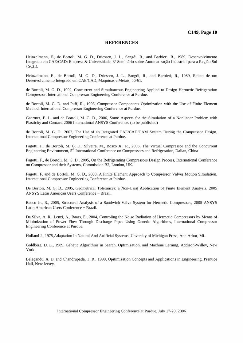
3.3.1 Probability Design System (PDS): The world is not “nominal”, neither “the worst case”. One of the mostrecent applications regarding FEM methodology, is the probabilistic analysis of components and assembling, notonly considering the dimensional ranges, but also the variability in material characteristics and the impact of thedimensional variability on the results. It is presented an example of this methodology application, used to evaluatethe final aspect of the compressor discharge valve assembling, were manufacturing tolerances and materialvariability were considered. It is also possible to verify what are the parameters that most influence in the valvestiffness, as the total length, components thickness, valve positioning, etc. With this analysis, it is possible to definethose parameters which have more influence in the final result. In the other hand, it is also possible to open thetolerances for the parameters that are not so important. The Figure 15 depicts a FEM model used in one analysis,and the Figure 16 the results obtained, in terms of the objective sensibility to the analyzed parameter (Bosco Jr.,2005).
Figure 15: FEM model for the valve assembling probabilistic analysis.
Figure 16: PDS analysis result.
3.3.2 Design of experiments (DOE): When developing a new product or conducting a component reliabilityanalysis, it is necessary to deal with the intrinsic variation of some of their characteristics, and also a great amount ofuncertainty sources. These can be for example, material properties, environmental loads, boundary and initial

C149, Page 9
International Compressor Engineering Conference at Purdue, July 17-20, 2006
conditions, geometry and assembling imperfections and geometric, shape and position tolerances. Moreover, most ofthe computer aided analysis procedures could also lay on a scatter of variations concerning to its solver, computertruncation, element type choice by the analyst, contact algorithm, mesh type and so on. Design of experiments(DOE) is a systematic method for the determination of the model’s sensitivity to those variations. The first step isthe specification of the design variables whose sensitivity to variation is to be gauged and then run the DOE. Duringthe DOE, the FEM tool runs several simulations changing the values of the design variables and measures the effectof the changes on the outcome. In the virtual field, it can be also called “Virtual Experiments”. DOE (also calledexperimental design) is a collection of procedures and statistical tools for planning experiments and analyzing theresults. DOE techniques can improve the understanding of the design, increase the reliability of the conclusions, andoften get a faster answer than trial-and-error experimentation.
3.3.3 Optimization: The automation of the analysis, with the use of parametric models, aiming the minimization ormaximization of one special characteristic is so called optimization. Several packages, with different routines havebeen developed in the last years, and its application in compressor components design is becoming more and morefrequent and very helpful. One method for optimization is the “Sub-problem Approximation”, which is an advancedzero-order method that uses approximations (curve fitting) to all dependent variables. Other methodology is the“First Order”, that uses derivative information, that is, gradients of the dependent variables with respect to thedesign variables. It is highly accurate and works well for problems having dependent variables that vary widely overa large range of design space. However, this method can be computationally intense (de Bortoli and Puff, 1998).Finally, the brand new methodology in use, is the Genetic Algorithm (GA), that have been applied to optimizationproblems in several engineering applications, and also in compressors (da Silva et al., 2004). It is based on theDarwin’s natural evolution and selection, and was first proposed by John Holland in the middle 60’s (Holland,1975). The efficiency of the optimization by the GA involves the challenge of finding populations with the bestfitness. Which can evolve and survive for many generations. GA are formulated in order to find global optimums(maximums or minimums) into discontinuous spaces and multi-modals, without the necessity of initiating theprocess with a good initial try (Goldberg, 1989) (Belegandu and Chandrupatla, 1999).
4. CONCLUDING REMARKS
After quite twenty years of activity in FEM, there are very few compressor components that had not been analyzedby this technique. Our experience in this area have proved during this time that the application of theCAD−CAE/FEM programs can bring significant advantages when correctly applied in the design of compressorcomponents. It is not a “black box”, an like it, it can never be considered. Users of FEM tools and also other CAEmethodologies need to have minimum knowledge about the involved mathematical theory, and its limitations. Ifwrong inputs are given to the program, in terms of loads, boundary conditions and material properties, certainly theprograms will outcome with wrong results. There are several challenges that specialists in FEM need also to beaware about. One of them is the cost/benefit relation. Considering that in the modeling, simplifications sometimeshave to be done, there is no necessity of meshes with thousands and thousands of nodes and elements. What have tobe done is only the necessary for a reliable result. Nothing more and nothing less. Other big challenge is the sourceof good material properties. One can find in bibliographic references, ore also in several internet sites, averagematerial properties. But depending on the deepness of the analysis that has to be conducted, it is well worth to makesome preliminary material evaluations. Statistical and probabilistic analysis is the third challenge. It is no morepossible to consider only nominal dimensions and average material properties. Manufacturing tolerances arebecoming more and more tighter, and it is very important do determine which are really important for thecomponent and/or system, and which are not. This correct evaluation, can lead to an cost/benefit optimized process,reducing investments and lowering costs. Finally, as said at the beginning of this article, customers are looking moreand more for better products, with lower energy requirements lower sound and vibration levels, lighter weight andsmaller size, without compromising reliability and robustness. Taking in account all those requirements, it is verydifficult to imagine future simulation scenarios without increasing more and more the integration between CAD,FEM, CFD − Computed Fluid Dynamics and Noise evaluation packages, preferably in an unique environment.
C149, Page 10
International Compressor Engineering Conference at Purdue, July 17-20, 2006
REFERENCES
Heinzelmann, E., de Bortoli, M. G. D., Driessen, J. L., Sangói, R., and Barbieri, R., 1989, DesenvolvimentoIntegrado em CAE/CAD: Empresa & Universidade, 3º Seminário sobre Automatização Industrial para a Região Sul/ SC(I).
Heinzelmann, E., de Bortoli, M. G. D., Driessen, J. L., Sangói, R., and Barbieri, R., 1989, Relato de umDesenvolvimento Integrado em CAE/CAD, Máquinas e Metais, 56-61.
de Bortoli, M. G. D., 1992, Concurrent and Simultaneous Engineering Applied to Design Hermetic RefrigerationCompressor, International Compressor Engineering Conference at Purdue.
de Bortoli, M. G. D. and Puff, R., 1998, Compressor Components Optimization with the Use of Finite ElementMethod, International Compressor Engineering Conference at Purdue.
Gaertner, E. L. and de Bortoli, M. G. D., 2006, Some Aspects for the Simulation of a Nonlinear Problem withPlasticity and Contact, 2006 International ANSYS Conference. (to be published)
de Bortoli, M. G. D., 2002, The Use of an Integrated CAE/CAD/CAM System During the Compressor Design,International Compressor Engineering Conference at Purdue.
Fagotti, F., de Bortoli, M. G. D., Silveira, M., Bosco Jr., R., 2005, The Virtual Compressor and the ConcurrentEngineering Environment, 5th International Conference on Compressors and Refrigeration, Dalian, China
Fagotti, F., de Bortoli, M. G. D., 2005, On the Refrigerating Compressors Design Process, International Conferenceon Compressor and their Systems, Commission B2, London, UK.
Fagotti, F. and de Bortoli, M. G. D., 2000, A Finite Element Approach to Compressor Valves Motion Simulation,International Compressor Engineering Conference at Purdue.
De Bortoli, M. G. D., 2005, Geometrical Tolerances: a Non-Usial Application of Finite Element Analysis, 2005ANSYS Latin American Users Conference − Brazil.
Bosco Jr., R., 2005, Structural Analysis of a Sandwich Valve System for Hermetic Compressors, 2005 ANSYSLatin American Users Conference − Brazil.
Da Silva, A. R., Lenzi, A., Baars, E., 2004, Controling the Noise Radiation of Hermetic Compressors by Means ofMinimization of Power Flow Through Discharge Pipes Using Genetic Algorithms, International CompressorEngineering Conference at Purdue.
Holland J., 1975,Adaptation In Natural And Artificial Systems, Unversity of Michigan Press, Ann Arbor, Mi.
Goldberg, D. E., 1989, Genetic Algorithms in Search, Optimization, and Machine Lerning, Addison-Willey, NewYork.
Belegandu, A. D. and Chandrupatla, T. R., 1999, Opitimization Concepts and Applications in Engineering, PrenticeHall, New Jersey.


![[CAD CAM CAE] Ansys - Userguide](https://img.pdfslide.net/doc/110x75/543e0826b1af9f1f2b8b45c7/cad-cam-cae-ansys-userguide.jpg)