Embed Size (px)
Citation preview
THE USE OF COLLIMATORS FOR TESTINGAND ADlUSTING INSTRUMENTS*
E. M. MedlenGeodetic Service of Canada
T HERE is an old saying, "A poor workman blames his tools," but it mightalso be said that no matter how proficient the workman, the results of his
labours will depend to a certain extent upon the equipment he uses. For theengineer engaged upon work of high precision, modern science has createdmasterpieces of mechanical skill. The surveyor can now measure angles withan instrument which reads by estimation to a tenth of a second of arc and whichis so finely fitted that the tolerance between certain moving parts is only a fewten-thousandths of an inch. The instrument maker has done his part, but inorder that the equipment may function with maximum efficiency it is essentialthat it be kept in perfect condition and subject to frequent tests. For this purpose, field methods are frequently inadequate. They have been superseded bythe laboratory equipment where, working under ideal conditions, it is possibleto detect the smallest inaccuracy, diagnose the particular trouble, and makethose fine adjustments which alone assure perfect operation.
Canada's need for a workshop of this nature was realized many years ago,but it was not until 1911 that the late Dr. E. E. Deville succeeded in havingone built. The Doctor, who at that time was Surveyor General of DominionLands, demanded accurate work from his surveyors, but he knew that to obtainthat result they must be supplied with instrumental equipment of precision.A special building was erected for the sole purpose of testing and adjustinginstruments, and his wisdom and foresight have been amply proved by theever increasing demands made by Departments of Government for variouslaboratory checks. To-day, in the National Research Building, Canada canboast of a department which was specially equipped for the handling of all suchproblems.
For the general testing of theodolites, the equipment is fairly simple, consisting in the main of a required number of collimators mounted on piers placedon the semi-circumference of a circle, of which the pier supporting the instrument to be tested forms the centre. A spacing which proved very satisfactoryconsisted of having two collimators 180° apart, and a third 60° from one ofthem. For further tests, a vertical collimator or one at an angle of 45° above thehorizontal plane may be used to advantage.
The laboratory in which this equipment is used must, however, meet certainvery definite requirements. It should be so located that the temperature will bealmost constant and not subject to sudden changes. Supports for both collimators and instrument should be of solid construction with the foundations onbedrock. The collimator room used by the Canadian Geodetic Service is situatedin the sub-basement, the collimators and instrument are supported on concretepillars free from the walls, the daily temperature range is less than 2°, and theangular spacing of the collimators does not change by more than 2 seconds perweek. The necessity of these precautions can easily be seen when it is realizedthat in making laboratory tests all external causes of trouble must be eliminatedas far as possible, and the records obtained should give a true picture of thf>operation of the instrument.
As to the collimators themselves, although telescopes designed particularly* Presented at the Annual Meeting of the Society.
13

14 PHOTOGRAMMETRIC ENGINEERING
for collimator service have certain advantages, any theodolite or level with agood telescope can be adapted for the purpose. Excellent results have beenobtained in Canada by using old style 12-inch theodolites, the whole assemblybeing mounted on the pier.
The illumination and definition of the collimator cross-hairs is very important. Satisfactory results may be obtained by removing the eyepiece and substituting a small cylinder with an aperture of 1/50 inch diameter, adjustablelongitudinally with reference to the collimator axis. Ground glass and a greenfilter in front of the light source provide an even illumination which is easy onthe eyes. Sharpness of definition may be produced by masking the objectiveto as small an aperture as possible consistent with clear illumination of the wires(about 1! inches). The size of the aperture in the mask and distance from thelight source are determined by trial and error.
The accuracy of the setting and adjusting of the collimators depends entirelyupon the nature of the test which is to be performed. For many minor purposes,the exact alignment of the collimators and their precise adjustment to infinitefocus are not essential, but for other tests these adjustments must be performedmost meticulously. Particularly is this the case where changing eccentricity ofthe test instrument is a factor. This may occur where the base of the theodoliteis rotated during a test or where a comparison of the measured value of an anglewith different instruments is required. To give an idea of the effect of maladjustment of focus on angular values, an extreme case may be cited in which theangular value between two collimators changed six seconds for successive movements of 0.1 inch in the eccentricity of the theodolite.
With the collimators and instrument to be tested in their approximate positions, all optical axes should lie in the same horizontal plane and at a heightwhich would be convenient for the average observer. This elevation may bedetermined with a precise level. As instruments vary in size, the support of thecentre theodolite should, if possible, be adjustable for height.
The next task is the aligning of collimators on the test instrument. For thetwo collimators 1800 apart, fine weighted threads are suspended over thecentre of both eyepiece and objective, and with the two instruments pointedon one another, the respective alidades are rotated-and moved horizontallyif necessary-until the four threads are in line, the two collimators still pointedon one another. The centre for the instrument to be tested was found by aplumbob intersection with this line. The third collimator may be lined in withthreads in a similar manner, only in this case, the test instrument-with plumbob over its centre-is sighted on.
To adjust the collimators to infinite focus, various methods may be employed. That utilized by one instrument maker is to focus two collimators oneach other, then focus a third on one of them and finally test the focus of thrsthird collimator on the first. As the focus of collimators is complementary, ifthe first were focused for near vision, the second will have been adjusted forfar vision and the third for near vision. The third and first then cannot be infocus one with the other since both are focused for near vision. By successiveapproximations with pairs of collimators, the three can eventually be adjustedto infinite focus and will then be in exact focus with each other.
The method employed by the Geodetic Service may be called the eccentricity test and does not involve disturbing the position of any of the collimators.A precision theodolite is mounted on the central pier after being set as close aspossible to infinite focus out-of-doors. Two collimators are then brought meticulously into focus with this theodolite by adjusting their focusing screws. Any
USE OF COLLIMATORS FOR TESTING AND ADJUSTING INSTRUMENTS 15
error of focus of these collimators is hence the same and is opposite to that of thecentral theodolite.
The central theodolite is now moved successively half an inch along thebisector of the angle between the two collimators-towards and away fromthe collimators-and the angle between the collimators measured in the twopositions of the theodolite. If these angles differ-and they usually do--thecentral theodolite and the collimators are not at infinite focus. Bya system oftrial and error, the Geodetic Service has evolved a method of adjusting thefocus of the two collimators and the central theodolite so that the above twomeasurements of the angle--representing a total eccentricity of 1 inch-willnot vary by more than 1 second from one another.
With the completion of these preparations it is fairly safe to assume that anyinstrumental tests will be unaffected by errors due to atmospheric or temperature changes, or indefinite targets.
To illustrate one recent use of collimators for the testing and adjusting oftheodolites I will confine myself to certain tests which were conducted by theGeodetic Service of Canada. Some years ago we purchased a new type of precisetheodolite which had a number of advantages over the 12-inch instrumentsthen in use. It was light in weight, easy to read the circles, and speedier inoperation. But it embodied in the axes design a radical change from most othermodels. After three years of successful field operations, angular measurementsfailed to reach that high standard so necessary for primary triangulation, andit was decided to conduct exhaustive tests to determine definitely whether thetrouble was due to external influences or purely instrumental. Field tests werenot necessarily conclusive; there was always the possibility that atmosphericconditions and the varying definitions of the targets might be contributorycauses to the results obtained.
Not knowing what to look for made it extremely difficult to devise a definiteprogram. In the laboratory, comparisons were made with the older types oftheodolites in the measurement of angles between collimators. In some casesthe r~sults indicated equal accuracy; in others, although the new type of instrument gave consistent values for the same angle, it was not the same as that readby the older theodolites. Finally it was discovered that the position of the basewith relation to the alidade had a definite bearing on the measurement of theangle read, and after investigation, it was concluded that the cylindrical steelvertical and horizontal axes, though appearing to work freely, really did not fit.This lack of fit produced changing strain in the metal as the vertical axis wasrevolved, which, being transferred through the standards and telescope, produced varying deflections of the collimator axis at different azimuths and causedangular errors of as much as 3 or 4 seconds. I t was also found that the cylindrical telescope axis in its close fitting bearing contributed to the trouble. In otherwords, each change in the relation between the male and female axes produceda change in the deflection of the line of collimation:
The cause of the trouble was due to slight warping of the hardened steelaxes following manufacture.
Before describing the test which was devised to reveal the existence of axisstrain, it is interesting to see how this condition explained certain field experiences. It must be realized that, so long as the base of the theodolite remainsstationary, the errors due to axis strain will be constant for any direction, andhence the strained theodolite will deliver as fine appearing a set of directionsas one with unstrained axes. In the field, particularly if the station was difficultof access, the observer would stay an extra night in order to check his results.
16 PHOTOGRAMMETRIC ENGINEERING
On the second night he would mount the theodolite in the same position as theprevious night to avoid relevelling, and of. course would get a confirmation ofhis original readings. If it became necessary to reoccupy the station at a laterdate, the results would ~ery likely be quite different because of the differentsetup of the theodolite base. In a particular case where a tower was necessaryin order to see all points, the observer decided to take another set from theground on those points which were visible from that altitude. The two sets ofdirections appeared equally good, but were considerably different. Again, thechange in the position of the footscrews provided the explanation. A number ofother puzzling circumstances which could have been caused by atmosphericconditions-if they had existed at the time--were explained by the axis straintheory.
With this information, it was comparatively simple to devise a programwhich would definitely prove or disprove the theory. Before being placed on thepier, the instruments were first cleaned and oiled, optical parts examined, moving parts tested for freedom of movement and the footscrews tightened to asnug fit. With the collimators adjusted for infinite focus, the instrument telescope was centred and then focused on one of them.
The strain test consists of taking six sets of measurements of an angle of60°. Each set is made up of six positions, direct and reverse, using definitesettings for the horizontal circle and with a definite relation between the baseand the alidade. For example--for position 1, set No.1, the base of the instrument is set on a graduated plate and a marked footscrew rested in a slot marked"zero." The telescope is sighted on "A" collimator with the horizontal circleset at zero. Commencing in a clockwise direction the angle between A and Bis read and the circle closed on A, followed by an anticlockwise swing after thetelescope has been transited. The value of the angle is calculated from the meanof the two. Two more positions are then taken, the only change being that thecircle settings are changed, being increased by 600 each position. This completesthe first half of set No.1, and provided there is no strain, any difference betweenthe three angles will be due to graduation errors plus very small pointing andreading errors. For set No.2, the base is rotated 60° in an anticlockwise direction, the horizontal circle set at zero and the procedure is the same as for No.1. Three angles are read with the circle settings as before. By successive rotations of the base between each half set, we finish the first half of the test withthe marked footscrew at the 300 degree mark. For the second half, with thebase set at 300°, the horizontal circle is set at 180°, 2400 and 3000 and the anglebetween "A" and" B" read as before, the three readings being grouped with thosetaken with the same position of the base. After each half set the base is rotated60°, this time in a clockwise direction, until at the last half set the base is backat zero.
I would draw your attention to Table I which shows a resume of a test onan instrument with strained axes, together with a test of the same instrumentafter the axes had been remodelled to remove the strain.
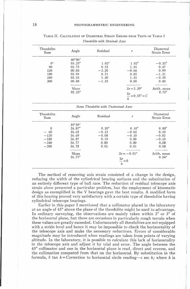
An examination of Table II will show the calculation of the strain error fromthe tests described in Table I. The average strain error which is considered permissible has been set at 0.12". With strained axes, the theodolite in questionshowed an average strain error of 0.75", while the same instrument after thestrain was removed showed this error reduced to 0.04".
It might be noted that the above test, besides strain, reveals many othertroubles-should they exist-and for that reason is exceedingly valuable forthe checking of all precision theodolites both before and after field use.

USE OF COLLIMATORS FOR TESTING AND ADJUSTING INSTRUMENTS 17
TABLE 1. TESTS FOR AXIS STRAIN IN THEODOLITE WITH AND WITHOUT
STRAINED AXES
Sequence With Strained Axes With Strain RemovedTheod. CircleBase of Setting Collima- Collima- Collima- Collima-Readings tor A tor B tor A tor B
0 [~. 0°00'00.0" 60°00'02.7" 0°00'00.0" 59°59'56.6"1 03.6 57.3
120 04.7 57.6180 01.5 55.4
12 240 03.4 56.7300 03.6 57.6
Mean 03 .25" 56.87"
- 60 !0
02.1 56.42 60 03.3 56.5
120 03.7 57.6180 01.7 55.4
11 240 01.6 56.3300 04.1 57.7
Mean 02.75" 56.65"
-120 !0
57.5 56.03 60 00.8 56.8
120 00.3 58.0180 00.0 55.6
10 240 59.4 56.1300 02.2 57.6
MeanOO.03" 56.69"
-180 ( 0 01.6 56.54 J 60 02.6 57.2
120 03.8 57.51180 02.7 55.6
9 [240 02.4 56.8300 04.6 57.6
Mean 02 .94" 56.87"
-240 !0
01.9 56.15 60 02.9 57.1
120 04.4 57.4180 03.2 55.8
8 240 03.8 56.6300 05.0 57.6
Mean 03 .53" 56.77"
-300 !0
01.4 56.26 60 00.7 57.1
120 02.9 57.7180 59.0 55.8
7 240 00.7 56.5300 00.6 57.4
Mean 00.88" 56.78"
18 PHOTOGRAMMETRIC ENGINEERING
TABLE II. CALCULATION OF DIAMETRAL STRAIN ERRORS FROM TESTS OF TABLE I
Theodolite with Strained Axes
TheodoliteBase
0°60
120180240300
Angle ResidualDiametral
r Strain Error
60°00'03.25" 1.02" 1.02" -0.55"02.75 0.52 1.54 0.4700.03 -2.20 -0.66 0.9902.94 0.71 0.05 -1.2103.53 1.30 1.35 -0.5000.88 -1.35 0.00 0.80
Mean ::!:r=3.30" Arith. mean02.23"
~=0.55"=C0.75"
6
Same Theodolite with Unstrained Axes
TheodoliteAngle Residual
DiametralBase r Strain Error
59°59'0 56.87" 0.10" 0.10" 0.00"
60 56.65 -0.12 -0.02 0.10-120 56.69 -0.08 -0.10 -0.02-180 56.87 0.10 0.00 -0.10-240 56.77 0.00 0.00 0.00-300 56.78 0.01 0.01 0.00
Mean ::!:r= -0.01" Arith. mean56.77"
~=O0.04"
6
The method of removing axis strain consisted of a change in the design,reducing the width of the cylindrical bearing surfaces and the substitution ofan entirely different type of ball race. The reduction of residual telescope axisstrain alone presented a particular problem, but the employment of kinematicdesign as exemplified in the Y bearings gave the best results. A modified formof this bearing proved very satisfactory with a certain type of theodolite havingcylindrical telescope bearings.
Earlier in this paper I mentioned that a collimator placed in the laboratoryat an angle of 45° above the plane of the theodolite might be used to advantage.In ordinary surveying, the observations are mainly taken within 2° or 3° ofthe horizontal plane, but there are occasions in particularly rough terrain whenthese values are greatly exceeded. Unfortunately all theodolites are not equippedwith a stride level and hence it may be impossible to check the horizontality ofthe telescope axis and make the necessary reductions. Errors of considerablemagnitude may be introduced when readings are taken from points of varyingaltitude. In the laboratory, it is possible to calculate this lack of horizontalityin the telescope axis and adjust it by trial and error. The angle between the45° collimator and one in the horizontal plane is read, direct and reverse, andthe collimation computed from that on the horizontal. By substitution in theformula, b tan h = Correction to horizontal circle reading-c sec h; where h is
USE OF COLLIMATORS FOR TESTING AND ADJUSTING INSTRUMENTS 19
45°; the correction to the horizontal circle reading is the difference betweeneither:reading on the 4S degree collimator and the mean of the direct and reverse readings; and c is the collimation on the horizontal collimator; the valuefor b will be the lack of horizontality in seconds.
It would be impossible to describe the many uses which are being made ofthe collimator in the laboratory for the adjusting and testing of precision instruments of which optics are an integral part. In the test which I have mentioned, we were confronted with an unknown which field tests failed to solve.Thanks to the collimator, we were enabled to determine definitely the sourceof the trouble, and with that information take the necessary steps to remove it.That our conclusions were accepted by the instrument makers themselves issufficient proof that our diagnosis was correct.
I would like here to pay tribute to J. L. Rannie, who originated and supervised these tests, to W. M. Dennis who acted as chief diagnostician and suggested the cure, and to R. H. Field who was frequently called into consultation.
A detailed description of the various tests carried out may be secured fromthe Dominion Geodesist, Geodetic Service of Canada, Ottawa.
RYKER STEREOSCOPESare
STANDARD EQUIPMENT IN MANY FEDERAL, STATE AND PRIVATEMAPPING PLANTS
D-lO Direct-vision Portable StereoscopesM-7 "HANDY" Mirror StereoscopesM-6 "WIDERANGE" Mirror StereoscopesSERIES M-9 "FIELDTYPE" Portable Mirror StereoscopesSp-l Stereoscopic Spectacles
TRIPLEX BASE and other ACCESSORIES.
HARRISON C. RYKER, INC. 1924 FRANKLIN STREETOAKLAND, CALIFORNIA, U.S.A.