Embed Size (px)
Citation preview
TABLE OF CONTENTS
Executive Summary . . . . . . . . . . . . . 1
Introduction . . . . . . . . . . . . . 2
Cathodic Protection Systems . . . . . . . . . . . . . 3-4
The Use of SPDs in
Flange Breakdown
Applications . . . . . . . . . . . . . 5
Process Transmitters . . . . . . . . . . . . . 5-6
Shared System ROW
Inductive Coupling Issues . . . . . . . . . . . . . 6-7
Conclusion . . . . . . . . . . . . . 8
References . . . . . . . . . . . . . 8
PHOENIX CONTACT • P.O. BOX 4100 • HARRISBURG, PA 17111-0100 1Phone: 800-888-7388 • 717-944-1300 • Technical Service: 800-322-3225 • Fax: 717-944-1625E-mail: [email protected] • Website: www.phoenixcontact.com
The Use of Surge Protective Devices in Mitigating the Effects of Lightning on the Natural Gas Pipeline Infrastructure
James Schroeder P.E., Schroeder Consulting ServicesFred Czubba, Phoenix Contact USA
© 2012 PHOENIX CONTACT
AUGUST 2012
Executive Summary
This paper will review the use and implementation
of surge protective devices (SPDs) in mitigating and
controlling the effects of conducted electromagnetic
interference (EMI) due to lightning strikes on the
natural gas pipeline infrastructure . The paper will
focus on the proper use of SPDs for the following
application areas:
• Cathodic protection systems
• Process transmitters
• Inductive coupling issues associated with lightning
strikes to electrical transmission equipment and the
resultant radiated and conducted damage to pipelines
located in the same right-of-way space
PHOENIX CONTACT • P.O. BOX 4100 • HARRISBURG, PA 17111-0100 2Phone: 800-888-7388 • 717-944-1300 • Technical Service: 800-322-3225 • Fax: 717-944-1625E-mail: [email protected] • Website: www.phoenixcontact.com
© 2012 PHOENIX CONTACT
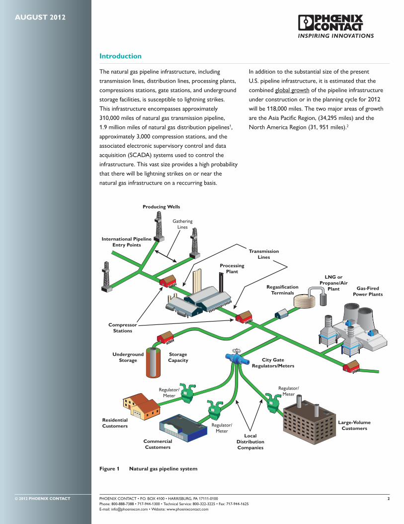
Introduction
The natural gas pipeline infrastructure, including
transmission lines, distribution lines, processing plants,
compressions stations, gate stations, and underground
storage facilities, is susceptible to lightning strikes.
This infrastructure encompasses approximately
310,000 miles of natural gas transmission pipeline,
1.9 million miles of natural gas distribution pipelines1,
approximately 3,000 compression stations, and the
associated electronic supervisory control and data
acquisition (SCADA) systems used to control the
infrastructure. This vast size provides a high probability
that there will be lightning strikes on or near the
natural gas infrastructure on a reccurring basis.
In addition to the substantial size of the present
U.S. pipeline infrastructure, it is estimated that the
combined global growth of the pipeline infrastructure
under construction or in the planning cycle for 2012
will be 118,000 miles. The two major areas of growth
are the Asia Pacific Region, (34,295 miles) and the
North America Region (31, 951 miles).2
AUGUST 2012
Large-VolumeCustomers
Regulator/Meter
Regulator/Meter
GatheringLines
Producing Wells
International PipelineEntry Points
Regulator/Meter
City GateRegulators/Meters
RegasificationTerminals
LNG orPropane/Air
Plant Gas-FiredPower Plants
CommercialCustomers
LocalDistributionCompanies
ResidentialCustomers
UndergroundStorage
CompressorStations
530
ProcessingPlant
TransmissionLines
StorageCapacity
Figure 1 Natural gas pipeline system

PHOENIX CONTACT • P.O. BOX 4100 • HARRISBURG, PA 17111-0100 3Phone: 800-888-7388 • 717-944-1300 • Technical Service: 800-322-3225 • Fax: 717-944-1625E-mail: [email protected] • Website: www.phoenixcontact.com
© 2012 PHOENIX CONTACT
Cathodic Protection Systems
The transmission lines and distribution lines
associated with the natural gas pipeline
infrastructure are made of steel and are
subject to corrosion. The two main methods
used to lessen and mitigate the effects
of corrosion are specialty coatings and
cathodic protection .3
The available types and application methods
of specialty coatings is beyond the scope of
this paper . Suffice to say that all transmission
lines are coated with long-term (10 years or
more) coating materials to inhibit the effects
of corrosion .
There are two types of cathodic protection systems
in use today for the natural gas pipeline infrastructure:
the galvanic protection (sacrificial) system and the
impressed current cathodic protection system (ICCP) .
Both of these systems require four components
to work:
1. An anode: made of copper or magnesium for
sacrificial systems, and silicon-cast iron, mixed
metal oxide, graphite, platinum or titanium-coated
alloys for ICCP systems
2. A cathode: the protected pipeline
3. An electrolyte: for underground pipeline, this
would be the earth
4. A connecting wire: to complete the circuit .
The galvanic system depends on the resistance of
the electrolyte (the earth) to establish the amount of
current flow between the cathode (pipeline) and the
anode (magnesium or copper rods placed in relatively
close proximity of the pipeline) . The anode rods are
sacrificial and need to be replaced on a periodic basis.
Changes in the earth’s resistance (due to soil type and
moisture content variations) will result in changes in
current flow between the anode and cathode. This
variability of current flow as a function of soil resistance
is the main uncontrolled variable of the galvanic system.
The galvanic system is primarily used in the distribution
segment of the pipeline infrastructure . This is due
to smaller pipe diameter, shorter run lengths, lower
current requirements, and the presence of foreign
metallic structures . A typical protection span for a
galvanic system is six to ten miles .
The ICCP system adds an external DC power supply to
stabilize and increase the required current flow of the
system (Figure 3).
The DC power supply used in the ICCP system
provides a higher, stabilized and adjustable current flow
for the system . This allows a longer protection span for
the ICCP system . ICCP systems are primarily used for
the transmission segment of the pipeline infrastructure .
ICCP systems typically span 30 to 40 miles. The
CATHODIC PROTECTION SYSTEMS continued ��
AUGUST 2012
e–
Copper
Copper
Tube
Active Metal(Anode)
Protected Metal(Cathode)
Figure 2 – Galvanic (sacrificial) protection schematic
Ground Surface
ProtectedPipeline
(Cathode)
Protective AnodeCurrent
Wire
Wire
Direct Current Source
Figure 3 Impressed Current System

PHOENIX CONTACT • P.O. BOX 4100 • HARRISBURG, PA 17111-0100 4Phone: 800-888-7388 • 717-944-1300 • Technical Service: 800-322-3225 • Fax: 717-944-1625E-mail: [email protected] • Website: www.phoenixcontact.com
© 2012 PHOENIX CONTACT
until the pipeline surfaces at a compression station,
transmission station or gate station. At that point,
the voltage wave meets a flange isolation interface .
Here, due to voltage differences between the isolated
section and the grounded section on the other side
of the isolation flange, the air immediately above the
flange could be ionized or the voltage differential
could be sufficient to puncture the dielectric of the
flange interface . Either result would lead to arcing and
potential igniting of any natural gas in the area . Surge
protective devices (SPDs) can prevent such events
from happening by limiting the voltage across the flange
interface to an acceptable level.
anodes of the ICCP system may be silicon-cast iron
(most economical), mixed metal oxide, graphite,
platinum or titanium-coated alloys .4 The main concern
of the impressed current system is that too high of
an impressed current can damage the pipe coating
or drive current to other structures not intended to
receive current .
Use of either of these systems as a corrosion resistance
measure requires that the supply pipes being protected
are electrically isolated from the system’s ground .
Therefore, when underground supply pipes surface at
compression stations, measurement and regulation
stations, gate stations, etc., an insulating flange
insert separates the electrically isolated pipe
(transmission or distribution lines) from the
electrically grounded pipe of the station .
Figure 4 shows a cross section of a typical flange
insert with sealing element .
The typical flange insert used to separate station
pipe from isolated CP pipe is a 1/8-inch-thick phenolic
retainer containing a precision tapered groove to
accommodate the controlled compression of a sealing
element .5 The phenolic retainer has a dielectric
breakdown voltage of 500 volts per mil. Therefore,
the dielectric breakdown voltage from isolated pipe to
system pipe through the retainer wall would be 500
v/m*125mil = 62,500 volts.
By comparison, the dielectric breakdown voltage of
air under standard conditions (20°C and 20% R. H.)
is generally accepted to be 3 x 10⁶ volts/meter or 76
volts/mil. Therefore, the dielectric breakdown voltage
of the air immediately above the flange between
the isolated pipe and the system pipe would be
76v/m*125m = 9,500 volts.
During direct or nearby lightning strikes in the vicinity
of the supply pipeline, strong earth currents and voltage
gradients are developed in the adjacent soil. These
gradients result in voltage potential differences of
several thousand volts across the supply pipeline . This
high-voltage gradient wave travels along the pipeline
AUGUST 2012
CATHODIC PROTECTION SYSTEMS continued ��
Figure 4 Typical flange insert

PHOENIX CONTACT • P.O. BOX 4100 • HARRISBURG, PA 17111-0100 5Phone: 800-888-7388 • 717-944-1300 • Technical Service: 800-322-3225 • Fax: 717-944-1625E-mail: [email protected] • Website: www.phoenixcontact.com
© 2012 PHOENIX CONTACT
AUGUST 2012
The Use of SPDs in Flange Breakdown Applications
SPDs are electronic devices
that switch to a low impedance
mode at a predetermined
voltage level . They enter a low-
voltage, high-current mode
after reaching their triggering
voltage . In the situation
described above, the SPD
will act to limit the voltage
gradient that has developed
across the isolated flange to a value below either the
dielectric breakdown of air or the dielectric breakdown
of the flange insert .
A controlled triggered spark gap (Figure 5) is one of the
SPD configurations that can be used for this application.
The triggering voltage for the spark gap is typically set
at approximately 1000 V, well below the breakdown
voltage of air or the breakdown voltage of the flange
dielectric . When the transient voltage gradient
amplitude reaches approximately 1000 V, the spark
gap begins to conduct. This equalizes the voltages on
both sides of the flange and maintains the integrity of
the flange interface and the surrounding air dielectric .
Figure 6 shows an example of a triggered spark gap SPD
protecting an isolated pipeline flange .
Process Transmitters
Process transmitters are a part of the electronic
supervisory control and data acquisition (SCADA)
system used to control the pipeline infrastructure .
Process transmitters are found in measurement
equipment such as flow meters and are usually located
remotely from control stations .6 SPDs are used to
protect the electrical integrity of process transmitters
in one of two ways .
A process transmitter used to measure data as part of
the flow meter process center can be locally grounded
at the site . This localized grounding of the transmitter
will result in the formation of ground loops if a high-
voltage transient (lightning strike) occurs at or near the
locally grounded control station (Figure 7).
A lightning strike at or near the control center will
increase the ground voltage potential at the control
center relative to the localized ground voltage at
the process transmitter by several thousand volts,
depending upon the amplitude and duration of the
lightning strike. This imbalance in ground potential
between the control center and the process center will
cause a transient surge current in the earth (ground
current) to flow, creating what is known as a ground
loop . This ground current will flow into the process
transmitter and cause transmitter failure . To avoid
transmitter failure, insert an SPD such as the one
shown in Figure 8 into the ground leg of the process
transmitter . These SPDs are known generically as TP-48
class SPDs . The transmitter is usually threaded into the
metal casing of the flow meter .
PROCESS TRANSMITTERS continued ��
Figure 5 Triggered spark gap
Figure 6 Isolated flange spark gap protection scheme
TriggerPulse
To ChargingVoltage Suppy
Electrode1
Electrode2
+
Flange
Ground Loop Current
Pipeline
Pipeline
Lightningstrike
GateStation
Localized groundreference. Risesabove “0” voltsdue to lightningstrike. Di�erence between localized
and remote references sets upground loop current. Magnitudeof current is function of lightningstrike energy content.
Remote “0” VoltReference.
M & RStation
Figure 7 Ground loop formation between control station and process transmitter

PHOENIX CONTACT • P.O. BOX 4100 • HARRISBURG, PA 17111-0100 6Phone: 800-888-7388 • 717-944-1300 • Technical Service: 800-322-3225 • Fax: 717-944-1625E-mail: [email protected] • Website: www.phoenixcontact.com
© 2012 PHOENIX CONTACT
AUGUST 2012
Shared System ROW Inductive Coupling Issues
Distribution natural gas pipelines often use the same
right-of-way (ROW) as other utilities, usually electrical
power distribution utilities. This minimizes the amount
of land required for utilities in a given locality . The
proximity of different utilities in the same ROW can
cause unexpected and serious problems for natural
gas pipelines when lightning strikes the electrical
distribution utility (Figure 9).
As illustrated in Figure 9, buried pipelines in the vicinity
of electrical distribution systems are susceptible to
inductively coupled transients and parasitic ground
currents as a result of lightning strikes to the nearby
electrical transmission lines . The amount of damage
sustained by the pipeline due to the lightning strike
is a function of the magnitude and duration of the
strike’s energy level at the point of contact with
the electrical distribution system. While
calculating the resultant energy coupling
into the gas pipeline is complex
There are reasons not to ground the process
transmitter used to measure data as part of the
flow meter process center . One reason is to provide
mechanical isolation from the piping, which can be the
actual source of the surge fault current traveling along
the pipe . Another is the prevention of the ground
loop scenario caused by multiple ground references.
Whatever the reason, implementing a TP-48 SPD in
the reference leg of the transmitter can protect the
electrical integrity of the floating transmitter . This
will serve to limit the surge voltage between the
transmitter and system ground to a manageable level
and preserve the functionality of the transmitter .
PROCESS TRANSMITTERS continued ��
SHARED SYSTEM ROW continued ��
Figure 9 Shared System ROW Inductive Coupling Issues
Figure 8 TP 48 Surge Protective Device
IsolatingFlange
IsolatingFlange
Ground
Pipe
Earth Fault/Short Circuit
CurrentElectromagnetic
Interference
LightningStrikes
PHOENIX CONTACT • P.O. BOX 4100 • HARRISBURG, PA 17111-0100 7Phone: 800-888-7388 • 717-944-1300 • Technical Service: 800-322-3225 • Fax: 717-944-1625E-mail: [email protected] • Website: www.phoenixcontact.com
© 2012 PHOENIX CONTACT
AUGUST 2012
and beyond the scope of this paper, it can be said
that the energy level that is coupled into the pipeline
infrastructure will vary inversely with the distance from
the strike’s contact point .7 Therefore, maximizing the
distance between the electrical utility structure and the
pipeline within the constraints of the ROW dimensions
will serve to minimize the amount of energy coupled
into the pipeline .
Damage from past incidents due to the coupling
mechanisms described above has included damaged
electrical conduit and cabling, destroyed flange guards,
damaged grounding cables and pipeline exterior,
damaged turbine meters and pressure controllers.8 The
following SPD measures can mitigate future damage to
above-ground or buried pipeline due to lightning strikes
under similar conditions:
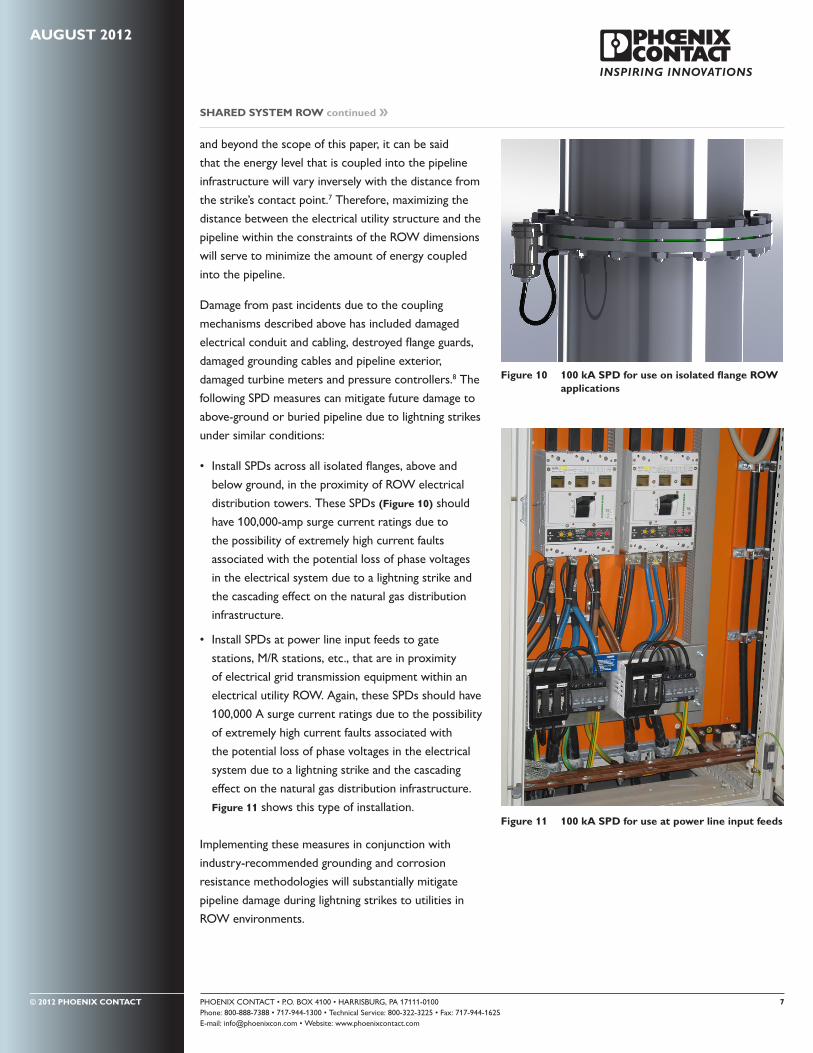
• Install SPDs across all isolated flanges, above and
below ground, in the proximity of ROW electrical
distribution towers. These SPDs (Figure 10) should
have 100,000-amp surge current ratings due to
the possibility of extremely high current faults
associated with the potential loss of phase voltages
in the electrical system due to a lightning strike and
the cascading effect on the natural gas distribution
infrastructure .
• Install SPDs at power line input feeds to gate
stations, M/R stations, etc., that are in proximity
of electrical grid transmission equipment within an
electrical utility ROW. Again, these SPDs should have
100,000 A surge current ratings due to the possibility
of extremely high current faults associated with
the potential loss of phase voltages in the electrical
system due to a lightning strike and the cascading
effect on the natural gas distribution infrastructure.
Figure 11 shows this type of installation .
Implementing these measures in conjunction with
industry-recommended grounding and corrosion
resistance methodologies will substantially mitigate
pipeline damage during lightning strikes to utilities in
ROW environments .
SHARED SYSTEM ROW continued ��
Figure 10 100 kA SPD for use on isolated flange ROW applications
Figure 11 100 kA SPD for use at power line input feeds

PHOENIX CONTACT • P.O. BOX 4100 • HARRISBURG, PA 17111-0100 8Phone: 800-888-7388 • 717-944-1300 • Technical Service: 800-322-3225 • Fax: 717-944-1625E-mail: [email protected] • Website: www.phoenixcontact.com
© 2012 PHOENIX CONTACT
References
1. Pipeline and Gas Journal; May 2012; Pg. 56 –
US Department of Transportation’s Office of
Pipeline Safety.
2. Pipeline & Gas Journal; January 2012; “2012
Worldwide Pipeline Construction Report,” Pg. 26.
3. 71st Annual Appalachian Gas Measurement Short
Course 2011, “Corrosion Control Considerations for
M&R Stations,” Michael J. Placzek, P.E., Duke Energy
Gas Transmission.
4. “Cathodic Protection” – a knol by Adam Junid: http://
knol.google.com/k/cathodic-protection
5. Pipeline Seal & Insulator, Inc., Linebacker Flange
Isolation Kits Catalog, Pg. 7.
6. Emerson Process Management, Model 1700 and
2700 Field and Integral Mount Transmitter.
7. The Lightning Discharge, Martin A. Uman, 2001.
Chapter 7 , Pg. 111.
8. 71st Annual Appalachian Gas Measurement Short
Course 2011, “Grounding Techniques at Plants and
Gate Stations,” Pg. 314, Donald R. Long, ISTA, Inc., and
Matthew G. Esmacher, P.E., Washington Gas.
AUGUST 2012
Conclusion
This paper has discussed the implementation and usage
of SPDs for the protection of the transmission and
distribution of natural gas pipeline infrastructure against
damage created by lightning strikes. Specifically the
paper has focused on the following areas of concern
related to the pipeline infrastructure:
• Cathodic protection systems
• Process transmitters
• Inductive coupling issues associated with lightning
strikes to electrical transmission equipment and the
resultant radiated and conducted damage to pipelines
located in the same right-of-way space .
By understanding the principles discussed here and
implementing the recommendations, it is possible to
mitigate future potential pipeline damage related to
lightning strikes. Indeed, an investment in strategically
placed SPDs in critical use areas could return a
significant savings in future cost of unmitigated damages .
ABOUT PHOENIX CONTACT
Phoenix Contact develops and manufactures industrial electrical
and electronic technology products that power, protect,
connect and automate systems and equipment for a wide range
of industries. Phoenix Contact GmbH & Co. KG, Blomberg,
Germany, operates 50 international subsidiaries, including
Phoenix Contact USA in Middletown, Pa.
For more information about Phoenix Contact or its products,
visit www.phoenixcontact.com, call technical service at
800-322-3225, or e-mail [email protected].