Embed Size (px)
Citation preview

K. A. Fretz, E. Y. Adams, and K. W. Kirby
Johns Hopkins APL Technical Digest, Volume 33, Number 3 (2016), www.jhuapl.edu/techdigest202
The Van Allen Probes Observatories: Overview and Operation to Date
Kristin A. Fretz, Elena Y. Adams, and Karen W. Kirby
ABSTRACTThe Van Allen Probes Mission successfully launched on the morning of 30 August 2012 from Ken-nedy Space Center. As part of NASA’s Living With a Star Program, the Probes mission uses two iden-tically instrumented spinning observatories to address how populations of high energy charged particles are created, vary, and evolve within Earth’s magnetically trapped radiation belts. The observatories operate in slightly different elliptical orbits around Earth, lapping each other four times per year, to provide a full sampling of the radiation belts as well as simultaneous measure-ments over a range of observatory separation distances. This article discusses the key character-istics of the spacecraft and its subsystems and payload, as well as the observatory environments that were drivers for the mission. In addition, the article describes mission operations and the telemetry trending approach used to evaluate spacecraft health.
(EMFISIS), the Relativistic Proton Spectrometer (RPS), the Electric Field and Waves Suite (EFW), and the RBSP Ion Composition Experiment (RBSPICE).
The mission was developed for a baseline life of 2 years and 74 days, which includes a 60-day commissioning period after launch, a 2-year science mission, and 14 days at the end of the mission for disposal. The 2-year science mission lifetime was required to provide sufficient local time, altitude, and event coverage to improve the under-standing and determine the relative significance of the various mechanisms that operate within the radiation belts and their individual and collective effects (see the article by Adams and Fretz in this issue).
The twin observatories successfully launched on an Atlas V-401 launch vehicle from Kennedy Space Center on 30 August 2012. The launch vehicle released each observatory separately and was responsible for orient-
INTRODUCTION/MISSION OVERVIEWThe Van Allen Probes mission, previously known
as Radiation Belt Storm Probes (RBSP), was built and is operated by the Johns Hopkins University Applied Physics Laboratory (APL). By flying two function-ally equivalent observatories through Earth’s radiation belts, the Van Allen Probes mission studies the varia-tions in solar activity and how these variations affect Earth’s environment. The data obtained during the mission improve the overall knowledge of the radiation belts and how they respond to solar storms and events, allowing scientists to improve and develop new models of this important aspect of Earth’s environment. The observatory instruments measure high- and low-energy electrons and protons, ion composition, and electric and magnetic fields using the Energetic Particle, Composi-tion, and Thermal Plasma Suite (ECT), the Electric and Magnetic Field Instrument Suite and Integrated Science

The Van Allen Probes Observatories: Overview and Operation to Date
Johns Hopkins APL Technical Digest, Volume 33, Number 3 (2016), www.jhuapl.edu/techdigest 203
ing each observatory with solar arrays pointed to the Sun. The nominal injection orbits have apogee altitudes between 30,050 and 31,250 km, peri-gee altitudes between 500 and 675 km, and inclinations of 10°. The spacecraft spin con-tinuously at a nominal speed of 5.5 rpm, with the spin axis pointed off the Sun 15° to 27°.1 To date, the Van Allen Probes mission has achieved all of its Level-1 science goals and suc-cessfully completed its prime mission. A 2-year extension for the Van Allen Probes began on 1 November 2015. The observatories are expected to operate beyond the 2-year extension, as they carry con-sumables to continue operation until early 2019.
The mission was classified as Risk Category C (using a mostly single-string architecture). Key mission and observatory design drivers included the following:2
• Missionrequirements
J Maximize the time in the radiation belts using an orbit with an apogee of 30,500 km and peri-gee of 600 km
J Provide identically instrumented twin observa-tories
J Launch both observatories on a single launch vehicle
J Design for a mission life of 2.25 years with a goal of 5 years
J Provide near-continuous transmission of space weather information as described in the article by Zanetti et al. in this issue
• Observatoryrequirements
J Operate through the radiation beltsJ Allow for payload data sharing in real time to
trigger burst observationsJ Provide accurate time knowledge to allow for
correlation of payload measurementsJ Continue operating and collecting data through
the worst-case solar storm environmentJ Provide near-Sun-point, spin-stabilized attitude
control for instrument fields of viewJ Support average payload power of 149 W and
operate through eclipses of up to 114 minJ Provide an average daily downlink volume of at
least 5.9 Gbits of recorded plus real-time data per day
J Accommodate a payload mass of 130 kgJ Deploy booms for fluxgate and search coil mag-
netometersJ Deploy booms for axial and wire radial booms
for electric field measurementsFigure 1 shows the observatory and depicts the pay-
load accommodation.The remainder of this article describes the environ-
ments the mission has to survive and the unique space-craft design that resulted from needing to operate in those environments, payload accommodation, and mis-sion operations to date.
OBSERVATORY ENVIRONMENTSRadiation Environment
One of the most unique challenges for the observa-tory design was the mitigation of the radiation concerns. The observatory and components are required to oper-ate continuously through the heart of the radiation belts twice every ~9-h orbit for the duration of the mission. The belts are composed of trapped energetic protons and electrons, which affect the observatories by contributing to the total ionizing dose, single-event effects, surface charging, and deep dielectric charge/discharge of elec-tronics. The energetic (up to hundreds of megaelectron volts) protons provide the majority of the penetrating dose and all of the displacement damage. The outer belt electrons bombard the observatory during the long exposures near apogee and are the second major con-tributor to the total ionizing dose.
Analysis was performed to determine the shielding needed to mitigate the total dose effects. The results were used to set the parts requirements. The parts had to be rated to at least 34 krads [23 krads for the Integrated
EFWspin plane wire boom (4x)
ECT hopeECT MagEIS(low and medium 75) RBSPICE
ECT REPT
EMFISISmagnetometerboom
ECT MagEIS(high and medium 35)
RPS
EMFISIS search coil boom
EFW axial boom(fwd and aft)
Figure 1. Observatory configuration showing instrument fields of view.

K. A. Fretz, E. Y. Adams, and K. W. Kirby
Johns Hopkins APL Technical Digest, Volume 33, Number 3 (2016), www.jhuapl.edu/techdigest204
Electronics Module (IEM)] without parametric or func-tional failure. This value was based on the baseline mis-sion lifetime, with a radiation design margin factor of 2 and a nominal shield depth of 350 mils (500 mils for the IEM) of aluminum. After the observatory mechanical configuration was defined, the maximum total dose of 15.4 krads (radiation design margin = 2) was determined for individual electronic boxes and locations due to sub-stantial shielding for their neighboring boxes.2
The solar panels, instrument optics, and exposed detectors had to withstand displacement damage associ-ated with the trapped proton fluence. The observatories were designed to the modeled 10 MeV equivalent proton fluence. For the box wall thicknesses of 350–500 mils, the fluences were in the range of 5 × 10¹⁰ to 8 × 10¹⁰ p/cm2. The solar cells were designed to withstand an equiva-lent 1 MeV electron fluence of 1.35 × 10¹⁵ e/cm2 behind 20-mil coverglass thicknesses.2
The estimated deep-space cosmic ray integral linear energy transfer spectra for the Van Allen Probes orbit was used to estimate the upset rates of single-event effects. The “worst week” environment curve together with the experimentally determined upset cross section was used in upset rate calculations. Parts susceptible to single-event latch-up with linear energy transfer thresh-old of less than 80 MeV-cm2/mg were not used.2 Failure modes and effects analysis demonstrated that single-event upsets in parts would not cause mission-critical failures. Single-event upsets in parts of noncritical systems were not allowed to compromise flight system health or mission performance.
Critical digital parts (i.e., programmable devices, memories, and microprocessors) were evaluated for sus-ceptibility to single-event upset effects, such as single- and double-bit errors, functional interrupt, and stuck bits. Critical linear and mixed-signal devices were eval-uated for proton-induced single-event transients. Power devices were analyzed for single-event burnout and gate rupture. The peak proton flux expected in the Van Allen Probes orbit was calculated to be 1.0 × 10⁶ protons/cm2-s with energy greater than 10 MeV; the peak elec-tron flux was calculated to be 3.7 × 10⁷ electrons/cm2-s with energy greater than 1 MeV (Ref. 2). These peak fluxes produce noise, affecting dynamic integrated cir-cuit performance, guidance and control sensors, and sci-ence instrument resolution. Hardware was designed to operate through these levels.
Electromagnetic EnvironmentThe Van Allen Probes science investigations rely on
accurate understanding of the ambient environment in which the various measurements are being made. This drives the need for both magnetic and electric (differ-ential charging) cleanliness of the observatories. Each observatory was required to have a residual magnetic
field (as measured at the magnetometer locations) of >5 nT, with dynamic variations of this residual field of >0.1 nT. Similarly, the observatory-generated electric field as measured at the tip of the EFW axial booms was required to be >4 mV/m, even in the worst-case charg-ing environments. However, internal charging was most critical to the observatory design since electrical dis-charges due to internal charging of dielectrics or floating conductors could actually damage electrical hardware and cause mission failure. Mitigations for internal charg-ing, surface charging, and electromagnetic cleanliness are discussed below, and more details about the rigorous test program can be found in Kirby et al.3
Internal ChargingInternal charging and deep dielectric discharge are
both caused by high-energy electrons and ions pen-etrating the observatory structure and coming to rest in the spacecraft. In particular, the electron flux in the energy range of 0.1–10 MeV is large enough to accumu-late substantial charge in dielectric materials and float-ing conductors. The particles ultimately cause internal surfaces to charge until they exceed the breakdown or gap voltage, at which point it discharges to the local ground. The discharge can result in damage to elec-tronic circuits or can cause upsets or noise in space-craft subsystems or instruments. To prevent discharges, the floating conductors and large dielectric surfaces were not allowed anywhere on the observatories unless shielded with enough metal to prevent charging. In addition, harness and devices were designed to operate with a multitude of the discharges occurring, requiring special circuitry, additional shielding over some cables, and the use of large drain resistors to connect to ground in some circuits. All first circuit interfaces had to sur-vive the discharges, and pulse rejection circuits were required, typically located in a field-programmable gate array for digital devices.2
Surface ChargingLow- and medium-energy particle accumulation and
electron emission in sunlight causes differential charg-ing of the observatory surfaces. If sections of the obser-vatory are not electrically connected, large potential differences develop. These potential differences can lead to discharges or can contaminate the electric field and particle measurements. The observatories were designed so that all outer and inside surfaces are conductive and bonded together. Conductive adhesives and black paint were crucial to meeting the charging requirements.2
Magnetic CleanlinessMagnetic cleanliness of the observatories was ensured
by designing the layout of all circuits to minimize closed-current loops and allowing only balanced differential
The Van Allen Probes Observatories: Overview and Operation to Date
Johns Hopkins APL Technical Digest, Volume 33, Number 3 (2016), www.jhuapl.edu/techdigest 205
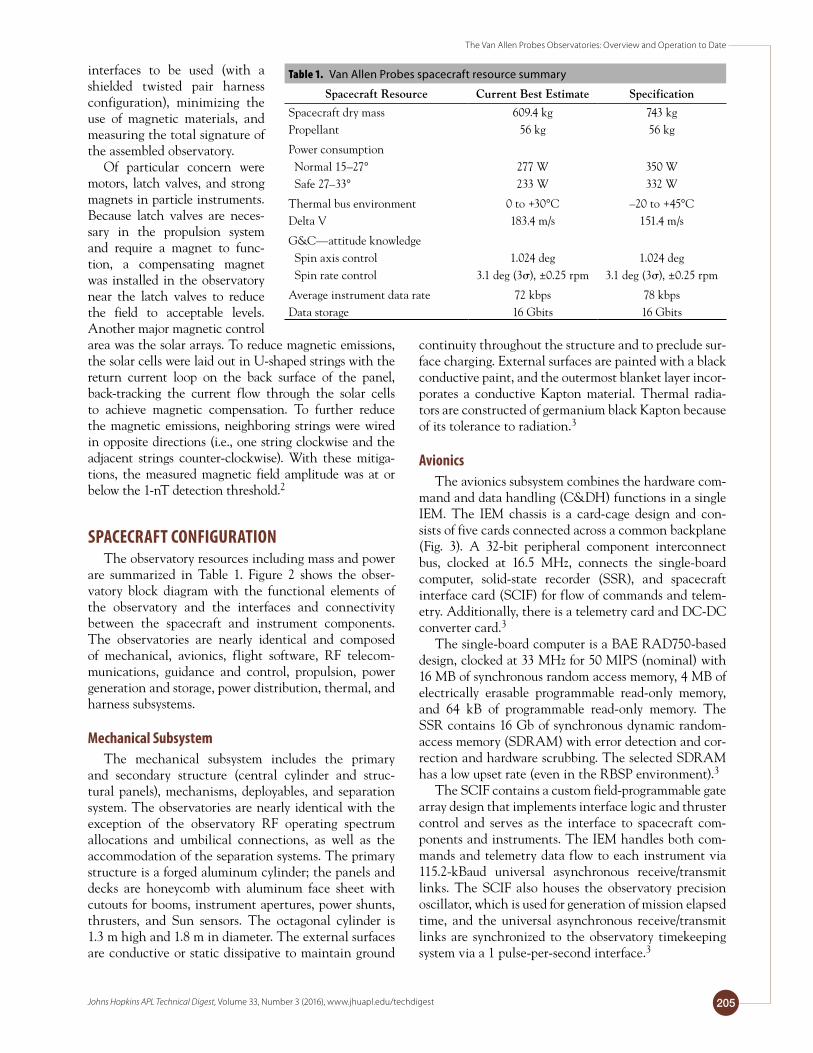
interfaces to be used (with a shielded twisted pair harness configuration), minimizing the use of magnetic materials, and measuring the total signature of the assembled observatory.
Of particular concern were motors, latch valves, and strong magnets in particle instruments. Because latch valves are neces-sary in the propulsion system and require a magnet to func-tion, a compensating magnet was installed in the observatory near the latch valves to reduce the field to acceptable levels. Another major magnetic control area was the solar arrays. To reduce magnetic emissions, the solar cells were laid out in U-shaped strings with the return current loop on the back surface of the panel, back-tracking the current flow through the solar cells to achieve magnetic compensation. To further reduce the magnetic emissions, neighboring strings were wired in opposite directions (i.e., one string clockwise and the adjacent strings counter-clockwise). With these mitiga-tions, the measured magnetic field amplitude was at or below the 1-nT detection threshold.2
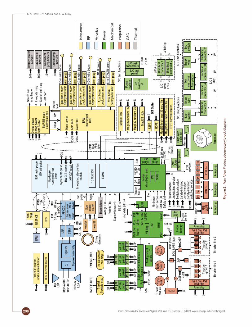
SPACECRAFT CONFIGURATIONThe observatory resources including mass and power
are summarized in Table 1. Figure 2 shows the obser-vatory block diagram with the functional elements of the observatory and the interfaces and connectivity between the spacecraft and instrument components. The observatories are nearly identical and composed of mechanical, avionics, flight software, RF telecom-munications, guidance and control, propulsion, power generation and storage, power distribution, thermal, and harness subsystems.
Mechanical SubsystemThe mechanical subsystem includes the primary
and secondary structure (central cylinder and struc-tural panels), mechanisms, deployables, and separation system. The observatories are nearly identical with the exception of the observatory RF operating spectrum allocations and umbilical connections, as well as the accommodation of the separation systems. The primary structure is a forged aluminum cylinder; the panels and decks are honeycomb with aluminum face sheet with cutouts for booms, instrument apertures, power shunts, thrusters, and Sun sensors. The octagonal cylinder is 1.3 m high and 1.8 m in diameter. The external surfaces are conductive or static dissipative to maintain ground
continuity throughout the structure and to preclude sur-face charging. External surfaces are painted with a black conductive paint, and the outermost blanket layer incor-porates a conductive Kapton material. Thermal radia-tors are constructed of germanium black Kapton because of its tolerance to radiation.3
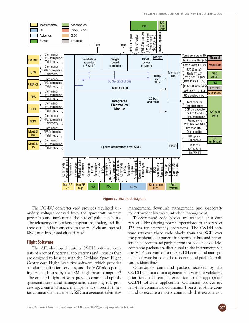
AvionicsThe avionics subsystem combines the hardware com-
mand and data handling (C&DH) functions in a single IEM. The IEM chassis is a card-cage design and con-sists of five cards connected across a common backplane (Fig. 3). A 32-bit peripheral component interconnect bus, clocked at 16.5 MHz, connects the single-board computer, solid-state recorder (SSR), and spacecraft interface card (SCIF) for flow of commands and telem-etry. Additionally, there is a telemetry card and DC-DC converter card.3
The single-board computer is a BAE RAD750-based design, clocked at 33 MHz for 50 MIPS (nominal) with 16 MB of synchronous random access memory, 4 MB of electrically erasable programmable read-only memory, and 64 kB of programmable read-only memory. The SSR contains 16 Gb of synchronous dynamic random-access memory (SDRAM) with error detection and cor-rection and hardware scrubbing. The selected SDRAM has a low upset rate (even in the RBSP environment).3
The SCIF contains a custom field-programmable gate array design that implements interface logic and thruster control and serves as the interface to spacecraft com-ponents and instruments. The IEM handles both com-mands and telemetry data flow to each instrument via 115.2-kBaud universal asynchronous receive/transmit links. The SCIF also houses the observatory precision oscillator, which is used for generation of mission elapsed time, and the universal asynchronous receive/transmit links are synchronized to the observatory timekeeping system via a 1 pulse-per-second interface.3
Table 1. Van Allen Probes spacecraft resource summary
SpacecraftResource CurrentBestEstimate Specification
Spacecraft dry mass 609.4 kg 743 kgPropellant 56 kg 56 kg
Power consumption Normal 15–27° Safe 27–33°
277 W233 W
350 W332 W
Thermal bus environment 0 to +30°C –20 to +45°CDelta V 183.4 m/s 151.4 m/s
G&C—attitude knowledge Spin axis control Spin rate control
1.024 deg3.1 deg (3), ±0.25 rpm
1.024 deg3.1 deg (3), ±0.25 rpm
Average instrument data rate 72 kbps 78 kbpsData storage 16 Gbits 16 Gbits
K. A. Fretz, E. Y. Adams, and K. W. Kirby
Johns Hopkins APL Technical Digest, Volume 33, Number 3 (2016), www.jhuapl.edu/techdigest206
Purg
esy
stem
Sep
switc
hes
x4
Mag
EIS
low
Mag
EIS
med
ium
35
Mag
EIS
med
ium
75
Mag
EIS
high
REPT
HOPE
RBSP
ICE
Arm
plug
RPS
S
U S S SU S
S
RBSP
ICE
oper
ate
and
surv
ival
hea
ter
RPS
surv
ival
hea
ter
ERM
Top
LGA
LNA He
ad A
Head
B
Ther
mis
tors
Dipl
exer
ass
embl
y
IEM
OP re
qPD
UOP
req
to P
DU
Tran
scei
ver
RF C
CD Mai
npo
wer
Off
puls
e
SUCM
DTL
M1
PPS/
spin
SSSS
BB Tlm
Sun
puls
ex2
Angl
eSu
nse
nsor
elec
tr.S
2 rin
gda
mpe
rs
Botto
mLG
A
EMFI
SIS
MEB
EMFI
SIS
MEB
RBSP
-A R
CPRB
SP-B
LCP
U U
EFW
inst
rum
ent
DPU
EMFI
SIS
mai
nel
ectr
onic
s bo
x
Digi
tal p
ower
Anao
g po
wer
FGM
hea
ter
Mai
n po
wer
Spin
BDU
Axia
l BDU
Sear
ch c
oil
mag
hea
ter
Flux
gate
mag
Sear
ch c
oil m
ag
Elec
tric
�eld
Test
por
t
IEM
mai
n po
wer
IEM
off-
puls
e
SCM
FGM
S
2xSS
2xSS
PDU
Syst
em o
ff-pu
lse
HW C
LT p
ower
HW C
LT re
set
U P
Hard
war
eco
mm
and
loss
timer
Inte
grat
ed e
lect
roni
csm
odul
e
EMXO
LVS
SEQs
PDU
S/C
Umb
func
tions
S/C
Umb
Fcns
S/C
A on
ly
LV fa
iring
IEM
S/C
test
func
tions
16 G
bit S
SR
Volta
ge T
lm
Switc
h TT
s
Sep
switc
hes
(4)
BB C
md
Hskp
dat
a (I&
T)
Mag
EIS
high
-med
35
surv
htr
Mag
EIS
low
-med
75
surv
htr
REPT
sur
viva
l hea
ter
Batte
ry h
eate
r A
and
B
S/C
surv
ival
heat
ers
Nonc
ritic
alpr
op h
eate
rs
Criti
cal p
rop
heat
ers
2xU
3xS S U
LRB
Pow
er
dist
ribut
ion
unit
Fuseplugs
S/C test connectors
S/C test panel
Armplugs
CMD
TLM
OP Req
CCD
Thrs
ter
�re
x2
SS
S
Pwr
Umb
pwr
Batt
sens
eSe
p sw
(4)
Safe
ty c
trl
Puls
ed s
ervi
ceUn
switc
hed
serv
ice
Switc
hed
serv
ice
Safe
ty-i
nhib
ited
puls
ed s
ervi
ceSa
fety
-inh
ibite
dsw
itche
d se
rvic
e
P U S SP SS
PSE I/F
Batt
Cell
byp
enCu
rrct
rler
BME
PSE
Pwr
Disc
on
CMD
& TL
MLB
SOC
VT R
eg
PDB
LV/P
T
4xSP
2xP
Arm
plu
gsAr
m p
lug
Arm
plu
g
P1P4
S1S4
P2P3
S2S3
P2P4
S2S4
PDB
T–PD
B T+
Arm
plu
g
Arm
plug
s
PDU
serv
ices
2x O
P re
q(X
CVR) OP
req
(HW
CLT)
S/C
test
pan
elPl
ugs
with
blee
d Rs
Harn
ess
Sep
switc
hBr
eak
wire
U
S S S S
S ECT
Suite
S
U U UP
S
S/C
Umb
func
tions
Armplug
x2
Bypa
ss
Sw �
re
Li-i
onba
ttery
shunts
S S
2xP
2xSP
Thru
ster
�re
2Th
rust
er �
re 1
CMD
TLM
1 PP
S/sp
in
Arm plugPri & Sec Cat
Bed Htrs
S S
Arm plug
Pri & Sec CatBed Htrs
Thru
ster
gr
oup
2Th
rust
er
grou
p 1
P1P3
S1S3
F
S
PTPC
N 2H 4
Tank
2N 2
H 4Ta
nk 3
N 2H 4
Tank
1PT
test
pw
r x4
2xSP
SAS
2xSP
2xSP 4x
SS
Umb
(dis
c)PD
U &
PSE
(con
)
L
L
L
SPSP
SPSP
SPSP
SPSP
SPSP
SPSP
PPPP
PPPP
PPPP
+Y
SApa
nel
PPPP
PPPP
PPPP
–Y S
Apa
nel
+X
SApa
nel
–X S
Apa
nel
Sola
r arr
ay ju
nctio
n bo
xFu
ll
Redu
ced
Anal
og s
hunt
pane
ls 1
–7
Tria
xial
�uxg
ate
mag
Tria
xial
sea
rch
coil
mag
PP
50-m
wire
boo
m
50-m
wire
boo
m
40-m
wire
boo
m
40-m
wire
boo
m
6-m
STA
CER
boom
6-m
STA
CER
boom Br
eak
wire
Sep
switc
h
Umbi
lical
conn
ecto
r 1
Umbi
lical
conn
ecto
r 2
Sep
sys
pyro
sAr
m p
lugs
Umbi
lical
conn
ecto
r 3A
Umbi
lical
conn
ecto
r 3B
Umbi
lical
conn
ecto
r 2Um
bilic
alco
nnec
tor 1
S/C
Bon
lyLV
LVLV
LVSt
ruct
ure
Dipl
exer
∑SS
PAAr
m p
lug
Arm
plu
g
Arm
plu
g
Arm
plu
g
Arm
plu
g
Arm
plu
g
Spin
pla
ne b
oom
depl
oym
ent u
nit
Spin
pla
ne b
oom
depl
oym
ent u
nit
Spin
pla
ne b
oom
depl
oym
ent u
nit
Spin
pla
ne b
oom
depl
oym
ent u
nit
Axia
l boo
mde
ploy
men
t uni
t
Axia
l boo
mde
ploy
men
t uni
t
Inst
rum
ents
RF
Avi
onic
s
Pow
er
Mec
hani
cal
Pro
pul
sion
G&
C
Ther
mal
Figu
re 2
. Va
n A
llen
Prob
es o
bser
vato
ry b
lock
dia
gram
.
The Van Allen Probes Observatories: Overview and Operation to Date
Johns Hopkins APL Technical Digest, Volume 33, Number 3 (2016), www.jhuapl.edu/techdigest 207
The DC-DC converter card provides regulated sec-ondary voltages derived from the spacecraft primary power bus and implements the box off-pulse capability. The telemetry card gathers temperature, analog, and dis-crete data and is connected to the SCIF via an internal I2C (inter-integrated circuit) bus.3
Flight SoftwareThe APL-developed custom C&DH software con-
sists of a set of functional applications and libraries that are designed to be used with the Goddard Space Flight Center core Flight Executive software, which provides standard application services, and the VxWorks operat-ing system, hosted by the IEM single-board computer.4 The onboard flight software provides command uplink, spacecraft command management, autonomy rule pro-cessing, command macro management, spacecraft time-tag command management, SSR management, telemetry
management, downlink management, and spacecraft-to-instrument hardware interface management.
Telecommand code blocks are received at a data rate of 2 kbps during normal operations, or at a rate of 125 bps for emergency operations. The C&DH soft-ware retrieves these code blocks from the SCIF over the peripheral component interconnect bus and recon-structs telecommand packets from the code blocks. Tele-command packets are distributed to the instruments via the SCIF hardware or to the C&DH command manage-ment software based on the telecommand packet’s appli-cation identifier.2
Observatory command packets received by the C&DH command management software are validated, prioritized, and sent for execution to the appropriate C&DH software application. Command sources are real-time commands, commands from a real-time com-mand to execute a macro, commands that execute as a
Test Test
IEM
uns
w p
wr
IEM
off-
puls
e
HWCL
T un
sw p
wr
HWCL
T sw
pw
r
S/C
POR
req
(rese
t pul
se)
HWCL
T sp
eedu
p
PDUS/C test conn
Com
man
ds1
PPS/
spin
pul
seTe
lelm
etry
MagEIS75
Sep
TT #
1Se
p TT
#2
Sep
TT #
3Se
p TT
#4
Sep.system
Com
man
ds1
PPS/
spin
pul
seTe
lelm
etry
MagEIShigh
Com
man
ds1
PPS
Tele
lmet
ry
PSE
Com
man
ds1
PPS
Tele
lmet
ryTh
r �re
cnt
1 &
2
CCD
com
man
dXC
VR o
ff-pl
s re
qCo
mm
ands
1 PP
STe
lelm
etry
Uplin
kDo
wnl
ink
cloc
kDo
wnl
ink
data
Fram
e sy
nc
PDU
Data
Cloc
kRO
GSu
n pu
lse
ASu
n pu
lse
B
Sun sensorelec.XCVR
Temp/volt. Tlms
Temp sensors (x30)
Tank press Tlm (x2)
Latch valve TT (x3)S/C Sep (x2)Umb TT (x6)
Mag dep TT (x2)Batt relay TT (x2)
Temp sensors (x30)
S/S 3.3V monitor
GSE analog input
Thermal
Test conn enThr spin pulse
Test I2C
CCD thr executeThr �re 1 and 2
1 PPS/spin pulseFrame sync
CCD latched METTlm mon UARTOsc. monitor
BB uplinkBB enable
S/C A-B TTEM/FM TT
Propulsion
PSE
Thermal
Sun sensor
S/C testconn
Sep.system
S/Cumbilical
IntegratedElectronics
Module
I2C busand reset
Commands1 PPS/spin pulse
Telelmetry
Commands1 PPS/spin pulse
Telelmetry
Commands1 PPS/spin pulse
Telelmetry
Commands1 PPS/spin pulse
TelelmetryCommands
1 PPS/spin pulseTelelmetry
Commands1 PPS/spin pulse
Telelmetry
Commands1 PPS/spin pulse
Telelmetry
Commands1 PPS/spin pulse
Telelmetry
EMFISIS
EFW
RBSPICE
RPS
HOPE
REPT
MagEIS35
MagEISlow
Solid-staterecorder(16 Gbits)
Single board
computer
DC-DCpower
converter
Telemetry card
6U 32-bit cPCI bus
Motherboard
Spacecraft interface card (SCIF) EMXO
HWCLT
Instruments
RF
Avionics
Power
Mechanical
Propulsion
G&C
Thermal
Figure 3. IEM block diagram.
K. A. Fretz, E. Y. Adams, and K. W. Kirby
Johns Hopkins APL Technical Digest, Volume 33, Number 3 (2016), www.jhuapl.edu/techdigest208
result of a time-tagged rule firing, and commands that execute as a result of an autonomy rule firing.2
The observatory is capable of simultaneous data collection, recording, and playback/downlink. Flight software SSR management functions are designed to automate data collection and storage, and to minimize operations complexity for configuring the system to con-trol the downlink of stored science and engineering data. Flight software uses a file system to store data on the SSR. Each instrument and observatory component was assigned an onboard data storage allocation (Table 2). Under nominal operations, 24 h of stored science data are downlinked every day.2
The instruments and spacecraft components produce science and housekeeping data in the form of CCSDS (Consultative Committee for Space Data Systems) pack-ets. C&DH flight software collects the packets and routes them into files on the SSR that are stored in one of three directories, which in turn represent downlink priority. Onboard data collection and storage is auto-mated and flight software provides additional automa-tion to simplify downlink operations in the form of an SSR playback manager. Upon the start of a ground contact, stored commands enable the playback manager. This soft-ware scans the directories on the SSR and automatically selects for downlink the oldest file in the highest-priority directory, moving onto the next file in priority order as required to keep the downlink bandwidth fully utilized. Flight software uses the CCSDS File Delivery Protocol (CFDP) during the downlinking of files from the SSR to minimize data loss and the need to retransmit due to RF dropouts.2
TimekeepingThe timekeeping system provides knowledge of the
correlation between time onboard the observatory and time on the ground. The system also provides an onboard time reference to which the times of all other events on the observatory are referred, including the times of observations by the science instruments. Since the observatories do not communicate with each other, there is a separate timekeeping system associated with each observatory. These two timekeeping systems are identical except for behavioral parameters such as clock drift rate. The observatory onboard timing system is maintained through the distribution of a 1 pulse per second timing signal from the observatory avionics to components and instruments with a timing uncertainty within ±30 µs (3) to support the observatory-level timing accuracy requirements.2
RF SubsystemThe RF system operates at S-band, with unique
uplink and downlink frequencies for each observatory. The RF system is sized to enable downlink of at least 6.7 Gb of data per day per spacecraft, with varying data rates (up to 2 Mbps). The RF system comprises two low-gain antennas (a forward antenna located on the top deck and an aft antenna located on the bottom deck to provide coverage in both observatory hemispheres), a power combiner/divider, a diplexer, an 8-W solid-state power amplifier (SSPA), and a Frontier radio transceiver that interfaces with the observatory avionics subsystem.2 All of the components were designed and built at APL.
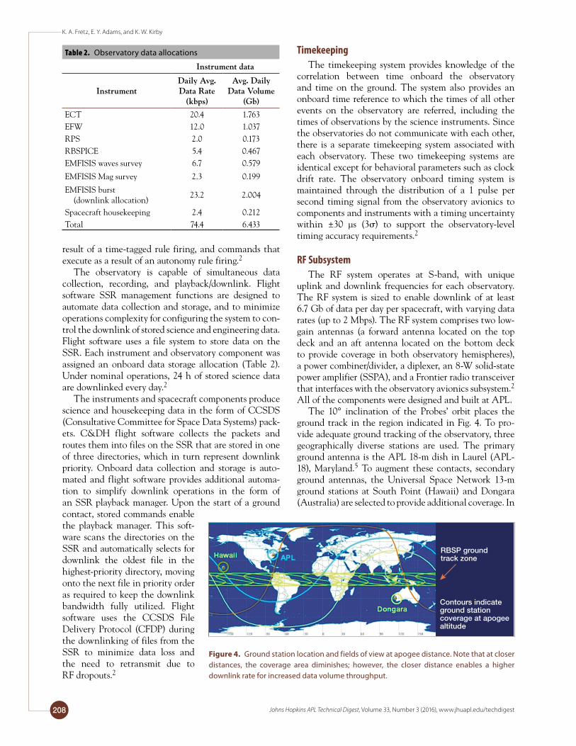
The 10° inclination of the Probes’ orbit places the ground track in the region indicated in Fig. 4. To pro-vide adequate ground tracking of the observatory, three geographically diverse stations are used. The primary ground antenna is the APL 18-m dish in Laurel (APL-18), Maryland.5 To augment these contacts, secondary ground antennas, the Universal Space Network 13-m ground stations at South Point (Hawaii) and Dongara (Australia) are selected to provide additional coverage. In
Table 2. Observatory data allocations
Instrumentdata
InstrumentDailyAvg.DataRate
(kbps)
Avg.DailyDataVolume
(Gb)
ECT 20.4 1.763EFW 12.0 1.037RPS 2.0 0.173RBSPICE 5.4 0.467EMFISIS waves survey 6.7 0.579
EMFISIS Mag survey 2.3 0.199
EMFISIS burst (downlink allocation)
23.2 2.004
Spacecraft housekeeping 2.4 0.212Total 74.4 6.433
RBSP groundtrack zone
Contours indicateground stationcoverage at apogeealtitude
Figure 4. Ground station location and fields of view at apogee distance. Note that at closer distances, the coverage area diminishes; however, the closer distance enables a higher downlink rate for increased data volume throughput.

The Van Allen Probes Observatories: Overview and Operation to Date
Johns Hopkins APL Technical Digest, Volume 33, Number 3 (2016), www.jhuapl.edu/techdigest 209
addition, the telecommunications system is also compat-ible with the Tracking and Data Relay Satellite System.
Propulsion and Guidance and Control SubsystemsThe propulsion subsystem performs propulsive
maneuvers to maintain each observatory in an attitude, spin rate, and orbit consistent with the mission’s objec-tives, while the guidance and control (G&C) subsystem determines the attitude of each observatory. The propul-sion subsystem consists of a blow-down monopropellant hydrazine propulsion system (Aerojet) for attitude con-trol, spin rate change, Delta-V, and deorbit maneuvers.3 The G&C subsystem consists of a Sun sensor (Adcole Corp.) used for timing of the open-loop propulsive maneuvers and science magnetometer (EMFISIS flux-gate magnetometer) for attitude reconstruction on the ground. The observatories are major-axis spinners with no onboard software to estimate or control their attitude or orbits. Adjustment maneuvers are designed and com-manded from the ground. Onboard G&C flight soft-ware is limited to processing Sun sensor data (i.e., Sun pulse, Head identification, and Sun offset angle) and relaying this information to the instruments via a spin pulse or via the 1-Hz time and status message. Thruster commands are decoded and executed directly by IEM hardware. Attitude is predicted and determined by using ground software tools.2
Maneuvers changing the observatory’s attitude, spin rate, or orbit use a set of eight 0.9-N (0.2 lbf) Aerojet MR-103G thrusters and components required to control the flow of propellant and monitor system health and per-formance. Each type of propulsive maneuver uses a pair of thrusters. The length of the pulses for each maneuver is chosen to minimize the amount of nutation and spin plane boom deflection during and after the maneuvers. The propellant and pressurant are stored in the three identical tanks, without diaphragms, which are spaced equally around the observatory spin axes.2
In addition, each observatory contains two ring nutation damper units that damp out the core observa-tory nutation oscillatory mode that is introduced after an observatory propulsive maneuver, with the plane of the ring position normal to the x and y axes of the observatory. These dampers are metal tubes fully filled with a silicon oil fluid and are located inside the obser-vatory structure. They were designed at APL and are as large as feasible within the geometry constraints of the observatory.2
Power SubsystemThe observatories use a direct energy transfer power
system topology that simplifies observatory electronics and minimizes electromagnetic interference generated by the power system. The power system consists of the power system electronics, battery management electron-
ics (BME), a solar array junction box, a battery, and four deployed solar array panels. It also includes the power distribution unit to distribute the switched, unswitched, and pulsed power to the observatory components; the power distribution unit receives primary power directly from the power system electronics and has command/telemetry interfaces to the IEM via a serial universal asynchronous receiver/transmitter.3
The power system electronics consist of a single fault-tolerant 16-stage sequential analog voltage control shunt regulator with maximum battery current limit. The loads are connected to the single 8-cell, 50-Ah Li-ion battery (GS Yuasa) via the power distribution unit. The nominal bus voltage is 30 V and can vary between 24 and 32 V depending on the state of charge and temperature of the battery. The primary battery charge control method is constant current followed by a constant voltage taper charge. The BME consists of an interface board and a cell shunt board. Each battery cell has a parallel-connected analog shunt used during the mission to balance the end of charge voltage of each Li-ion battery cell. Each cell shunt is limited to 0.75 A maximum current bypassed around the cell in order to limit the amount of power dissipated in the BME. The BME contains eight relays, which allow the battery cells to be disconnected from cell shunts to limit leakage cur-rent during ground operations or whenever the BME is not powered.3
The solar array consists of four deployed panels with a total active area of 3.2 m2. Each panel is approximately 0.739 m wide and 1.26 m long. The panel substrates are 25.4-mm-thick aluminum honeycomb with composite face sheets. The panel front cell side is insulated with Kapton and cocured with the graphite fiber face sheet. The back face sheet is not painted. The solar cells are triple junction cells with minimum efficiency of 28.5% (best triple junction, or BTJ) from EMCORE Photo-voltaics. The cover glass on each cell is 0.5-mm-thick cerium-doped microsheet from Qioptiq with indium tin oxide coating.2
Thermal SubsystemThe observatories use a cold-biased passive thermal
control design system to maintain the electronics and instruments within their required temperature limits. The majority of the electronics boxes are hard mounted to the inside of the spacecraft panels and decks with their internal heat going into the spacecraft structure. Local radiators on the side panels and bottom deck control the amount of heat lost to the space. Multilayer insulation blankets cover the majority of the outside of the spacecraft, including the top deck, to insulate the observatory from the Sun. Heater circuits on all the panels and decks are installed to protect the observa-tories from getting too cold. Very little heater power is
K. A. Fretz, E. Y. Adams, and K. W. Kirby
Johns Hopkins APL Technical Digest, Volume 33, Number 3 (2016), www.jhuapl.edu/techdigest210
required on orbit, and the heater circuits are provided as a fail-safe device. A few observatory components, such as the battery and several instruments, are thermally iso-lated from the spacecraft and have individual radiators, blankets, and heaters.3
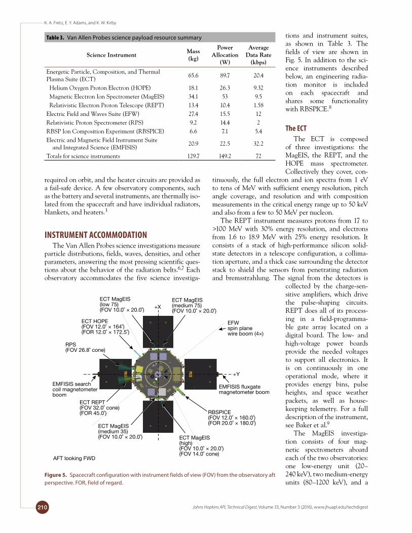
INSTRUMENT ACCOMMODATIONThe Van Allen Probes science investigations measure
particle distributions, fields, waves, densities, and other parameters, answering the most pressing scientific ques-tions about the behavior of the radiation belts.6,7 Each observatory accommodates the five science investiga-
tions and instrument suites, as shown in Table 3. The fields of view are shown in Fig. 5. In addition to the sci-ence instruments described below, an engineering radia-tion monitor is included on each spacecraft and shares some functionality with RBSPICE.8
The ECTThe ECT is composed
of three investigations: the MagEIS, the REPT, and the HOPE mass spectrometer. Collectively they cover, con-
tinuously, the full electron and ion spectra from 1 eV to tens of MeV with sufficient energy resolution, pitch angle coverage, and resolution and with composition measurements in the critical energy range up to 50 keV and also from a few to 50 MeV per nucleon.
The REPT instrument measures protons from 17 to >100 MeV with 30% energy resolution, and electrons from 1.6 to 18.9 MeV with 25% energy resolution. It consists of a stack of high-performance silicon solid-state detectors in a telescope configuration, a collima-tion aperture, and a thick case surrounding the detector stack to shield the sensors from penetrating radiation and bremsstrahlung. The signal from the detectors is
collected by the charge-sen-sitive amplifiers, which drive the pulse-shaping circuits. REPT does all of its process-ing in a field-programma-ble gate array located on a digital board. The low- and high-voltage power boards provide the needed voltages to support all electronics. It is on continuously in one operational mode, where it provides energy bins, pulse heights, and space weather packets, as well as house-keeping telemetry. For a full description of the instrument, see Baker et al.9
The MagEIS investiga-tion consists of four mag-netic spectrometers aboard each of the two observatories: one low-energy unit (20–240 keV), two medium-energy units (80–1200 keV), and a
Table 3. Van Allen Probes science payload resource summary
ScienceInstrumentMass(kg)
PowerAllocation
(W)
AverageDataRate
(kbps)
Energetic Particle, Composition, and Thermal Plasma Suite (ECT)
65.6 89.7 20.4
Helium Oxygen Proton Electron (HOPE) 18.1 26.3 9.32 Magnetic Electron Ion Spectrometer (MagEIS) 34.1 53 9.5 Relativistic Electron Proton Telescope (REPT) 13.4 10.4 1.58Electric Field and Waves Suite (EFW) 27.4 15.5 12Relativistic Proton Spectrometer (RPS) 9.2 14.4 2RBSP Ion Composition Experiment (RBSPICE) 6.6 7.1 5.4Electric and Magnetic Field Instrument Suite and Integrated Science (EMFISIS)
20.9 22.5 32.2
Totals for science instruments 129.7 149.2 72
EMFISIS �uxgatemagnetometer boom
EMFISIS search coil magnetometer boom
RBSPICE(FOV 12.0˚ × 160.0˚)(FOR 20.0˚ × 180.0˚)
RPS(FOV 26.8˚ cone)
+X
+Y
ECT MagEIS(medium 75)(FOV 10.0˚ × 20.0˚)
ECT MagEIS(medium 35)(FOV 10.0˚ × 20.0˚)
AFT looking FWD
EFWspin plane wire boom (4×)
ECT HOPE(FOV 12.0˚ × 164˚)(FOR 12.0˚ × 172.5˚)
ECT MagEIS(low 75)(FOV 10.0˚ × 20.0˚)
ECT REPT(FOV 32.0˚ cone)(FOR 45.0˚)
ECT MagEIS(high)(FOV 10.0˚ × 20.0˚)(FOV 14.0˚ cone)
Figure 5. Spacecraft configuration with instrument fields of view (FOV) from the observatory aft perspective. FOR, field of regard.
The Van Allen Probes Observatories: Overview and Operation to Date
Johns Hopkins APL Technical Digest, Volume 33, Number 3 (2016), www.jhuapl.edu/techdigest 211
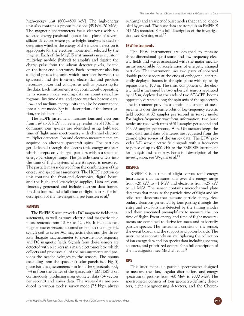
high-energy unit (800–4800 keV). The high-energy unit also contains a proton telescope (55 keV–20 MeV). The magnetic spectrometers focus electrons within a selected energy passband upon a focal plane of several silicon detectors where pulse-height analysis is used to determine whether the energy of the incident electron is appropriate for the electron momentum selected by the magnet. Each of the MagEIS instruments uses a custom multichip module (hybrid) to amplify and digitize the charge pulse from the silicon detector pixels, located on the front-end electronics. Each instrument also has a digital processing unit, which interfaces between the spacecraft and the front-end electronics and provides necessary power and voltages, as well as processing for the data. Each instrument is on continuously, operating in its science mode, sending data on count rates, his-tograms, livetime data, and space weather beacon data. Low- and medium-energy units can also be commanded into a burst mode. For full description of the investiga-tion, see Blake et al.10
The HOPE instrument measures ions and electrons from 1 eV to 50 kEV at an energy resolution of 15%. The dominant ions species are identified using foil-based time of flight mass spectrometry with channel electron multiplier detectors. Ion and electron measurements are acquired on alternate spacecraft spins. The particles get deflected through the electrostatic energy analyzer, which accepts only charged particles within a specified energy-per-charge range. The particle then enters into the time of flight system, where its speed is measured. The particle mass is derived from the combination of the energy and speed measurements. The HOPE electronics unit contains the front-end electronics, digital board, and the high- and low-voltage supplies. Data are con-tinuously generated and include electron data frames, ion data frames, and a full time-of-flight matrix. For full description of the investigation, see Funsten et al.11
EMFISISThe EMFISIS suite provides DC magnetic fields mea-
surements, as well as wave electric and magnetic field measurements from 10 Hz to 12 kHz. It includes two magnetometer sensors mounted on booms: the magnetic search coil to sense AC magnetic fields and the three-axis fluxgate magnetometer to measure low-frequency and DC magnetic fields. Signals from these sensors are detected with receivers in a main electronics box, which collects and processes all of the measurements and pro-vides the needed voltages to the sensors. The booms extending from the spacecraft solar panels (see Fig. 5) place both magnetometers 3 m from the spacecraft body (~4 m from the center of the spacecraft). EMFISIS is on continuously, producing magnetometer data (64 vectors per second) and waves data. The waves data are pro-duced in various modes: survey mode (7.5 kbps, always
running) and a variety of burst modes that can be sched-uled by ground. The burst data are stored in an EMFISIS 512-MB recorder. For a full description of the investiga-tion, see Kletzing et al.12
EFW InstrumentsThe EFW instruments are designed to measure
three-dimensional quasi-static and low-frequency elec-tric fields and waves associated with the major mecha-nisms responsible for acceleration of energetic charged particles. The instrument uses two pairs of spherical double-probe sensors at the ends of orthogonal centrip-etally deployed booms in the spin plane with tip-to-tip separations of 100 m. The third component of the elec-tric field is measured by two spherical sensors separated by ~15 m, deployed at the ends of two STACER booms oppositely directed along the spin axis of the spacecraft. The instrument provides a continuous stream of mea-surements over the entire orbit of low-frequency electric field vector at 32 samples per second in survey mode. For higher-frequency waveform information, two burst modes are used with rates of 512 samples per second and 16,000 samples per second. A 32-GB memory keeps the burst data until data of interest are requested from the ground after review of the survey data. The EFW pro-vides 3-D wave electric field signals with a frequency response of up to 400 kHz to the EMFISIS instrument for analysis and telemetry. For a full description of the investigation, see Wygant et al.13
RBSPICERBSPICE is a time of flight versus total energy
instrument that measures ions over the energy range from ~20 keV to ~1 MeV and electrons from ~25 keV to ~1 MeV. The sensor contains microchannel plate detectors that measure the particle time of flight and six solid-state detectors that measure particle energy. Sec-ondary electrons generated by ions passing through the entry and exit foils are detected by the timing anodes and their associated preamplifiers to measure the ion time of flight. Event energy and time of flight measure-ments are combined to derive ion mass and to identify particle species. The instrument consists of the sensor, the event board, and the support and power boards. The instrument is constantly on, multiplexing the collection of ion energy data and ion species data including spectra, counters, and prioritized events. For a full description of the investigation, see Mitchell et al.14
RPSThis instrument is a particle spectrometer designed
to measure the flux, angular distribution, and energy spectrum of protons from ~60 MeV to 2000 MeV. The spectrometer consists of four geometry-defining detec-tors, eight energy-sensing detectors, and the Cheren-
K. A. Fretz, E. Y. Adams, and K. W. Kirby
Johns Hopkins APL Technical Digest, Volume 33, Number 3 (2016), www.jhuapl.edu/techdigest212
kov system (for the highest-energy protons in the RPS range). It also has analog and digital processing boards to process the signals from the detectors, and high- and low-voltage power supplies. It carries an alpha calibra-tion source so it can calibrate the aging of the solid-state detectors in orbit. The instrument is on continuously and produces proton rates, direct events (which are pulse heights for valid coincidence events), and housekeeping data while staying within its orbital allocation. For a full description of the investigation, see Mazur et al.15
MISSION OPERATIONSMission operations comprises the team of mission
analysts and flight controllers, the hardware and soft-ware that comprise the ground segment, and the facili-ties involved in operating the observatories on a daily basis. Their primary tasks are to maintain healthy obser-vatories and obtain the science data placed on the SSR by the instruments.16 This section describes the opera-tions concept and key elements of the ground segment, as well as the various mission operations functions (i.e., planning and scheduling, real-time control, and perfor-mance assessment) essential to conducting a safe and efficient mission.
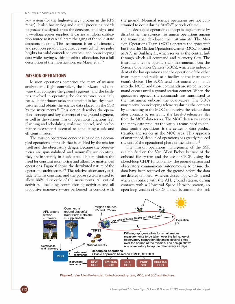
The mission operations concept is based on a decou-pled operations approach that is enabled by the mission itself and the observatory design. Because the observa-tories are spin-stabilized and nominally sun-pointing, they are inherently in a safe state. This minimizes the need for constant monitoring and allows for unattended operations. Figure 6 shows the distributed nature of the operations architecture.16 The relative observatory atti-tude remains constant, and the power system is sized to allow 100% duty cycle of the instruments. All critical activities—including commissioning activities and all propulsive maneuvers—are performed in contact with
the ground. Nominal science operations are not con-strained to occur during “staffed” periods of time.
The decoupled operations concept is implemented by distributing the science instrument operations among the teams that developed the instruments. The Mis-sion Operations Team (MOT) operates the spacecraft bus from the Mission Operations Center (MOC) located at APL in Building 21, which serves as the central hub through which all command and telemetry flow. The instrument teams operate their instruments from the Science Operation Centers (SOCs), which are indepen-dent of the bus operations and the operation of the other instruments and reside at a facility of the instrument team’s choice. The SOCs send instrument commands into the MOC, and those commands are stored in com-mand queues until a ground station contact. When the queues are opened, the commands are transmitted to the instrument onboard the observatory. The SOCs may receive housekeeping telemetry during the contacts by connecting to the MOC and receive the science data after contacts by retrieving the Level-0 telemetry files from the MOC data server. The MOC data server stores the many data products the various teams need to con-duct routine operations, is the center of data product transfer, and resides in the MOC area. This approach of unattended, decoupled operations has greatly reduced the cost of the operational phase of the mission.16
The mission operations management of the SSR is simplified on the Van Allen Probes because of the onboard file system and the use of CFDP. Using the closed-loop CFDP functionality, the ground system and observatory communicate autonomously to ensure the data have been received on the ground before the data are deleted onboard. Whereas closed-loop CFDP is used when in contact with the APL ground station, during contacts with a Universal Space Network station, an open-loop version of CFDP is used because of the lack
APL ground station• Primary
Commercialground station(s)(Near Earth Network)• Supplemental
Perigee altitudes605 and 625 km
MOCMOC
EFWSOC
EMFISISSOC
ECTSOC
PSBRSOC
RBSPICESOC
MOC
Differing apogees allow for simultaneousmeasurements to be taken over the full range ofobservatory separation distances several times over the course of the mission. The design allows one observatory to lap the other every 75 days.
TDRSS
Critical events
Decoupled operations• Basic approach based on TIMED, STEREO
Instrumentcommands
Instrumenttelemetry
Inclination10˚
Apogee altitudes 30,410 and 30,540 km
Commands and telemetry
Figure 6. Van Allen Probes distributed ground system, MOC, and SOC architecture.

The Van Allen Probes Observatories: Overview and Operation to Date
Johns Hopkins APL Technical Digest, Volume 33, Number 3 (2016), www.jhuapl.edu/techdigest 213
of ability to exchange the CFDP communications in real time.16
The primary ground station is the 18-m antenna on the APL campus and is controlled by the Satellite Communications Facility in Building 36. The 18-m dish supports the majority of contact time required to bring down the desired 5.9 Gbits of data per day per obser-vatory. During periods when the orbital geometry does not allow that support, the Universal Space Network’s South Point (Hawaii) and Dongara (Australia) stations are used. For navigation purposes, short contacts with the Dongara station are required on a weekly basis. The mission also uses communications with the Tracking and Data Relay Satellite System Space Network only for launch support, commissioning, and critical activities due to the 1-kbps downlink rate.16
The mission operations functionality is broken down into planning and scheduling, real-time control, and performance assessment functions, with each of these functions feeding into the other to facilitate safe and efficient operations. The planning function is used for scheduling observatory activities. These activities include RF control for ground station contact, SSR control, eclipse entry and exit notifications, various housekeeping functions, and maneuvers. These activi-ties, or events, comprise repeatable command sequences that may have various instantiations depending on the specific scheduling criteria. All events are classified as either routine or sporadic. Routine events are scheduled at regular intervals based on either time or contacts.16
The planning and scheduling function uses a web-based tool known as Scheduler, which is a ground soft-ware tool the MOT uses to develop the weekly schedule of events. The Scheduler tool schedules routine events automatically based on their predefined scheduling cri-teria; the MOT places sporadic events at the appropriate time in the schedule. The planning process also incor-porates the use of simulators to verify proper command sequencing for particular observatory activities. The MOT uses two types of simulators: a hardware-based simulator known as the RBSP Operations Simulator and a software-based simulator known as the Flight Accel-erated Simulation Tool. The final part of the planning process involves the final creation of contact plans and associated procedures and scripts. These are transferred to the MOC for execution during the contact.16
The real-time control function governs communica-tions between the ground and observatories during the ground station contacts; however, during normal day-to-day operations, the majority of contacts are unattended, with the exception of critical activities such as maneu-vers and possible anomaly recovery activities. During both real-time and unattended contacts, the spacecraft housekeeping telemetry is evaluated for state of health and the ground system is set up to provide remote noti-fication of specific alarms to the MOT for spacecraft
alarms and to the instrument/SOC teams for specific instrument alarms. After the initial state-of-health eval-uation, the SSR downlink is initiated. Spacecraft com-manding is then performed, followed by the opening of the different SOC command queues so that instrument commands that had been waiting are uplinked.16
To downlink the amount of science data acquired on the SSR on a daily basis, the MOT schedules approxi-mately 3 h of contact time per day per observatory. To obtain this much contact time, as well as to obtain the contact time for maneuvers and other necessary activi-ties to be done outside of SSR downlinks, the Van Allen Probes use three different networks: the APL 18-m antenna (Fig. 7); Universal Space Network sta-tions in South Point (Hawaii) and in Dongara (Austra-lia) and the Tracking and Data Relay Satellite System Space Network.
The performance assessment function is broken down into two classifications. One type is routine assess-ment, which involves alarm processing and trending. Routine assessment consists of determining the status, configuration, and performance of each spacecraft sub-system. Alarm processing is performed on all observa-tory housekeeping data that are collected via the SSR as well as in real time. The alarm-processing software notifies the MOT of an unusual occurrence or condition of the observatory. The team evaluates each alarm to determine a proper course of action to understand the cause and if necessary, remedy the alarm condition.16 Trending is the periodic monitoring of critical bus com-ponents, including those components that are known to degrade over time. The MOT reviews the plots on a daily, weekly, monthly, quarterly, and annual basis to monitor for any usual occurrences or possible trends.
The other function within performance assessment is the investigation and resolution of anomalous behav-ior identified either during real-time contact or during offline assessment of performance. The performance assessment function within mission operations requires
Figure 7. APL 18-m (60-ft) antenna in Laurel, Maryland.

K. A. Fretz, E. Y. Adams, and K. W. Kirby
Johns Hopkins APL Technical Digest, Volume 33, Number 3 (2016), www.jhuapl.edu/techdigest214
further investigation so that the team can understand the cause and to determine a path of resolution. In some cases, the resolution may involve changes to pro-cesses, procedures, command sequences, and possibly alarms. Anomaly reports are written when an anoma-lous condition is first identified, and the resolution is documented as part of the anomaly closeout process. The performance assessment function closes the loop within the mission operations process by feeding into the planning function any changes necessary to address issues uncovered during the real-time or assessment aspects so that the team can continue to try to improve operations efficiency.16
OBSERVATORY TRENDINGIn addition to the routine trending mission opera-
tions team members perform as a part of their perfor-mance assessment, the Van Allen Probes spacecraft team and instrument teams also play a role in the moni-toring and trending process. The spacecraft subsystem leads monitor trends within their subsystems but also compile monthly plots for quick review. In addition, quarterly memos are produced with a summary of each subsystem’s performance. The science instrument opera-tions teams routinely monitor their telemetry and report status in monthly progress reports and participate in mission operations weekly telecons.8 Finally, the Van Allen Probes project team conducts trending reviews, which are discussed below, every 6 months.
The Van Allen Probes trending review serves as a formal opportunity for each subsystem and instrument team to report status to the project team and to identify and evaluate any long-term trends. Each subsystem and instrument lead engineer presents to the project team the findings on the data collected during the previous 6 months of operation, with a focus on the following: the overall subsystem or instrument performance, an over-view of major subsystem activities, anomalous behaviors (which includes addressing any open anomaly reports), changes in nominal operating conditions, trends that could impact future operations and operational changes, and limit adjustments needed to accommodate changes in the mission (i.e., longer eclipses and attitude adjust-ments). The project team then assesses the overall space-craft and instrument health performance and identifies any changes that could be made to improve performance or any preventative actions that could be taken to miti-gate against future failures or degraded performance.8
The Van Allen Probes use the L3 InControl satellite command and control software for monitoring and con-trolling the satellites and ground equipment. Subsystem and instrument leads use several InControl capabilities to aid the daily telemetry monitoring and long-term trending review process such as the ability to distrib-ute data to users and ingest data from other sources,
archiving of both spacecraft and ground system data (i.e., raw and processed data, command histories, and event logs) for later playback or retrieval access, and data retrieval of archived data by time range.8
CONCLUSIONThe Van Allen Probes have traversed the radiation
belts for the past 3 years and performed successfully with minimal support required. The observatories have returned more than twice the expected science data. These science data have enabled major new discoveries about the radiation belts, including a temporary third radiation belt, acceleration energy within the belts them-selves, and a nearly impenetrable barrier that prevents the fastest and most energetic electrons from reaching Earth. Preparations are under way to define new science objectives, orbit variations, and spacecraft configuration changes that will provide enhanced science data for an extended mission. The Van Allen Probes have demon-strated that they are well designed to support continued operations in the Van Allen radiation belts and have the capacity to make further contributions to studies of the Earth–Sun system.
ACKNOWLEDGMENTS: Parts of this article were previously published in a 2013 volume of Space Science Reviews (vol. 179, no. 1, pp. 59–125) and then in the book The Van Allen Probes Mission, edited by Nicola Fox and James L. Burch (Springer US, New York, 2014). The book was published under the Creative Commons license CC-BY. The authors thank the NASA Living With a Star pro-gram and the Science Mission Directorate for support of this work, as well as the efforts of the many RBSP team members whose work will contribute to the success of this mission.
REFERENCES 1Stratton, J., and Fox, N. J., “Radiation Belt Storm Probes (RBSP) Mis-
sion Overview,” in Proc. 2012 IEEE Aerospace Conf., Big Sky, MT, pp. 1–10 (2012).
2Kirby, K., Bushman, S., Butler, M., Conde, R., Fretz, K., et al., “Radia-tion Belt Storm Probe Spacecraft and Impact of Environment on Spacecraft Design,” in Proc. 2012 IEEE Aerospace Conf., Big Sky, MT, pp. 1–20 (2012).
3Fretz, K., Kirby, K., Marsh, D., and Stratton, J., “Overview of Radia-tion Belt Storm Probes Fault Management System,” in Proc. 2013 IEEE Aerospace Conf., Big Sky, MT, pp. 1–12 (2013).
4Reid, W. M., and Monaco, C. A., “Flight Software Application Framework Simplifies Development for RBSP Observatory,” in Proc. IEEE Aerospace Conf., Big Sky, MT, pp. 1–7 (2012).
5Copeland, D. J., DeBoy, C. C., Royster, D. W., Dove, W. C., Sriniva-san, D. K., et al., “The APL 18.3m Station Upgrade and Its Applica-tion to Lunar Missions,” in Proc. 2010 IEEE Aerospace Conf., Big Sky, MT, pp. 1–10 (2010).
6Sibeck, D. G., Mauk, B. H., Grebowsky, J. M., and Fox, N. J, “The Living With a Star Radiation Belt Storm Probes Mission and Related Missions of Opportunity,” in Proc. American Geophysical Union Meet-ing, Greenbelt, MD (2006).

The Van Allen Probes Observatories: Overview and Operation to Date
Johns Hopkins APL Technical Digest, Volume 33, Number 3 (2016), www.jhuapl.edu/techdigest 215
7Ukhorskiy, A., Mauk, B., Fox, N., Sibek, D., and Grebowsky, J., “Radia-tion Belt Storm Probes: Resolving Fundamental Physics with Practical Consequences,” J. Atmos. Sol.-Terr. Phys. 73(11–12), 1417–1424 (2011).
8Kirby, K., Fretz, K., Goldsten, J., and Maurer, R., “Successes and Chal-lenges of Operating the Van Allen Probes Mission in the Radiation Belts,” Proc. 2015 IEEE Aerospace Conf., Big Sky, MT, pp. 1–18 (2015).
9Baker, D. N., Kanekal, S. G., Hoxie, V. C., Batiste, S., Bolton, M., et al., “The Relativistic Electron-Proton Telescope (REPT) Instru-ment on Board the Radiation Belt Storm Probes (RBSP) Spacecraft: Characterization of Earth’s Radiation Belt High-Energy Particle Pop-ulations,” The Van Allen Probes Mission, N. Fox and J. L. Burch (eds.), New York, Springer Science+Business Media, pp. 337–381 (2014).
10Blake, J. B., Carranza, P. A., Claudepierre, S. G., Clemmons, J. H., and Crain, W. R. Jr., “The Magnetic Electron Ion Spectrometer (MagEIS) Instruments Aboard the Radiation Belt Storm Probes (RBSP) Space-craft,” Space Sci. Rev. 179(1), 383–421 (2013).
11Funsten, H. O., Skoug, R. M., Guthrie, A. A., MacDonald, E. A., and Baldonado, J. R., “Helium, Oxygen, Proton, and Electron (HOPE)
THE AUTHORS
Kristin A. Fretz is a systems engineer in APL’s Space Exploration Sector. She led the fault management team for the Van Allen Probes mission during the development, integration, and test phases of the project and is currently serving as the Mission Systems Engineer for the extended mission. Elena Y. Adams is a systems engineer in APL’s Space Exploration Sector. She was a payload systems engineer for the Van Allen Probes, responsible for the ECT suite: MagEIS, HOPE, and REPT. Karen W. Kirby is a member of the Principal Professional Staff and a spacecraft and mission systems engineer in APL’s Space Exploration Sector. Karen led the Van Allen Probes spacecraft systems engineering team during the development, integration, and test phases of the project. She served as the Van Allen Probes mission Systems Engineer after launch while the two probes operated and successfully completed the primary science phase of the mission. For further information on the work reported here, contact Kristin Fretz. Her e-mail address is [email protected].
Mass Spectrometer for the Radiation Belt Storm Probes Mission,” Space Sci. Rev. 179(1), 423–484 (2013).
12Kletzing, C. A., Kurth, W. S., Acuna, M., MacDowall, R. J., and Torbert, R. B., “The Electric and Magnetic Field Instrument Suite and Integrated Science (EMFISIS) on RBSP,” Space Sci. Rev. 179(1), 127–181 (2013).
13Wygant, J. R., Bonnell, J. W., Goetz, K., Ergun, R. E., and Mozer, F. S., “The Electric Field and Waves Instruments on the Radiation Belt Storm Probes Mission,” Space Sci. Rev. 179(1), 183–220 (2013).
14Mitchell, D. G., Lanzerotti, L. J., Kim, C. K., Stokes, M., and Ho, G., “Radiation Belt Storm Probes Ion Composition Experiment (RBSPICE),” Space Sci. Rev. 179(1), 263–308 (2013).
15Mazur, J., Friesen, L., Lin, A., Mabry, D., and Katz, N., “The Relativ-istic Proton Spectrometer (RPS) for the Radiation Belt Storm Probes Mission,” Space Sci. Rev. 179(1), 221–261 (2013).
16Stratton, J. M., Harvey, R. J., and Heyler, G. A., “Mission Overview for the Radiation Belt Storm Probes Mission,” Space Sci. Rev. 179(1), 29–57 (2013).