Embed Size (px)
Citation preview
The Verilog Hardware Description Language
Professor Don Thomas
Carnegie Mellon University (CMU)[email protected]
http://www.ece.cmu.edu/~thomas
This is not one cohesive presentation on Verilog. The slides contained here are collected from different CMU classes at various academic levels.
These slides are provided as an alternate aid to learning the language. You may find them helpful.
Send bug reports to the above address — there are some!
The Verilog Hardware Description Language, Fifth Edition is available from Kluwer Academic Publishers, http://www.wkap.com. Phone: 781-871-6600.
Use or reproduction of the information provided in this file for commercial gain is strictly prohibited. Explicit permission is given for the reproduction and use of this information in an instructional setting.
Representation: Structural Models
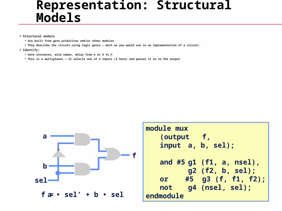
Structural models Are built from gate primitives and/or other modules They describe the circuit using logic gates — much as you would see in an implementation of a circuit.
Identify: Gate instances, wire names, delay from a or b to f. This is a multiplexor — it selects one of n inputs (2 here) and passes it on to the output
module mux (output f, input a, b, sel);
and #5 g1 (f1, a, nsel),g2 (f2, b, sel);
or #5 g3 (f, f1, f2);not g4 (nsel, sel);
endmodule
a
b
f
sel
f = a • sel’ + b • sel
Representation: Gate-Level Models
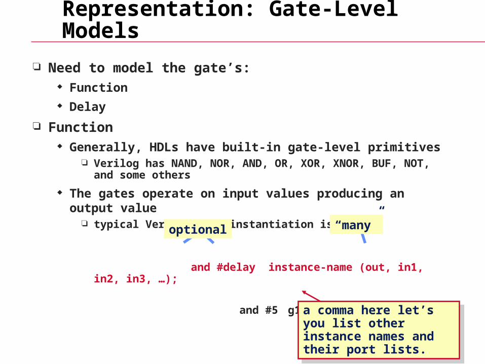
Need to model the gate’s: Function Delay
Function Generally, HDLs have built-in gate-level primitives
Verilog has NAND, NOR, AND, OR, XOR, XNOR, BUF, NOT, and some others
The gates operate on input values producing an output value typical Verilog gate instantiation is:
and #delay instance-name (out, in1, in2, in3, …);
and #5 g1 (f1, a, nsel);
optional “many”
a comma here let’s you list other instance names and their port lists.
a comma here let’s you list other instance names and their port lists.
Four-Valued Logic
Verilog Logic Values The underlying data representation allows for any bit to have one of four
values 1, 0, x (unknown), z (high impedance) x — one of: 1, 0, z, or in the state of change z — the high impedance output of a tri-state gate.
What basis do these have in reality? 0, 1 … no question z … A tri-state gate drives either a zero or one on its output…and if it’s not
doing that, its output is high impedance (z). Tri-state gates are real devices and z is a real electrical affect.
x … not a real value. There is no real gate that drives an x on to a wire. x is used as a debugging aid. x means the simulator can’t determine the answer and so maybe you should worry! All values in a simulation start as x.
BTW … Verilog keeps track of more values than these in some situations.
Four-Valued Logic
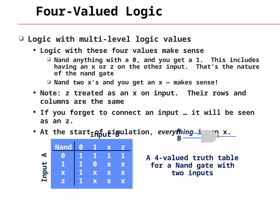
Logic with multi-level logic values Logic with these four values make sense
Nand anything with a 0, and you get a 1. This includes having an x or z on the other input. That’s the nature of the nand gate
Nand two x’s and you get an x — makes sense!
Note: z treated as an x on input. Their rows and columns are the same
If you forget to connect an input … it will be seen as an z. At the start of simulation, everything is an x.
Nand 0 1 x z 0 1 1 1 1 1 1 0 x x x 1 x x x z 1 x x x
A 4-valued truth table for a Nand gate with two inputs
Inp
ut
A
Input B AB
Concurrent activity
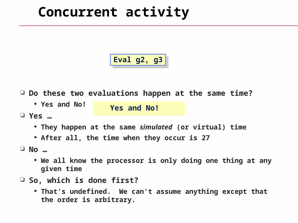
Do these two evaluations happen at the same time? Yes and No!
Yes … They happen at the same simulated (or virtual) time After all, the time when they occur is 27
No … We all know the processor is only doing one thing at any given time
So, which is done first? That’s undefined. We can’t assume anything except that the order
is arbitrary.
Eval g2, g3Eval g2, g3
Yes and No!
Concurrent Activity
The point is In the real implementation, all activity will be concurrent Thus the simulator models the elements of the system as being
concurrent in simulated time The simulator stands on its head trying to do this!
Thus, Even though the simulator executes each element of the design
one at a time … … we’ll call it concurrent
Delay
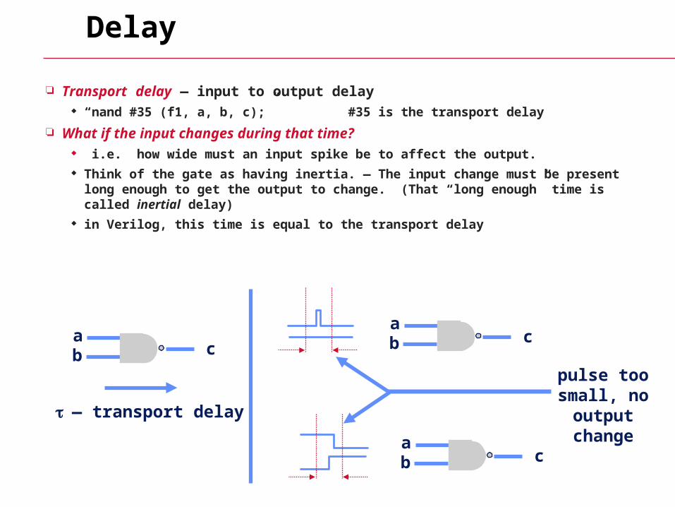
Transport delay — input to output delay “nand #35 (f1, a, b, c);” #35 is the transport delay
What if the input changes during that time? i.e. how wide must an input spike be to affect the output. Think of the gate as having inertia. — The input change must be present long enough
to get the output to change. (That “long enough” time is called inertial delay) in Verilog, this time is equal to the transport delay
ab c
— transport delay
ab c
ab c
pulse too small, no
output change
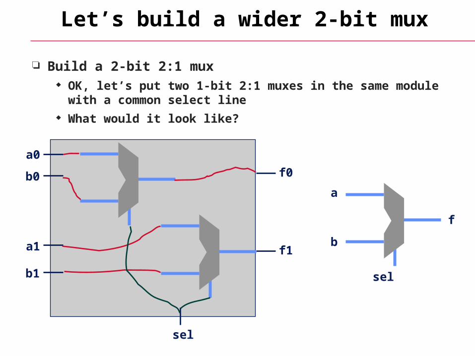
Let’s build a wider 2-bit mux
Build a 2-bit 2:1 mux OK, let’s put two 1-bit 2:1 muxes in the same module with a
common select line What would it look like?
f1
f0
a0
a1
b0
b1
sel
a
b
sel
f
Reuse!
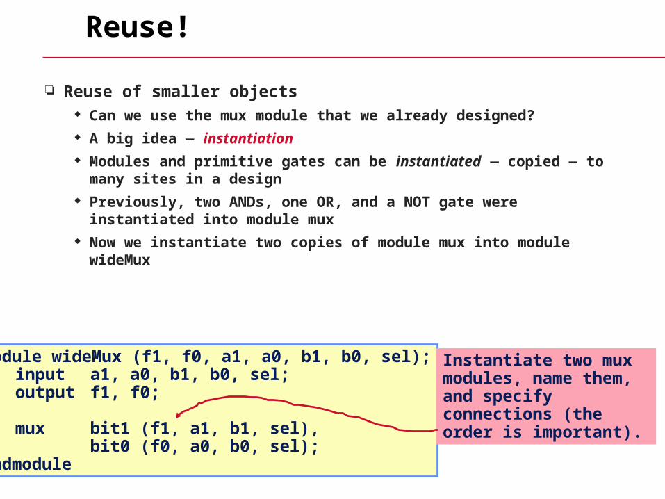
Reuse of smaller objects Can we use the mux module that we already designed? A big idea — instantiation Modules and primitive gates can be instantiated — copied — to
many sites in a design Previously, two ANDs, one OR, and a NOT gate were instantiated
into module mux Now we instantiate two copies of module mux into module wideMux
module wideMux (f1, f0, a1, a0, b1, b0, sel);input a1, a0, b1, b0, sel;output f1, f0;
mux bit1 (f1, a1, b1, sel),bit0 (f0, a0, b0, sel);
endmodule
Instantiate two mux modules, name them, and specify connections (the order is important).
Instantiation — Copies
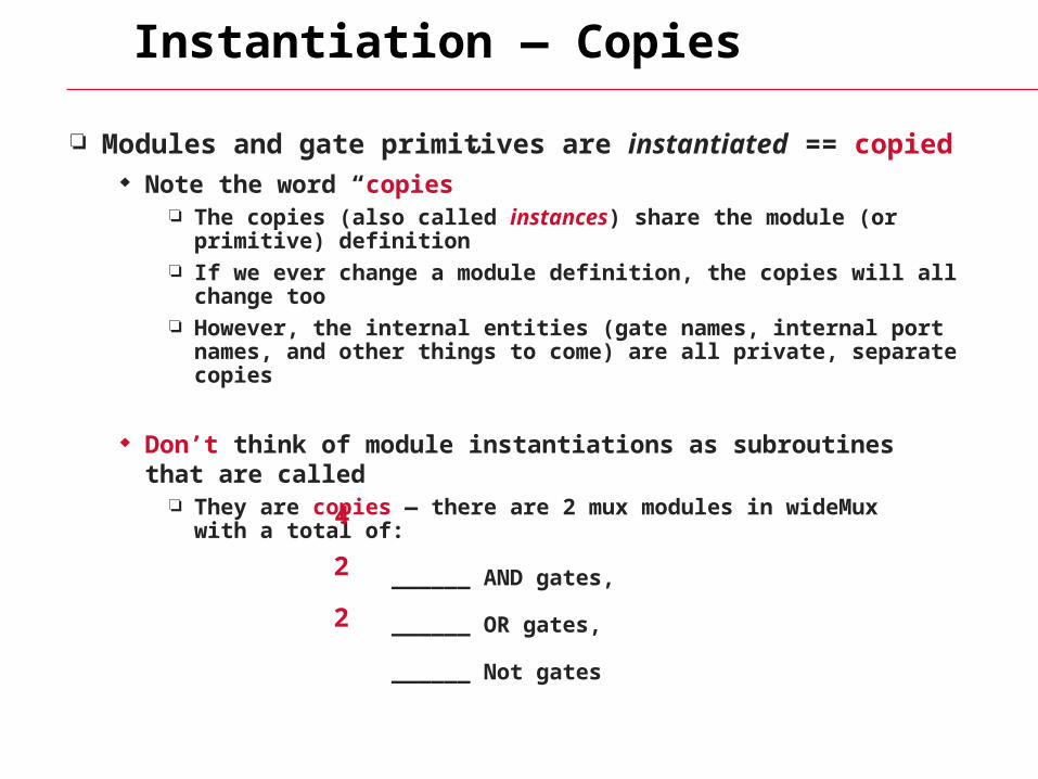
Modules and gate primitives are instantiated == copied Note the word “copies”
The copies (also called instances) share the module (or primitive) definition
If we ever change a module definition, the copies will all change too However, the internal entities (gate names, internal port names, and
other things to come) are all private, separate copies
Don’t think of module instantiations as subroutines that are called They are copies — there are 2 mux modules in wideMux
with a total of:
______ AND gates,
______ OR gates,
______ Not gates
4
2
2
Why is this cool?
In Verilog “Primitive” gates are predefined (NAND, NOR, …) Other modules are built by instantiating these gates Other modules are built by instantiating other modules, …
The design hierarchy of modules is built using instantiation Bigger modules of useful functionality are defined You can then design with these bigger modules
You can reuse modules that you’ve already built and tested You can hide the detail — why show a bunch of gates and their interconnection when you know it’s a mux!
Instantiation & hierarchy control complexity. No one designs 1M+ random gates — they use hierarchy. What are the software analogies?
How to wire modules together
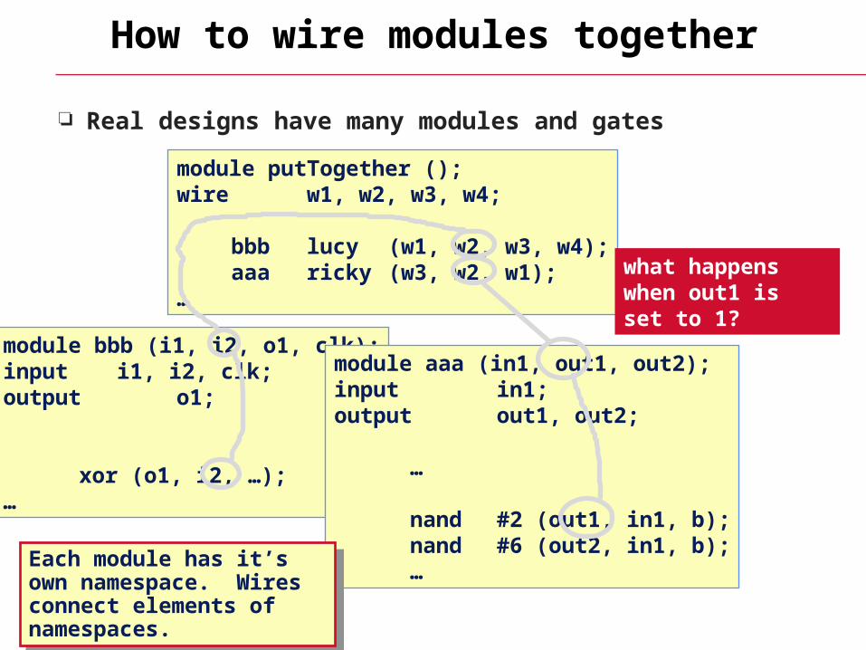
Real designs have many modules and gates
module bbb (i1, i2, o1, clk);input i1, i2, clk;output o1;
xor (o1, i2, …);…
module aaa (in1, out1, out2);input in1;output out1, out2;
…
nand #2 (out1, in1, b); nand #6 (out2, in1, b); …
module putTogether ();wire w1, w2, w3, w4;
bbb lucy (w1, w2, w3, w4); aaa ricky (w3, w2, w1);…
what happens when out1 is set to 1?
Each module has it’s own namespace. Wires connect elements of namespaces.
Each module has it’s own namespace. Wires connect elements of namespaces.
Implicit wires
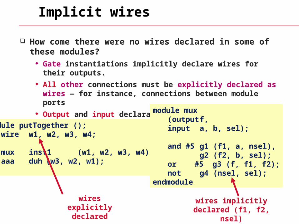
How come there were no wires declared in some of these modules?
Gate instantiations implicitly declare wires for their outputs. All other connections must be explicitly declared as wires — for
instance, connections between module ports Output and input declarations are wires
module putTogether ();wire w1, w2, w3, w4;
mux inst1 (w1, w2, w3, w4); aaa duh (w3, w2, w1);…
module mux (output f, input a, b, sel);
and #5 g1 (f1, a, nsel),g2 (f2, b, sel);
or #5 g3 (f, f1, f2);not g4 (nsel, sel);
endmodule
wires implicitly declared (f1, f2, nsel)
wires explicitly declared
How to build and test a module
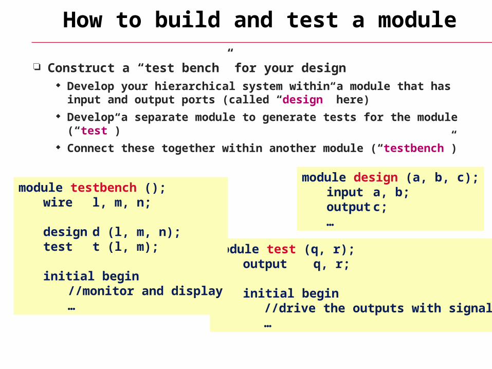
Construct a “test bench” for your design Develop your hierarchical system within a module that has input and
output ports (called “design” here) Develop a separate module to generate tests for the module (“test”) Connect these together within another module (“testbench”)
module design (a, b, c); input a, b; output c;
…
module test (q, r);output q, r;
initial begin//drive the outputs with signals…
module testbench (); wire l, m, n;
design d (l, m, n);test t (l, m);
initial begin//monitor and display…
Another view of this
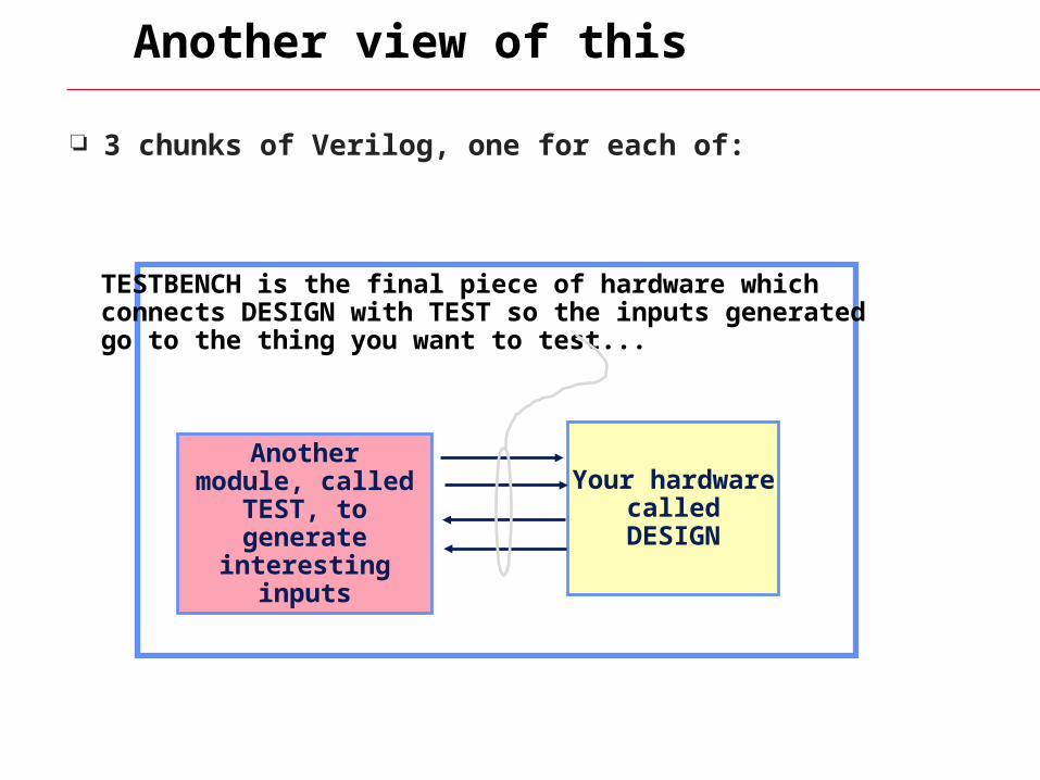
3 chunks of Verilog, one for each of:
Your hardwarecalled
DESIGN
TESTBENCH is the final piece of hardware whichconnects DESIGN with TEST so the inputs generatedgo to the thing you want to test...
Another module, called TEST, to
generate interesting inputs
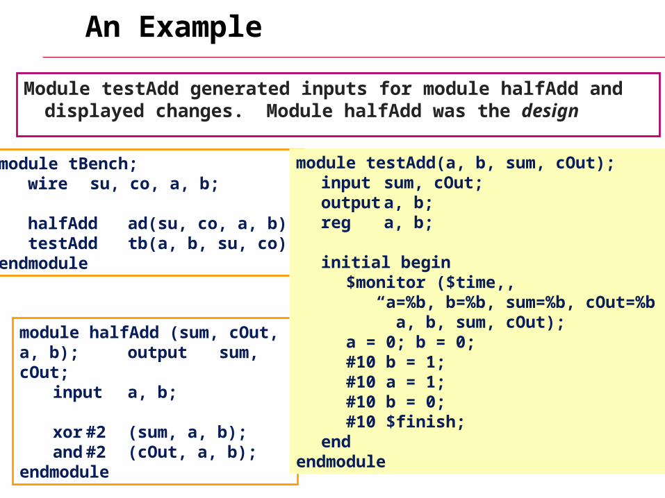
An Example
Module testAdd generated inputs for module halfAdd and displayed changes. Module halfAdd was the design
module tBench;wire su, co, a, b;
halfAdd ad(su, co, a, b);testAddtb(a, b, su, co);
endmodule
module halfAdd (sum, cOut, a, b); output sum, cOut;input a, b;
xor #2 (sum, a, b);and #2 (cOut, a, b);
endmodule
module testAdd(a, b, sum, cOut);input sum, cOut;output a, b;reg a, b;
initial begin$monitor ($time,, “a=%b, b=%b, sum=%b, cOut=%b”, a, b, sum, cOut);a = 0; b = 0;#10 b = 1;#10 a = 1;#10 b = 0;#10 $finish;
endendmodule
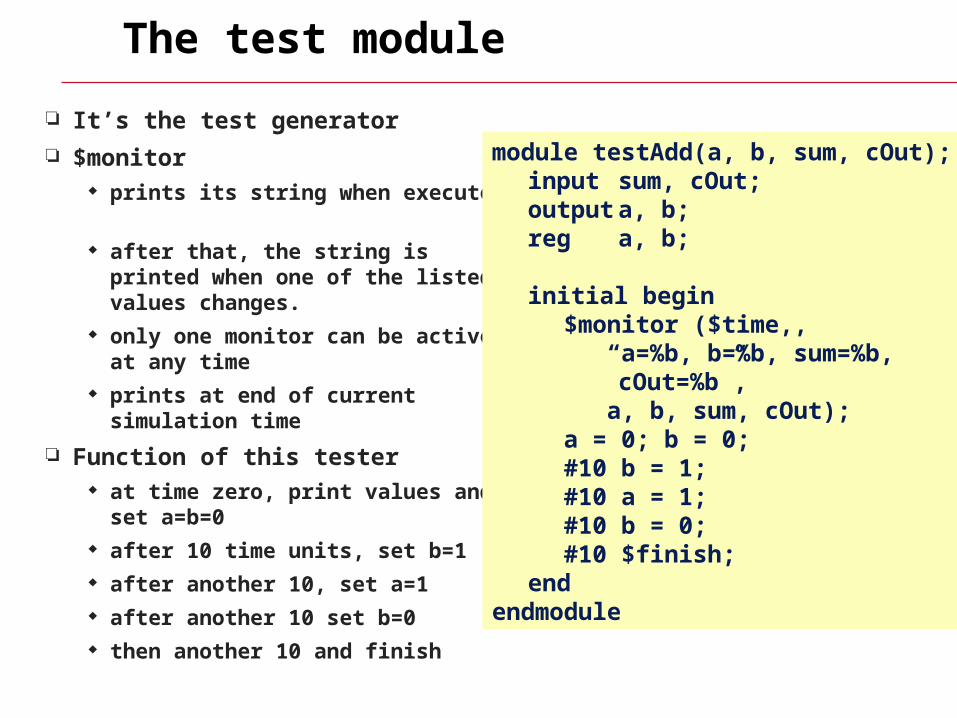
The test module
It’s the test generator
$monitor prints its string when executed. after that, the string is printed when
one of the listed values changes. only one monitor can be active at
any time prints at end of current simulation
time
Function of this tester at time zero, print values and set
a=b=0 after 10 time units, set b=1 after another 10, set a=1 after another 10 set b=0 then another 10 and finish
module testAdd(a, b, sum, cOut);input sum, cOut;output a, b;reg a, b;
initial begin$monitor ($time,, “a=%b, b=%b, sum=%b,
cOut=%b”, a, b, sum, cOut);a = 0; b = 0;#10 b = 1;#10 a = 1;#10 b = 0;#10 $finish;
endendmodule
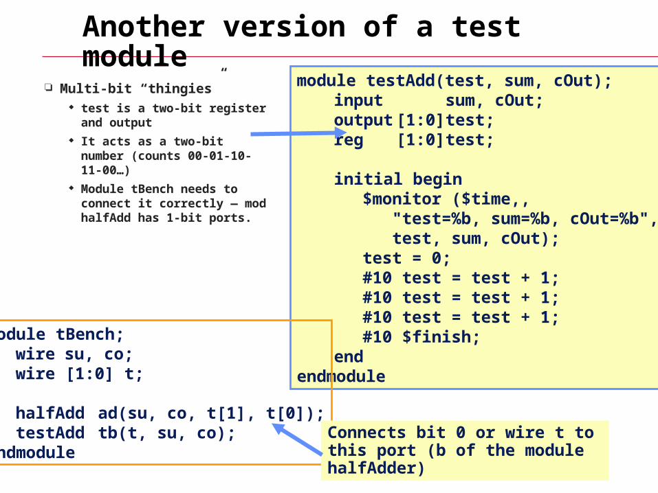
Another version of a test module
Multi-bit “thingies” test is a two-bit register
and output It acts as a two-bit number
(counts 00-01-10-11-00…) Module tBench needs to
connect it correctly — mod halfAdd has 1-bit ports.
module testAdd(test, sum, cOut);input sum, cOut;output [1:0] test;reg [1:0] test;
initial begin$monitor ($time,, "test=%b, sum=%b, cOut=%b", test, sum, cOut);test = 0;#10 test = test + 1;#10 test = test + 1;#10 test = test + 1;#10 $finish;
endendmodule
module tBench;wire su, co;wire [1:0] t;
halfAdd ad(su, co, t[1], t[0]);testAdd tb(t, su, co);
endmoduleConnects bit 0 or wire t to this port (b of the module halfAdder)
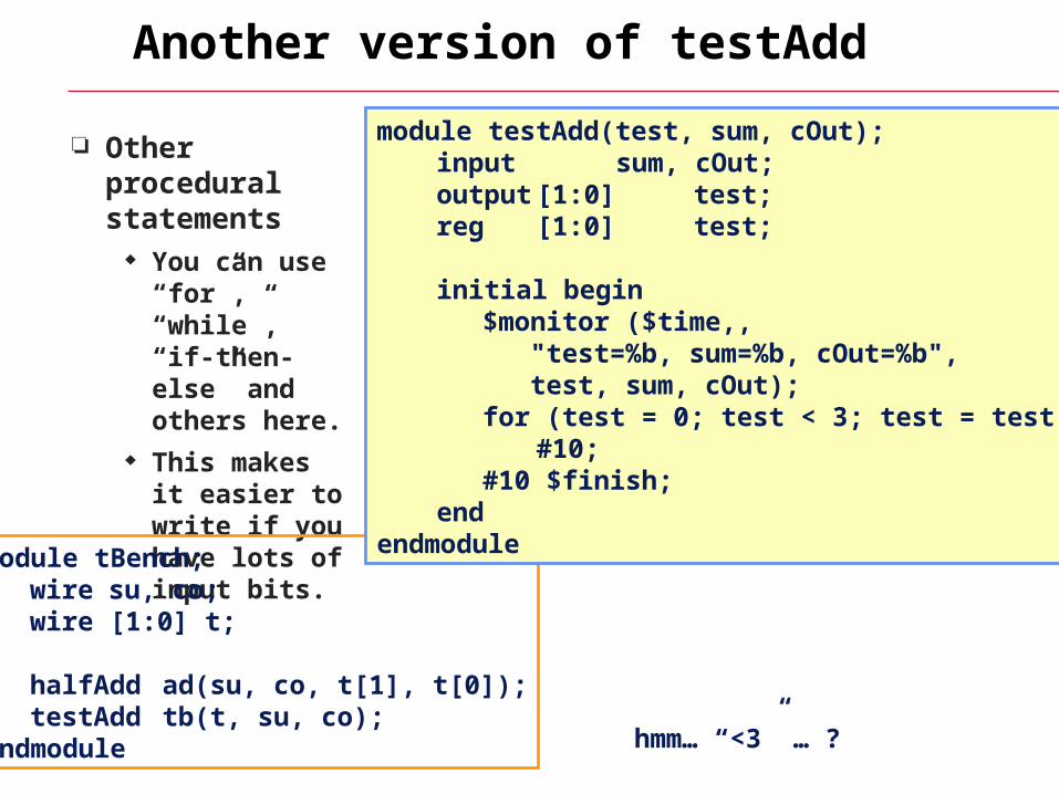
Another version of testAdd
Other procedural statements
You can use “for”, “while”, “if-then-else” and others here.
This makes it easier to write if you have lots of input bits.
module tBench;wire su, co;wire [1:0] t;
halfAdd ad(su, co, t[1], t[0]);testAdd tb(t, su, co);
endmodule
module testAdd(test, sum, cOut);input sum, cOut;output [1:0] test;reg [1:0] test;
initial begin$monitor ($time,, "test=%b, sum=%b, cOut=%b", test, sum, cOut);for (test = 0; test < 3; test = test + 1)
#10; #10 $finish;
endendmodule
hmm… “<3” … ?
Structural vs Behavioral Models
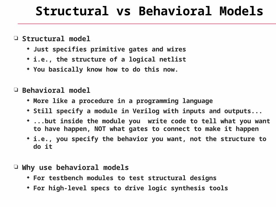
Structural model Just specifies primitive gates and wires i.e., the structure of a logical netlist You basically know how to do this now.
Behavioral model More like a procedure in a programming language Still specify a module in Verilog with inputs and outputs... ...but inside the module you write code to tell what you want to have
happen, NOT what gates to connect to make it happen i.e., you specify the behavior you want, not the structure to do it
Why use behavioral models For testbench modules to test structural designs For high-level specs to drive logic synthesis tools
How do behavioral models fit in?
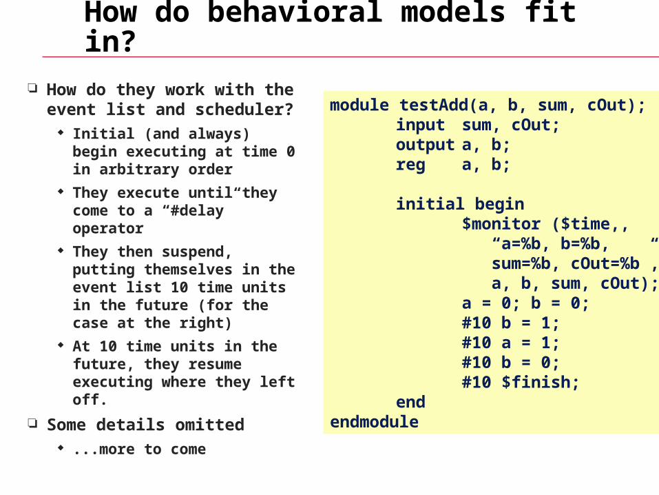
How do they work with the event list and scheduler?
Initial (and always) begin executing at time 0 in arbitrary order
They execute until they come to a “#delay” operator
They then suspend, putting themselves in the event list 10 time units in the future (for the case at the right)
At 10 time units in the future, they resume executing where they left off.
Some details omitted ...more to come
module testAdd(a, b, sum, cOut);input sum, cOut;output a, b;reg a, b;
initial begin$monitor ($time,, “a=%b, b=%b, sum=%b, cOut=%b”, a, b, sum, cOut);a = 0; b = 0;#10 b = 1;#10 a = 1;#10 b = 0;#10 $finish;
endendmodule
Two initial statements?
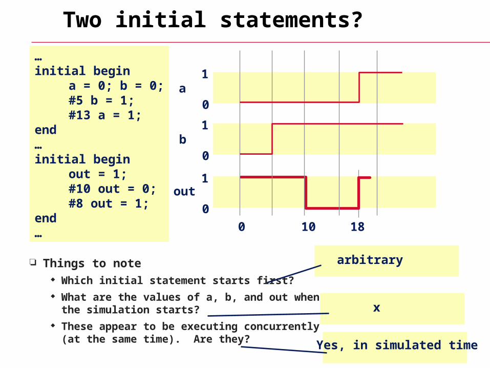
Things to note Which initial statement starts first? What are the values of a, b, and out when the
simulation starts? These appear to be executing concurrently (at
the same time). Are they?
…initial begin
a = 0; b = 0;#5 b = 1;#13 a = 1;
end…initial begin
out = 1; #10 out = 0; #8 out = 1;
end…
1
0
1
0
1
0
0 10 18
a
b
out
arbitrary
x
Yes, in simulated time
Other things you can do
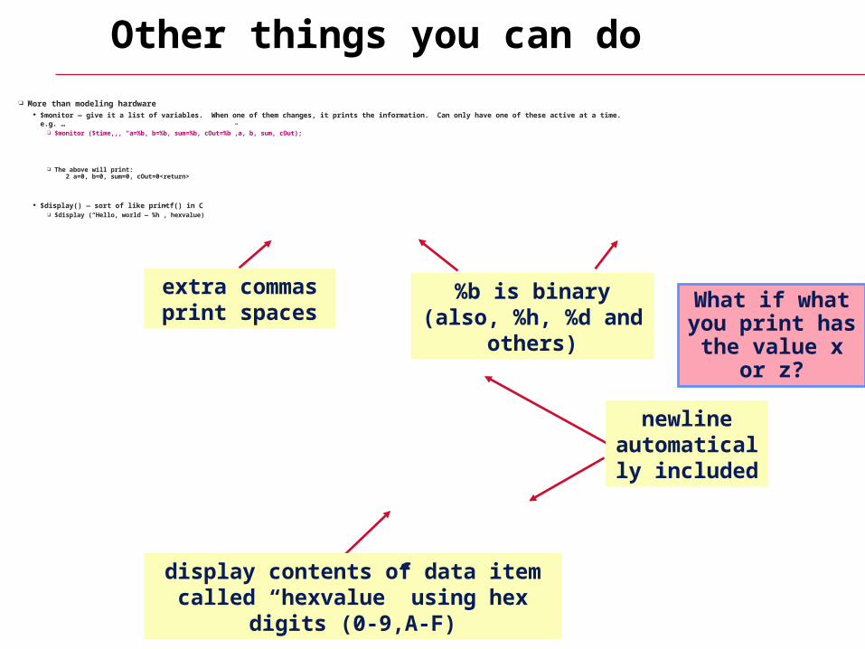
More than modeling hardware $monitor — give it a list of variables. When one of them changes, it prints the information. Can only have one of these active at a time.
e.g. … $monitor ($time,,, “a=%b, b=%b, sum=%b, cOut=%b”,a, b, sum, cOut);
The above will print: 2 a=0, b=0, sum=0, cOut=0<return>
$display() — sort of like printf() in C $display (“Hello, world — %h”, hexvalue)
extra commas print spaces
%b is binary (also, %h, %d and others)
newline automatically
included
display contents of data item called “hexvalue” using hex digits (0-9,A-F)
What if what you print has
the value x or z?
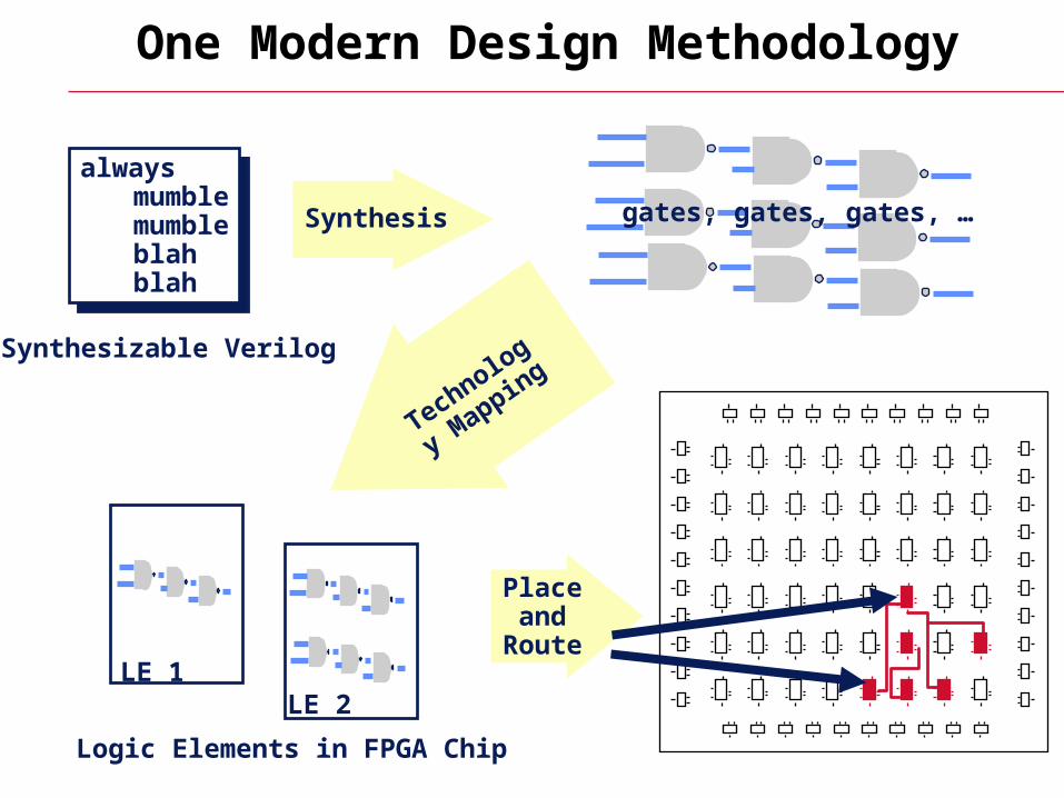
One Modern Design Methodology
alwaysmumblemumbleblahblah
alwaysmumblemumbleblahblah
Synthesizable Verilog
Synthesis
Technology
Mapping
LE 1LE 2
Place and
Route
gates, gates, gates, …
Logic Elements in FPGA Chip
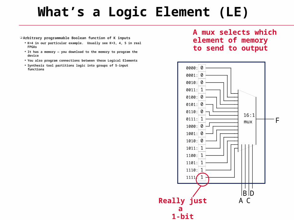
What’s a Logic Element (LE)
Arbitrary programmable Boolean function of K inputs K=4 in our particular example. Usually see K=3, 4, 5 in real FPGAs It has a memory — you download to the memory to program the
device You also program connections between these Logical Elements Synthesis tool partitions logic into groups of 5-input functions
0
0
0
1
0
0
0
1
0
0
0
1
1
1
1
1
F
ABCD
16:1mux
0000:
0001:
0010:
0011:
0100:
0101:
0110:
0111:
1000:
1001:
1010:
1011:
1100:
1101:
1110:
1111:
A mux selects whichelement of memoryto send to output
Really just a 1-bit memory
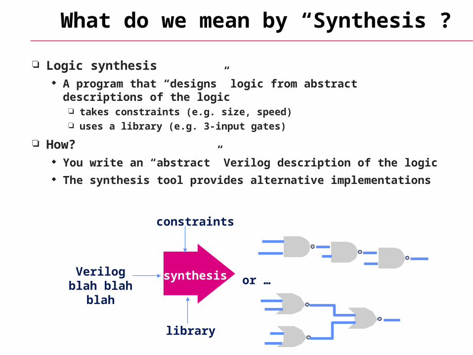
What do we mean by “Synthesis”?
Logic synthesis A program that “designs” logic from abstract descriptions of the
logic takes constraints (e.g. size, speed) uses a library (e.g. 3-input gates)
How? You write an “abstract” Verilog description of the logic The synthesis tool provides alternative implementations
Verilog blah blah blah or …synthesis
library
constraints
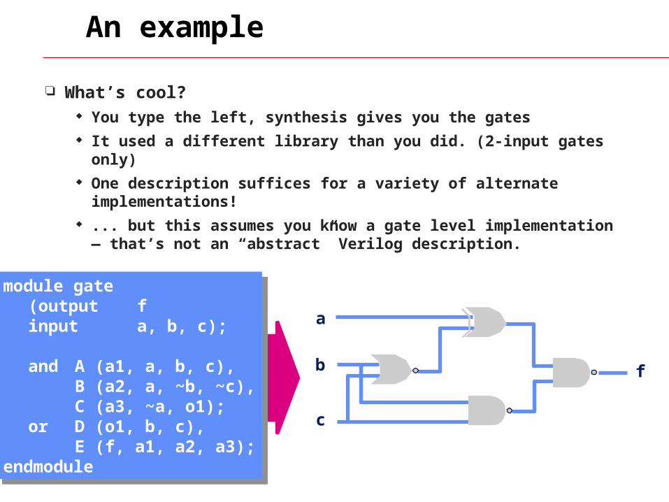
An example
What’s cool? You type the left, synthesis gives you the gates It used a different library than you did. (2-input gates only) One description suffices for a variety of alternate
implementations! ... but this assumes you know a gate level implementation —
that’s not an “abstract” Verilog description.
a
b
c
f
module gate(output finput a, b, c);
and A (a1, a, b, c),B (a2, a, ~b, ~c),C (a3, ~a, o1);
or D (o1, b, c),E (f, a1, a2, a3);
endmodule
module gate(output finput a, b, c);
and A (a1, a, b, c),B (a2, a, ~b, ~c),C (a3, ~a, o1);
or D (o1, b, c),E (f, a1, a2, a3);
endmodule
What Do We Want Here…?
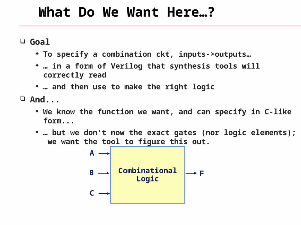
Goal To specify a combination ckt, inputs->outputs… … in a form of Verilog that synthesis tools will correctly read … and then use to make the right logic
And... We know the function we want, and can specify in C-like form... … but we don’t now the exact gates (nor logic elements); we want the
tool to figure this out.
CombinationalLogic
A
B
C
F
Behavioral Modeling
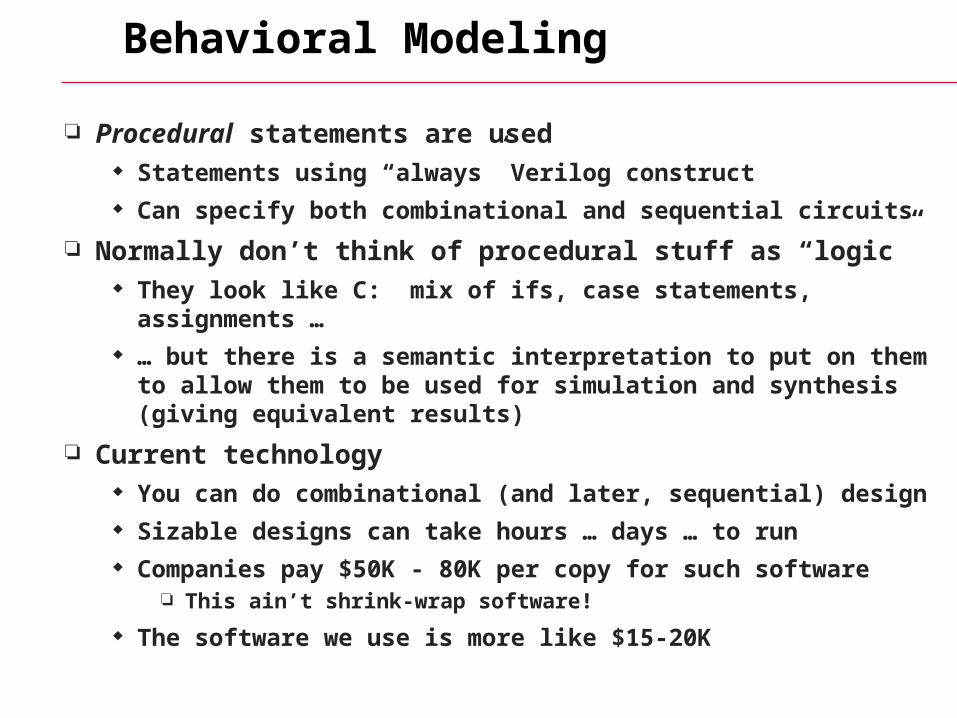
Procedural statements are used Statements using “always” Verilog construct Can specify both combinational and sequential circuits
Normally don’t think of procedural stuff as “logic” They look like C: mix of ifs, case statements, assignments … … but there is a semantic interpretation to put on them to allow them
to be used for simulation and synthesis (giving equivalent results)
Current technology You can do combinational (and later, sequential) design Sizable designs can take hours … days … to run Companies pay $50K - 80K per copy for such software
This ain’t shrink-wrap software!
The software we use is more like $15-20K
Behavioral Constructs
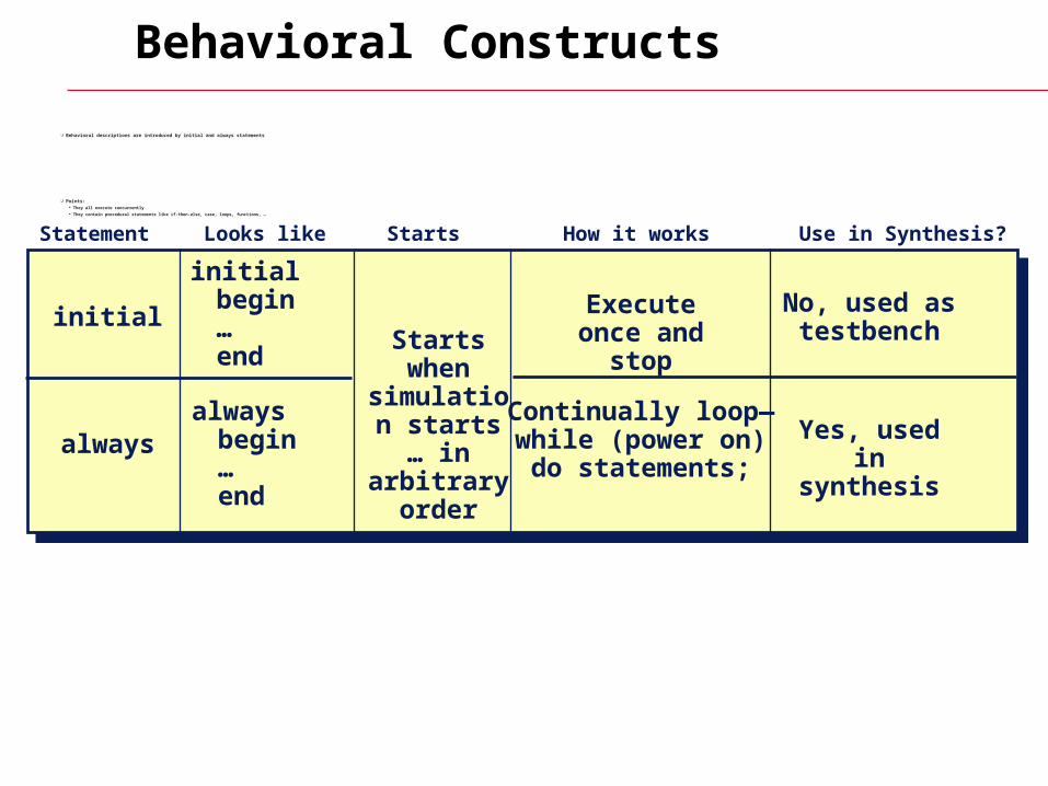
Behavioral descriptions are introduced by initial and always statements
Points: They all execute concurrently They contain procedural statements like if-then-else, case, loops, functions, …
initial
always
Starts when
simulation starts … in
arbitrary order
Execute once and stop
Continually loop—while (power on)do statements;
No, used as testbench
Yes, used in synthesis
Statement Starts How it works Use in Synthesis?Looks like
initialbegin…end
alwaysbegin…end
Statements, Registers and Wires
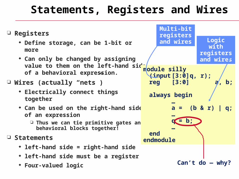
Registers Define storage, can be 1-bit or more Can only be changed by assigning value
to them on the left-hand side of a behavioral expression.
Wires (actually “nets”) Electrically connect things together Can be used on the right-hand side of an
expression Thus we can tie primitive gates and
behavioral blocks together!
Statements left-hand side = right-hand side left-hand side must be a register Four-valued logic
module silly(input [3:0] q, r);reg [3:0] a, b;
always begin…a = (b & r) | q;…q = b;…
endendmodule
Can’t do — why?
Logic with registers and wires
Multi-bit registers and wires
Behavioral Statements
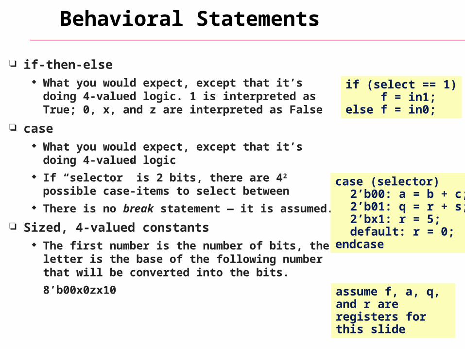
if-then-else What you would expect, except that it’s doing 4-
valued logic. 1 is interpreted as True; 0, x, and z are interpreted as False
case What you would expect, except that it’s doing 4-
valued logic If “selector” is 2 bits, there are 42 possible case-
items to select between There is no break statement — it is assumed.
Sized, 4-valued constants The first number is the number of bits, the letter is
the base of the following number that will be converted into the bits.
8’b00x0zx10
if (select == 1)f = in1;
else f = in0;
case (selector)2’b00: a = b + c;2’b01: q = r + s;2’bx1: r = 5;default: r = 0;
endcase
assume f, a, q, and r are registers for this slide
Behavioral Statements
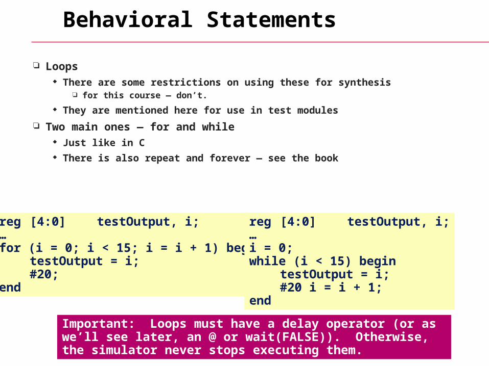
Loops There are some restrictions on using these for synthesis
for this course — don’t.
They are mentioned here for use in test modules
Two main ones — for and while Just like in C There is also repeat and forever — see the book
reg [4:0] testOutput, i;…for (i = 0; i < 15; i = i + 1) begin
testOutput = i;#20;
end
reg [4:0] testOutput, i;…i = 0; while (i < 15) begin
testOutput = i;#20 i = i + 1;
end
Important: Loops must have a delay operator (or as we’ll see later, an @ or wait(FALSE)). Otherwise, the simulator never stops executing them.
Concurrent Constructs
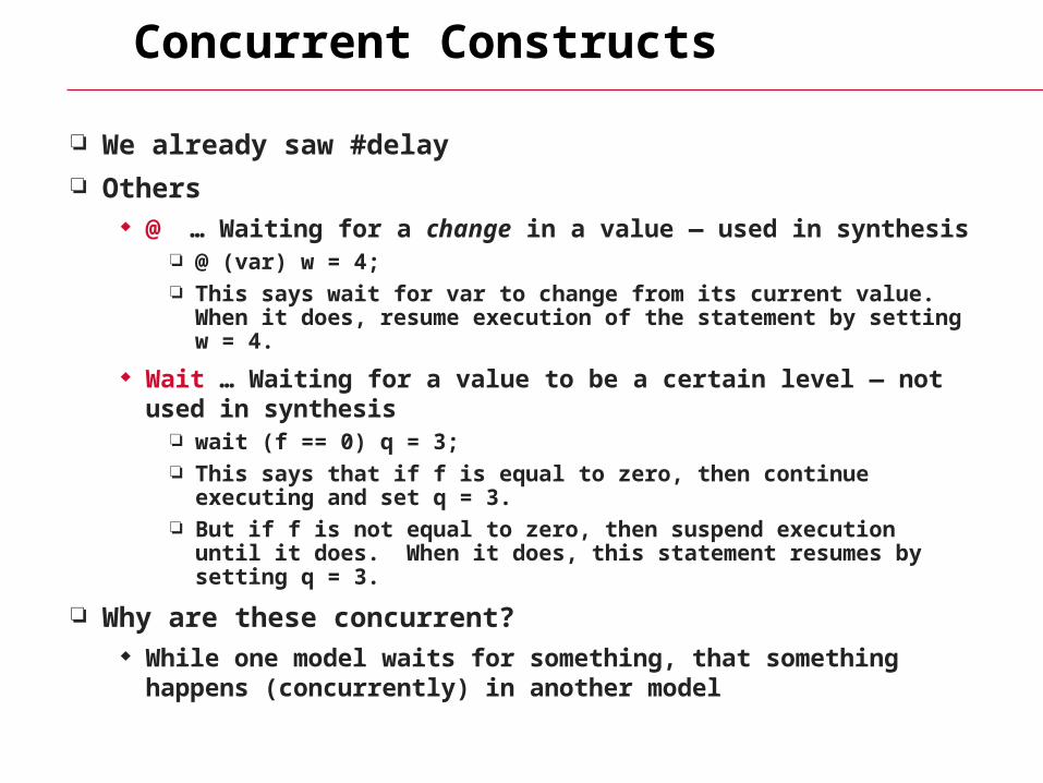
We already saw #delay
Others @ … Waiting for a change in a value — used in synthesis
@ (var) w = 4; This says wait for var to change from its current value. When it does,
resume execution of the statement by setting w = 4.
Wait … Waiting for a value to be a certain level — not used in synthesis
wait (f == 0) q = 3; This says that if f is equal to zero, then continue executing and set q =
3. But if f is not equal to zero, then suspend execution until it does.
When it does, this statement resumes by setting q = 3.
Why are these concurrent? While one model waits for something, that something happens
(concurrently) in another model
FAQs: behavioral model execution
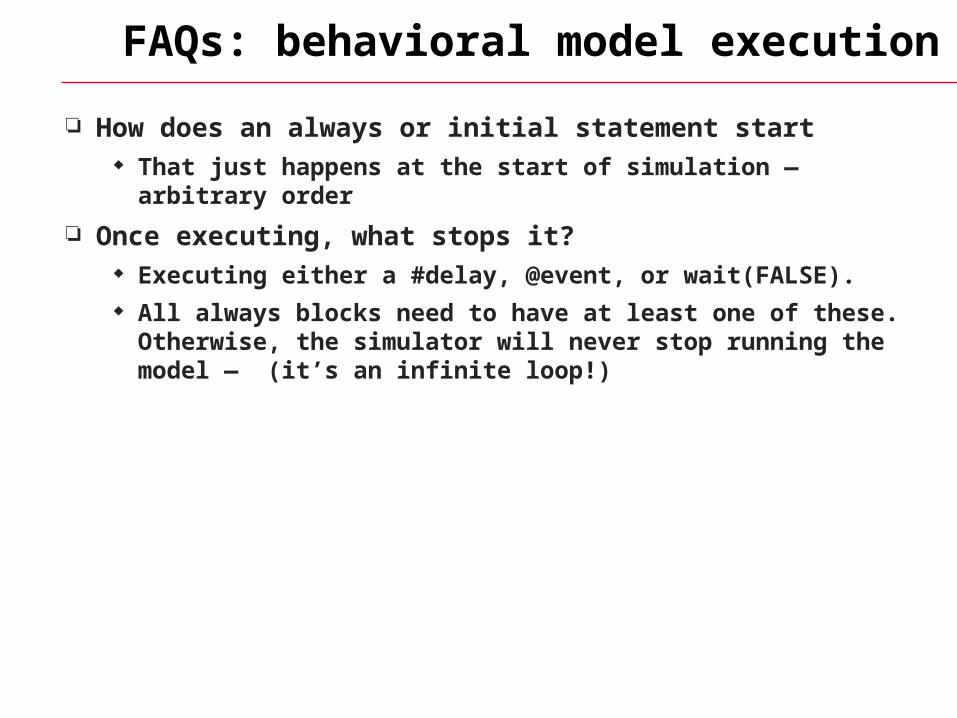
How does an always or initial statement start That just happens at the start of simulation — arbitrary order
Once executing, what stops it? Executing either a #delay, @event, or wait(FALSE). All always blocks need to have at least one of these. Otherwise, the
simulator will never stop running the model — (it’s an infinite loop!)
More FAQs
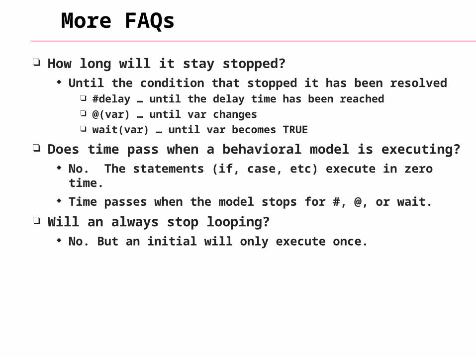
How long will it stay stopped? Until the condition that stopped it has been resolved
#delay … until the delay time has been reached @(var) … until var changes wait(var) … until var becomes TRUE
Does time pass when a behavioral model is executing? No. The statements (if, case, etc) execute in zero time. Time passes when the model stops for #, @, or wait.
Will an always stop looping? No. But an initial will only execute once.
A Combinational Circuit
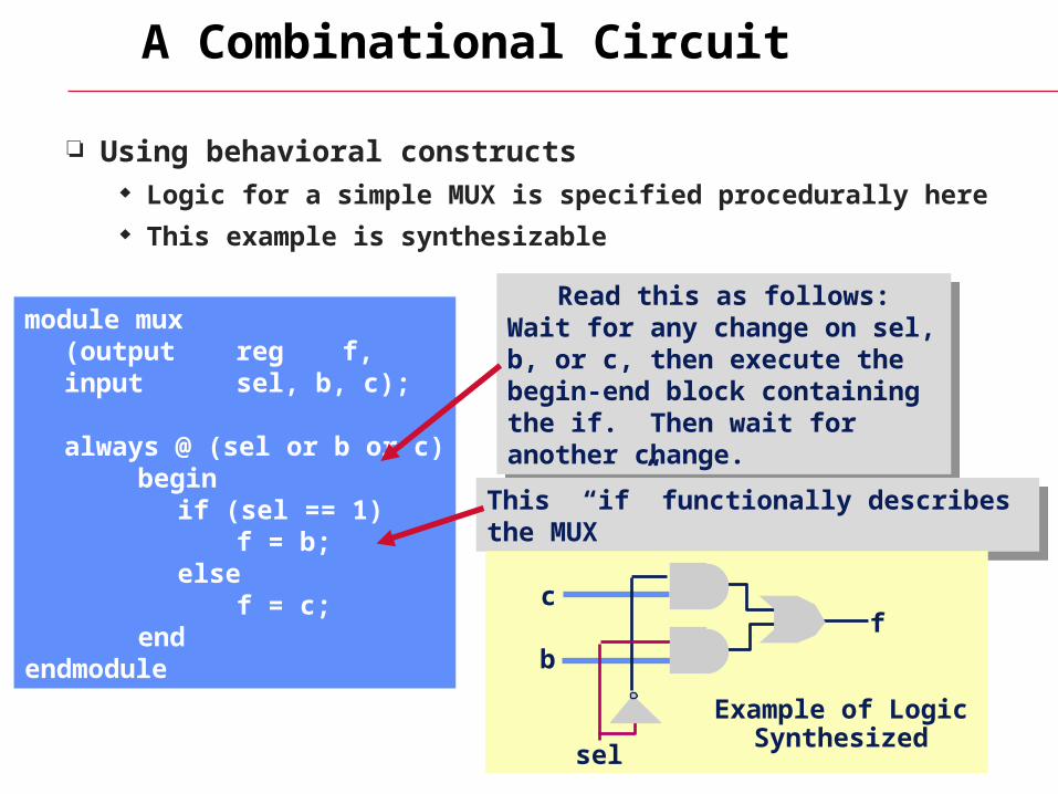
Using behavioral constructs Logic for a simple MUX is specified procedurally here This example is synthesizable
module mux(output reg f,input sel, b, c);
always @ (sel or b or c)begin
if (sel == 1)f = b;
elsef = c;
endendmodule
Read this as follows:Wait for any change on sel, b, or c, then execute the begin-end block containing the if. Then wait for another change.
Read this as follows:Wait for any change on sel, b, or c, then execute the begin-end block containing the if. Then wait for another change.
This “if” functionally describes the MUXThis “if” functionally describes the MUX
sel
fb
c
Example of Logic Synthesized
Huh? Is it really correct?
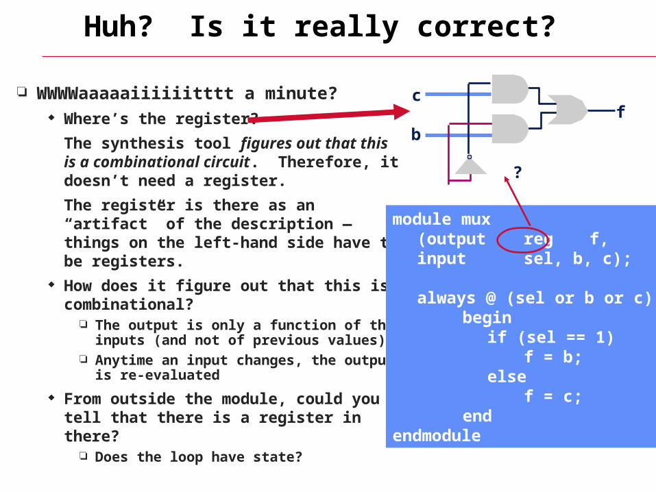
WWWWaaaaaiiiiiitttt a minute? Where’s the register?
The synthesis tool figures out that this is a combinational circuit. Therefore, it doesn’t need a register.
The register is there as an “artifact” of the description — things on the left-hand side have to be registers.
How does it figure out that this is combinational?
The output is only a function of the inputs (and not of previous values)
Anytime an input changes, the output is re-evaluated
From outside the module, could you tell that there is a register in there?
Does the loop have state?
fb
c
module mux(output reg f,input sel, b, c);
always @ (sel or b or c)begin
if (sel == 1)f = b;
elsef = c;
endendmodule
?
Synthesis Template
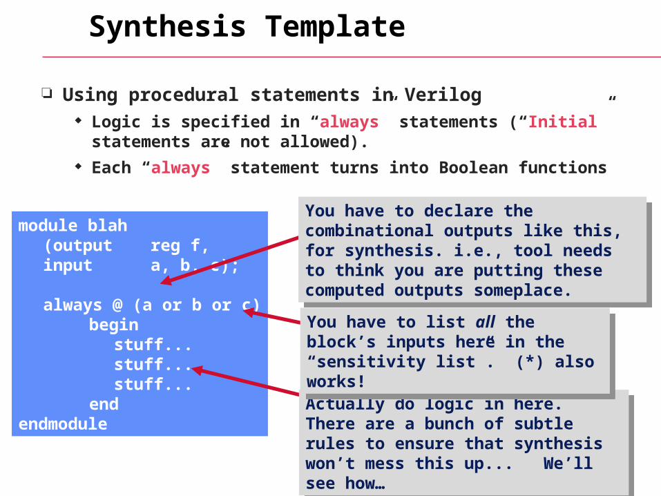
Using procedural statements in Verilog Logic is specified in “always” statements (“Initial” statements are not
allowed). Each “always” statement turns into Boolean functions
module blah(output reg f,input a, b, c);
always @ (a or b or c)begin
stuff...stuff...stuff...
endendmodule
You have to declare the combinational outputs like this, for synthesis. i.e., tool needs to think you are putting these computed outputs someplace.
You have to declare the combinational outputs like this, for synthesis. i.e., tool needs to think you are putting these computed outputs someplace.
Actually do logic in here. There are a bunch of subtle rules to ensure that synthesis won’t mess this up... We’ll see how…
Actually do logic in here. There are a bunch of subtle rules to ensure that synthesis won’t mess this up... We’ll see how…
You have to list all the block’s inputs here in the “sensitivity list”. (*) also works!
You have to list all the block’s inputs here in the “sensitivity list”. (*) also works!
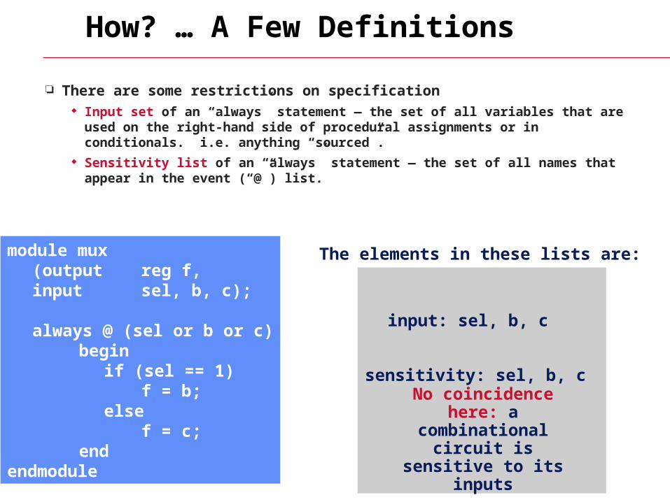
How? … A Few Definitions
There are some restrictions on specification Input set of an “always” statement — the set of all variables that are used on the
right-hand side of procedural assignments or in conditionals. i.e. anything “sourced”.
Sensitivity list of an “always” statement — the set of all names that appear in the event (“@”) list.
The elements in these lists are:module mux(output reg f,input sel, b, c);
always @ (sel or b or c)begin
if (sel == 1)f = b;
elsef = c;
endendmodule
input: sel, b, c
sensitivity: sel, b, c
No coincidence here: a combinational circuit is sensitive to its inputs

More Definitions...
… A control path of an “always” statement — a sequence of
operations performed when executing the always statement Combinational output of an “always” statement — a variable (or
variables) assigned to in every control path
What are they here...module mux(output reg f,input sel, b, c);
always @ (sel or b or c)begin
if (sel == 1)f = b;
elsef = c;
endendmodule
Control paths: through “then” and “else” of if statement
Combinational output: f
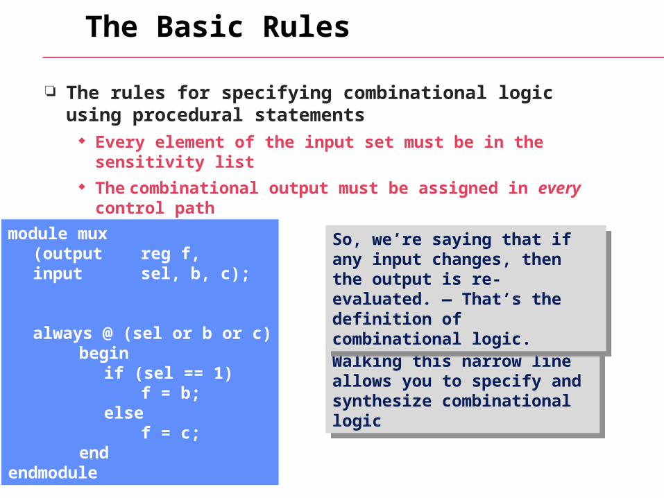
The Basic Rules
The rules for specifying combinational logic using procedural statements
Every element of the input set must be in the sensitivity list The combinational output must be assigned in every control path
Walking this narrow line allows you to specify and synthesize combinational logic
Walking this narrow line allows you to specify and synthesize combinational logic
So, we’re saying that if any input changes, then the output is re-evaluated. — That’s the definition of combinational logic.
So, we’re saying that if any input changes, then the output is re-evaluated. — That’s the definition of combinational logic.
module mux(output reg f,input sel, b, c);
always @ (sel or b or c)begin
if (sel == 1)f = b;
elsef = c;
endendmodule
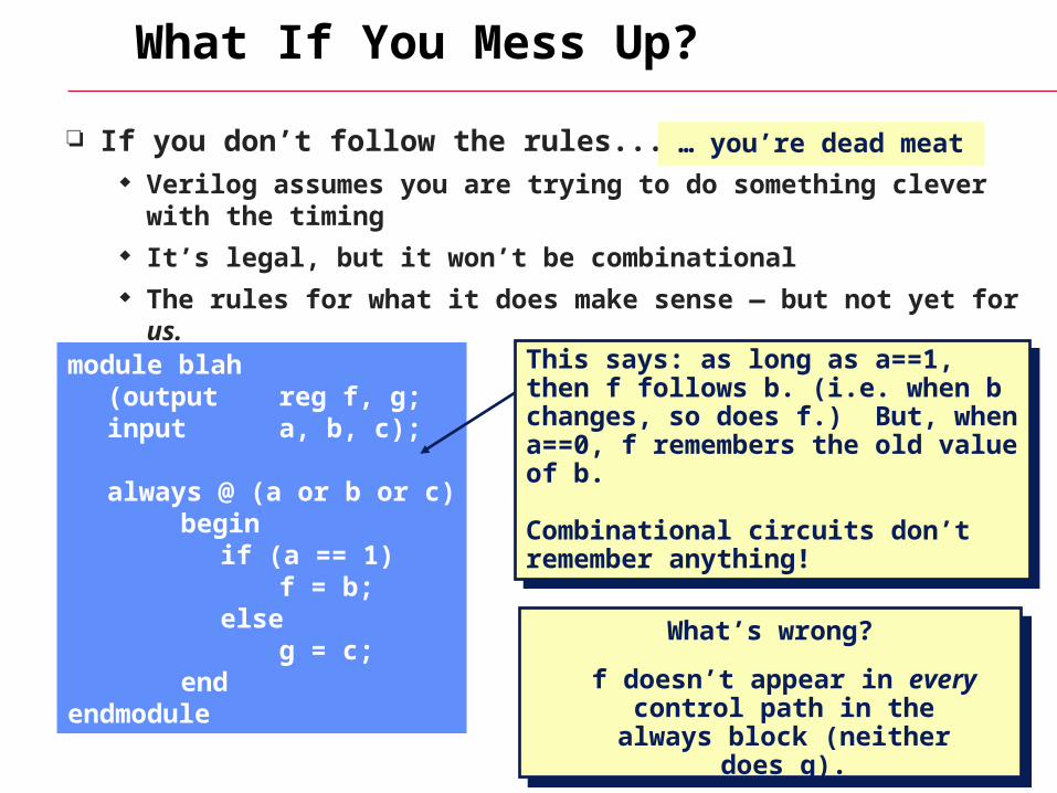
What If You Mess Up?
If you don’t follow the rules...? Verilog assumes you are trying to do something clever with the timing It’s legal, but it won’t be combinational The rules for what it does make sense — but not yet for us.
module blah (output reg f, g;input a, b, c);
always @ (a or b or c)begin
if (a == 1)f = b;
elseg = c;
endendmodule
What’s wrong?What’s wrong?
This says: as long as a==1, then f follows b. (i.e. when b changes, so does f.) But, when a==0, f remembers the old value of b.
Combinational circuits don’t remember anything!
This says: as long as a==1, then f follows b. (i.e. when b changes, so does f.) But, when a==0, f remembers the old value of b.
Combinational circuits don’t remember anything!
… you’re dead meat
f doesn’t appear in every control path in the always
block (neither does g).
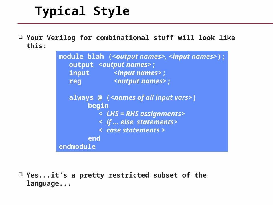
Typical Style
Your Verilog for combinational stuff will look like this:
Yes...it’s a pretty restricted subset of the language...
module blah (<output names>, <input names>);output <output names>;input <input names>;reg <output names>;
always @ (<names of all input vars>)begin
< LHS = RHS assignments>< if ... else statements>< case statements >
endendmodule
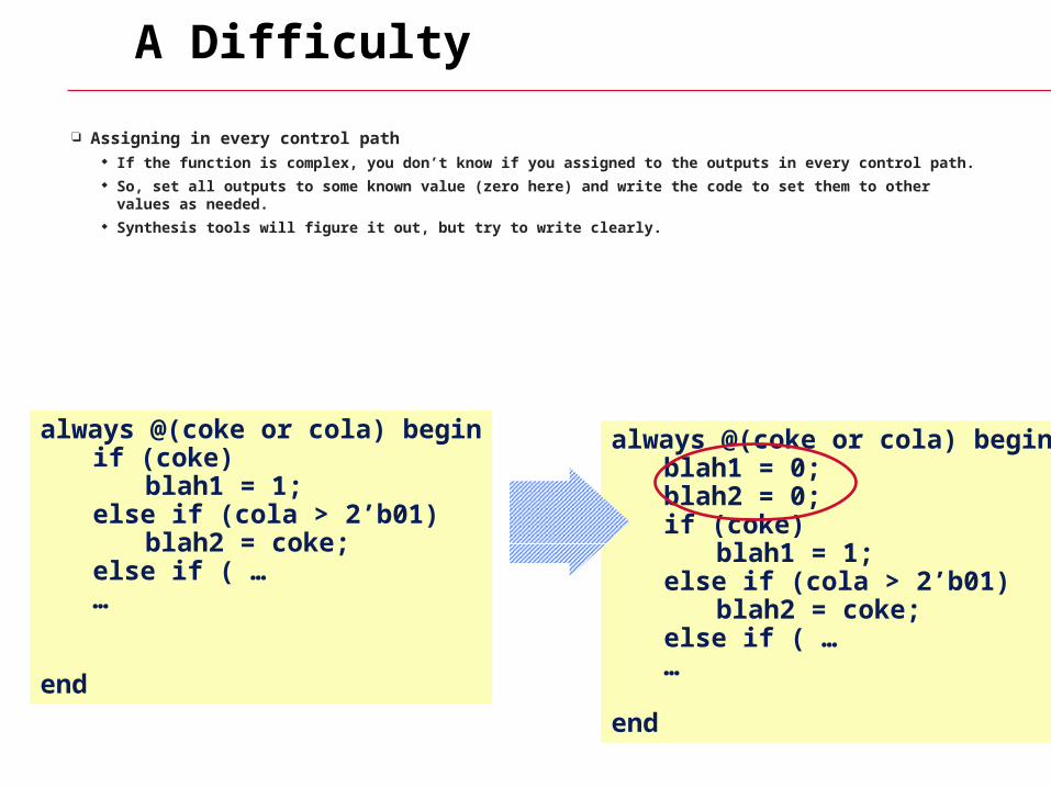
A Difficulty
Assigning in every control path If the function is complex, you don’t know if you assigned to the outputs in every control path. So, set all outputs to some known value (zero here) and write the code to set them to other values as
needed. Synthesis tools will figure it out, but try to write clearly.
always @(coke or cola) beginblah1 = 0;blah2 = 0;if (coke)
blah1 = 1;else if (cola > 2’b01)
blah2 = coke;else if ( ……
end
always @(coke or cola) beginif (coke)
blah1 = 1;else if (cola > 2’b01)
blah2 = coke;else if ( ……
end
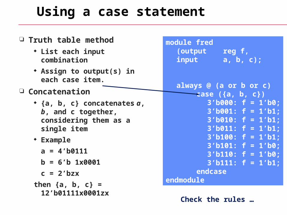
Using a case statement
Truth table method List each input combination Assign to output(s) in each
case item.
Concatenation {a, b, c} concatenates a, b, and
c together, considering them as a single item
Example
a = 4’b0111
b = 6’b 1x0001
c = 2’bzx
then {a, b, c} = 12’b01111x0001zx
module fred(output reg f,input a, b, c);
always @ (a or b or c)case ({a, b, c})
3’b000: f = 1’b0;3’b001: f = 1’b1;3’b010: f = 1’b1;3’b011: f = 1’b1;3’b100: f = 1’b1;3’b101: f = 1’b0;3’b110: f = 1’b0;3’b111: f = 1’b1;
endcaseendmodule
Check the rules …
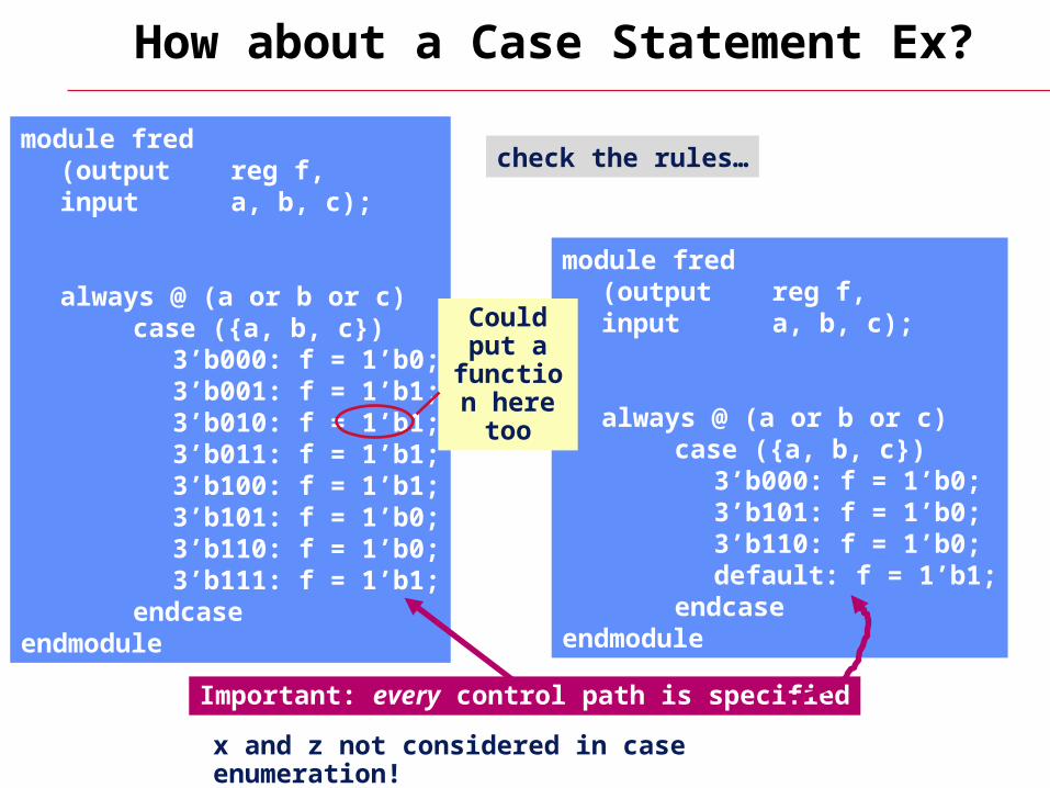
How about a Case Statement Ex?
module fred(output reg f,input a, b, c);
always @ (a or b or c)case ({a, b, c})
3’b000: f = 1’b0;3’b001: f = 1’b1;3’b010: f = 1’b1;3’b011: f = 1’b1;3’b100: f = 1’b1;3’b101: f = 1’b0;3’b110: f = 1’b0;3’b111: f = 1’b1;
endcaseendmodule
module fred(output reg f,input a, b, c);
always @ (a or b or c)case ({a, b, c})
3’b000: f = 1’b0;3’b101: f = 1’b0;3’b110: f = 1’b0;default: f = 1’b1;
endcaseendmodule
check the rules…
Important: every control path is specified
Could put a
function here too
x and z not considered in case enumeration!
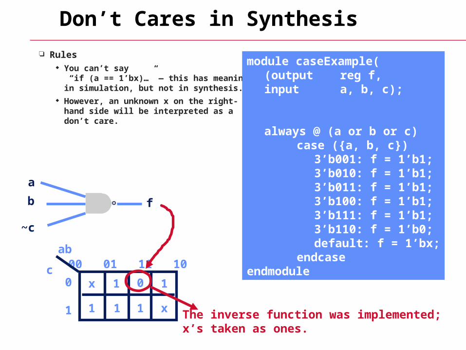
Don’t Cares in Synthesis
Rules You can’t say
“if (a == 1’bx)…” — this has meaning in simulation, but not in synthesis.
However, an unknown x on the right-hand side will be interpreted as a don’t care.
module caseExample((output reg f,input a, b, c);
always @ (a or b or c)case ({a, b, c})
3’b001: f = 1’b1;3’b010: f = 1’b1;3’b011: f = 1’b1;3’b100: f = 1’b1;3’b111: f = 1’b1;3’b110: f = 1’b0;default: f = 1’bx;
endcaseendmodule
a
b
~c
f
00 01 11 10
0
1
ab
c1 1
11 1
0x
x The inverse function was implemented;x’s taken as ones.
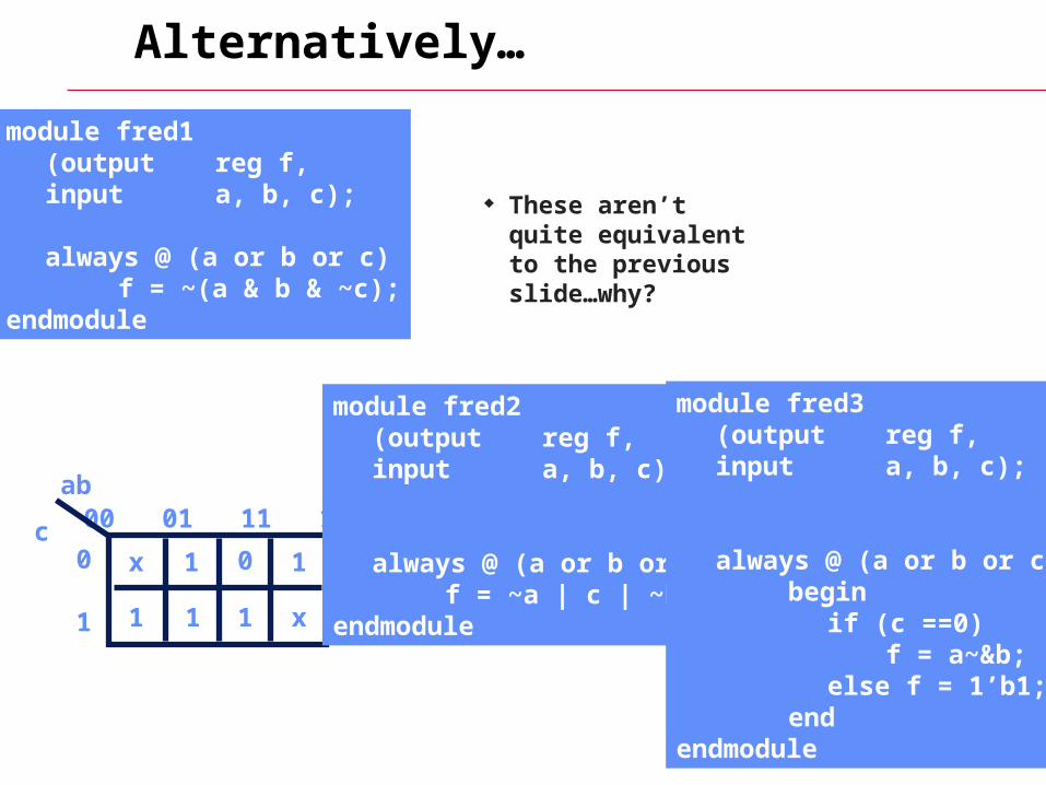
Alternatively…
These aren’t quite equivalent to the previous slide…why?
00 01 11 10
0
1
ab
c1 1
11 1
0x
x
module fred1 (output reg f,input a, b, c);
always @ (a or b or c)f = ~(a & b & ~c);
endmodule
module fred2 (output reg f,input a, b, c);
always @ (a or b or c)f = ~a | c | ~b;
endmodule
module fred3 (output reg f,input a, b, c);
always @ (a or b or c)begin
if (c ==0)f = a~&b;
else f = 1’b1;end
endmodule
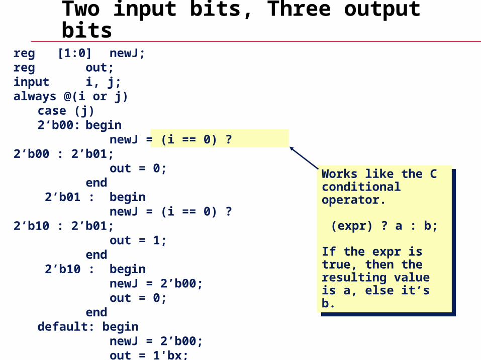
Two input bits, Three output bits
reg [1:0] newJ;reg out;input i, j;always @(i or j)
case (j)2’b00: begin
newJ = (i == 0) ? 2’b00 : 2’b01;out = 0;
end 2’b01 : begin
newJ = (i == 0) ? 2’b10 : 2’b01;out = 1;
end 2’b10 : begin
newJ = 2’b00;out = 0;
enddefault: begin
newJ = 2’b00;out = 1'bx;
endendcase
Works like the C conditional operator.
(expr) ? a : b;
If the expr is true, then the resulting value is a, else it’s b.
Works like the C conditional operator.
(expr) ? a : b;
If the expr is true, then the resulting value is a, else it’s b.
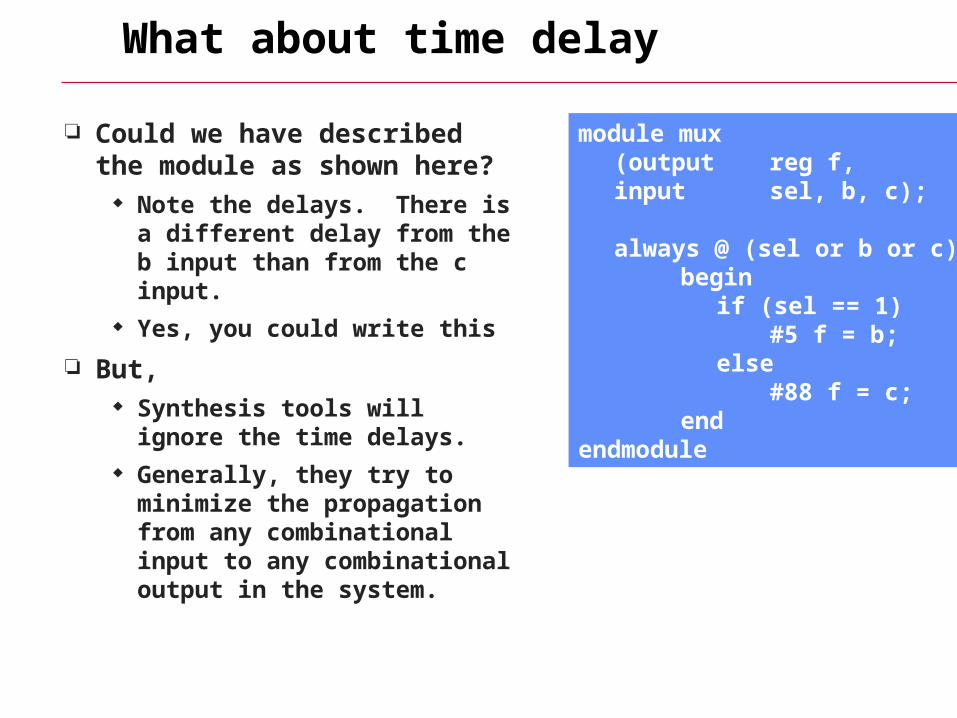
What about time delay
Could we have described the module as shown here?
Note the delays. There is a different delay from the b input than from the c input.
Yes, you could write this
But, Synthesis tools will ignore the
time delays. Generally, they try to minimize
the propagation from any combinational input to any combinational output in the system.
module mux(output reg f,input sel, b, c);
always @ (sel or b or c)begin
if (sel == 1)#5 f = b;
else#88 f = c;
endendmodule
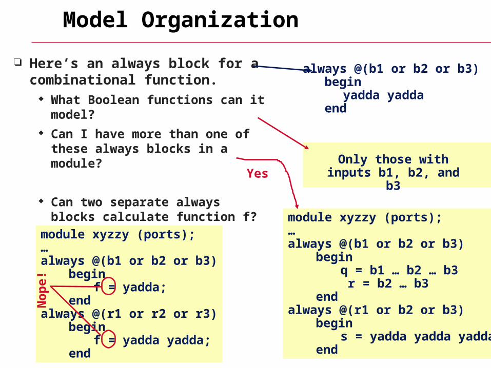
Model Organization
Here’s an always block for a combinational function.
What Boolean functions can it model? Can I have more than one of these
always blocks in a module?
Can two separate always blocks
calculate function f?
No
always @(b1 or b2 or b3)begin
yadda yaddaend
Only those with inputs b1, b2, and b3
module xyzzy (ports);…always @(b1 or b2 or b3)
beginq = b1 … b2 … b3 r = b2 … b3
endalways @(r1 or b2 or b3)
begins = yadda yadda yadda
end
module xyzzy (ports);…always @(b1 or b2 or b3)
beginf = yadda;
endalways @(r1 or r2 or r3)
beginf = yadda yadda;
end
No
pe!
Yes
FSM — Review
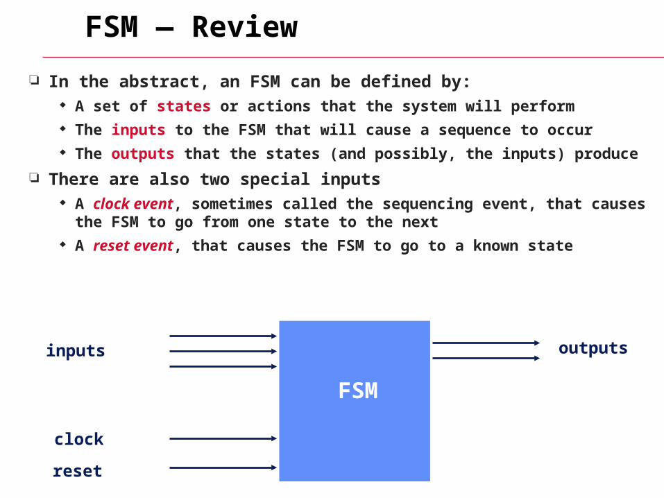
In the abstract, an FSM can be defined by: A set of states or actions that the system will perform The inputs to the FSM that will cause a sequence to occur The outputs that the states (and possibly, the inputs) produce
There are also two special inputs A clock event, sometimes called the sequencing event, that causes the
FSM to go from one state to the next A reset event, that causes the FSM to go to a known state
inputs outputs
clock
reset
FSM
FSM Review
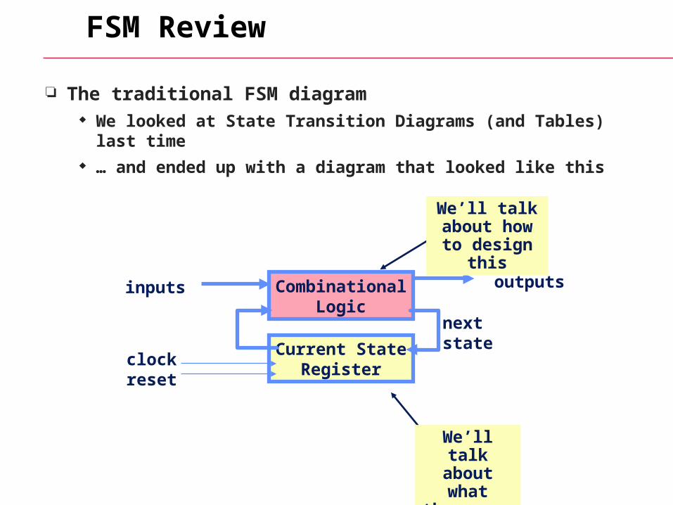
The traditional FSM diagram We looked at State Transition Diagrams (and Tables) last time … and ended up with a diagram that looked like this
CombinationalLogic
Current StateRegister
inputs outputs
clockreset
nextstate
We’ll talk about what these are
We’ll talk about how to design this

D Flip Flops
Edge triggered FF symbol
QD
Cclock Q and Q’
reset asserted low
data
What are they? A one-bit storage devices, sometimes
called a sequential element It “flip flops” between two states.
What are the ports? D is the data input — the value to be
remembered C is the clock input. The triangle
indicates that it’s edge sensitive. Q is the output (and Q’ is its
complement) Reset makes Q equal to zero anytime
reset is asserted (some “preset” to one also)
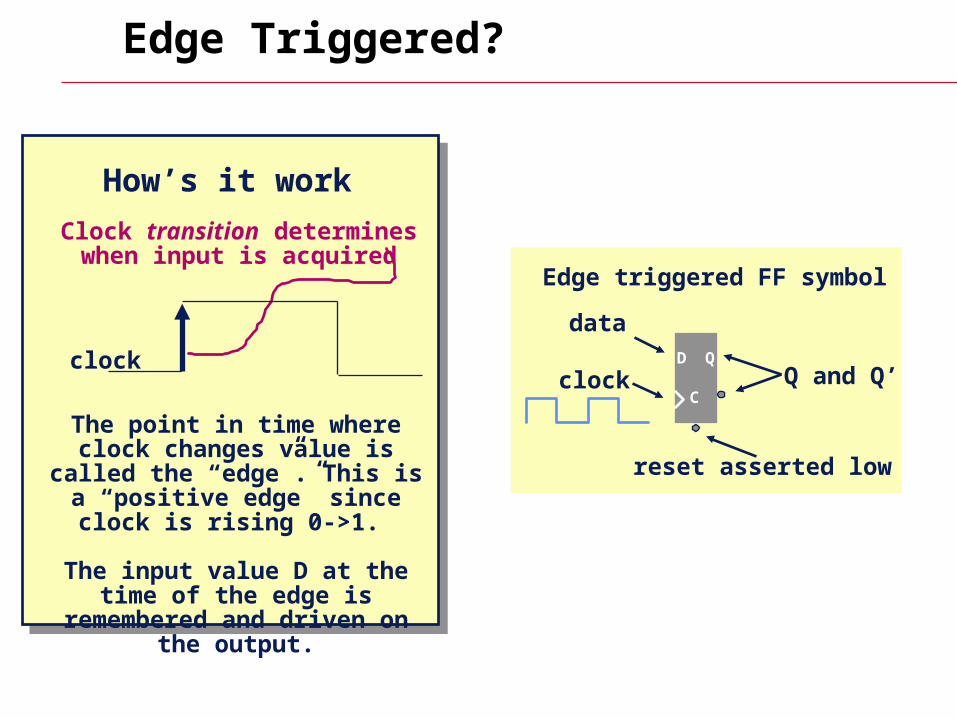
Edge Triggered?
Clock transition determineswhen input is acquired
The point in time where clock changes value is called the
“edge”. This is a “positive edge” since clock is rising 0->1.
The input value D at the time of the edge is remembered and
driven on the output.
clock
How’s it work
Edge triggered FF symbol
QD
Cclock Q and Q’
reset asserted low
data
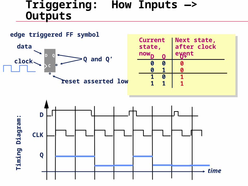
Triggering: How Inputs —> Outputs
edge triggered FF symbol
Tim
ing
Dia
gra
m: D
CLK
Q
D0011
Q0101
Q+
Current state, now
Next state, after clock event
time
QD
Cclock Q and Q’
reset asserted low
data
0011
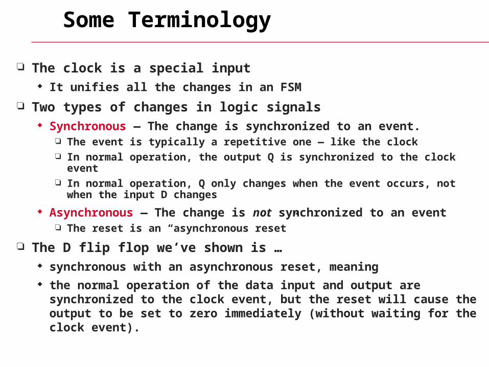
Some Terminology
The clock is a special input It unifies all the changes in an FSM
Two types of changes in logic signals Synchronous — The change is synchronized to an event.
The event is typically a repetitive one — like the clock In normal operation, the output Q is synchronized to the clock event In normal operation, Q only changes when the event occurs, not when the input
D changes
Asynchronous — The change is not synchronized to an event The reset is an “asynchronous reset”
The D flip flop we’ve shown is … synchronous with an asynchronous reset, meaning the normal operation of the data input and output are synchronized to the
clock event, but the reset will cause the output to be set to zero immediately (without waiting for the clock event).
Verilog for the D Flip FLop
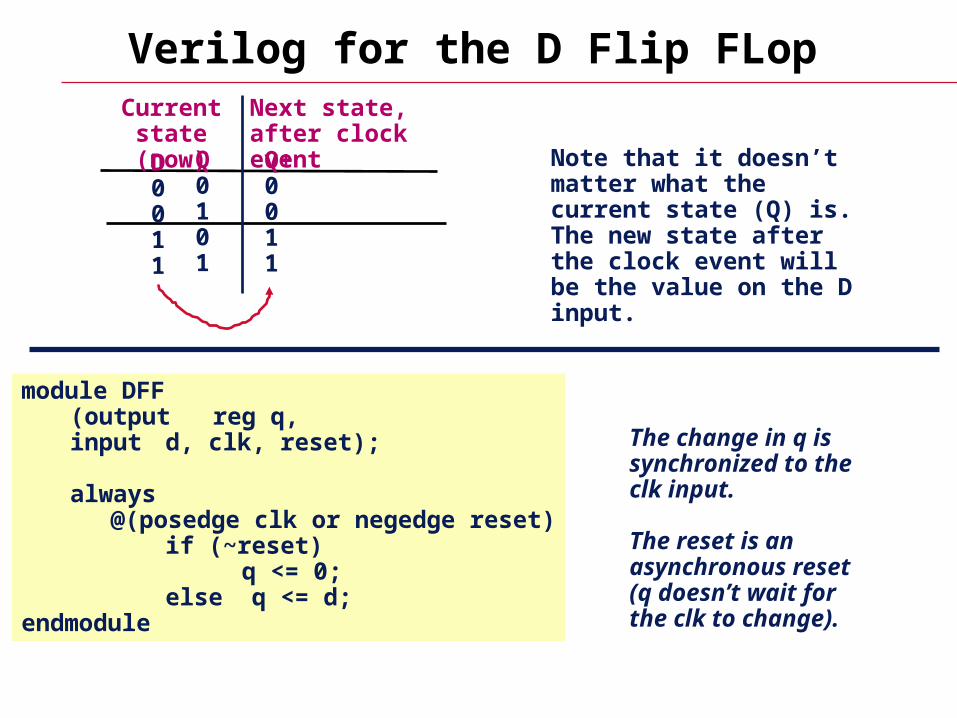
module DFF(output reg q,input d, clk, reset);
always@(posedge clk or negedge reset)
if (~reset) q <= 0;
else q <= d;endmodule
The change in q is synchronized to the clk input.
The reset is an asynchronous reset (q doesn’t wait for the clk to change).
Note that it doesn’t matter what the current state (Q) is. The new state after the clock event will be the value on the D input.
D0011
Q0101
Q+0011
Current state (now)
Next state, after clock event
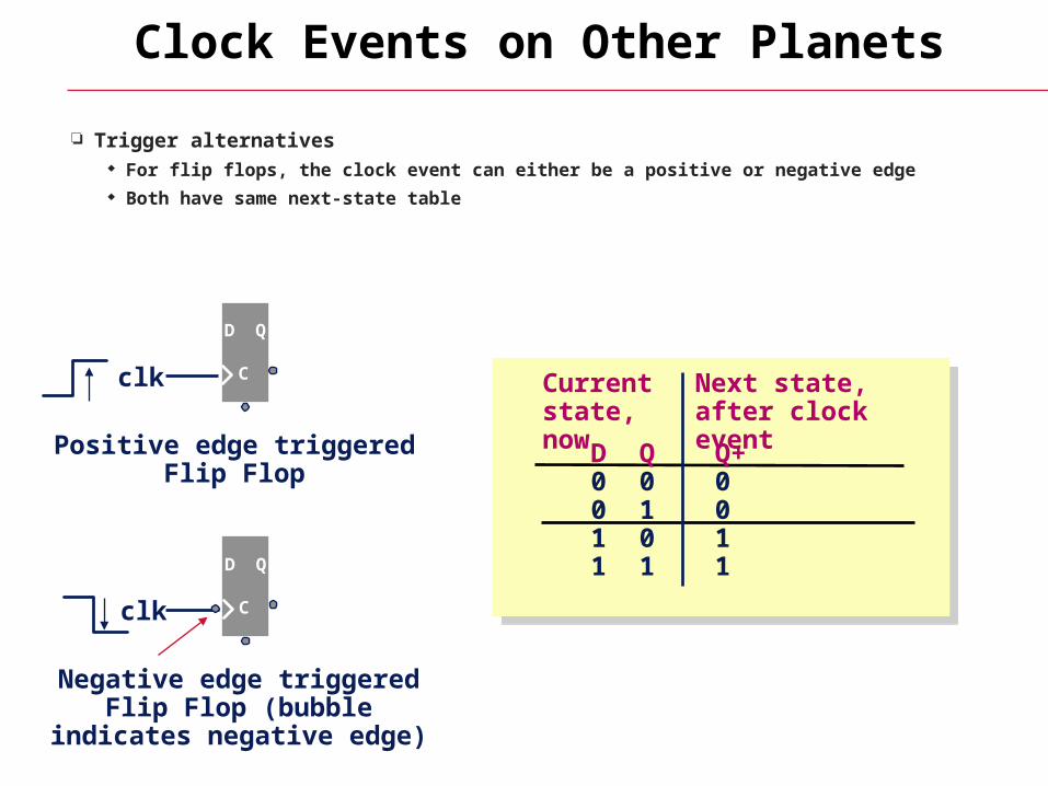
Clock Events on Other Planets
Trigger alternatives For flip flops, the clock event can either be a positive or negative edge Both have same next-state table
clk
Positive edge triggeredFlip Flop
QD
C
Negative edge triggered Flip Flop (bubble indicates
negative edge)
clk
QD
C
D0011
Q0101
Q+0011
Current state, now
Next state, after clock event

Where Are Flip Flops in FSMs?
Current State Register Each bit of the register is implemented with a flip flop The clocks of all flip flops are tied together into one clock line The reset (or preset) of all flip flops are tied together into one reset line
CombinationalLogic
Current StateRegister
inputs outputs
clockreset
nextstate
We’ll talk about how to design this
There
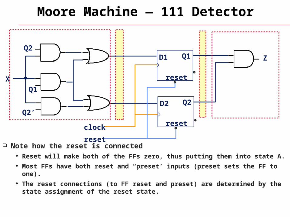
Moore Machine — 111 Detector
Note how the reset is connected Reset will make both of the FFs zero, thus putting them into state A. Most FFs have both reset and “preset’ inputs (preset sets the FF to one). The reset connections (to FF reset and preset) are determined by the state
assignment of the reset state.
X
Q2
Q1
Q2’
D1 Q1
D2 Q2
Z
clock
reset
reset
reset
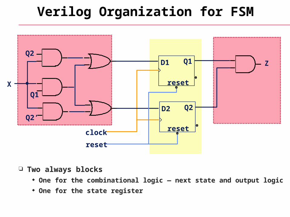
Verilog Organization for FSM
Two always blocks One for the combinational logic — next state and output logic One for the state register
X
Q2
Q1
Q2’
D1 Q1
D2 Q2
Z
clock
reset
reset
reset
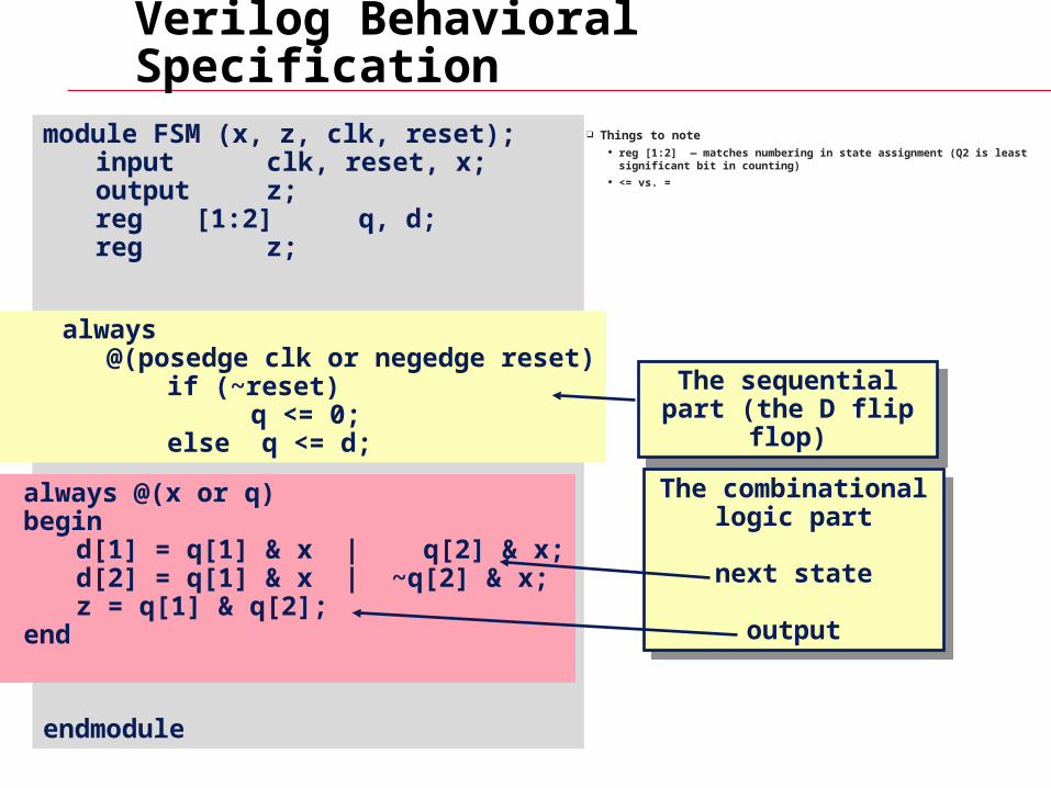
module FSM (x, z, clk, reset);input clk, reset, x;output z;reg [1:2] q, d;reg z;
endmodule
Verilog Behavioral Specification
Things to note reg [1:2] — matches numbering in state assignment (Q2 is least significant bit
in counting) <= vs. =
always @(x or q)begin
d[1] = q[1] & x | q[2] & x;d[2] = q[1] & x | ~q[2] & x;z = q[1] & q[2];
end
always@(posedge clk or negedge reset)
if (~reset) q <= 0;
else q <= d;
The sequential part (the D flip flop)
The sequential part (the D flip flop)
The combinational logic part
next state
output
The combinational logic part
next state
output
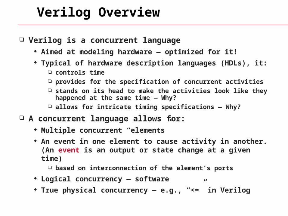
Verilog Overview
Verilog is a concurrent language Aimed at modeling hardware — optimized for it! Typical of hardware description languages (HDLs), it:
controls time provides for the specification of concurrent activities stands on its head to make the activities look like they happened at
the same time — Why? allows for intricate timing specifications — Why?
A concurrent language allows for: Multiple concurrent “elements” An event in one element to cause activity in another. (An event is
an output or state change at a given time) based on interconnection of the element’s ports
Logical concurrency — software True physical concurrency — e.g., “<=” in Verilog
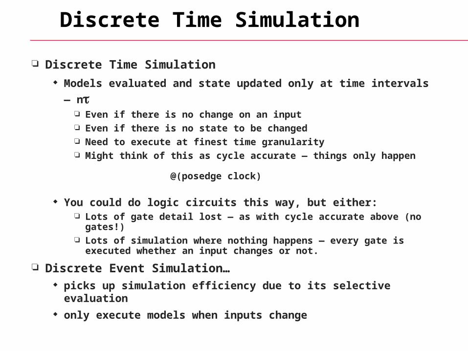
Discrete Time Simulation
Discrete Time Simulation
Models evaluated and state updated only at time intervals — n Even if there is no change on an input Even if there is no state to be changed Need to execute at finest time granularity Might think of this as cycle accurate — things only happen
@(posedge clock)
You could do logic circuits this way, but either: Lots of gate detail lost — as with cycle accurate above (no gates!) Lots of simulation where nothing happens — every gate is executed
whether an input changes or not.
Discrete Event Simulation… picks up simulation efficiency due to its selective evaluation only execute models when inputs change
Discrete Event (DE) Simulation
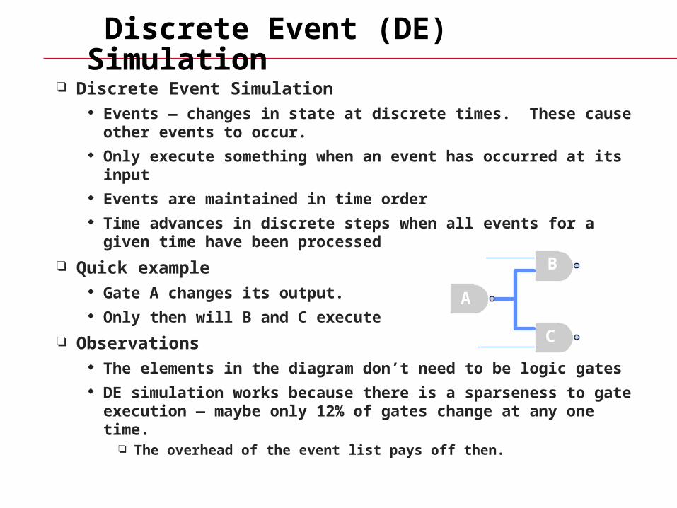
Discrete Event Simulation Events — changes in state at discrete times. These cause other
events to occur. Only execute something when an event has occurred at its input Events are maintained in time order Time advances in discrete steps when all events for a given time
have been processed
Quick example Gate A changes its output. Only then will B and C execute
Observations The elements in the diagram don’t need to be logic gates DE simulation works because there is a sparseness to gate
execution — maybe only 12% of gates change at any one time. The overhead of the event list pays off then.
A
B
C
Observations
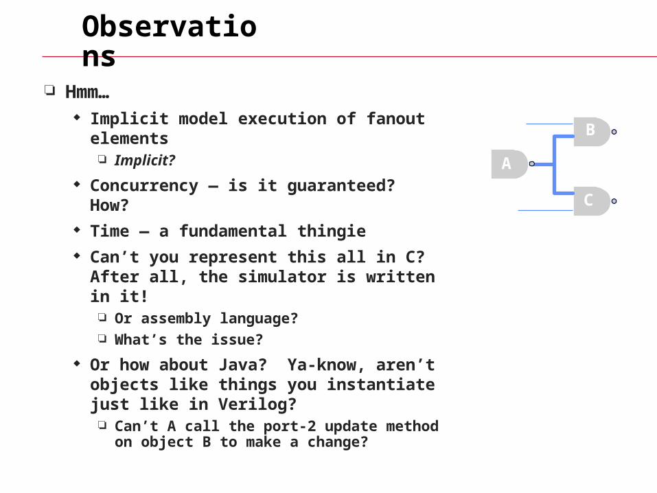
Hmm… Implicit model execution of fanout elements
Implicit?
Concurrency — is it guaranteed? How? Time — a fundamental thingie Can’t you represent this all in C? After all,
the simulator is written in it! Or assembly language? What’s the issue?
Or how about Java? Ya-know, aren’t objects like things you instantiate just like in Verilog? Can’t A call the port-2 update method on
object B to make a change?
A
B
C
A Gate Level Model
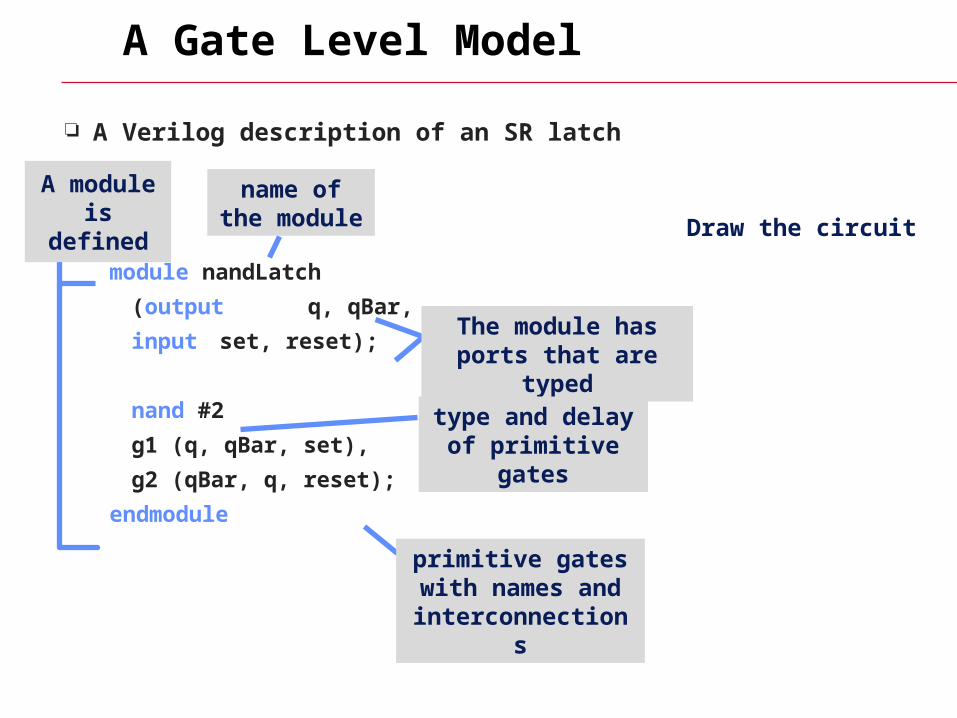
A Verilog description of an SR latch
module nandLatch
(output q, qBar,
input set, reset);
nand #2
g1 (q, qBar, set),
g2 (qBar, q, reset);
endmodule
A module is defined
name of the module
The module has ports that are typed
primitive gates with names and
interconnections
type and delay of primitive gates
Draw the circuit
A Gate Level Model
Things to note: It doesn’t appear “executable” — no for loops, if-then-else, etc.
it’s not in a programming language sense, rather it describes the interconnection of elements
A new module made up of other modules (gates) has been defined
software engineering aspect — we can hide detail
module nandLatch
(output q, qBar,
input set, rese)t;
nand #2
g1 (q, qBar, set),
g2 (qBar, q, reset);
endmodule

Kinds of delays
Transport delay input to output delay (sometimes “propagation”)
Zero delay models (all transport delays = 0) functional testing there’s no delay, not cool for circuits with feedback!
Unit delay models (all transport delays = 1) all gates have delay 1. OK for feedback
Edge sensitive — delay is value sensitive
ab c
— transport delay
nand #(3, 4, 5) (c, a, b);
rising delay
falling delay
delay to z
Some more gate level examples
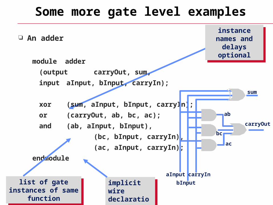
An adder
module adder
(output carryOut, sum,
input aInput, bInput, carryIn);
xor (sum, aInput, bInput, carryIn);
or (carryOut, ab, bc, ac);
and (ab, aInput, bInput),
(bc, bInput, carryIn),
(ac, aInput, carryIn);
endmodule
aInput
bInput
carryIn
carryOut
sum
list of gate instances of same function
list of gate instances of same function
instance names and delays
optional
instance names and delays
optional
implicit wire declarations
implicit wire declarations
ab
bc
ac
Adder with delays
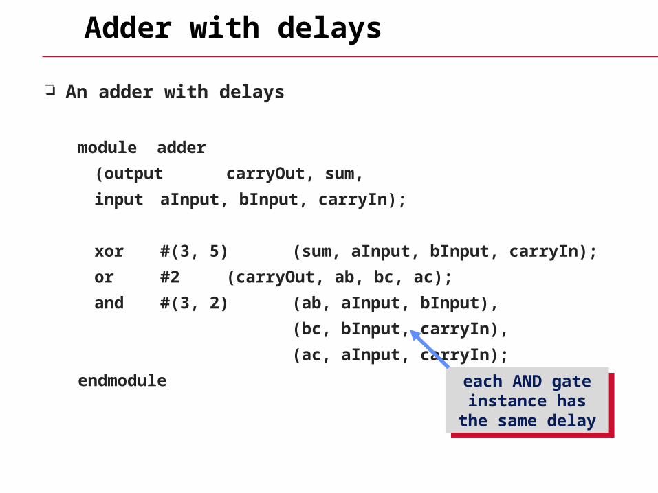
An adder with delays
module adder
(output carryOut, sum,
input aInput, bInput, carryIn);
xor #(3, 5) (sum, aInput, bInput, carryIn);
or #2 (carryOut, ab, bc, ac);
and #(3, 2) (ab, aInput, bInput),
(bc, bInput, carryIn),
(ac, aInput, carryIn);
endmodule each AND gate instance has the
same delay
each AND gate instance has the
same delay
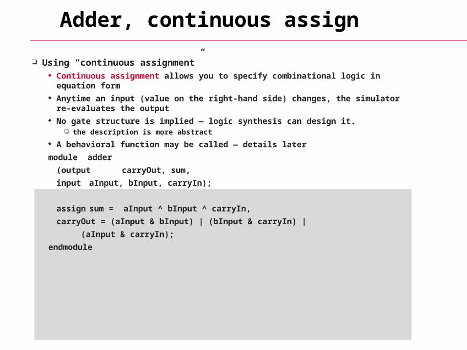
Adder, continuous assign
Using “continuous assignment” Continuous assignment allows you to specify combinational logic in equation form Anytime an input (value on the right-hand side) changes, the simulator re-evaluates
the output No gate structure is implied — logic synthesis can design it.
the description is more abstract
A behavioral function may be called — details later
module adder
(output carryOut, sum,
input aInput, bInput, carryIn);
assign sum = aInput ^ bInput ^ carryIn,
carryOut = (aInput & bInput) | (bInput & carryIn) |
(aInput & carryIn);
endmodule
I’m sick of this adder
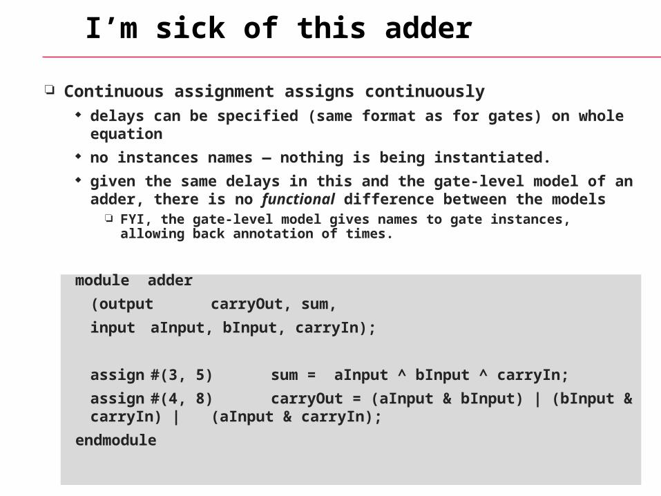
Continuous assignment assigns continuously delays can be specified (same format as for gates) on whole equation no instances names — nothing is being instantiated. given the same delays in this and the gate-level model of an adder,
there is no functional difference between the models FYI, the gate-level model gives names to gate instances, allowing back
annotation of times.
module adder
(output carryOut, sum,
input aInput, bInput, carryIn);
assign #(3, 5) sum = aInput ^ bInput ^ carryIn;
assign #(4, 8) carryOut = (aInput & bInput) | (bInput & carryIn) | (aInput & carryIn);
endmodule
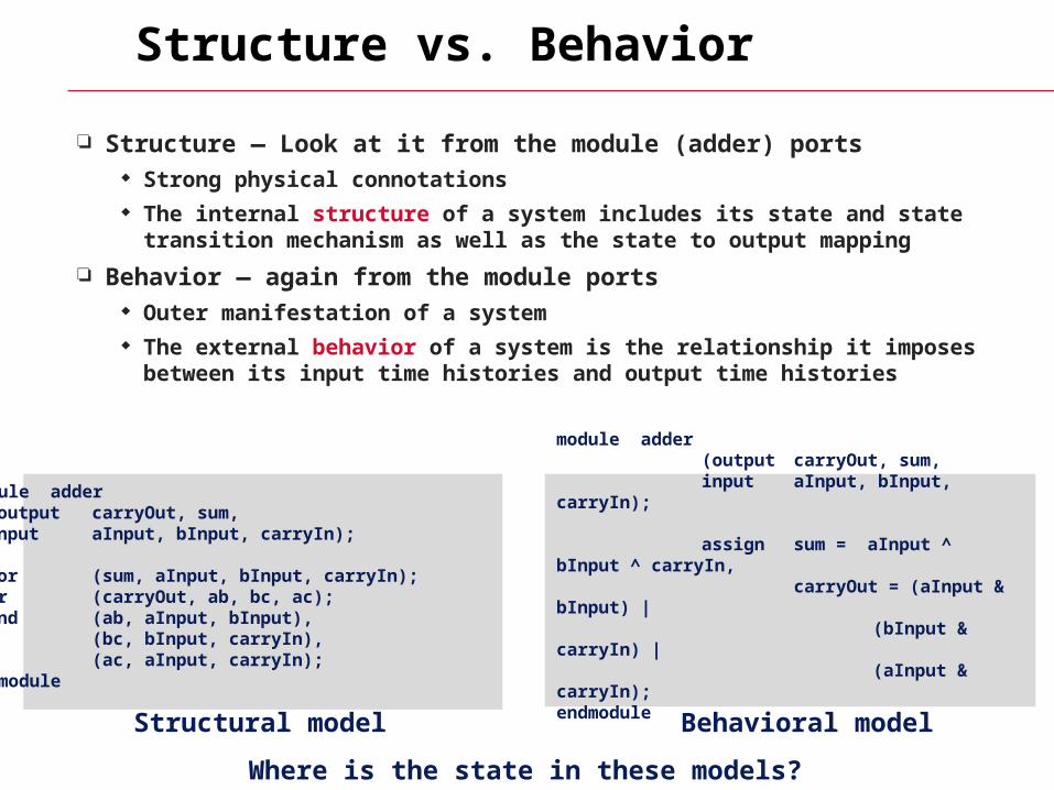
Structure vs. Behavior
Structure — Look at it from the module (adder) ports Strong physical connotations The internal structure of a system includes its state and state
transition mechanism as well as the state to output mapping
Behavior — again from the module ports Outer manifestation of a system The external behavior of a system is the relationship it imposes
between its input time histories and output time histories
Where is the state in these models?
Structural model Behavioral model
module adder (output carryOut, sum, input aInput, bInput, carryIn);
assign sum = aInput ^ bInput ^ carryIn, carryOut = (aInput & bInput) |
(bInput & carryIn) | (aInput & carryIn);endmodule
module adder (output carryOut, sum, input aInput, bInput, carryIn);
xor (sum, aInput, bInput, carryIn); or (carryOut, ab, bc, ac); and (ab, aInput, bInput), (bc, bInput, carryIn), (ac, aInput, carryIn);endmodule
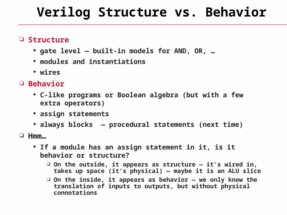
Verilog Structure vs. Behavior
Structure gate level — built-in models for AND, OR, … modules and instantiations wires
Behavior C-like programs or Boolean algebra (but with a few extra
operators) assign statements always blocks — procedural statements (next time)
Hmm… If a module has an assign statement in it, is it behavior or
structure? On the outside, it appears as structure — it’s wired in, takes up space
(it’s physical) — maybe it is an ALU slice On the inside, it appears as behavior — we only know the translation
of inputs to outputs, but without physical connotations
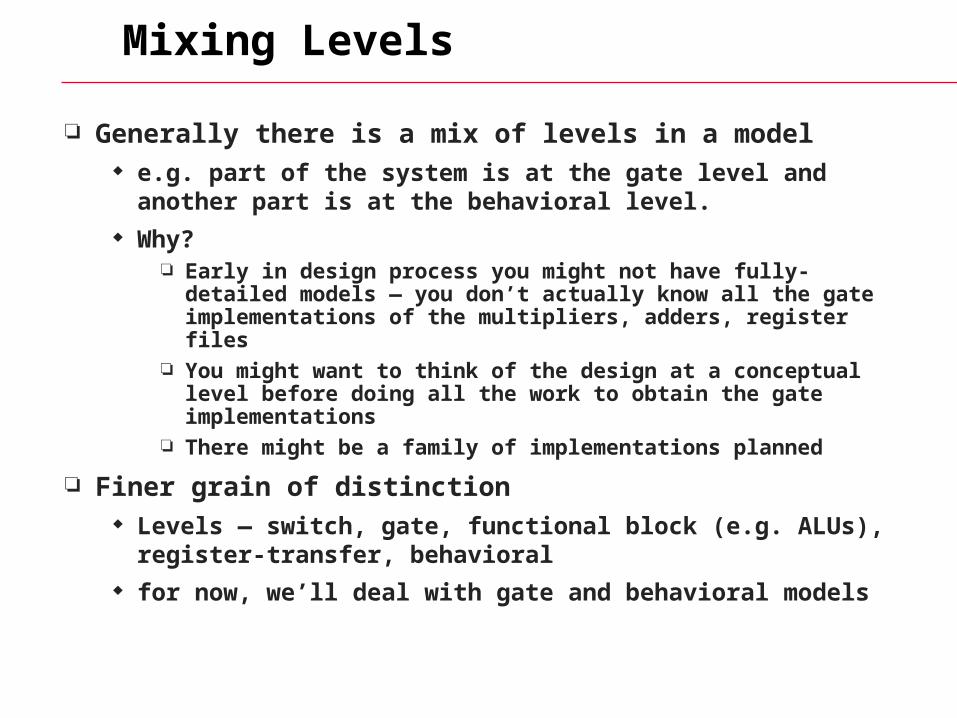
Mixing Levels
Generally there is a mix of levels in a model e.g. part of the system is at the gate level and another part is at
the behavioral level. Why?
Early in design process you might not have fully-detailed models — you don’t actually know all the gate implementations of the multipliers, adders, register files
You might want to think of the design at a conceptual level before doing all the work to obtain the gate implementations
There might be a family of implementations planned
Finer grain of distinction Levels — switch, gate, functional block (e.g. ALUs), register-
transfer, behavioral for now, we’ll deal with gate and behavioral models
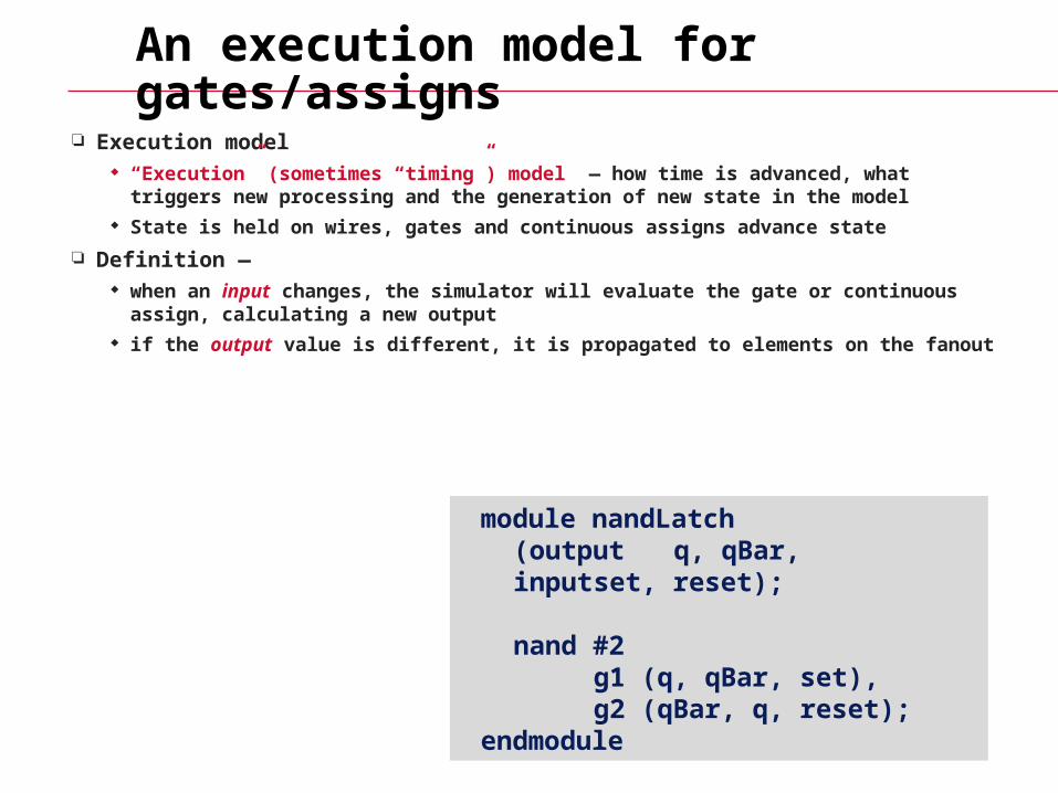
Execution model “Execution” (sometimes “timing”) model — how time is advanced, what triggers new
processing and the generation of new state in the model State is held on wires, gates and continuous assigns advance state
Definition — when an input changes, the simulator will evaluate the gate or continuous assign,
calculating a new output if the output value is different, it is propagated to elements on the fanout
An execution model for gates/assigns
module nandLatch (output q, qBar,
input set, reset); nand #2 g1 (q, qBar, set), g2 (qBar, q, reset);endmodule
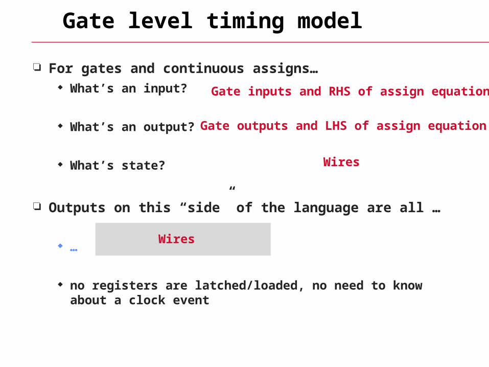
Gate level timing model
For gates and continuous assigns… What’s an input?
What’s an output?
What’s state?
Outputs on this “side” of the language are all …
…
no registers are latched/loaded, no need to know about a clock event
Wires
Gate inputs and RHS of assign equation
Gate outputs and LHS of assign equation
Wires
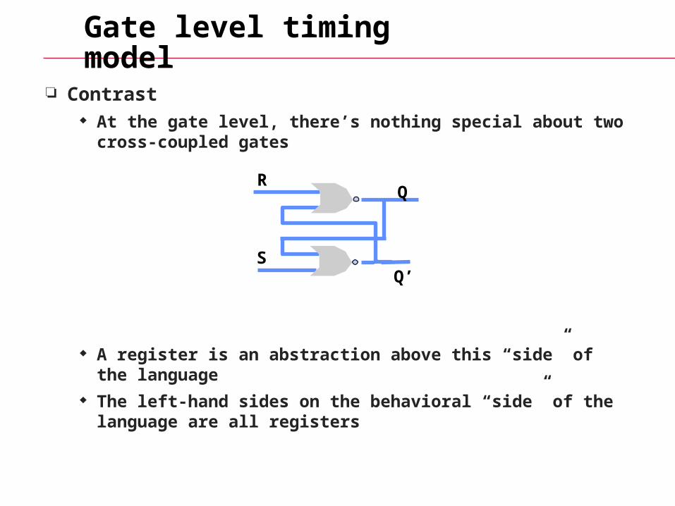
Gate level timing model
Contrast At the gate level, there’s nothing special about two cross-coupled
gates
A register is an abstraction above this “side” of the language The left-hand sides on the behavioral “side” of the language are
all registers
R
S
Q
Q’
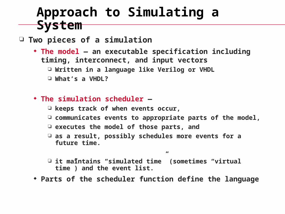
Approach to Simulating a System
Two pieces of a simulation The model — an executable specification including timing,
interconnect, and input vectors Written in a language like Verilog or VHDL What’s a VHDL?
The simulation scheduler — keeps track of when events occur, communicates events to appropriate parts of the model, executes the model of those parts, and as a result, possibly schedules more events for a future time.
it maintains “simulated time” (sometimes “virtual time”) and the event list.
Parts of the scheduler function define the language
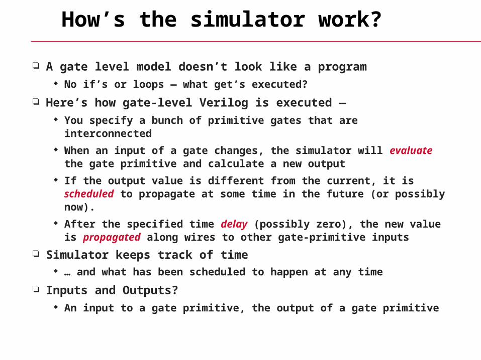
How’s the simulator work?
A gate level model doesn’t look like a program No if’s or loops — what get’s executed?
Here’s how gate-level Verilog is executed — You specify a bunch of primitive gates that are interconnected
When an input of a gate changes, the simulator will evaluate the gate primitive and calculate a new output
If the output value is different from the current, it is scheduled to propagate at some time in the future (or possibly now).
After the specified time delay (possibly zero), the new value is propagated along wires to other gate-primitive inputs
Simulator keeps track of time … and what has been scheduled to happen at any time
Inputs and Outputs? An input to a gate primitive, the output of a gate primitive
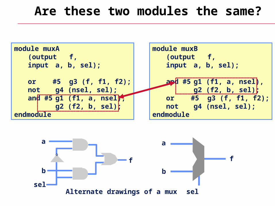
Are these two modules the same?
a
b
f
sel
a
b
sel
f
Alternate drawings of a mux
module muxB (output f, input a, b, sel);
and #5 g1 (f1, a, nsel),g2 (f2, b, sel);
or #5 g3 (f, f1, f2);not g4 (nsel, sel);
endmodule
module muxA (output f, input a, b, sel);
or #5 g3 (f, f1, f2);not g4 (nsel, sel);and #5 g1 (f1, a, nsel),
g2 (f2, b, sel);endmodule
Inside the Simulator
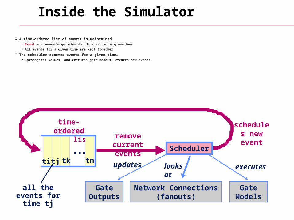
A time-ordered list of events is maintained Event — a value-change scheduled to occur at a given time All events for a given time are kept together
The scheduler removes events for a given time… …propagates values, and executes gate models, creates new events…
Scheduler
Gate Models
Network Connections (fanouts)
executeslooks at
schedules new eventremove current
events
time-ordered event list
Gate Outputs
updatesti tj tk•••
tn
all the events for time tj
Event-Driven Simulation
e
evaluate these
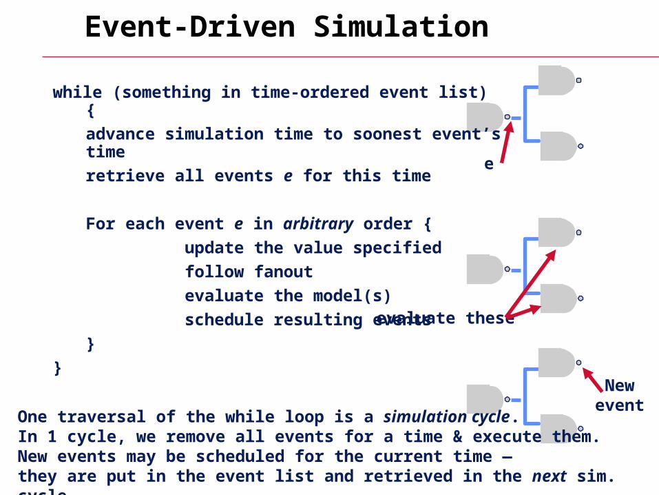
One traversal of the while loop is a simulation cycle. In 1 cycle, we remove all events for a time & execute them. New events may be scheduled for the current time — they are put in the event list and retrieved in the next sim. cycle.
while (something in time-ordered event list) {
advance simulation time to soonest event’s time
retrieve all events e for this time
For each event e in arbitrary order {
update the value specified
follow fanout
evaluate the model(s)
schedule resulting events
}
}
Newevent
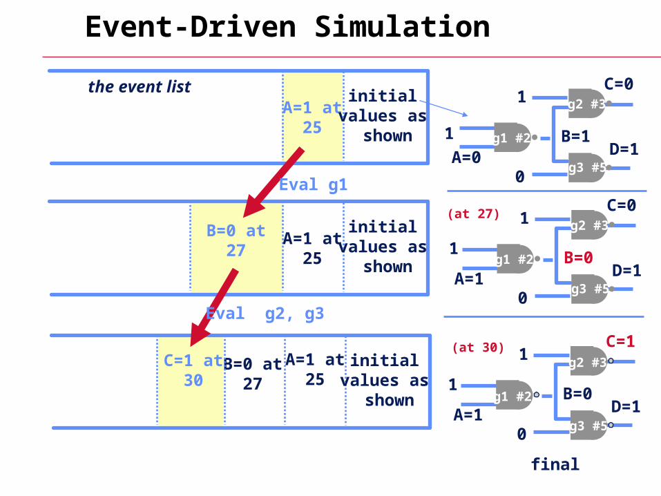
Event-Driven Simulation
A=1 at 25
g2 #3
g1 #2
g3 #5
1
1
0A=0
B=1
C=0
D=1
initial values as
shown
initial values as
shown
B=0 at27
A=1 at 25
C=1 at30
g2 #3
g1 #2
g3 #5
1
1
0A=1
B=0
C=0
D=1
the event list
(at 27)initial
values as shown
A=1 at 25
B=0 at27
g2 #3
g1 #2
g3 #5
1
1
0A=1
B=0
C=1
D=1
final
(at 30)
Eval g1
Eval g2, g3
event
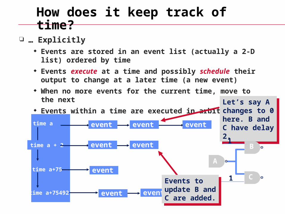
How does it keep track of time?
… Explicitly Events are stored in an event list (actually a 2-D list) ordered by
time Events execute at a time and possibly schedule their output to
change at a later time (a new event) When no more events for the current time, move to the next Events within a time are executed in arbitrary order
time a
time a+75
time a+75492
eventevent event
event
Let’s say A changes to 0 here. B and C have delay 2.
Let’s say A changes to 0 here. B and C have delay 2.
A
B
C
1
1
event
time a + 2 eventevent
Events to update B and C are added.
Events to update B and C are added.
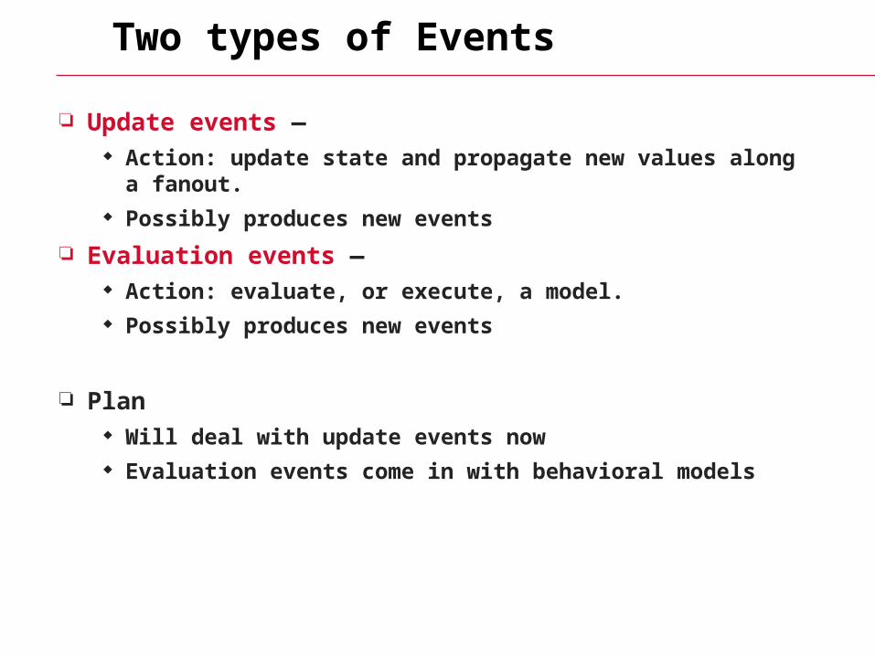
Two types of Events
Update events — Action: update state and propagate new values along a fanout. Possibly produces new events
Evaluation events — Action: evaluate, or execute, a model. Possibly produces new events
Plan Will deal with update events now Evaluation events come in with behavioral models
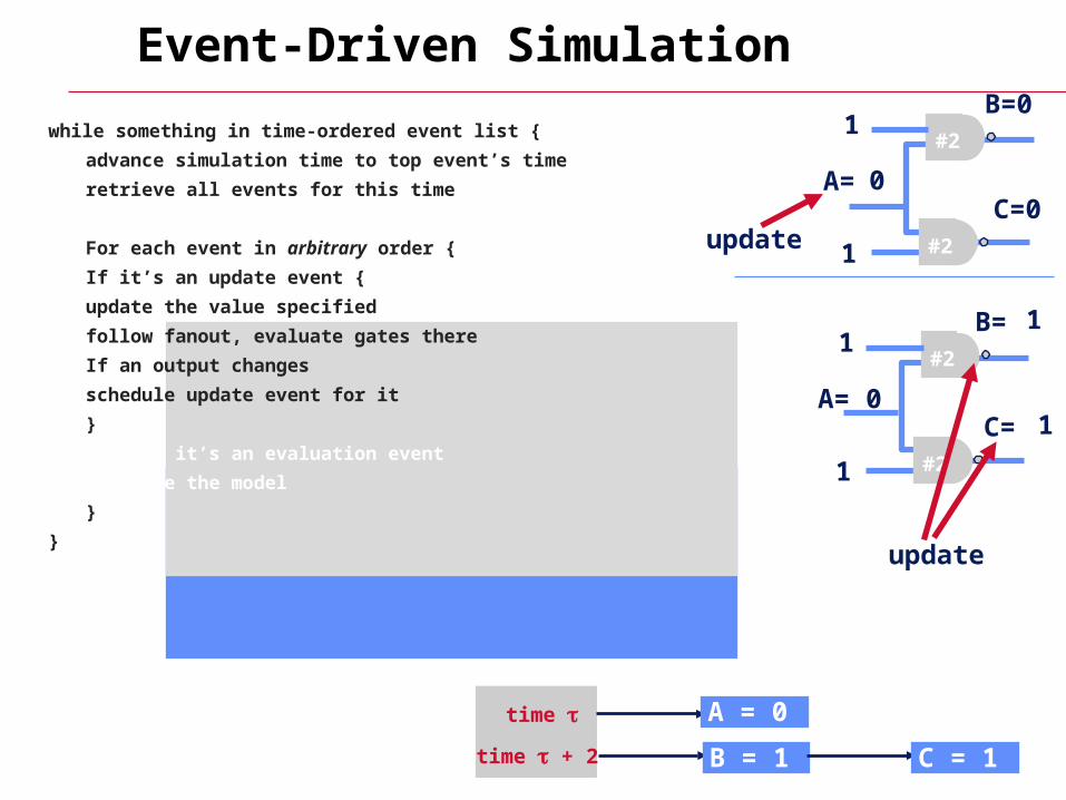
while something in time-ordered event list {
advance simulation time to top event’s time
retrieve all events for this time
For each event in arbitrary order {
If it’s an update event {
update the value specified
follow fanout, evaluate gates there
If an output changes
schedule update event for it
}
else // it’s an evaluation event
evaluate the model
}
}
Event-Driven Simulation
#21
1
A= 1
B=0
C=0#2
#21
1
A= 0
#2
time A = 0
update
0
B= 0
C= 0
B = 1 C = 1time + 2
update
1
1
while something in time-ordered event list {
advance simulation time to top event’s time
retrieve all events for this time
For each event in arbitrary order {
If it’s an update event {
update the value specified
follow fanout, evaluate gates there
If an output changes
schedule update event for it
}
else // it’s an evaluation event
evaluate the model
}
}
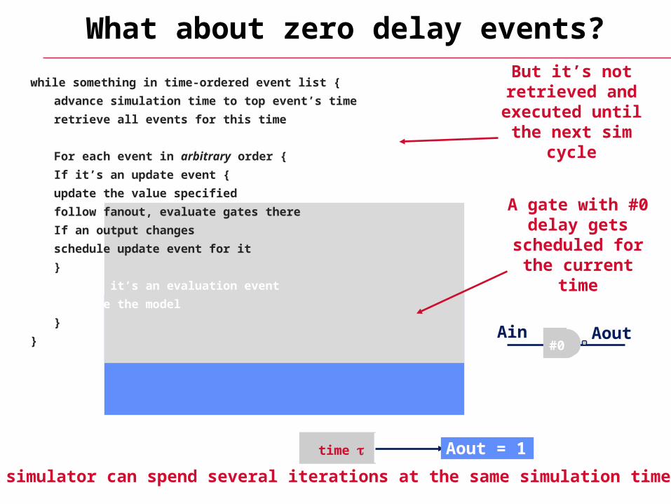
What about zero delay events?
A gate with #0 delay gets
scheduled for the current time
But it’s not retrieved and
executed until the next sim cycle
The simulator can spend several iterations at the same simulation time
time Ain = 0
#0Ain Aout
Aout = 1
Verilog Gate level timing model
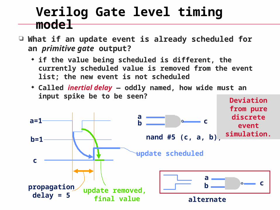
What if an update event is already scheduled for an primitive gate output? if the value being scheduled is different, the currently scheduled
value is removed from the event list; the new event is not scheduled
Called inertial delay — oddly named, how wide must an input spike be to be seen?
a=1
b=1
ab c
c
propagationdelay = 5
update scheduled
update removed, final value
nand #5 (c, a, b);
Deviation from pure discrete
event simulation.
ab c
alternate
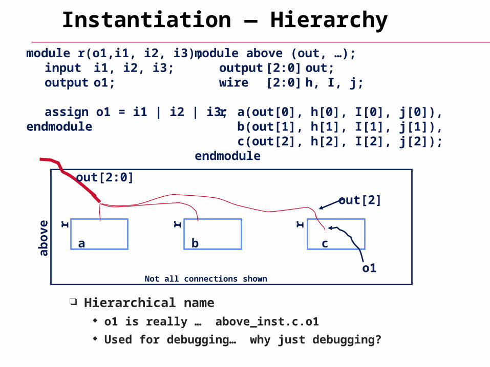
module r(o1,i1, i2, i3);input i1, i2, i3;output o1;
assign o1 = i1 | i2 | i3;endmodule
module above (out, …);output [2:0] out;wire [2:0] h, I, j;
r a(out[0], h[0], I[0], j[0]),b(out[1], h[1], I[1], j[1]),c(out[2], h[2], I[2], j[2]);
endmodule
out[2:0]
a b c
out[2]
o1
abo
ve
r r r
Instantiation — Hierarchy
Hierarchical name o1 is really … above_inst.c.o1 Used for debugging… why just debugging?
Not all connections shown
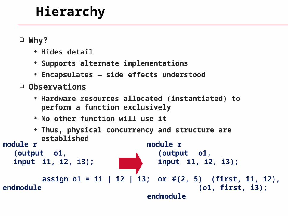
Hierarchy
Why? Hides detail Supports alternate implementations Encapsulates — side effects understood
Observations Hardware resources allocated (instantiated) to perform a function
exclusively No other function will use it Thus, physical concurrency and structure are established
module r(output o1,input i1, i2, i3);
assign o1 = i1 | i2 | i3;endmodule
module r(output o1,input i1, i2, i3);
or #(2, 5) (first, i1, i2),(o1, first, i3);
endmodule
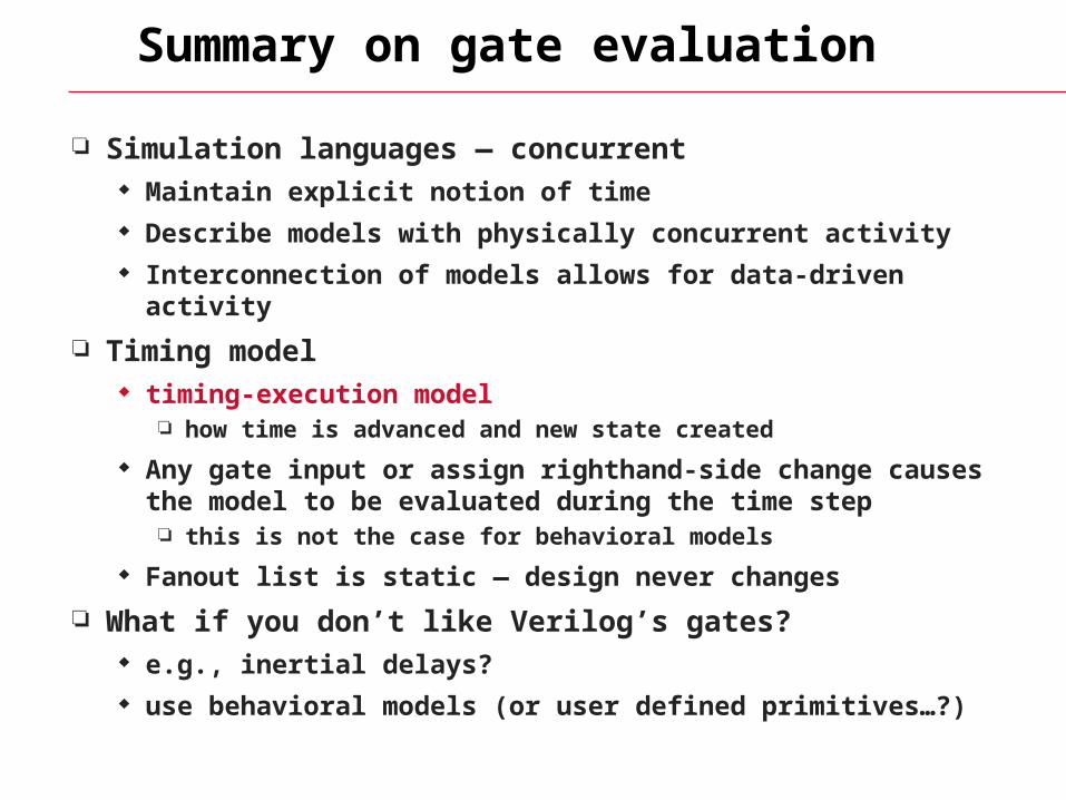
Summary on gate evaluation
Simulation languages — concurrent Maintain explicit notion of time Describe models with physically concurrent activity Interconnection of models allows for data-driven activity
Timing model timing-execution model
how time is advanced and new state created
Any gate input or assign righthand-side change causes the model to be evaluated during the time step this is not the case for behavioral models
Fanout list is static — design never changes
What if you don’t like Verilog’s gates? e.g., inertial delays? use behavioral models (or user defined primitives…?)
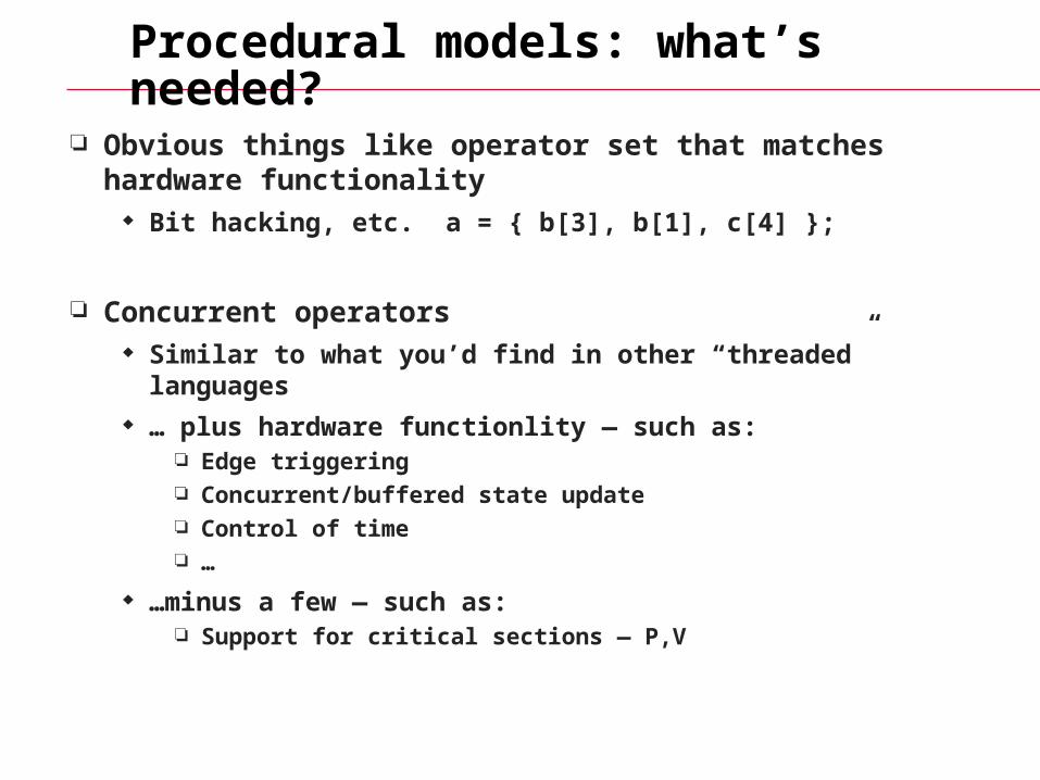
Procedural models: what’s needed?
Obvious things like operator set that matches hardware functionality
Bit hacking, etc. a = { b[3], b[1], c[4] };
Concurrent operators Similar to what you’d find in other “threaded” languages … plus hardware functionlity — such as:
Edge triggering Concurrent/buffered state update Control of time …
…minus a few — such as: Support for critical sections — P,V
Procedural Models
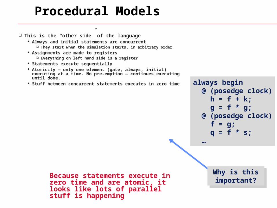
This is the “other side” of the language Always and initial statements are concurrent
They start when the simulation starts, in arbitrary order Assignments are made to registers
Everything on left hand side is a register Statements execute sequentially Atomicity — only one element (gate, always, initial) executing
at a time. No pre-emption — continues executing until done. Stuff between concurrent statements executes in zero time always begin
@ (posedge clock)h = f + k;g = f * g;
@ (posedge clock)f = g;q = f * s;
…
Why is this important?
Why is this important?Because statements execute in zero
time and are atomic, it looks like lots of parallel stuff is happening
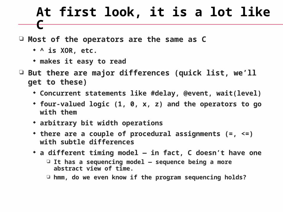
At first look, it is a lot like C
Most of the operators are the same as C ^ is XOR, etc. makes it easy to read
But there are major differences (quick list, we’ll get to these) Concurrent statements like #delay, @event, wait(level) four-valued logic (1, 0, x, z) and the operators to go with them arbitrary bit width operations there are a couple of procedural assignments (=, <=) with subtle
differences a different timing model — in fact, C doesn’t have one
It has a sequencing model — sequence being a more abstract view of time.
hmm, do we even know if the program sequencing holds?
Review from before
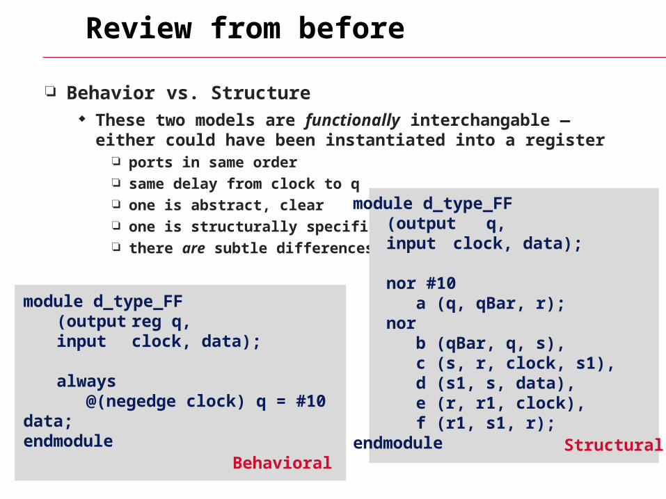
Behavior vs. Structure These two models are functionally interchangable — either could
have been instantiated into a register ports in same order same delay from clock to q one is abstract, clear one is structurally specific there are subtle differences
module d_type_FF (output reg q,
input clock, data);
always @(negedge clock) q = #10 data;endmodule
Behavioral
module d_type_FF (output q,
input clock, data);
nor #10a (q, qBar, r);
norb (qBar, q, s),c (s, r, clock, s1),d (s1, s, data),e (r, r1, clock),f (r1, s1, r);
endmodule Structural
Procedural Timing Model
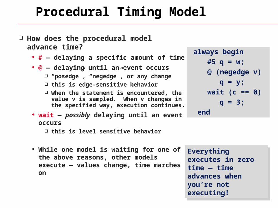
How does the procedural model advance time?
# — delaying a specific amount of time @ — delaying until an event occurs
“posedge”, “negedge”, or any change this is edge-sensitive behavior When the statement is encountered, the
value v is sampled. When v changes in the specified way, execution continues.
wait — possibly delaying until an event occurs
this is level sensitive behavior
While one model is waiting for one of the above reasons, other models execute — values change, time marches on
always begin
#5 q = w;
@ (negedge v)
q = y;
wait (c == 0)
q = 3;
end
Everything executes in zero time — time advances when you’re not executing!
Everything executes in zero time — time advances when you’re not executing!
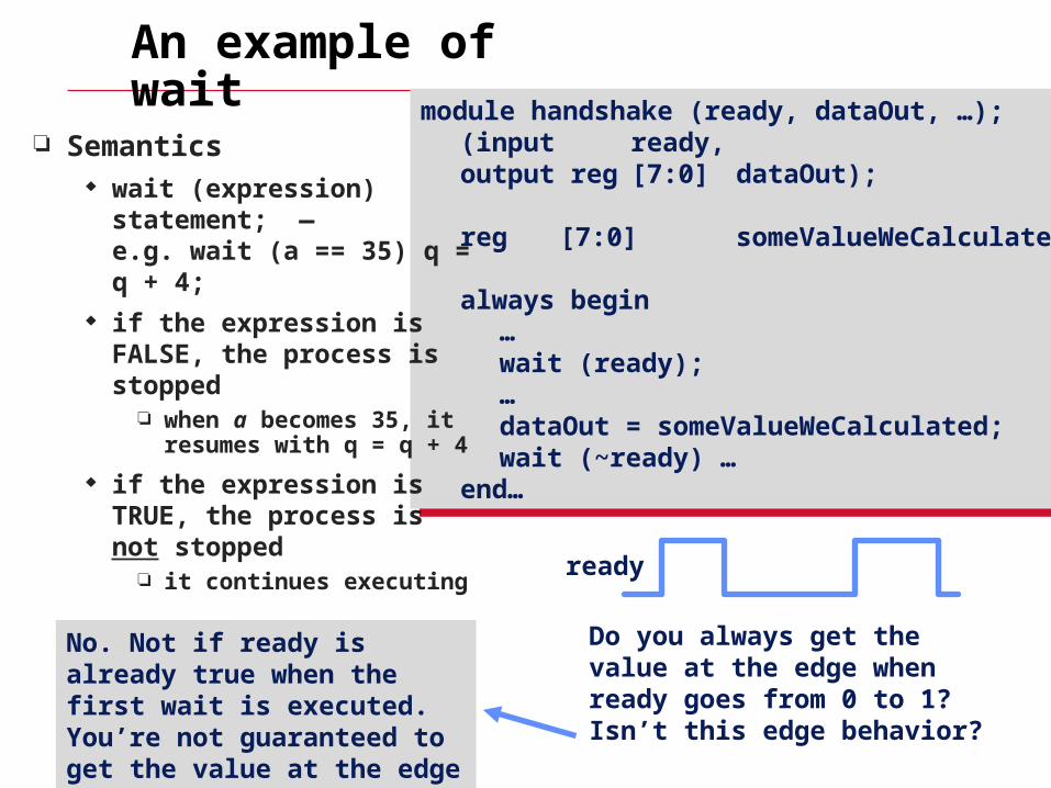
module handshake (ready, dataOut, …);(input ready,output reg [7:0] dataOut);
reg [7:0] someValueWeCalculated;
always begin…wait (ready);…dataOut = someValueWeCalculated;wait (~ready) …
end…
module handshake (ready, dataOut, …);(input ready,output reg [7:0] dataOut);
reg [7:0] someValueWeCalculated;
always begin…wait (ready);…dataOut = someValueWeCalculated;wait (~ready) …
end…
ready
Do you always get the value at the edge when ready goes from 0 to 1? Isn’t this edge behavior?
An example of wait
Semantics wait (expression) statement;
— e.g. wait (a == 35) q = q + 4;
if the expression is FALSE, the process is stopped
when a becomes 35, it resumes with q = q + 4
if the expression is TRUE, the process is not stopped
it continues executing
No. Not if ready is already true when the first wait is executed. You’re not guaranteed to get the value at the edge
Wait vs. While
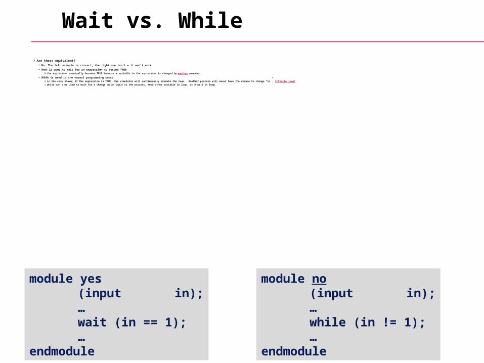
Are these equivalent? No: The left example is correct, the right one isn’t — it won’t work Wait is used to wait for an expression to become TRUE
the expression eventually becomes TRUE because a variable in the expression is changed by another process
While is used in the normal programming sense in the case shown, if the expression is TRUE, the simulator will continuously execute the loop. Another process will never have the chance to change “in”. Infinite loop! while can’t be used to wait for a change on an input to the process. Need other variable in loop, or # or @ in loop.
module yes(input in);…
wait (in == 1); …endmodule
module no(input in);…
while (in != 1); …endmodule
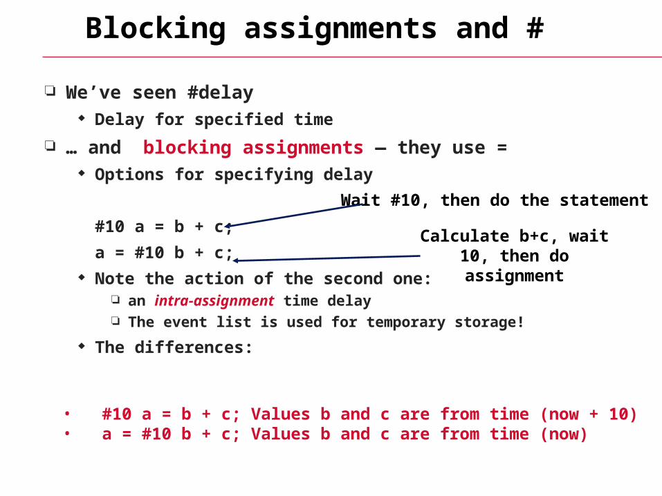
Blocking assignments and #
We’ve seen #delay Delay for specified time
… and blocking assignments — they use = Options for specifying delay
#10 a = b + c;
a = #10 b + c; Note the action of the second one:
an intra-assignment time delay The event list is used for temporary storage!
The differences:
• #10 a = b + c; Values b and c are from time (now + 10)• a = #10 b + c; Values b and c are from time (now)
Wait #10, then do the statement
Calculate b+c, wait 10, then do assignment
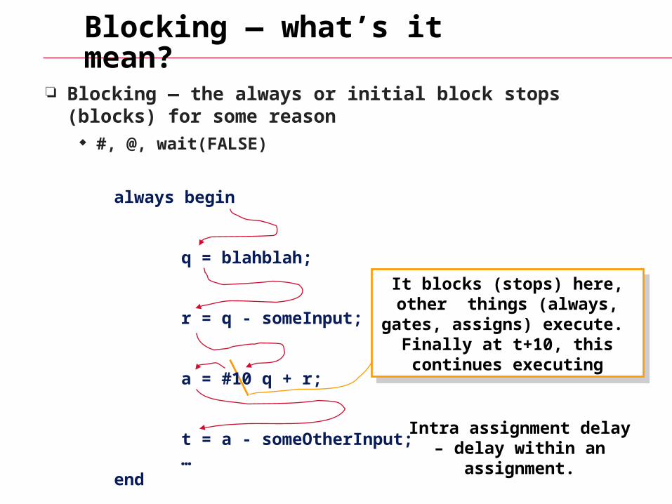
Blocking — what’s it mean?
Blocking — the always or initial block stops (blocks) for some reason
#, @, wait(FALSE)
always begin
q = blahblah;
r = q - someInput;
a = #10 q + r;
t = a - someOtherInput;…
end
It blocks (stops) here, other things (always, gates, assigns)
execute. Finally at t+10, this continues executing
It blocks (stops) here, other things (always, gates, assigns)
execute. Finally at t+10, this continues executing
Intra assignment delay – delay within an assignment.
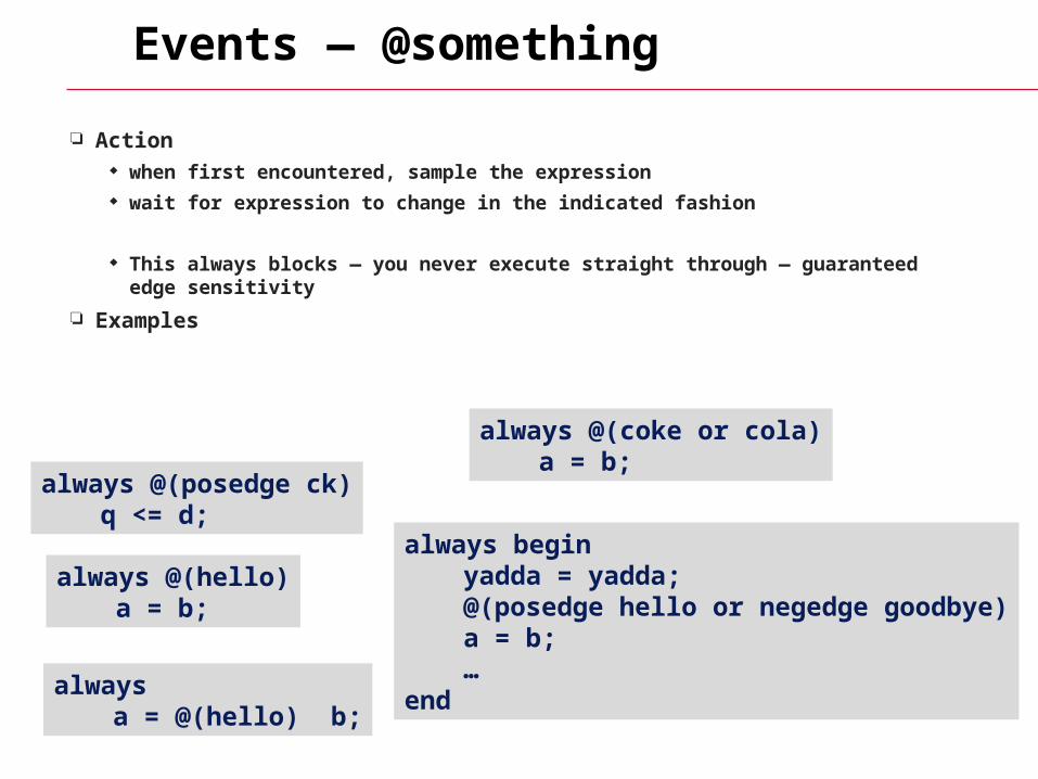
Events — @something
Action when first encountered, sample the expression wait for expression to change in the indicated fashion
This always blocks — you never execute straight through — guaranteed edge sensitivity
Examples
always @(posedge ck)q <= d;
always @(hello)a = b;
always @(coke or cola)a = b;
always beginyadda = yadda;@(posedge hello or negedge goodbye)a = b;…
endalways
a = @(hello) b;
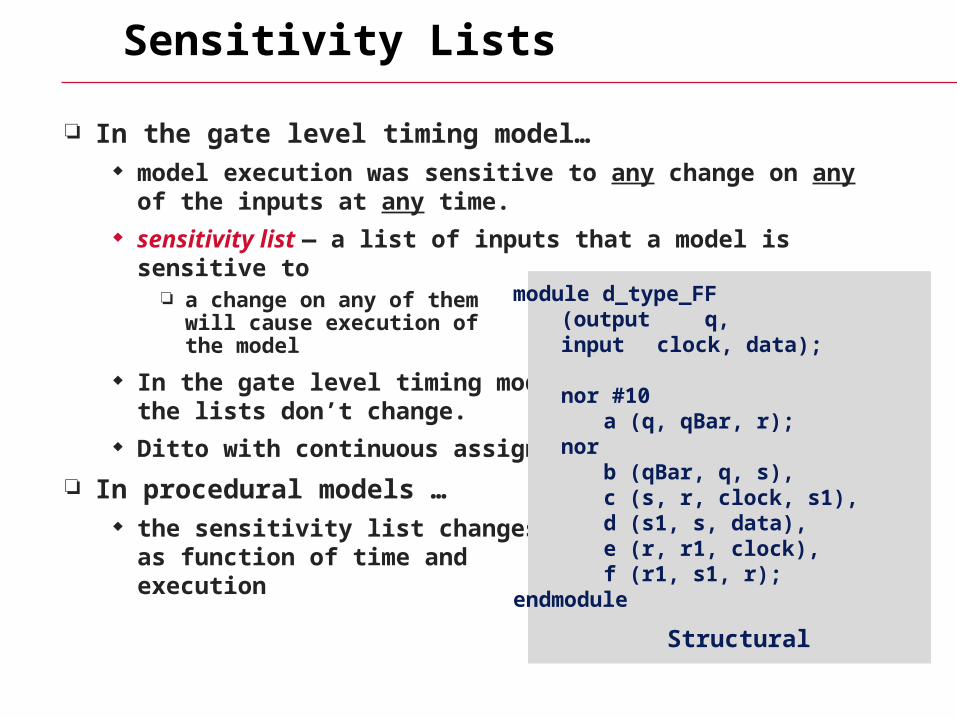
Sensitivity Lists
In the gate level timing model… model execution was sensitive to any change on any of the inputs
at any time. sensitivity list — a list of inputs that a model is sensitive to
a change on any of themwill cause execution ofthe model
In the gate level timing model,the lists don’t change.
Ditto with continuous assign
In procedural models … the sensitivity list changes as
as function of time and execution
module d_type_FF(output q,input clock, data);
nor #10a (q, qBar, r);
norb (qBar, q, s),c (s, r, clock, s1),d (s1, s, data),e (r, r1, clock),f (r1, s1, r);
endmodule
Structural
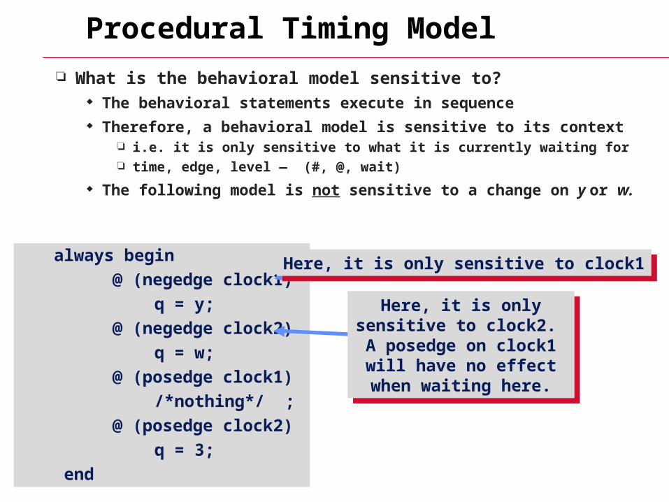
Procedural Timing Model
What is the behavioral model sensitive to? The behavioral statements execute in sequence Therefore, a behavioral model is sensitive to its context
i.e. it is only sensitive to what it is currently waiting for time, edge, level — (#, @, wait)
The following model is not sensitive to a change on y or w.
always begin
@ (negedge clock1)
q = y;
@ (negedge clock2)
q = w;
@ (posedge clock1)
/*nothing*/ ;
@ (posedge clock2)
q = 3;
end
Here, it is only sensitive to clock1Here, it is only sensitive to clock1
Here, it is only sensitive to clock2. A posedge on
clock1 will have no effect when waiting here.
Here, it is only sensitive to clock2. A posedge on
clock1 will have no effect when waiting here.
Fanout Lists
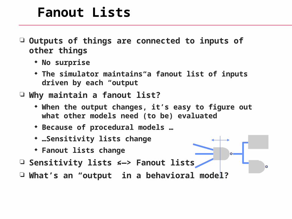
Outputs of things are connected to inputs of other things No surprise The simulator maintains a fanout list of inputs driven by each
“output”
Why maintain a fanout list? When the output changes, it’s easy to figure out what other
models need (to be) evaluated Because of procedural models … …Sensitivity lists change Fanout lists change
Sensitivity lists <—> Fanout lists
What’s an “output” in a behavioral model?
List Changes
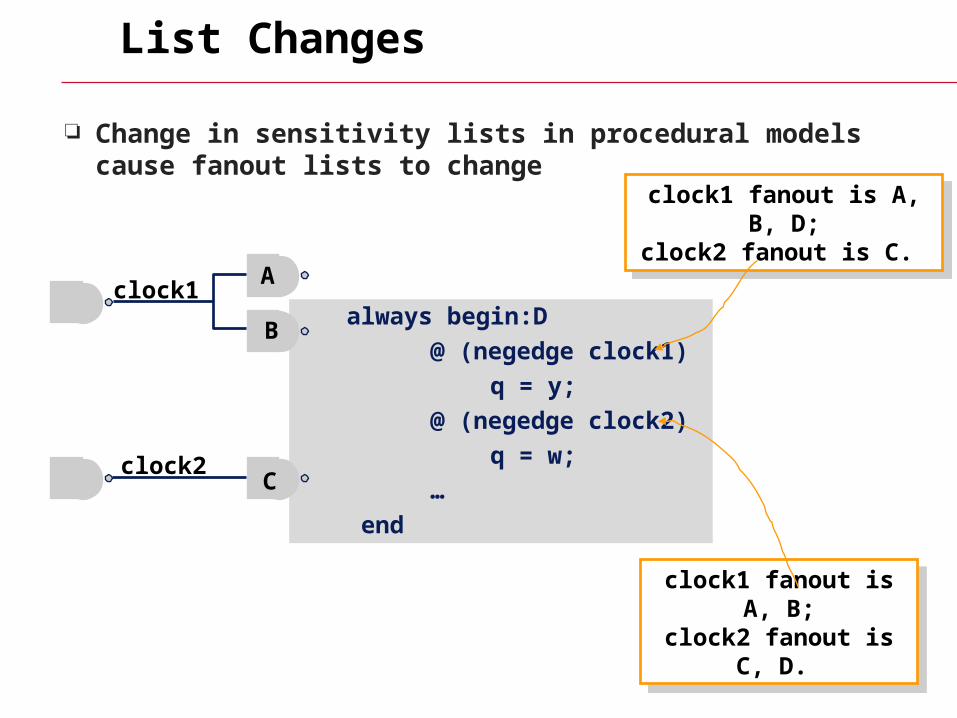
Change in sensitivity lists in procedural models cause fanout lists to change
always begin:D
@ (negedge clock1)
q = y;
@ (negedge clock2)
q = w;
…
end
clock1A
B
clock2C
clock1 fanout is A, B, D;clock2 fanout is C.
clock1 fanout is A, B, D;clock2 fanout is C.
clock1 fanout is A, B;clock2 fanout is C, D.
clock1 fanout is A, B;clock2 fanout is C, D.
Scheduling #, @, and Wait
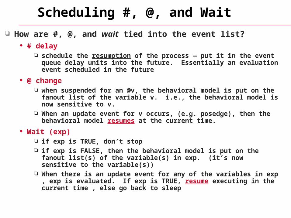
How are #, @, and wait tied into the event list? # delay
schedule the resumption of the process — put it in the event queue delay units into the future. Essentially an evaluation event scheduled in the future
@ change when suspended for an @v, the behavioral model is put on the fanout list of
the variable v. i.e., the behavioral model is now sensitive to v. When an update event for v occurs, (e.g. posedge), then the behavioral model
resumes at the current time.
Wait (exp) if exp is TRUE, don’t stop if exp is FALSE, then the behavioral model is put on the fanout list(s) of the
variable(s) in exp. (it’s now sensitive to the variable(s)) When there is an update event for any of the variables in exp , exp is
evaluated. If exp is TRUE, resume executing in the current time , else go back to sleep
Procedural Model Sensitivity?
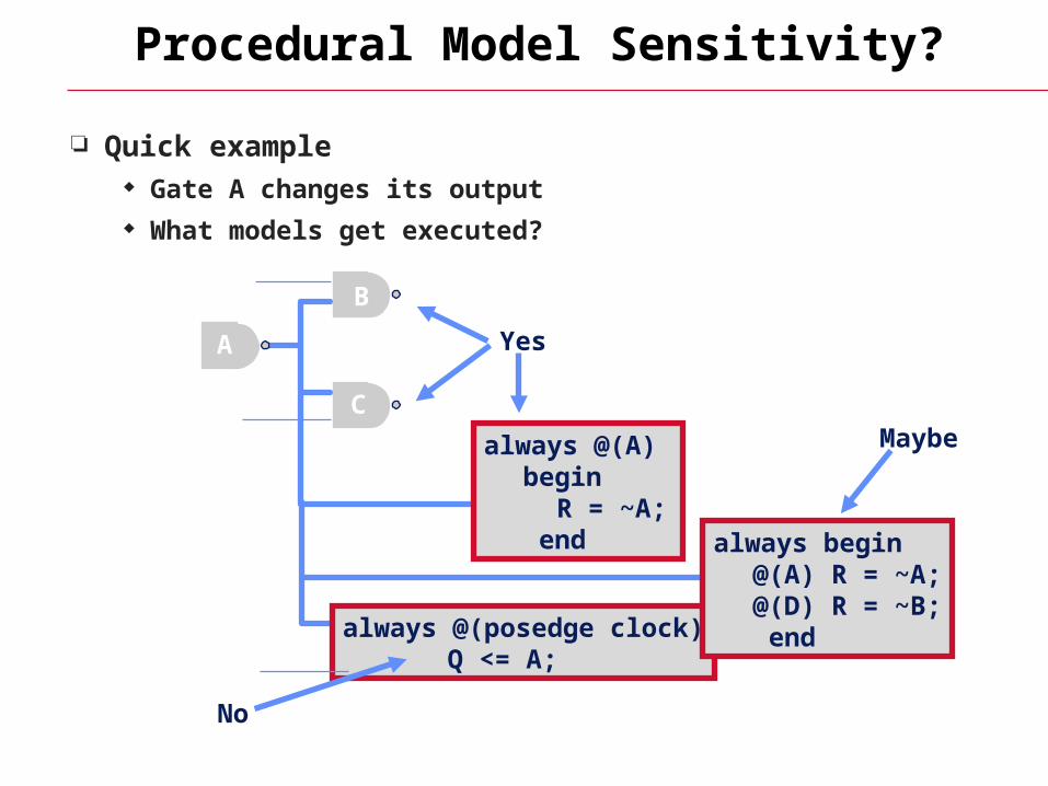
Quick example Gate A changes its output What models get executed?
A
B
C
always @(A) begin
R = ~A; end
always @(posedge clock)Q <= A;
always begin@(A) R = ~A;@(D) R = ~B; end
No
Yes
Maybe
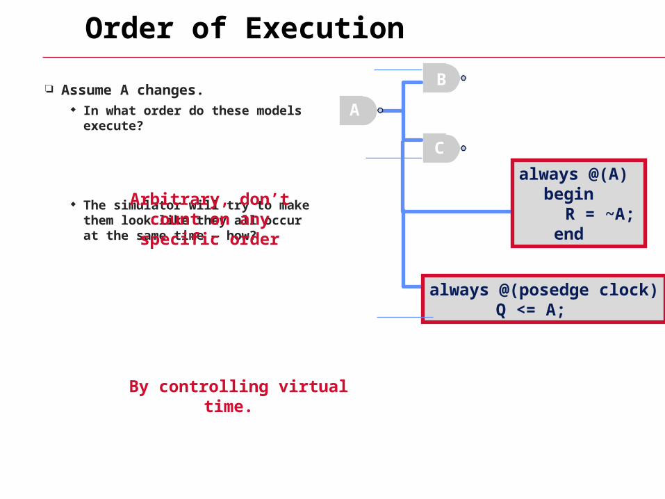
Order of Execution
Assume A changes. In what order do these models
execute?
The simulator will try to make them look like they all occur at the same time — how?
A
B
C
always @(A) begin
R = ~A; end
always @(posedge clock)Q <= A;
Arbitrary, don’t count on any specific order
By controlling virtual time.
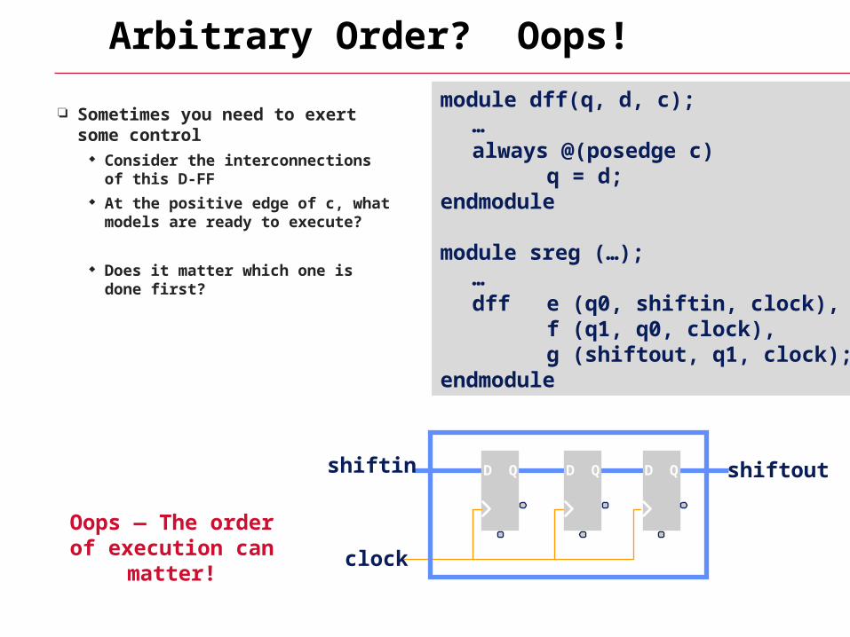
Arbitrary Order? Oops!
Sometimes you need to exert some control
Consider the interconnections of this D-FF
At the positive edge of c, what models are ready to execute?
Does it matter which one is done first?
module dff(q, d, c);…always @(posedge c)
q = d;endmodule
module sreg (…);…dff e (q0, shiftin, clock),
f (q1, q0, clock),g (shiftout, q1, clock);
endmodule
QDQD QD
clock
shiftin shiftout
Oops — The order of execution can matter!
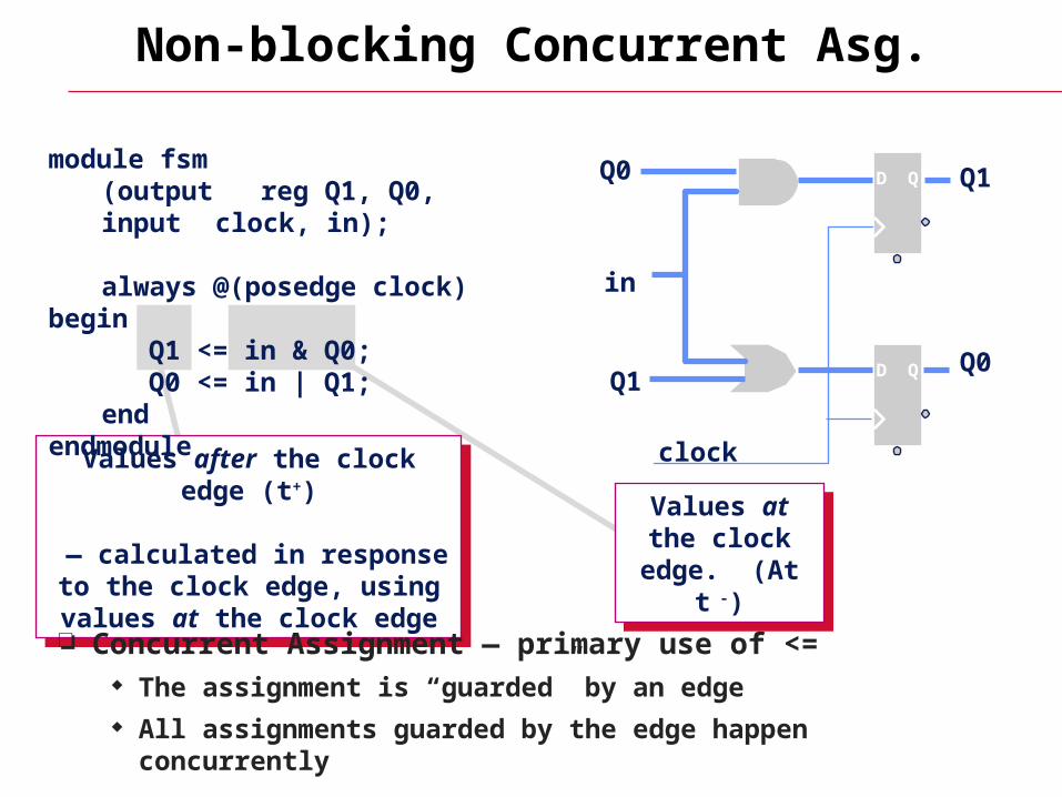
Non-blocking Concurrent Asg.
QD
QD
in
Q1
Q0Q1
Q0
clock
Values at the clock edge.
(At t -)
Values at the clock edge.
(At t -)
Values after the clock edge (t+)
— calculated in response to the clock edge, using values at
the clock edge
Values after the clock edge (t+)
— calculated in response to the clock edge, using values at
the clock edge
module fsm(output reg Q1, Q0,input clock, in);
always @(posedge clock) beginQ1 <= in & Q0;Q0 <= in | Q1;
endendmodule
Concurrent Assignment — primary use of <= The assignment is “guarded” by an edge All assignments guarded by the edge happen concurrently


![Verilog HDL - actel.kractel.kr/_hdl/4/_course/iax8165/~lrv/verilog.pdf · Ken Coffman, “Real world FPGA design with Verilog.” Prentice Hall [2000] Donald E. Thomas, Philip R](https://img.pdfslide.net/doc/110x75/5edad56609ac2c67fa68615f/verilog-hdl-actel-lrvverilogpdf-ken-coffman-aoereal-world-fpga-design-with.jpg)