Embed Size (px)
Citation preview
The Virtual LANTechnology Report
The Virtual LANTechnology Report
decisys
1
The Virtual LAN Technology Report
ContentsIntroduction 2
Defining VLANs 3
Membership by Port Group 3
Membership by MAC Address 3
Layer 3–Based VLANs 4
IP Multicast Groups as VLANs 5
Combination VLAN Definitions 5
Automation of VLAN Configuration 5
Communicating VLAN Membership Information 6
Standards and the Proprietary Nature of VLANs 6
VLAN Implementation Benefits 7
Reducing the Cost of Moves and Changes 7
Virtual Workgroups 8
Reduction of Routing for Broadcast Containment 9
Routing Between VLANs 10
VLANs Over the WAN 11
Security 11
VLANs and ATM 11
VLANs Transparent to ATM 11
Complexity Arising with ATM-Attached Devices 11
LAN Emulation 11
Routing Between Emulated LANs and/or VLANs 13
Edge Routing 14
The One-Armed Router 14
The Route Server 14
MPOA 15
VLANs and DHCP: Overlapping Solutions 15
DHCP Functionality 16
Best Use for Each 16
Overlap Between DHCP and VLANs 16
VLAN Architectures Going Forward 17
Infrastructural VLANs 17
Service-Based VLANs 18
VLAN Migration Strategies 19
Conclusion 20
Copyright©1996.
The Virtual LAN Technology Report
by David Passmore and John Freeman
IntroductionVirtual LANs (VLANs) have recentlydeveloped into an integral feature of switchedLAN solutions from every major LANequipment vendor. Although end-userenthusiasm for VLAN implementation has yetto take off, most organizations have begun tolook for vendors that have a well-articulatedVLAN strategy, as well as VLAN func-tionality built into products today. One of thereasons for the attention placed on VLANfunctionality now is the rapid deployment ofLAN switching that began in 1994/1995.
The shift toward LAN switching as areplacement for local/departmental routers—and now even shared media devices (hubs)—will only accelerate in the future. With therapid decrease in Ethernet and Token Ringswitch prices on a per-port basis, many moreambitious organizations are moving quicklytoward networks featuring private port (singleuser/port) LAN switching architectures. Such adesktop switching architecture is ideally suitedto VLAN implementation. To understand whyprivate port LAN switching is so well suited toVLAN implementation, it is useful to reviewthe evolution of segmentation and broadcastcontainment in the network over the pastseveral years.
In the early 1990s, organizations began toreplace two-port bridges with multiport, col-lapsed backbone routers in order to segmenttheir networks at layer 3 and thus also containbroadcast traffic. In a network using onlyrouters for segmentation, segments andbroadcast domains correspond on a one-to-onebasis. Each segment typically containedbetween 30 and 100 users.
With the introduction of switching, orga-nizations were able to divide the network intosmaller, layer 2–defined segments, enablingincreased bandwidth per segment. Routerscould now focus on providing broadcast con-tainment, and broadcast domains could nowspan multiple switched segments, easily sup-porting 500 or more users per broadcastdomain. However, the continued deployment
of switches, dividing the network into moreand more segments (with fewer and fewerusers per segment) does not reduce the needfor broadcast containment. Using routers,broadcast domains typically remain in the 100to 500 user range.
VLANs represent an alternative solutionto routers for broadcast containment, sinceVLANs allow switches to also containbroadcast traffic. With the implementation ofswitches in conjunction with VLANs, eachnetwork segment can contain as few as oneuser (approaching private port LAN switch-ing), while broadcast domains can be as largeas 1,000 users or perhaps even more. Inaddition, if implemented properly, VLANs cantrack workstation movements to new locationswithout requiring manual reconfiguration of IPaddresses.
Why haven’t more organizations deployedVLANs? For the vast majority of end-userorganizations, switches have yet to be imple-mented on a large enough scale to necessitateVLANs. That situation will soon change.There are, however, other reasons for thelukewarm reception that VLANs have receivedfrom network users up to now:• VLANs have been, and are still, proprietary,
single-vendor solutions. As the networkingindustry has shown, proprietary solutions areanathema to the multivendor/open systemspolicies that have developed in the migrationto local area networks and the client servermodel.
• Despite the frequently quoted numbers illu-minating the hidden costs of networking,such as administration and moves/adds/changes, customers realize that VLANs havetheir own administrative costs, both straight-forward and hidden.
• Although many analysts have suggested thatVLANs enhance the ability to deploy cen-tralized servers, customers may look atenterprise-wide VLAN implementation andsee difficulties in enabling full, high-per-formance access to centralized servers.
This paper discusses these and otherissues in greater detail, and attempts todetermine the strategic implications thatVLANs, present and future, pose for enterprisenetworks.
2
David Passmore is presidentand co-founder of Decisys, Inc.,a Sterling, Virginia–based con-sulting firm specializing innetwork design, architecture,and management for end-userorganizations, and networkproduct marketing and strategicplanning for vendors. Beforefounding Decisys, David wasvice president of the GartnerGroup and a partner in Ernst &Young’s Center for InformationTechnology and Strategy inBoston, Massachusetts.
David received a B.S. incomputer science and engi-neering and an M.S. in elec-trical engineering andcomputer science, both fromthe Massachusetts Institute ofTechnology.
Defining VLANsWhat is a VLAN? With the multitude ofvendor-specific VLAN solutions and imple-mentation strategies, defining precisely whatVLANs are has become a contentious issue.Nevertheless, most people would agree that aVLAN can be roughly equated to a broadcastdomain. More specifically, VLANs can beseen as analogous to a group of end-stations,perhaps on multiple physical LAN segments,that are not constrained by their physicallocation and can communicate as if they wereon a common LAN.
However, at this point, issues such as theextent to which end-stations are not con-strained by physical location, the way VLANmembership is defined, the relationshipbetween VLANs and routing, and the rela-tionship between VLANs and ATM have beenleft up to each vendor. To a certain extent theseare tactical issues, but how they are resolvedhas important strategic implications.
Because there are several ways in whichVLAN membership can be defined, this paperdivides VLAN solutions into four generaltypes: port grouping, MAC-layer grouping,network-layer grouping, and IP multicastgrouping. We will discuss the issue of manualvs. automatic VLAN configuration, anddescribe techniques by which VLANs may beextended across multiple switches in thenetwork. Finally, the paper takes a look at thepresent state of VLAN standards.
Membership by Port GroupMany initial VLAN implementations definedVLAN membership by groups of switch
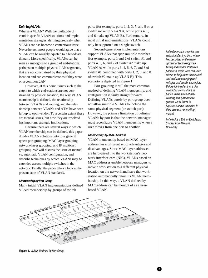
ports (for example, ports 1, 2, 3, 7, and 8 on aswitch make up VLAN A, while ports 4, 5,and 6 make up VLAN B). Furthermore, inmost initial implementations, VLANs couldonly be supported on a single switch.
Second-generation implementationssupport VLANs that span multiple switches(for example, ports 1 and 2 of switch #1 andports 4, 5, 6, and 7 of switch #2 make upVLAN A; while ports 3, 4, 5, 6, 7, and 8 ofswitch #1 combined with ports 1, 2, 3, and 8of switch #2 make up VLAN B). Thisscenario is depicted in Figure 1.
Port grouping is still the most commonmethod of defining VLAN membership, andconfiguration is fairly straightforward.Defining VLANs purely by port group doesnot allow multiple VLANs to include thesame physical segment (or switch port).However, the primary limitation of definingVLANs by port is that the network managermust reconfigure VLAN membership when auser moves from one port to another.
Membership by MAC AddressVLAN membership based on MAC-layeraddress has a different set of advantages anddisadvantages. Since MAC-layer addressesare hard-wired into the workstation’s net-work interface card (NIC), VLANs based onMAC addresses enable network managers tomove a workstation to a different physicallocation on the network and have that work-station automatically retain its VLAN mem-bership. In this way, a VLAN defined byMAC address can be thought of as a user-based VLAN.
3
Switch #1
1 2 3 4 5 6 7 81 2 3 4 5 6 7 8
Hub
Hub
Switch #2
VLAN A
VLAN B
Backbone/backplane connecting multiple switches
Hub
Figure 1. VLANs Defined by Port Group
John Freeman is a senior con-sultant at Decisys, Inc., wherehe specializes in the devel-opment of technology mar-keting and vendor strategies.John also works with end-userclients to help them understandand evaluate emerging tech-nologies and vendor strategies.Before joining Decisys, Johnworked as a consultant inJapan in the areas of net-working and systems inte-gration. He is fluent inJapanese and is an expert inthe Japanese networkingmarket.
John holds a B.A. in East AsianStudies from HarvardUniversity.
One of the drawbacks of MACaddress–based VLAN solutions is the require-ment that all users must initially be configuredto be in at least one VLAN. After that initialmanual configuration, automatic tracking ofusers is possible, depending on the specificvendor solution. However, the disadvantage ofhaving to initially configure VLANs becomesclear in very large networks where thousands ofusers must each be explicitly assigned to a par-ticular VLAN. Some vendors have mitigatedthe onerous task of initially configuring MAC-based VLANs by using tools that createVLANs based on the current state of thenetwork—that is, a MAC address–basedVLAN is created for each subnet.
MAC address–based VLANs that areimplemented in shared media environmentswill run into serious performance degradationas members of different VLANs coexist on asingle switch port. In addition, the primarymethod of communicating VLAN membershipinformation between switches in a MACaddress–defined VLAN also runs into per-formance degradation with larger-scale imple-mentations. This is explained in “Communi-cating VLAN Membership Information,” laterin this paper.
Another, but minor, drawback to VLANsbased only on MAC-layer addresses emergesin environments that use significant numbersof notebook PCs with some docking stations.The problem is that the docking station andintegrated network adapter (with its hard-wiredMAC-layer address) usually remain on thedesktop, while the notebook travels with theuser. When the user moves to a new desk anddocking station, the MAC-layer addresschanges, making VLAN membershipimpossible to track. In such an environment,VLAN membership must be updated con-stantly as users move around and use differentdocking stations. While this problem may notbe particularly common, it does illustrate someof the limitations of MAC address–basedVLANs.
Layer 3–Based VLANsVLANs based on layer 3 information take intoaccount protocol type (if multiple protocols
are supported) or network-layer address (forexample, subnet address for TCP/IP networks)in determining VLAN membership. Althoughthese VLANs are based on layer 3 infor-mation, this does not constitute a “routing”function and should not be confused withnetwork-layer routing.
Even though a switch inspects a packet’sIP address to determine VLAN membership,no route calculation is undertaken, RIP orOSPF protocols are not employed, and framestraversing the switch are usually bridgedaccording to implementation of the SpanningTree Algorithm. Therefore, from the point ofview of a switch employing layer 3–basedVLANs, connectivity within any given VLANis still seen as a flat, bridged topology.
Having made the distinction betweenVLANs based on layer 3 information androuting, it should be noted that some vendorsare incorporating varying amounts of layer 3intelligence into their switches, enablingfunctions normally associated with routing.Furthermore, “layer 3 aware” or “multi-layer”switches often have the packet-forwardingfunction of routing built into ASIC chip sets,greatly improving performance over CPU-based routers. Nevertheless, a key pointremains: no matter where it is located in aVLAN solution, routing is necessary toprovide connectivity between distinct VLANs.
There are several advantages to definingVLANs at layer 3. First, it enables partitioningby protocol type. This may be an attractiveoption for network managers who are ded-icated to a service- or application-based VLANstrategy. Second, users can physically movetheir workstations without having to recon-figure each workstation’s network address—abenefit primarily for TCP/IP users. Third,defining VLANs at layer 3 can eliminate theneed for frame tagging in order to commu-nicate VLAN membership between switches,reducing transport overhead.
One of the disadvantages of definingVLANs at layer 3 (vs. MAC- or port-basedVLANs) can be performance. Inspectinglayer 3 addresses in packets is more time con-suming than looking at MAC addresses inframes. For this reason, switches that use
4
Acronyms andAbbreviations
AAL5ATM Adaptation Layer Type 5
ASICApplication-specific integratedcircuit
ATMAsynchronous Transfer Mode
DHCPDynamic Host ConfigurationProtocol
ELANEmulated LAN
FDDIFiber Distributed Data Interface
IPXInternet Packet Exchange
LANELAN Emulation
LECLAN Emulation client
LESLAN Emulation server
layer 3 information for VLAN definition aregenerally slower than those that use layer 2information. It should be noted that this per-formance difference is true for most, but notall, vendor implementations.
VLANs defined at layer 3 are particularlyeffective in dealing with TCP/IP, but lesseffective with protocols such as IPX™,DECnet®, or AppleTalk®, which do notinvolve manual configuration at the desktop.Furthermore, layer 3–defined VLANs haveparticular difficulty in dealing with “unrout-able” protocols such as NetBIOS. End-stations running unroutable protocols cannotbe differentiated and thus cannot be definedas part of a network-layer VLAN.
IP Multicast Groups as VLANsIP multicast groups represent a somewhat dif-ferent approach to VLAN definition, althoughthe fundamental concept of VLANs asbroadcast domains still applies. When an IPpacket is sent via multicast, it is sent to anaddress that is a proxy for an explicitly definedgroup of IP addresses that isestablished dynamically.Each workstation is giventhe opportunity to join aparticular IP multicast groupby responding affirmativelyto a broadcast notification,which signals that group’sexistence. All workstationsthat join an IP multicastgroup can be seen asmembers of the same virtualLAN. However, they areonly members of a particular multicast groupfor a certain period of time. Therefore, thedynamic nature of VLANs defined by IP mul-ticast groups enables a very high degree offlexibility and application sensitivity. Inaddition, VLANs defined by IP multicastgroups would inherently be able to spanrouters and thus WAN connections.
Combination VLAN DefinitionsDue to the trade-offs between various types ofVLANs, many vendors are planning to includemultiple methods of VLAN definition. Such a
flexible definition of VLAN membershipenables network managers to configure theirVLANs to best suit their particular networkenvironment. For example, by using a combi-nation of methods, an organization that utilizesboth IP and NetBIOS protocols could define IPVLANs corresponding to preexisting IPsubnets (convenient for smooth migration),and then define VLANs for NetBIOS end-stations by dividing them by groups of MAC-layer addresses.
Automation of VLAN ConfigurationAnother issue central to VLAN deployment isthe degree to which VLAN configuration isautomated. To a certain extent, this degree ofautomation is correlated to how VLANs aredefined; but in the end, the specific vendorsolution will determine this level of auto-mation. There are three primary levels ofautomation in VLAN configuration:• Manual. With purely manual VLAN config-
uration, both the initial setup and all sub-sequent moves and changes are controlled
by the network adminis-trator. Of course, purelymanual configurationenables a high degree ofcontrol. However, inlarger enterprisenetworks, manual config-uration is often notpractical. Furthermore, itdefeats one of theprimary benefits ofVLANs: elimination ofthe time it takes to
administer moves and changes—althoughmoving users manually with VLANs mayactually be easier than moving users acrossrouter subnets, depending on the specificvendor’s VLAN management interface.
• Semiautomated. Semiautomated configu-ration refers to the option to automate eitherinitial configuration, subsequent reconfigu-rations (moves/changes), or both. Initial con-figuration automation is normally accomp-lished with a set of tools that map VLANs toexisting subnets or other criteria. Semi-automated configuration could also refer to
5
Acronyms andAbbreviations (Cont.)
MACMedia access control
MPOAMultiprotocol over ATM
NICNetwork interface card
OSPFOpen Shortest Path First
PVCPermanent virtual circuit
RIPRouting Information Protocol
SVCSwitched virtual circuit
TCP/IPTransmission ControlProtocol/Internet Protocol
TDMTime-division multiplexing
The dynamicnature of VLANsdefined by IPmulticast groupsenables a veryhigh degree offlexibility andapplication sensitivity.
situations where VLANs are initially con-figured manually, with all subsequentmoves being tracked automatically. Com-bining both initial and subsequent configu-ration automation would still imply semi-automated configuration, because thenetwork administrator always has the optionof manual configuration.
• Fully Automatic. A system that fullyautomates VLAN configuration implies thatworkstations automatically and dynamicallyjoin VLANs depending on application, userID, or other criteria or policies that are presetby the administrator. This type of VLANconfiguration is discussed in greater detailtoward the end of this paper.
Communicating VLAN Membership InformationSwitches must have a way of understandingVLAN membership (that is, which stationsbelong to which VLAN) when network trafficarrives from other switches; otherwise,VLANs would be limited to a single switch. Ingeneral, layer 2–based VLANs (defined byport or MAC address) must communicateVLAN membership explicitly, while VLANmembership in IP-based VLANs is implicitlycommunicated by the IP address. Dependingon the particular vendor’s solution, communi-cation of VLAN membership may also beimplicit in the case of layer 3–based VLANs ina multiprotocol environment.
To date, outside of implementing an ATMbackbone, three methods have been imple-mented for interswitch communication ofVLAN information across a backbone: tablemaintenance via signaling, frame tagging, andtime-division multiplexing (TDM).• Table Maintenance via Signaling. This
method operates as follows: When an end-station broadcasts its first frame, the switchresolves the end-station’s MAC address orattached port with its VLAN membership incached address tables. This information isthen broadcast continuously to all otherswitches. As VLAN membership changes,these address tables are manually updated bya system administrator at a managementconsole. As the network expands andswitches are added, the constant signaling
necessary to update the cached addresstables of each switch can cause substantialcongestion of the backbone. For this reason,this method does not scale particularly well.
• Frame Tagging. In the frame-taggingapproach, a header is typically inserted intoeach frame on interswitch trunks touniquely identify which VLAN a particularMAC-layer frame belongs to. Vendorsdiffer in the way they solve the problem ofoccasionally exceeding the maximumlength of MAC-layer frames as theseheaders are inserted. These headers also addoverhead to network traffic.
• TDM. The third, and least utilized method, istime-division multiplexing. TDM works thesame way on the interswitch backbone tosupport VLANs as it does in the WAN envi-ronment to support multiple traffic types—here, channels are reserved for each VLAN.This approach cuts out some of the overheadproblems inherent in signaling and frametagging, but it also wastes bandwidth,because a time slot dedicated to one VLANcannot be used by another VLAN, even ifthat channel is not carrying traffic.
Deploying an ATM backbone also enablesthe communication of VLAN informationbetween switches, but it introduces a new setof issues with regard to LAN Emulation(LANE). ATM is discussed in detail in aseparate section of this paper. However, for thetime being, it should be remembered that withport group–defined VLANs, the LANEstandard provides for a nonproprietary methodof communicating VLAN membership acrossa backbone.
Standards and the Proprietary Nature of VLANsGiven the variety of types of VLAN defin-itions and the variety of ways that switches cancommunicate VLAN information, it should notbe surprising that each vendor has developedits own unique and proprietary VLANsolutions and products. The fact that switchesfrom one vendor will not interoperate entirelywith VLANs from other vendors may forcecustomers to buy from a single vendor forVLAN deployment across the enterprise. Anexception to this rule arises when VLANs are
6
implemented in conjunction with an ATMbackbone and LANE. This is discussed furtherin “VLANs and ATM,” later in this paper.
The fact that single-vendor VLANsolutions in the LAN backbone will be the rulefor the foreseeable future contributes to therecommendation that VLANs should not bedeployed indiscriminately throughout theenterprise. It also implies that purchasedecisions should be more highly centralized orcoordinated than they may traditionally havebeen. Thus, from both a procurement and atechnological perspective, VLANs should beconsidered as elements of a strategic approach.
The following twoVLAN standards have beenproposed:• 802.10 “VLAN
Standard.” In 1995,Cisco Systems proposedthe use of IEEE 802.10,which was originallyestablished to addressLAN security forVLANs. Cisco attemptedto take the optional802.10 frame headerformat and “reuse” it toconvey VLAN frametagging instead ofsecurity information. Although this can bemade to work technically, most members ofthe 802 committee have been stronglyopposed to using one standard for twodiscrete purposes. In addition, this solutionwould be based on variable-length fields,which make implementation of ASIC-basedframe processing more difficult and thusslower and/or more expensive.
• 802.1 Internetworking Subcommittee. InMarch, 1996, the IEEE 802.1 Internet-working Subcommittee completed the initialphase of investigation for developing aVLAN standard, and passed resolutions con-cerning three issues: the architecturalapproach to VLANs; a standardized formatfor frame tagging to communicate VLANmembership information across multiple,multivendor devices; and the future directionof VLAN standardization. The standardized
format for frame tagging, in particular,known as 802.1Q, represents a majormilestone in enabling VLANs to be imple-mented using equipment from severalvendors, and will be key in encouragingmore rapid deployment of VLANs.Furthermore, establishment of a frameformat specification will allow vendors toimmediately begin incorporating thisstandard into their switches. All majorswitch vendors, including 3Com, Alantec/FORE, Bay Networks, Cisco, and IBMvoted in favor of this proposal.
However, due to the lag time necessary forsome vendors to incorporatethe frame format specifi-cation and the desire on thepart of most organizations tohave a unified VLAN man-agement platform, VLANswill, in practice, continue toretain characteristics of asingle-vendor solution forsome time. This has sig-nificant ramifications fordeployment and pro-curement of VLANs.Department-level pro-curement for LANequipment, particularly in
the backbone, is not practical for organizationsdeploying VLANs. Purchasing decisions andstandardization on a particular vendor’ssolution throughout the enterprise will becomethe norm, and price-based product competitionwill decrease. The structure of the industryitself may also shift in favor of the larger net-working vendors that can furnish a completesolution across a wide range of components.
VLAN Implementation BenefitsWhy are vendors paying so much attention toVLAN implementation? Will VLANs solveall of the network manager’s problems withrespect to moves, changes, broadcasts, andperformance?
Reducing the Cost of Moves and ChangesThe reason most often given for VLAN imple-mentation is a reduction in the cost of handling
7
The standard-ized format forframe tagging,known as802.1Q, rep-resents a majormilestone inenabling VLANsto be imple-mented usingequipmentfrom severalvendors.
user moves and changes. Since these costs arequite substantial, this argument for VLANimplementation can be compelling.
Many venders are promising that VLANimplementation will result in a vastly increasedability to manage dynamic networks andrealize substantial cost savings. This valueproposition is most valid for IP networks.Normally, when a user moves to a differentsubnet, IP addresses must be manually updatedin the workstation. This updating process canconsume a substantial amount of time thatcould be used for more productive endeavorssuch as developing new network services.VLANs eliminate that hassle, because VLANmembership is not tied to a workstation’slocation in the network, allowing moved work-stations to retain their original IP addresses andsubnet membership.
It is certainly true that the phenomenon ofincreasingly dynamic networks absorbs a sub-stantial portion of the budgets of most ISdepartments. However, not just any VLANimplementation will reduce these costs.VLANs themselves add another layer ofvirtual connectivity that must be managed inconjunction with physical connectivity. This isnot to say that VLANs cannot reduce the costsof moves, and changes—if properly imple-mented, they will. However, organizationsmust be careful not to simply throw VLANs atthe network, and they must make sure that thesolution does not generate more networkadministration than it saves.
Virtual WorkgroupsOne of the more ambitious VLAN objectivesis the establishment of the virtual workgroupmodel. The concept is that, with full VLANimplementation across the campus networkenvironment, members of the same departmentor section can all appear to share the same“LAN,” with most of the network trafficstaying within the same VLAN broadcastdomain. Someone moving to a new physicallocation but remaining in the same departmentcould move without having workstationsreconfigured. Conversely, a user would nothave to change his or her physical locationwhen changing departments—the network
manager would simply change the user’sVLAN membership.
This functionality promises to enable amore dynamic organizational environment,enhancing the recent trend toward cross-func-tional teams. The logic of the virtual work-group model goes like this: teams formed on atemporary, project basis could be virtually con-nected to the same LAN without requiringpeople to physically move in order to minimizetraffic across a collapsed backbone. Addition-ally, these workgroups would be dynamic:VLANs corresponding to these cross-func-tional project teams could be set up for theduration of the project and torn down when theproject was completed, all the while allowingusers to remain in the same physical locations.
Although this scenario seems attractive,the reality is that VLANs alone cannot pavethe way for full utilization of the virtualworkgroup model. There are several man-agerial and architectural issues that, at thispoint, pose problems for the virtualworkgroup model:• Managing Virtual Workgroups. From a
network management perspective, the tran-sitory nature of these virtual workgroupsmay grow to the point where updatingVLAN membership becomes as onerous asupdating routing tables to keep up with adds,moves, and changes today (although it maysave on the time and effort involved in phys-ically moving the user’s workstation).Moreover, there are still cultural hurdles toovercome in the virtual workgroup model:people usually move to be physically closeto those with whom they work, rather than toreduce traffic across a collapsed backbone.
• Maintaining the 80/20 Rule. Virtual LANsupport for virtual workgroups is often tiedto support of the “80/20 rule,” that is, 80percent of the traffic is “local” to theworkgroup while 20 percent is remote oroutside of the workgroup. In theory, byproperly configuring VLANs to matchworkgroups, only the 20 percent of thetraffic that is nonlocal will need to passthrough a router and out of the workgroup,improving performance for the 80 percent ofthe traffic that is within the workgroup.
8
However, many believe that the applicabilityof the 80/20 rule is waning due to thedeployment of servers and/or network appli-cations such as e-mail and Lotus Notes® thatusers throughout the enterprise access on anequal basis.
• Access to Local Network Resources. Thevirtual workgroup concept may run into thesimple problem that users must sometimes bephysically close to certain resources such asprinters. For example, a user is in theAccounting VLAN, but is physically locatedin an area populated by members of the SalesVLAN. The local network printer is also inthe Sales VLAN. Every time this AccountingVLAN member prints to the local printer, hisprint file must traverse a router connectingthe two VLANs. This problem can beavoided by making that printer a member ofboth VLANs. This clearly favors VLANsolutions that enable overlapping VLANs,discussed later. If overlapping VLANs arenot possible, this scenario would require thatrouting functionality be built into thebackbone switch. Then, the example printfile would be routed by the switch rather thanhaving to go through an external router.
• Centralized Server Farms. Server farmsrefer to the placement of departmentalservers in a data center, where they can beprovided with consolidated backup, uninter-rupted power supply, and a proper operatingenvironment. The trend toward server farmarchitecture has accel-erated recently and isexpected to continue inorder to ease adminis-trative costs.
Centralized serverfarms raise problems forthe virtual workgroupmodel when vendorsolutions do not providethe ability for a server tobelong to more than one VLAN simulta-neously. If overlapping VLANs are notpossible, traffic between a centralized serverand clients not belonging to that server’sVLAN must traverse a router. However, ifthe switch incorporates built-in routing and
is able to route inter-VLAN packets at wirespeed, there is no performance advantage foroverlapping VLANs over routing betweenVLANs to allow universal access to a cen-tralized server. Remember, only inter-VLAN packets would need to be routed—not all packets. Several vendors supportintegrated routing as an alternative to over-lapping VLANs.
While workgroup VLANs may beextended to centralized server farms (forexample, including a particular file server ina particular workgroup’s VLAN), this is notalways possible. In some networks, the MISpeople who control the servers may want toplace routers between the server farms andthe rest of the network in order to create aseparate administrative domain or toenhance network security via router accesscontrol lists. Depending on the vendorimplementation, most switching productswill not support VLANs that extend acrossrouters (the exception to this would be“VLANs” that equate to IP multicastgroups). It should be kept in mind that cor-doning off servers with external routers con-flicts with one of the reasons for utilizingswitches and VLANs in the first place—toavoid the delay introduced by routers.
Reduction of Routing for Broadcast ContainmentEven the most router-centric networkingvendors have come to embrace the philosophy
of “switch when you can,route when you must.”Although switches certainlyprovide substantial per-formance enhancementsover layer 3 packet for-warding (routing), as userslearned years ago withbridges, switches normallydo not filter LAN broadcasttraffic; in general, theyreplicate it on all ports. This
not only can cause large switched LAN envi-ronments to become flooded with broadcasts, itis also wasteful of precious wide area networkbandwidth. As a result, users have traditionallybeen forced to partition their networks with
9
LAN switchessupportingVLANs can beused to effec-tively controlbroadcasttraffic, reducingthe need forrouting.
routers that act as broadcast “firewalls.”Hence, simple switches alone do not allowusers to phase out routers completely.
One of the primary benefits of VLANs isthat LAN switches supporting VLANs can beused to effectively control broadcast traffic,reducing the need for routing. Broadcast trafficfrom servers and end-stations in a particularVLAN is replicated only on those switch portsconnected to end-stations belonging to thatVLAN. Broadcast traffic is blocked from portswith no end-stations belonging to that VLAN, ineffect creating the same type of broadcastfirewall that a router provides. Only packets thatare destined for addresses outside the VLANneed to proceed to a router for forwarding.
There are multiple reasons for utilizingVLANs to reduce the need for routing in thenetwork:• Higher Performance and Reduced Latency.
As the network expands, more and morerouters are required to divide the networkinto broadcast domains. As the number ofrouters increase, latency begins to degradenetwork performance. A high degree oflatency in the network is a problem now formany legacy applications, but it is partic-ularly troublesome for newer applicationsthat feature delay-sensitive multimedia andinteractivity. Switches that employ VLANscan accomplish the same division of thenetwork into broadcast domains, but can doso at latencies much lower than those ofrouters. In addition, performance, measuredin packets per second, is usually much higherfor switches than for traditional routers.However, it should be noted that there aresome switches supporting networklayer–defined VLANs that may not performsubstantially faster than routers. Additionally,latency is also highly correlated to thenumber of hops a packet must traverse, nomatter what internetworking device (switchor router) is located at each hop.
• Ease of Administration. Routers requiremuch more complex configuration thanswitches; they are “administratively rich.”Reducing the number of routers in thenetwork saves time spent on network man-agement.
• Cost. Router ports are more expensive thanswitch ports. Also, by utilizing cheaperswitch ports, switching and VLANs allownetworks to be segmented at a lower costthan would be the case if routers alone wereused for segmentation.
In comparing VLANs with routing,VLANs have their disadvantages as well. Themost significant weakness is that VLANs havebeen, to date, single-vendor solutions andtherefore may lead to switch vendor lock-in.The primary benefits of VLANs over routingare the creation of broadcast domains withoutthe disadvantages of routing and a reduction inthe cost of moves and changes in the network.Therefore, if neither of these is a problem,then the user organization may want to forgoVLANs and continue deploying a multivendornetwork backbone, segmented by a mix of afew routers and a relatively large number ofsimple switches.
Assuming a major implementation ofVLANs, what is the role of routers in anetwork? Routers have two remaining respon-sibilities: to provide connectivity betweenVLANs, and to provide broadcast filteringcapabilities for WAN links, where VLANs aregenerally not appropriate.
Routing Between VLANs. VLANs can beused to establish broadcast domains within thenetwork as routers do, but they cannot forwardtraffic from one VLAN to another. Routing isstill required for inter-VLAN traffic. OptimalVLAN deployment is predicated on keeping asmuch traffic from traversing the router aspossible. Minimizing this traffic reduces thechance of the router developing into a bot-tleneck. As a result, the corollary to “switchwhen you can, route when you must” in aVLAN environment becomes “routing is usedonly to connect VLANs.”
Having said this, however, keep in mindthat in some cases routing may not prove to bemuch of a bottleneck. As mentioned earlier,integrating routing functionality into thebackbone switch eliminates this bottleneck ifthis routing is accomplished at high speed forinter-VLAN packets.
10
VLANs Over the WAN. Theoretically, VLANscan be extended across the WAN. However,this is generally not advised, since VLANsdefined over the WAN will permit LANbroadcast traffic to consume expensive WANbandwidth. Because routers filter broadcasttraffic, they neatly solve this problem.However, if WAN bandwidth is free for a par-ticular organization (for example, an electricutility with dark fiber installed in its right ofway), then extending VLANs over a WAN canbe considered. Finally, depending on how thethey are constructed, IP multicast groups(functioning as “VLANs”) can be effectivelyextended across the WAN, as well as therouters providing the WAN connections,without wasting WAN bandwidth.
SecurityThe ability of VLANs to create firewalls canalso satisfy more stringent security require-ments and thus replace much of the func-tionality of routers in this area. This is pri-marily true when VLANs are implemented inconjunction with private port switching. Theonly broadcast traffic on a single-user segmentwould be from that user’s VLAN (that is,traffic intended for that user). Conversely, itwould be impossible to “listen” to broadcast orunicast traffic not intended for that user (evenby putting the workstation’s network adapterin promiscuous mode), because such trafficdoes not physically traverse that segment.
VLANs and ATMWhile the concept of VLANs originated withLAN switches, their use may need to beextended to environments where ATMnetworks and ATM-attached devices are alsopresent. Combining VLANs with ATMnetworks creates a new set of issues fornetwork managers, such as relating VLANs toATM emulated LANs (ELANs), and deter-mining where to place the routing function.
VLANs Transparent to ATMIn a LAN backbone with VLANs spanningmore than one LAN switch, switchesdetermine where frames have originated by thetechniques discussed earlier in “Communi-
cating VLAN Membership Information”(VLAN tables, frame tagging, and TDM). Inan environment where ATM exists only in thebackbone (that is, there are no ATM-connectedend-stations), ATM permanent virtual circuits(PVCs) may be set up in a logical mesh tocarry intra-VLAN traffic between thesemultiple LAN switches.
In this environment, any proprietarytechnique the vendor has employed is trans-parent to the ATM backbone. ATM switchesdo not have to be VLAN “aware.” This meansthat ATM backbone switches could be from adifferent vendor than the LAN switches; ATMbackbone switches could be selected withoutregard for VLAN functionality, allowingnetwork managers to focus more on per-formance-related issues. As convenient as thissituation sounds, it does not reflect reality formany network environments.
Complexity Arising with ATM-Attached DevicesUsually, organizations that implement ATMbackbones would also like to connect work-stations or, more likely, servers directly tothose backbones. As soon as any logical end-station is connected via ATM, a new level ofcomplexity arises. LAN Emulation must beintroduced into the network to enable ATM-connected end-stations and non-ATM-con-nected end-stations to communicate.
LAN EmulationWith the introduction of ATM-connectedend-stations, the network becomes a truly“mixed” environment, with two types ofnetworks operating under fundamentally dif-ferent technologies: connectionless LANs(Ethernet, Token Ring, FDDI, etc.) and con-nection-oriented ATM. This environment putsthe responsibility on the ATM side of thenetwork to “emulate” the characteristics ofbroadcast LANs and provide MAC-to-ATMaddress resolution.
The LAN Emulation (LANE) specifi-cation, standardized in 1995 by the ATMForum, specifies how this emulation is accom-plished in a multivendor environment. LANEspecifies a LAN Emulation server (LES),which can be incorporated into one or more
11
switches or a separate workstation to providethe MAC-to-ATM address resolution in con-junction with LAN Emulation clients (LECs),which are incorporated into ATM edgeswitches and ATM NICs.
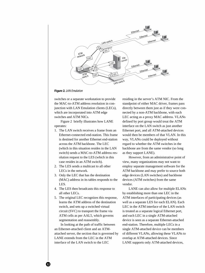
Figure 2 briefly illustrates how LANEoperates:1. The LAN switch receives a frame from an
Ethernet-connected end-station. This frameis destined for another Ethernet end-stationacross the ATM backbone. The LEC(which in this situation resides in the LANswitch) sends a MAC-to-ATM address res-olution request to the LES (which in thiscase resides in an ATM switch).
2. The LES sends a multicast to all otherLECs in the network.
3. Only the LEC that has the destination(MAC) address in its tables responds to theLES.
4. The LES then broadcasts this response toall other LECs.
5. The original LEC recognizes this response,learns the ATM address of the destinationswitch, and sets up a switched virtualcircuit (SVC) to transport the frame viaATM cells as per AAL5, which governssegmentation and reassembly.In looking at the path of traffic between
an Ethernet-attached client and an ATM-attached server, the section that is governed byLANE extends from the LEC in the ATMinterface of the LAN switch to the LEC
residing in the server’s ATM NIC. From thestandpoint of either MAC driver, frames passdirectly between them just as if they were con-nected by a non-ATM backbone, with eachLEC acting as a proxy MAC address. VLANsdefined by port group would treat the ATMinterface on the LAN switch as just anotherEthernet port, and all ATM-attached deviceswould then be members of that VLAN. In thisway, VLANs could be deployed withoutregard to whether the ATM switches in thebackbone are from the same vendor (so longas they support LANE).
However, from an administrative point ofview, many organizations may not want toemploy separate management software for theATM backbone and may prefer to source bothedge devices (LAN switches) and backbonedevices (ATM switches) from the samevendor.
LANE can also allow for multiple ELANsby establishing more than one LEC in theATM interfaces of participating devices (aswell as a separate LES for each ELAN). EachLEC in the ATM interface of the LAN switchis treated as a separate logical Ethernet port,and each LEC in a single ATM-attacheddevice is seen as a separate Ethernet-attachedend-station. Therefore, multiple LECs in asingle ATM-attached device can be membersof different VLANs, allowing these VLANs tooverlap at ATM-attached devices. SinceLANE supports only ATM-attached devices,
12
Figure 2. LAN Emulation
Ethernet
Ethernet
EthernetATMswitch
ATMnetwork
LAN switch
LAN switch
LESSVC
SVC
SVC
51 LEC
LEC42
LEC3
Fileserver
Ethernet
Ethernet
Ethernet
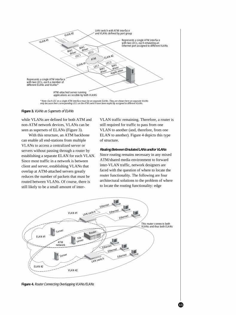
while VLANs are defined for both ATM andnon-ATM network devices, VLANs can beseen as supersets of ELANs (Figure 3).
With this structure, an ATM backbonecan enable all end-stations from multipleVLANs to access a centralized server orservers without passing through a router byestablishing a separate ELAN for each VLAN.Since most traffic in a network is betweenclient and server, establishing VLANs thatoverlap at ATM-attached servers greatlyreduces the number of packets that must berouted between VLANs. Of course, there isstill likely to be a small amount of inter-
VLAN traffic remaining. Therefore, a router isstill required for traffic to pass from oneVLAN to another (and, therefore, from oneELAN to another). Figure 4 depicts this typeof structure.
Routing Between Emulated LANs and/or VLANsSince routing remains necessary in any mixedATM/shared media environment to forwardinter-VLAN traffic, network designers arefaced with the question of where to locate therouter functionality. The following are fourarchitectural solutions to the problem of whereto locate the routing functionality: edge
13
Figure 3. VLANs as Supersets of ELANs
LEC1
LEC2
MAC driver
MACdriver
ELAN #1
ELAN #2
VLAN #2
VLAN #1
LEC1
LEC2MAC driver
MACdriver
ATM
Application
LAN switch with ATM interface and VLANs defined by port group
Represents a single ATM interface with two LECs, each emulating an Ethernet port assigned to different VLANs
Represents a single ATM interface with two LECs, each a member of different ELANs and VLANs*
ATM-attached server running applications accessible by both VLANS
* Note: Each LEC on a single ATM interface must be on separate ELANs. They are shown here on separate VLANs only because their corresponding LECs on the ATM switch have been explicitly assigned to different VLANs.
Figure 4. Router Connecting Overlapping VLANs/ELANs
Fileserver
Ethernet
Ethernet
EthernetLAN switch
Ethernet
Ethernet
Ethernet
LAN switch
Server
Server
VLAN #1
ELAN #1
ATM network
VLAN #2ELAN #2
This router connects both VLANs and thus both ELANs
Router
routing, the “one-armed” router, the routeserver, and MPOA.
Edge Routing. Basically, edge routing dictatesthat the routing function across the ATMbackbone be incorporated into each LANswitch at the “edge” of the ATM backbone.Traffic within VLANs can be switched acrossthe ATM backbone with minimal delay, whileinter-VLAN packets are processed by therouting function built into the switch. In thisway, an inter-VLAN packet does not have tomake a special trip to an external router, elimi-nating a time-consuming extra hop.
There are three other major advantages tothis architecture. First, unlike solutions thathave centralized routing, there is no singlepoint of failure with edge routing architectures.Second, several solutions featuring edgerouting are available today. Third, edge routingwill function in multivendor environments ifeach vendor’s equipment supports LANEmulation.
The primary disadvantage of edge routingis the difficulty of managing multiple physicaldevices relative to having centralized man-agement of a consolidated router/routingfunction. Additionally, edge routing solutionsmay be more expensive than centralized routingsolutions made up of a centralized router andmultiple, less-expensive edge switches.
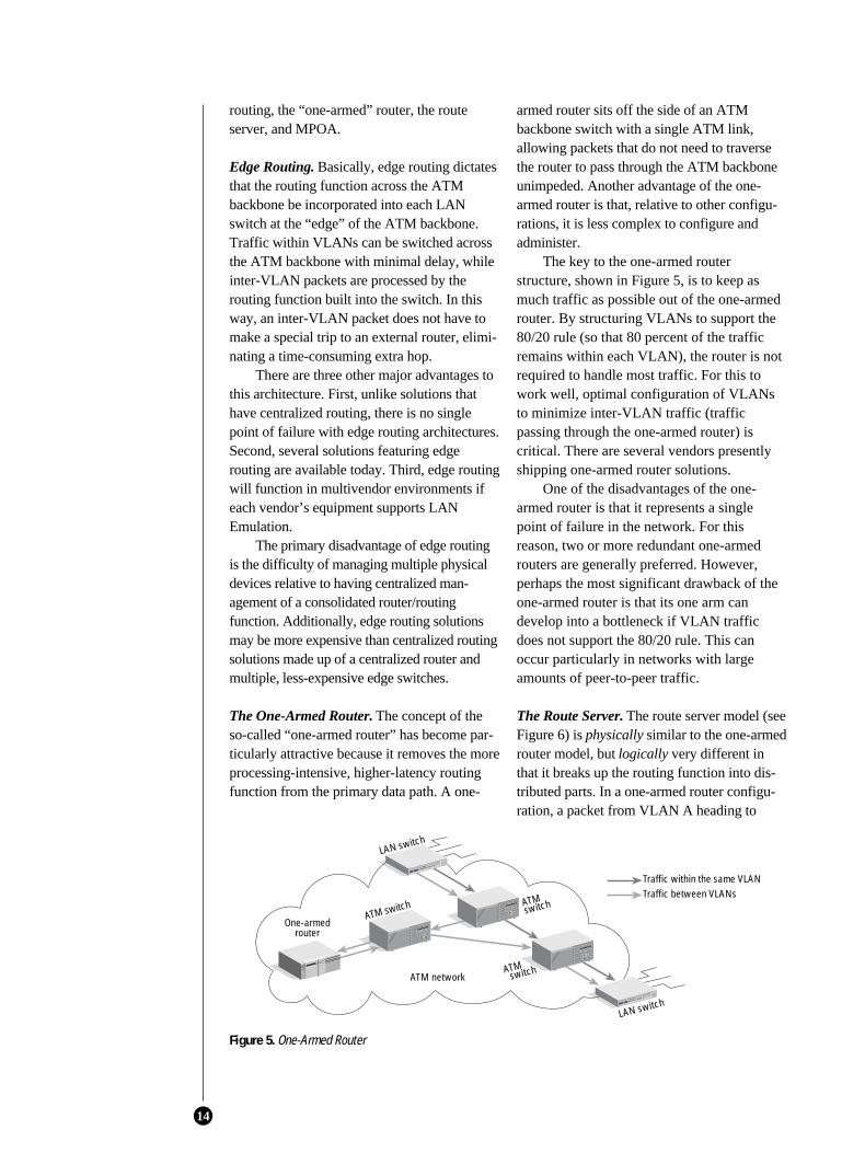
The One-Armed Router. The concept of theso-called “one-armed router” has become par-ticularly attractive because it removes the moreprocessing-intensive, higher-latency routingfunction from the primary data path. A one-
armed router sits off the side of an ATMbackbone switch with a single ATM link,allowing packets that do not need to traversethe router to pass through the ATM backboneunimpeded. Another advantage of the one-armed router is that, relative to other configu-rations, it is less complex to configure andadminister.
The key to the one-armed routerstructure, shown in Figure 5, is to keep asmuch traffic as possible out of the one-armedrouter. By structuring VLANs to support the80/20 rule (so that 80 percent of the trafficremains within each VLAN), the router is notrequired to handle most traffic. For this towork well, optimal configuration of VLANsto minimize inter-VLAN traffic (trafficpassing through the one-armed router) iscritical. There are several vendors presentlyshipping one-armed router solutions.
One of the disadvantages of the one-armed router is that it represents a singlepoint of failure in the network. For thisreason, two or more redundant one-armedrouters are generally preferred. However,perhaps the most significant drawback of theone-armed router is that its one arm candevelop into a bottleneck if VLAN trafficdoes not support the 80/20 rule. This canoccur particularly in networks with largeamounts of peer-to-peer traffic.
The Route Server. The route server model (seeFigure 6) is physically similar to the one-armedrouter model, but logically very different inthat it breaks up the routing function into dis-tributed parts. In a one-armed router configu-ration, a packet from VLAN A heading to
14
Figure 5. One-Armed Router
LAN switch
ATM network
One-armed router
LAN switch
Traffic within the same VLANTraffic between VLANs
ATM switch
ATM switch
ATMswitch
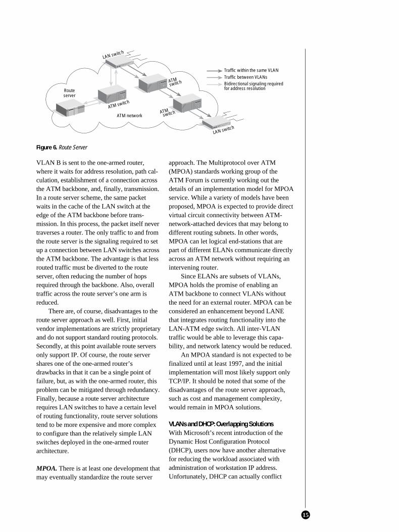
VLAN B is sent to the one-armed router,where it waits for address resolution, path cal-culation, establishment of a connection acrossthe ATM backbone, and, finally, transmission.In a route server scheme, the same packetwaits in the cache of the LAN switch at theedge of the ATM backbone before trans-mission. In this process, the packet itself nevertraverses a router. The only traffic to and fromthe route server is the signaling required to setup a connection between LAN switches acrossthe ATM backbone. The advantage is that lessrouted traffic must be diverted to the routeserver, often reducing the number of hopsrequired through the backbone. Also, overalltraffic across the route server’s one arm isreduced.
There are, of course, disadvantages to theroute server approach as well. First, initialvendor implementations are strictly proprietaryand do not support standard routing protocols.Secondly, at this point available route serversonly support IP. Of course, the route servershares one of the one-armed router’sdrawbacks in that it can be a single point offailure, but, as with the one-armed router, thisproblem can be mitigated through redundancy.Finally, because a route server architecturerequires LAN switches to have a certain levelof routing functionality, route server solutionstend to be more expensive and more complexto configure than the relatively simple LANswitches deployed in the one-armed routerarchitecture.
MPOA. There is at least one development thatmay eventually standardize the route server
approach. The Multiprotocol over ATM(MPOA) standards working group of theATM Forum is currently working out thedetails of an implementation model for MPOAservice. While a variety of models have beenproposed, MPOA is expected to provide directvirtual circuit connectivity between ATM-network-attached devices that may belong todifferent routing subnets. In other words,MPOA can let logical end-stations that arepart of different ELANs communicate directlyacross an ATM network without requiring anintervening router.
Since ELANs are subsets of VLANs,MPOA holds the promise of enabling anATM backbone to connect VLANs withoutthe need for an external router. MPOA can beconsidered an enhancement beyond LANEthat integrates routing functionality into theLAN-ATM edge switch. All inter-VLANtraffic would be able to leverage this capa-bility, and network latency would be reduced.
An MPOA standard is not expected to befinalized until at least 1997, and the initialimplementation will most likely support onlyTCP/IP. It should be noted that some of thedisadvantages of the route server approach,such as cost and management complexity,would remain in MPOA solutions.
VLANs and DHCP: Overlapping SolutionsWith Microsoft’s recent introduction of theDynamic Host Configuration Protocol(DHCP), users now have another alternativefor reducing the workload associated withadministration of workstation IP address.Unfortunately, DHCP can actually conflict
15
Figure 6. Route Server
LAN switch
ATM network
Route server
LAN switch
Traffic within the same VLANTraffic between VLANs
ATM switch
ATM switch
ATMswitch Bidirectional signaling required
for address resolution
with VLAN implementation, especially withlayer-3, IP-based VLANs.
DHCP FunctionalityWhen considering the ability of VLANs todeal with ever-changing networks, it should beremembered that most of the difficulty in sup-porting adds, moves, and changes occurs in IPnetworks. In order to deal with the problem ofreconfiguring IP addresses, Microsoft hasdeveloped DHCP, a TCP/IP-based solutionincorporated into the Windows NT™ serverand most Windows® clients.
Rather than establishing location-inde-pendent broadcast domains as VLANs do,DHCP dynamically allocates IP addresses tological end-stations for fixed periods of time.When the DHCP server detects a workstationwhose physical location no longer corre-sponds to its allocated IP address, it simplyallocates that end-station a new address. Bydoing so, DHCP enables workstations to bemoved from subnet to subnet without thenetwork administrator having to manuallyconfigure the workstation’s IP address orupdate host table information.
The element of DHCP that equates mostclosely to VLAN functionality is the networkadministrator’s ability to specify a range of IPaddresses available for a particular logicalworkgroup. These logical groups are termed“scopes” in the Microsoft lexicon. However,scopes should not be equated with VLANs,because members of a single scope are stillbound by their physical subnet, although therecan be multiple scopes residing in each subnet.Consequently, DHCP implementation mayreduce the labor-intensive administration ofTCP/IP networks, but DHCP alone does notcontrol network broadcasts in the same waythat VLANs do.
Best Use for EachIn what types of network environments shouldVLANs be implemented, and in what types ofnetwork environments does DHCP make themost sense? Since DHCP is solely an IP-basedsolution, it has little appeal in environmentswhere IP users are a minority, since all non-TCP/IP clients would be excluded from scopemembership. In particular, network envi-
ronments where non-TCP/IP protocols arerequired for mission-critical applications maybenefit more from VLAN implementation,since VLANs can be used to contain multi-protocol broadcast traffic.
However, for smaller, purely TCP/IPnetwork environments (under 500 nodes),DHCP alone may suffice. By simply havingfewer total network nodes and fewer physicalsubnets, the need to establish fully location-independent logical groups is greatlyreduced. Additionally, for medium-sizedorganizations that, for whatever reason, donot support location-independent work-groups, VLANs lose much of their appealwhen compared to DHCP.
There is one area in which VLANs andDHCP do not compete: reducing the necessityfor routing in the network. Although DHCPservers dynamically maintain address tables,they lack routing functionality and cannotcreate broadcast domains. Therefore, DHCPhas no impact on an organization’s need forrouting in the network. In environments wherethe containment of broadcast traffic withouthaving to resort to routers is a majorrequirement, VLANs are a better solution.
Overlap Between DHCP and VLANsIt what ways can DHCP and VLANs worktogether, and in what situations do they rep-resent competitive solutions?
DHCP and layer-3, IP-based VLANsclearly represent competitive solutionsbecause of addressing problems that stemfrom implementing layer 3–based VLANs inconjunction with DHCP. If a client work-station physically moves to a new subnet, theDHCP server will allocate a new IP addressfor that workstation. Yet, this workstation’sVLAN membership is based on the old IPaddress. Therefore, the network administratorwould have to manually update the client’s IPaddress in the switch’s VLAN tables. Thiswould eliminate the primary benefit of DHCPand one of the primary benefits of IP-basedVLANs. In summary, these two solutions rep-resent an either/or proposition for mostnetwork environments.
Implementing VLANs defined by MAC-layer address in conjunction with DHCP is a
16
somewhat more plausible solution. However,DHCP together with MAC-based VLANswould create a two-tiered, redundant matrix oflogical groups (MAC address–based VLANsand DHCP scopes). Having two tiers of logicalgroups would make otherwise easy-to-manage,“drag-and-drop” moves, adds, and changesunnecessarily difficult and might entail morelabor-intensive network administration than ifneither solution was implemented.
Port group–based VLANs and DHCP cancoexist, and their joint implementation caneven be complementary. As stated earlier,when users in VLANs based purely on portgroups move from one port group to another,their VLAN membership changes. In a non-DHCP environment where IP subnets cor-respond one-to-one with VLANs, users whomove from one port group to another wouldstill need to have their workstation recon-figured to reflect their new IP subnet.Implementing DHCP would make this recon-figuration automatic. The port group–basedVLANs, of course, provide the broadcast con-tainment that DHCP implementation alonedoes not. In this way, DHCPand port-group-basedVLANs can work togetherto accomplish bothbroadcast containment andautomation of moves andchanges.
Port group–basedVLANs and DHCP, in con-junction with deployment ofarchitectures that reduce theneed for external routing ofinter-VLAN traffic (such asmultiple VLAN memberhipor integrating routing intothe switch), represent afairly complete short- to medium-termsolution, which will alleviate the most pressingproblems faced in many network envi-ronments.
VLAN Architectures Going ForwardDue to the trends toward server centralization,enterprise-wide e-mail, and collaborativeapplications, various network resources will
need to be made available to users regardlessof their VLAN membership. Ideally, thisaccess should be provided without most usertraffic having to traverse a router.
Organizations that implement VLANs rec-ognize the need for certain logical end-stations(for example, centralized servers) to commu-nicate with multiple VLANs on a regular basis,either through overlapping VLANs (in whichnetwork-attached end-stations simultaneouslybelong to more than one VLAN) or via inte-grated routing that can process inter-VLANpackets at wire speed. From a strategicstandpoint, these organizations have two waysto deploy VLANs: an “infrastructural” VLANimplementation or a “service-based” VLANimplementation. The choice of approach willhave a substantial impact on the overallnetwork architecture, and may even affect themanagement structure and business model ofthe organization.
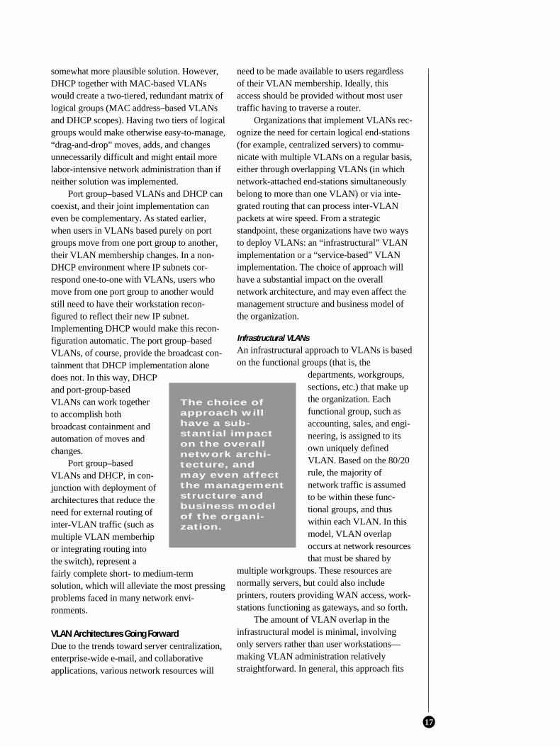
Infrastructural VLANsAn infrastructural approach to VLANs is basedon the functional groups (that is, the
departments, workgroups,sections, etc.) that make upthe organization. Eachfunctional group, such asaccounting, sales, and engi-neering, is assigned to itsown uniquely definedVLAN. Based on the 80/20rule, the majority ofnetwork traffic is assumedto be within these func-tional groups, and thuswithin each VLAN. In thismodel, VLAN overlapoccurs at network resourcesthat must be shared by
multiple workgroups. These resources arenormally servers, but could also includeprinters, routers providing WAN access, work-stations functioning as gateways, and so forth.
The amount of VLAN overlap in theinfrastructural model is minimal, involvingonly servers rather than user workstations—making VLAN administration relativelystraightforward. In general, this approach fits
17
The choice ofapproach willhave a sub-stantial impacton the overallnetwork archi-tecture, andmay even affectthe managementstructure andbusiness modelof the organi-zation.
well in those organizations that maintain clean,discrete organizational boundaries. The infra-structural model is also the approach mosteasily enabled by presently available solutionsand fits more easily with networks deployedtoday. Moreover, this approach does notrequire network administrators to alter howthey view the network, and entails a lower costof deployment. For these reasons, most organi-zations should begin with an infrastructuralapproach to VLAN implementation.
As can be seen in the example in Figure 7,the e-mail server is a member of all of thedepartments’ VLANs, while the accountingdatabase server is only a member of theaccounting VLAN.
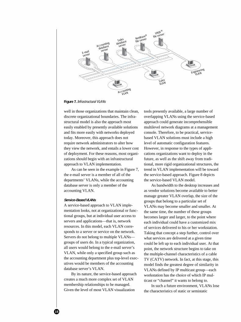
Service-Based VLANsA service-based approach to VLAN imple-mentation looks, not at organizational or func-tional groups, but at individual user access toservers and applications—that is, networkresources. In this model, each VLAN corre-sponds to a server or service on the network.Servers do not belong to multiple VLANs—groups of users do. In a typical organization,all users would belong to the e-mail server’sVLAN, while only a specified group such asthe accounting department plus top-level exec-utives would be members of the accountingdatabase server’s VLAN.
By its nature, the service-based approachcreates a much more complex set of VLANmembership relationships to be managed.Given the level of most VLAN visualization
tools presently available, a large number ofoverlapping VLANs using the service-basedapproach could generate incomprehensiblemultilevel network diagrams at a managementconsole. Therefore, to be practical, service-based VLAN solutions must include a highlevel of automatic configuration features.However, in response to the types of appli-cations organizations want to deploy in thefuture, as well as the shift away from tradi-tional, more rigid organizational structures, thetrend in VLAN implementation will be towardthe service-based approach. Figure 8 depictsthe service-based VLAN model.
As bandwidth to the desktop increases andas vendor solutions become available to bettermanage greater VLAN overlap, the size of thegroups that belong to a particular set ofVLANs may become smaller and smaller. Atthe same time, the number of these groupsbecomes larger and larger, to the point whereeach individual could have a customized mixof services delivered to his or her workstation.Taking that concept a step further, control overwhat services are delivered at a given timecould be left up to each individual user. At thatpoint, the network structure begins to take onthe multiple-channel characteristics of a cableTV (CATV) network. In fact, at this stage, thismodel finds the greatest degree of similarity inVLANs defined by IP multicast group—eachworkstation has the choice of which IP mul-ticast or “channel” it wants to belong to.
In such a future environment, VLANs losethe characteristics of static or semistatic
18
Figure 7. Infrastructural VLANs
server
Accounting
database
server
Sales
database
server
NetWare
file server
UNIX
file server
Accounting
VLAN
SalesVLAN
Engineering
VLAN
®
®
broadcast domains defined by the networkmanager, and become channels to which userssubscribe. Users simply sign up for the appli-cations they need delivered to them at a par-ticular time. Application use could beaccounted for, enabling precise and automatedchargeback for network services. Networkmanagers could also retain control in order toblock access to specific channels by certainusers for security purposes.
VLAN Migration StrategiesAs this paper has demonstrated, there aremany factors to be considered in VLANimplementation: technological, architectural,and organizational. Given the effects ofVLANs on network architecture, organiza-tional structure, and even the business modelof some organizations, it is difficult to deployVLAN technology solely as a tactical solution,only where and when it is needed. However,this does not imply an all-or-nothing strategyin which the network architecture is trans-formed overnight from one based on physicalsubnets and router-based segmentation to oneof service-based VLANs.
What steps are necessary before applyingVLANs to an enterprise network? Initially,VLANs should be seen as a solution to at leastone of two problems:• Containment of broadcast traffic to
minimize dependence on routers• Reduction in the cost of network moves and
changes
An organization where broadcast traffic isnot yet a problem, or where the cost ofnetwork moves and changes is tolerable, maywant to forgo implementing VLANs for thetime being. However, the majority of largeenterprise networks are now experiencing oneor both of these problems.
In organizations that are rapidly replacingrouters with switches and may soon facebroadcast traffic containment issues, anotherelement of the network architecture should beconsidered: the degree to which the networkhas evolved toward a single user/port switchedLAN architecture. If the majority of users arestill on shared LAN segments, the ability ofVLANs to contain broadcasts is greatlyreduced. If multiple users belonged to differentVLANs on the same shared LAN segment,that segment would receive broadcasts fromeach VLAN—defeating the goal of broadcastcontainment.
Having determined that VLANs need tobe a part of network planning in the immediatefuture, server access, server location, andapplication utilization must all be thoroughlyanalyzed to determine the nature of traffic flowin the network. This analysis should answerthe remaining questions about where VLANbroadcast domains should be deployed, whatrole ATM needs to play, and where the routingfunction should to be placed.
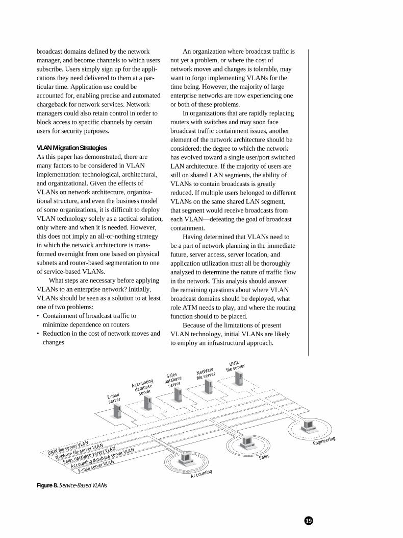
Because of the limitations of presentVLAN technology, initial VLANs are likelyto employ an infrastructural approach.
19
Figure 8. Service-Based VLANs
server
Accounting
database
server
Sales
database
server
NetWare
file server
UNIX
file server
Accounting
Sales
Engineering
Sales database server VLAN
Accounting database server VLAN
E-mail server VLANNetWare file server VLAN
UNIX file server VLAN
However, as vendor solutions develop, manyorganizations will want to consider migrationtoward a more service-based model, whichwill more easily let users subscribe to variousnetwork services.
This concept of user-controlled sub-scribership, as opposed to administrator-con-trolled membership, is augmented by NICswith built-in VLAN functionality operating inenvironments with a single user per switchport. In this scheme, the NIC driver dynam-ically tells the switch which multicast groupsor VLANs it wants to belong to. Certainly, thistype of distributed VLAN control leverages theincreasing processing power of the desktopand enables a higher degree of other, relatedfunctionality such as automatic VLAN config-uration and traffic monitoring. In addition,agents residing in each NIC will enable theworkstation to collect and report informationon specific application usage (rather than justsimple layer 2 traffic statistics in the case ofRMON1). This capability facilitates theautomated chargeback for network servicesdescribed earlier for service-based VLANs.
If individual users control VLAN mem-bership, what about security? Clearly, userscannot be allowed to simply subscribe to anynetwork service they wish. The networkadministrator must be able to establish policiesthat define which users have access to whatresources and what class of service each user isentitled to. One solution to the securityproblem may come in the form of an authenti-cation server. These servers may well developinto the primary method by which the VLANsof the future are defined. Authenticationservers define VLAN membership by user ID(password or other authentication device)rather than by MAC address or IP address.Defining VLANs in this way greatly increasesflexibility and also implies a certain level ofintegration of VLANs with the networkoperating system, which typically asks the userfor a password anyway to allow or deny accessto network resources. One of the primaryadvantages of authentication servers is that
they allow the user to take his or her VLANanywhere, without regard to which workstationor protocol is being used.
The analysis of network traffic, appli-cations usage, server access, and so on that isnecessary in the VLAN migration process, andwhich will be greatly furthered by the imple-mentation of RMON2, may simply produceVLANs that correspond to functional teams ordepartments. On the other hand, if migration isundertaken with a holistic view of the capa-bilities of VLAN technology, and the networkdesigners ask the question, “Who should talkto whom?” rather than “Who is talking towhom?,” it may become apparent that funda-mental process and organizational changes areneeded. Many organizations are making suchchanges: trends such as flatter hierarchies,revamped workflows, and innovative businessmodels are helping to fully leverage the possi-bilities of emerging applications.
ConclusionThe concept of service-based VLAN tech-nology holds the potential for harmonizingmany of today’s organizational and managerialchanges with the structural and technologicaldevelopments in the network. Despite thepromise of this vision, VLAN implementationmust solve real-world problems in order to befinancially justified. Organizations that havedeployed or are planning to deploy largenumbers of switch ports, dividing the networkinto smaller segments to increase bandwidthper user, can make a very strong case forVLAN implementation in order to containbroadcasts. However, any organization thatexpends substantial resources dealing withmoves and changes in the network may also beable to justify VLAN implementation. This issimply because VLANs, if implemented aspart of a strategic solution, may be able to sub-stantially reduce the cost of dealing withmoves and changes. For these organizations,the switching infrastructure upon which mostVLAN solutions are based can be seen as anadded, and quite valuable, benefit.
20

Printed in U.S.A. 200374-001 5/96
AppleTalk is a trademark of Apple Computer. DECnet is a trademark of Digital Equipment Corporation. Lotus Notes is a trademark of Lotus Development Corporation. Windows and Windows NT are trademarks of Microsoft.IPX and NetWare are trademarks of Novell. UNIX is a trademark of UNIX Laboratories.