Embed Size (px)
Citation preview

10/15/2016
1
THE WEARABLE THERMAL GENERATOR: A BATTERY FREE POWER SUPPLYPRESENTED BY: NATE BEEMER
ADVISOR: PROF. HAL BROBERG
INSTRUCTOR: PROF. PAUL LIN
5/1/2015
1
OUTLINE:
• Executive Summary
• Introduction
• Problem and Solution
• System Requirements and Validation
• System Analysis
• System Design
• System Integration and Testing
• Conclusion
• Demo/Q & A 2

10/15/2016
2
EXECUTIVE SUMMARY
• The Wearable Thermal Generator project sought to build a prototype for an
affordable apparatus that would generate power in cool, dark environments
with some ambient wind by harnessing only the waste heat dissipated from
the human body. The power generated could then be used to power efficient
light emitting diodes (LEDs), charge cell phones, or be stored in a
rechargeable battery pack for future use.
3
INTRODUCTION
• This project consisted of a plan for the design, construction, and testing of a
wearable thermoelectric generating device. It was the hopes of the designer
that this project would inspire others to look into other ways of utilizing
alternate sources of power in everyday life.
4

10/15/2016
3
PROBLEM AND SOLUTION
“Where there’s a need, there’s a niche in the market.”
-Me
5
SO WHY?
• Typical AA weighs between 15-31g
• Spelunkers carry at least 12 AA’s per headlamp (usually 3 lamps)
• Average person throws away 8 non-rechargeable batteries / year
• All mobile devices rely on batteries
6

10/15/2016
4
GO ON… I’M LISTENING…
• By the end of 2015, the estimated market for lithium-ion batteries alone will
reach almost 13.2 billion U.S. dollars
• Several ways to recharge batteries…
• Consider that a Samsung Galaxy S4 phone can last ~1,051 minutes making a
call or ~405 minutes using the internet
• Duration plays key role in purchases
7
SO THAT MEANS…
• A need exists for a device that can help recharge portable electronics when
no other alternate energy source is available
• Potential market
• Cut down on chemical waste
• Lighter and longer
8

10/15/2016
5
SYSTEM REQUIREMENTS AND VALIDATION
• Wearable
• Operates in 70o F max (with some ambient air)
• Generates enough power to light an LED
• Ability to charge batteries / portable devices
9
SYSTEM ANALYSIS
10

10/15/2016
6
SYSTEM ANALYSIS CONT.
11
SYSTEM ANALYSIS CONT.
12

10/15/2016
7
SYSTEM ANALYSIS CONT.
13
Combined surface area of TEG units: 8cm x 8cm = 64cm2
Average power dissipated by humans: ~97 Watts
Average surface area of human skin: 1.7m2 or 17,000cm2
Average power dissipated per cm2 of human skin: 97
17,000 2 x 1000 = 5.7
2
Power expected to be generated by total area of TEG units: 5.7
2 x 64cm2 = 364.8mW
With 10% TEG efficiency, actual power expected to be generated by the total area of the TEG units: (364.8 mW) x (0.1) = 36.48 mW
Target voltage generated from TEG units: ~50mV DC
Target current generated from TEG units: 36.48
50 = 0.73A
SYSTEM ANALYSIS CONT.
140
20
40
60
80
100
120
140
160
0
20
40
60
80
100
120
140
160
180
200
220
240
260
280
300
320
340
360
380
400
420
440
460
480
500
520
540
560
580
600
620
640
660
680
700
720
740
760
780
800
820
840
860
880
900
Potential (mv)
Time (seconds)
Decay Rate
ARM
THIGH
NECK
NECK

10/15/2016
8
SYSTEM ANALYSIS CONT.
15
SYSTEM ANALYSIS CONT.
16

10/15/2016
9
SYSTEM ANALYSIS CONT.
17
SYSTEM ANALYSIS CONT.
18

10/15/2016
10
SYSTEM ANALYSIS CONT.
19
SYSTEM ANALYSIS CONT.
20
0
0.02
0.04
0.06
0.08
0.1
0.12
0.14
0.16
2.4
62
2.1
44
1.8
26
1.5
81
.18
10
0.8
61
20
.54
14
0.2
21
59
.91
79
.58
19
9.2
62
18
.94
23
8.6
22
58
.32
77
.98
29
7.6
63
17
.34
33
7.0
23
56
.73
76
.38
39
6.0
64
15
.74
43
5.4
24
55
.14
74
.78
49
4.4
65
14
.14
53
3.8
25
53
.55
73
.18
59
2.8
66
12
.54
63
2.2
26
51
.96
71
.58
69
1.2
67
10
.94
73
0.6
27
50
.37
69
.98
78
9.6
68
09
.34
82
9.0
28
48
.78
68
.38
88
8.0
69
07
.74
92
7.4
29
47
.19
66
.78
98
6.4
61
00
6.1
41
02
5.8
21
04
5.5
10
65
.18
10
84
.86
11
04
.54
11
24
.22
11
43
.91
16
3.5
81
18
3.2
6
Vol
tage
(m
V)
Time (seconds)
Refined LabVIEW Arm TestVoltage vs. Time

10/15/2016
11
SYSTEM ANALYSIS CONT.
21
0
0.02
0.04
0.06
0.08
0.1
0.12
0.14
0.16
2.3
20
.73
9.1
57
.57
5.9
94
.31
12
.71
31
.11
49
.51
67
.91
86
.32
04
.72
23
.12
41
.52
59
.92
78
.32
96
.73
15
.13
33
.53
51
.93
70
.33
88
.74
07
.14
25
.54
43
.94
62
.34
80
.74
99
.15
17
.55
35
.95
54
.35
72
.75
91
.16
09
.56
27
.96
46
.36
64
.76
83
.17
01
.57
19
.97
38
.37
56
.77
75
.17
93
.58
11
.98
30
.38
48
.78
67
.18
85
.59
03
.99
22
.39
40
.79
59
.19
77
.59
95
.91
01
4.3
10
32
.71
05
1.1
10
69
.51
08
7.9
11
06
.31
12
4.7
11
43
.11
16
1.5
11
79
.91
19
8.3
Vol
tage
(m
V)
Time (seconds)
Refined LabVIEW Cranial (Temple) TestVoltage vs. Time
SYSTEM ANALYSIS CONT.
22

10/15/2016
12
SYSTEM DESIGN
23
V1
4 V 0.1 Ω
V212 V
T2C2
1nF
C3
470pF
C447µF
C52.2µF
U1
LTC3109
12345678910 11
121314151617181920
Q1
BST100
U2
LTC4070
1234 5
678
C6
47µF
C7
200µF10%
S2
C8
1nFC9
470pF
T1
V312 V
V412 V
V512 V
LED1
SYSTEM DESIGN CONT.
24
C2
1nF
C3
470pF
C447µF
C52.2µF
U1
LTC3109
12345678910 11
121314151617181920
Q1
BST100
U2
LTC4070
1234 5
678
C6
47µF
C7
200µF10%
C8
1nFC9
470pF
U3pinsocket
12
U4pinsocket
12
U5pinsocket
12
U6pinsocket
12
U7pinsocket
12
U8
pinsocket
12
U9dipswtich
1 2 3 4 5 6 7 8910111213141516
U10
transformer
12 3
4
U11
transformer
12 3
4

10/15/2016
13
SYSTEM DESIGN CONT.
25
SYSTEM DESIGN CONT.
26

10/15/2016
14
SYSTEM DESIGN CONT.
27
SYSTEM DESIGN CONT.
28

10/15/2016
15
SYSTEM DESIGN CONT.
• First prototype breakout boards failed to work
• Cut circuit board wouldn’t have worked anyway, due to transformer glitch
• Back to the drawing board…
29
SYSTEM DESIGN CONT.
30
10/15/2016
16
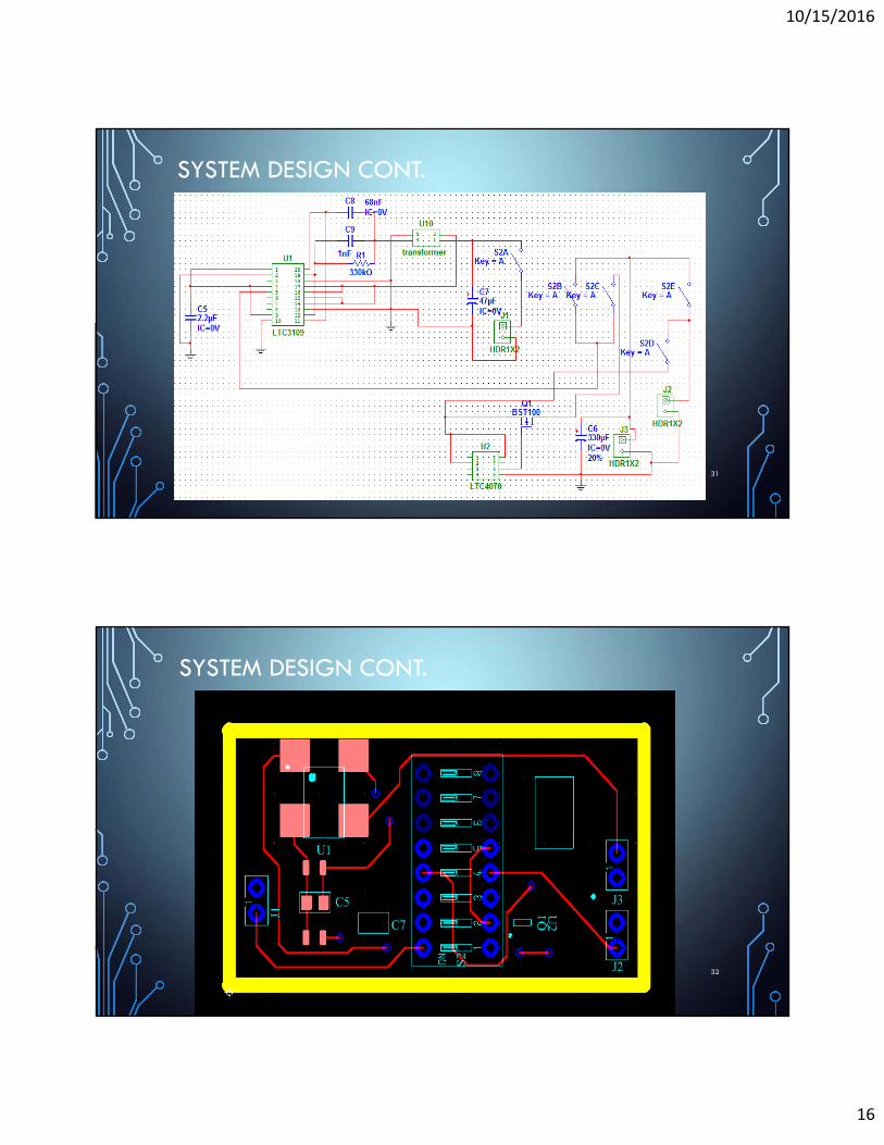
SYSTEM DESIGN CONT.
31
SYSTEM DESIGN CONT.
32

10/15/2016
17
SYSTEM DESIGN CONT.
33
SYSTEM DESIGN CONT.
34

10/15/2016
18
SYSTEM DESIGN CONT.
35
SYSTEM DESIGN CONT.
• Hand-soldered transformers to the circuit board…
• It worked!
36

10/15/2016
19
SYSTEM INTEGRATION AND TESTING
37
SYSTEM INTEGRATION AND TESTING CONT.
38

10/15/2016
20
SYSTEM INTEGRATION AND TESTING CONT.
39
SYSTEM INTEGRATION AND TESTING CONT.
40

10/15/2016
21
SYSTEM INTEGRATION AND TESTING CONT.
41
CONCLUSION
• Prototype succeeded in producing enough voltage to power a 1-
Watt, CREE LED
• One prototype could produce a sustained 3.3V, ~1mA at 70oF,
while the other prototype could produce a sustained 5V, ~1mA at
70oF
• Power needs lasted well beyond 20 minutes in proper conditions
• Further testing needed to determine whether trickle-charger circuit
works42

10/15/2016
22
CONCLUSION CONT.
• Future designs might include head-mounted systems, piezoelectric
power sources, and water-proof circuitry
• Ideas for start-up business? Kickstarter campaign?
43
DEMO / Q & A
44


![Wearable [REDACTED]](https://img.pdfslide.net/doc/110x75/559f58221a28abf0078b482f/wearable-redacted.jpg)