Embed Size (px)
Citation preview

The Weber Sandstone at Rangely Field
Fact Book
Kent Bowker

The Weber Sandstone at Rangely Field, Colorado1
j
1
I
I
I I I
I I
I i i
i i
j
1
I i
I
i i i i i i
! I i i I I I I
I I
I
I I I I I I i I
!
! 1
!
j
i
j
j
I
I
KENT A. BOWKER2 WILLIAM D. JACKSON3
‘Received August 15, 1988; Revised April 4, 1989 %hevron U.S.A. Inc., New Orleans, Louisiana %hevron U. S, A. Inc., Houston, Texas
The Permo-Pennsylvanian Weber Sandstone is the major producing horizon at the giant Rangely Field, Rio Blanco County, Colorado. The Weber is separated into three major lithotypes, the distribution of which is related to depositional environment. The Weber was deposited in two major depositional environments: fluvial and eolian. The fluvial deposits, derived fiom the ancestral Uncompahgre Uplift, are dominantly arkosic sandstones, siltstones, and shales. The arkosic lithofacies are not productive and act as intraformational permeability barriers. The eolian sediments were deposited in dune, interdune, and extradune environments as j?ne and very $ne-grained subarkosic sand. They are either cross laminated (mostly wind- ripple laminae) or massively bedded (bioturbated) . The cross-laminated lithofacies is the major productive Eithofacies, with an average porosity of 12%. Permeability is highly direc- tional on a small scale because of differential cementation related to grain sizes within inverse- graded laminae. Permeability along the laminae averages 2 md; permeability across the lami- nae averages 0.4 md. Massive sandstone has a mean porosity of 7.1% and mean permeability of 0.2 md.
The Raven Park Anticline provides the trap at Rangely. One major normal fault and several minor normal faults affect hydrocarbon production by displacing productive zones between injection and production wells, and by acting as water and carbon dioxide conduits or thief zones.
In the diagenetic history of the Weber, much of the original porosity was destroyed by early and late cementation, although some was subsequently restored by dissolution of detrital and authigenic minerals. Asphaltene, which appears as moveable oil on wireline logs, was precipi- tated near the end of diagenesis.
The Weber reservoir initially was water wet, with a water saturation of 27.5%; the current carbon dioxide flood could be altering wettability. The carbon dioxide flood should boost ultimate recovery from the Weber to 900,000,000 BO.
INTRODUCTION The objective of this paper is to describe each of
the three major lithotypes identified in the Permo- Pennsylvanian Weber Sandstone, emphasizing those petrophysical characteristics that affect oil and gas production. Core descriptions, core analyses, optical and scanning electron microscopy (SEM) , and x-ray diffraction (XRD) and special core analyses were used to separate the Weber into three major lithotypes. Distribution of these lithotypes is controlled by deposi- tional environments and is the major influence on hy- drocarbon production in the field.
The giant Rangely Field (Fig. l ) , in Rio Blanco County, Colorado, is one of the largest oil fields in the Rocky Mountain region, covering approximately
Sandstone Reservoirs-1989
19,000 acres (7,689 ha) (Fig. 2). It lies at the north- ern end of the Douglas Creek Arch, which separates the Uinta and Piceance basins. Rangely Field is by far the largest of a trend of Weber Sandstone fields found along the northern Piceance Basin.
Petroleum migrated into the region during the Mesozoic, b’efore the Late Cretaceous-Early Tertiary Laramide Orogeny (Campbell, 1955; Fryberger, 1979). Oil may have been trapped against imperme- able Maroon rocks all along the southern terminus of Weber deposition. Asphaltene found in sandstones throughout the region may have precipitated at that time.
Shallow production from the Cretaceous Mancos Group shales was established at Rangely from 1901
65 Rocky Mountain Association of Geologists
Bluescape Page 1 of 18 12/31/2009

Bowker and Jackson
FIELD DATA: Producing Interval: Geographic Location: Present Tectonic Setting: Depositional Setting: Age of Reservoir: Lithology of Reservoir: Depositional Environment: Diagenesis:
Porosity Types: Porosity: Permeability: Fractures: Nature of Trap: Entrapping Facies: ' Source Rock: Timing of Migration: Discovered: Reservoir Depth: Reservoir Thickness: IP (discovery well): Areal Extent: Original Reservoir Pressure: Cumulative Production (6/88): Estimated Oil in Place: Approximate Ultimate Recovery: Oil Gravity: Water Saturation: Sulfur Content:
Rangely Field Weber Sandstone Centered in T2N R102W; Rio Blanco County, Colorado Northwest edge of Piceance Basin Edge of sand sea, near margin of Uncompahgre fluvial system Permo-Pennsylvanian Subarkosic sandstone Erg and erg margin Quartz, carbonate and clay cementation; dissolution of feldspars and car- bonates; precipitation of asphaltene Primarily intergranular and secondary, with some intragranular and fracture Maximum 25%; average 12% Maximum 200 md; average 2 md Both local and extensive fractures Anticlinal closure Tight siltstones and shales of the Permian State Bridge Formation Permian Phosphoria Formation(?) Jurassic or later 1933 (Weber production; Mancos production found earlier) Average 6,500 ft (1,980 m) Average net 275 ft (84 m); average gross 650 ft (200 m) F 229 BOPD 19,153 acres (7,751 ha) 2,750 psi 722,000,000 BO, 4.10 BCFG 1,578,000,000 BO 939,000,000 BO, 5.30 BCFG 34" API Minimum 27.5% 0.7%
through 1933. Oil from the Weber Sandstone was discovered by the California Oil Company (Chevron) in 1933 with the drilling of the No. A-1 Raven (Sec 30 T2N R102W). Because of the remoteness of the discovery, development did not begin until the period of increased petroleum demand during World War 11. By 1949, the field was fully developed by 478 wells drilled on 40-acre (16 ha) spacing. The Weber res- ervoir was unitized (termed the Rangely Weber Sand Unit) and a waterflood begun in 1957. In 1963, 20-acre (8 ha) infill drilling began, and the water- flood expanded, That infill program included all but the flank areas of the field, The current carbon diox- ide injection program was initiated in October 1986, Currently, 0.1 BCFPD of carbon dioxide are being injected into the Weber. The flood will be expanded beyond the central portion of the field as processing facilities are constructed. There are over 650 active production and injection wells in the field at present. Secondary hydrocarbon production has been estab- lished from the Mancos Group and minor production from the Shinarump, Morrison, and Dakota forma- tions. Chevron operates the field, with approximately 50% working interest, Other companies with substan- tial interest include Amoco, Exxon, Equity, Unical, Texaco, and Marathon.
REGIONAL STRATIGRAPHY The Weber Sandstone, first named by Clarence
King (1876), is underlain by the Pennsylvanian Ma-
Sandstone Reservoirs-1989
roon Formation (Fig. 3). The eolian Weber interfin- gers with the fluvial Maroon from northwest to south- east across the Rangely area (Fryberger, 1979). Five mi (8 km) south of Rangely, the Weber is entirely absent b y facies change (Koelmel, 1986). The near- est Weber outcrop is near Dinosaur National Monu- ment, ten mi (16 km) northwest of Rangely. How- ever, at Dinosaur the abundant intercalated siltstones and shales of the Maroon facies found at Rangely are absent. Overlying the Weber is the Permo-Triassic State Bridge Formation (DeVoto, et al., 1986), which acts as the reservoir top seal.
STRUCTURAL SETTING During deposition of the eolian Weber Sandstone,
arkosic sediments of the Maroon Formation were be- ing shed off the ancestral Uncompahgre Uplift (Fig. 1). Koelmel (1986) defined a paleotectonic platform north of Rangely which may have impeded the north- ward progradation of Maroon arkosic sediments into the Rangely area. This platform could have permitted the southward movement of eolian sediment into the area.
The structural features shown on Figure 1 were formed during the Laramide Orogeny. The Uncom- pahgre Uplift and Front Range became positive struc- tural elements again at that time. The Raven Park Anticline (Fig. 2) which forms the trap at Rangely Field is located on the hanging wall of the southern- most Uinta reverse fault (Fig. 1). The anticline is
66 Rocky Mountain Association of Geologists
Bluescape Page 2 of 18 12/31/2009
Weber Sandstone, Rangely Field, Colorado
I
SAND WASH
WHITE RIVER
MAJOR OIL AND GAS FIELDS WITHOUT WEBER PRODUCTION
Q PRECAMBRIAN OUTCROP
NORMAL FAULTS: BAR AND BALL ON DOWNTHROWN SIDE
1 THRUST FAULTS: CLEATS ON UPTHROWN SIDE
5 ANTICLINAL AXIS
Figure 1. Regional tectonic and index map. Rangely Field lies a t the north end of the Laramide-age Douglas Creek Arch, on the northwest margin of the Piceance Basin. (25 mi = 40.2 km)
i I
I I I
I I
I I I
I I I I I
I
I
i ~ ~ “ ’ 1 O o F r
I I
I ~
I I I
Figure 2. Structure map, top of Weber Sandstone (Rangely Field). The trace of cross section N-S (Fig. 12) is shown. The No. 139Y UPRR is the type well. Faults have a normal sense, Sandstone Reservoirs-1 989 67 Rocky Mountain Association of Geologists
(1 mi = 1.61 km)
Bluescape Page 3 of 18 12/31/2009
1 Bowker and Jackson
Figure 3. Stratigraphic column for the Rangely area. Note interfingering of the Maroon and Weber formations.
doubly plunging and asymmetrical, with a steeper southwestern limb.
One maior normal fault (the Main Field Fault) and severaiminor normal faults are mapped at the Weber level (Fig. 2). These faults, especially the Main Field Fault, affect production by displacing pro- ductive zones between injection and producing wells, and by acting as water and carbon dioxide conduits or thief zones. These faults probably are related to the thrust fault located beneath the Raven Park Anticline.
The occurrence of artificially induced earthquakes at Rangely illustrates the presence of stress. Overpres- suring of the reservoir (over 3,500 psi) during flooding operations has caused the Main Field Fault to slip (Raleigh, et al., 1976). The reservoir pressure pres- ently is maintained just above 2,700 psi, the pressure necessary to keep the injected carbon dioxide misci- ble.
LITHOFACIES AND DEPOSITIONAL ENVLRONMENTS
The depositional history of the Weber is discussed fully by Bissel (1964) and Fryberger and Koelmel (1986). Environments and lithofacies are outlined here, based on their work and on the authors' investi- gations.
Fluvial Fluvial rocks (Fig. 4, Plate 1) in the Weber-
Maroon are composed predominantly of arkosic sands, silts, and clays derived from the ancestral Un- compahgre Uplift and deposited in alluvial fans. Col- ors vary from gray and dusky red in siltstones and shales, to gray and orange-red in fluvial sandstones. Reworked eolian subarkosic sand was incorporated into portions of the fluvial sediments, especially during the deposition of the lower portion of the Weber.
These rocks occur in cyclic, fining-upward se- quences: rippled sandstones grade upward into inter- calated siltstones and shales (Fig. 5) which are some- times burrowed. Overbank siltstones and shales are the most common fluvial lithofacies within the Weber. These cyclic sequences may be repeated several times within a single fluvial unit (Fig. 6).
Channel deposits are predominantly medium to very coarse arkosic sandstones. Laminated clasts (channel lag) are found occasionally at the base of coarse channel sandstones, indicating erosion of proxi- mal banks (Fig. 6). Reworked eolian subarkosic sandstone, deposited as current-rippled cross strata is found in portions of some fluvial deposits. Both the arkosic and reworked subarkosic sandstones usually are barren of hydrocarbons.
Eolian Eolian sediments, the reservoir facies, were depos-
ited in three depositional subenvironments: dune, in- terdune, and extradune. Dune deposits are identified by bedding types (Fig. 4) and b y vertical sequences (Fig. 5). Sedimentary characteristics include a pre- * ponderance of fine and very fine subarkosic sand; individual strata are well sorted and lack bioturbation. Three primary types of dune strata are present: 1) abundant high-angle (up to 25 ") , inverse-graded ava- lanche strata, 2) ripple laminae, and 3) rare grainfall
Sandstone Reservoirs-1989 68 Rocky Mountain Association of Geologists
Bluescape Page 4 of 18 12/31/2009

Weber Sandstone, Rangely Field, Colorado
Figure 4. One-in. (2.56 cm) tick marks are located to the left of each core for scale. A. Carbonate cements (white streaks) excluded asphaltene precipitation in portions of some laminae. Most of the laminations are wind ripples; grainflow deposits are located at the base of some of the dune sets. See Figure 8 for SEM and porosimeter data from this sample, and Plates lA, l B , and 1C for thin-section photomicrographs. 5,657 ft (1,724 m). B. Cross-laminated facies. The laminae coarsen upward, suggesting that they were formed by the migra- tion of wind ripples. Note that the carbonate cement in very fine-grained portions of the laminae (white layers) has excluded the hydrocarbon saturation seen in the remaining, fine-grained portions. White “spots” in rock are poikilotopic carbonate. 5,846 ft (1,781.9 m). C. Contorted (laminated) facies. the coarser-grained portions of the laminae and carbonate (lighter color) in the finer portions; moveable hydrocarbon stains the remaining rock. 5,877 ft (1,791.3 m). D. Massive (bioturbated) facies. Asphaltene and carbonate emphasize moderate bioturbation. Figure 9 and Plates lD , 1E and l F , illustrations of this rock. 5,963 ft (1,817.5 m). E. Core from the arkosic (fluvial) facies. The laminae in the upper half of the photograph appear to coarsen upward, which implies that eolian processes reworked this fluvial deposit. See also Figure 10 and Plates 1G and l H , illustrations of this sample. 6,160 ft (1,877.6 m). F. Shale (dark red), siltstone (medium red), and sandstone (light red) of the arkosic (fluvial) facies. 6,286 f t (1,916 m).
Sandstone Reservoirs-1 989 69 Rocky Mountain Association of Geologists
Cores of major lithofacies. The photographs are from various depths of the NO. 139Y UPRR.
Cross-laminated facies. Dark material a t the lower half of the center cross-bed set is asphaltene.
Laminae can be seen because of precipitation of asphaltene (dark) in
See also
Bluescape Page 5 of 18 12/31/2009

Bowker and Jackson
GAMMA RAY DEPTH DENSITY POROSITY (API UNITS) (FEET) (XI
6000
Horizonta( Lamination Cross Lamination @# Convolute Lamination ESl Bioturbation
anom piJ
\
RootCBSIa a
Figure 5. Wireline log and core description of the No. 139Y UPRR, the type well (Fig. 2). The core descrip- tion shows one major cycle of Weber eolian deposition. Note the fluvial unit below the base of the cycle, the contorted beds a t the base, and the upward progression from cross-laminated facies to massive (bioturbated) facies. Porosity decreases upward, allowing recognition of cycles on porosity logs. The fluvial zones generally have gamma-ray values greater than 50 API units. Depths of samples described elsewhere are shown in the depth column. (Depth increment = 10 ft, or 3.05 m)
Sandstone Reservoirs-1989 70 Rocky Mountain Association of Geologists
Bluescape Page 6 of 18 12/31/2009

i
i
Figure 6. Stratigraphic model of lithofacies dis- cussed in text. Notice the cyclic nature of the de- posits.
strata. The cross-laminated facies of this paper in- cludes all three types. The bedding attitude changes at one- to five-ft (0.3 to 1.5 m) thick intervals (Fig. 4), suggesting that small dunes, two to ten f t (0.6 to 3.0 m) high, probably located at the erg margin, were the primary deposits. Other features observed in the core are contorted bedding (Fig. 4C), ripple foresets, and granule ripples.
The bases of dunes are abrupt, usually overlying a well-cemented bioturbated sandstone or fluvial depos- it. Basal strata consist of cross-laminated and con- torted sandstone. The contorted laminae probably were influenced by a water table within the dune (Doe and Dott, 1980). These beds grade upward into laminated layers which, in turn, grade into bioturbated zones. The amount of bioturbation increases until there is an abrupt change to another dune sequence or fluvial zone. Root casts and insect burrows domi- nate the bioturbation types. The dune deposits were preserved by burial under fluvial sediments.
tradune rocks in core. Interdune deposits have been restricted in our study to those zones where 1) a dune sequence lies directly above and below, 2) the net thickness is less than one ft (0.3 m), and 3) the rock type is consistent, Interdune deposits are primarily gray-green and black shales and red, laminated siltstones; the siltstones are rippled in places. Thin, well-cemented, and bioturbated sand-sheet deposits also are found. Interdune zones are limited in lateral extent and most likely were deposited between coa- lescing dunes.
environments in the eolian system. These include playas (both carbonate and siliciclastic) , sand sheets (vegetated or gravel pavement) and small, widely spaced dunes, The extradune depositional surface was characterized by low relief. Dunes acted as sedi- ment traps; the extradune areas were a surface of sand transport. The presence of beds of highly bioturbated and carbonate-cemented eolian rocks up to ten f t (3 m) thick (Fig. 5; Plate 1) indicates that relatively long periods of time might have separated dune migrations over a particular area. The lithofacies referred to as massively bedded is the
Sandstone Reservoirs--1989
It is difficult to distinguish interdune from ex-
The extradune environment encompasses all other
Weber Sandstone, Rangely Field, Colorado
bioturbated facies of the sand-sheet and dune envi- ronments.
DIAGENESIS The diagenetic history of the Weber Sandstone is
complex. Much original porosity was lost because of precipitation of various cements; some secondary po- rosity was formed by dissolution of detrital and authigenic minerals. Texture, related to depositional environment, was an important factor.
Diagenetic Sequence Superposition and cross-cutting relationships of
cements provide evidence for the following diagenetic sequence (see also Koelmel, 1986):
1) Precipitation of poikilotopic calcite and sulfates, and microcrystalline calcite in the massive (biotur- bated) and cross-laminated lithofacies through soil- forming processes. Illuviated clays may have coated grains. 2) Burial of sediments, and precipitation of quartz druse and quartz overgrowths. 3) Precipitation of dolomite and calcite cements with iron-rich outer rims. 4) Formation of authigenic clays (mostly illite, with some grain coating chlorite and mixed-layer il- litekmectite) . 5 ) Dissolution of authigenic and detri- tal minerals. 6 ) Migration of hydrocarbons and pre- cipitation (deposition?) of asphaltene in porous sec- tions of the Weber. 7) Further, limited dissolution of carbonate cements. 8) Migration of the producible hydrocarbons now present in the Weber.
cross-laminated (dune) facies, but are relatively rare overall. Microcrystalline carbonates are found in the massive (bioturbated) facies. Abundant bioturbation, and presence of fluvial deposits and contorted bedding (Doe and Dott, 1980) indicate that the Weber “de- sert” probably had a fluctuating, but relatively high water table. Evaporation rates were high, resulting in the formation of carbonates and perhaps sulfates. Clay may have filtered into the sediments by eluvia- tion. Most of the clay is found in the poorly sorted massive (bioturbated) sandstones. Bioturbation de- stroyed the laminae and decreased the sorting. Dur- ing burial, quartz precipitated as overgrowths and druse (Figs. 7 and 8). Very few detrital quartz grains have “dust rims,” so the abundance of overgrowths cannot be quantified in thin section. However, SEM examination of the Weber shows that nearly every detrital quartz grain is coated by druse or overgrowths.
Most of the porosity loss is due to carbonate ce- ments. Calcite and dolomite precipitation was fol- lowed by ferroan calcite and ferroan dolomite (found in iron-rich outer rims; Plate 1). Most dolomite is subhedral or euhedral. Both calcite and dolomite have replaced quartz (including overgrowths) and feld- spar grains (Plate 1C). In the cross-laminated facies, most of the carbonate cement is found in the very fine-grained portion of the laminae (Fig. 4, Plate 1). Perhaps carbonate dust, which was deposited in the very fine-grained portion of the laminae, acted as nu- cleation sites for carbonate cement (Mayer and oth- ers, 1988).
About 90% of the clay is illite, with minor amounts of chlorite and mixed-layer illite/smectite (Plate 1 and
Rocky Mountain Association of Geologists
Poikilotopic cements are found mostly in the
71 I
Bluescape Page 7 of 18 12/31/2009

Bowker and Jackson
Figure 7. Asphaltene lining a pore in a cross-lami- nated sandstone (material in center of SEM image exhibiting shrinkage cracks). Quartz overgrowths are also present. No. 139Y UPRR, 5,657.7 ft (1,724.4 m); bar scale in microns.
Figs. 9, 10, and 11). Clay accounts for less than five percent of the reservoir rock; it is much more abun- dant in less porous portions of the Weber. Roger L. Burtner (pers. comm.) has dated the formation of illite at approximately 89 Ma, using the K/Ar tech- nique.
Following the formation of clays, dolomite, calcite and feldspars were leached. Some feldspars were al- tered to illite (Fig. 11). Perhaps as much as a quar- ter of the Weber porosity is secondary, as indicated by oversized pores and “channel-like” porosity (Koel- mel, 1986).
Subsequently, hydrocarbons migrated into the Rangely area, depositing (or precipitating) asphaltene. The asphaltene is concentrated in the lower portions
of zones with cross lamination (Fig. 4A), where it lines pores (Fig. 7 and Plate l), but rarely occludes porosity completely. Asphaltene may account for as much as 20 vol% of some cross-laminated sandstones.
Robert Carlson (pers. comm.) has identified the asphaltene as an NSO (for Nitrogen-Sulfur-Oxygen rich) compound. The asphaltene appears to be less mature than the oil presently being produced. It is not the product of thermal processes, but formed as a result of the loss of lighter fluid components. It is brittle and is insoluble in most organic solvents; it also appears as oil on wireline logs.
the previous episode, followed the precipitation of asphaltene. Only carbonates appear to have been affected.
Apparently, all diagenesis ceased with the migra- tion of the hydrocarbons now being produced at the field. Fryberger and Koelmel (1986) show that this migration may have occurred before the Laramide Orogeny.
Another period of dissolution, less extensive than
Distribution of Diagenetic Minerals Examination of several hundred thin sections re-
veals that porosity generally decreases from the north- west portion of the field to the southeast; but the dif- ference is smaller than is indicated by well logs. True effective porosity is less than log or apparent porosity in the northwest portion because asphaltene is concen- trated in the northwest and central portions of the field. The amount of asphaltene decreases down- section because of a general decrease in porosity lower in the Weber (Fig. 12).
Dolomite concentrations are higher in the north- west; calcite concentrations are higher to the south- east. However, both increase in amount lower in the Weber. Koelmel (1986) has shown that the concen- trations of quartz cement and overgrowths decrease from west to east across the Uinta and Piceance ba-
1
Radlue ( I l l l C l O i l l ~ t O l d
Figure 8. Cross-laminated facies, No. 139Y UPRR, 5657.7 f t (1,724.4 m). SEM image and porosimeter data from same rock sample. A. SEM image of very fine to fine-grained sandstone. Note clay coats (mostly illite, C ) and quartz over- growths (Q). Bar scale in microns. B. Mercury porosimeter-capillary pressure data, showing distribution of pore-throat sizes for this facies. Note abundance of pore throats 2-4 microns in radius.
72 Sandstone Reservoirs- 19 8 9 Rocky Mountain Association of Geologists
Bluescape Page 8 of 18 12/31/2009

Weber Sandstone, Rangely Field, Colorado
b .0026
n
RadIus (mlcromoters)
Figure 9. Massive sandstone facies, No. 139Y UPRR, 5,963.1 ft (1,817.6 m). Porosimeter and SEM data from same rock sample. A. SEM image of tightly cemented very fine to fine-grained sandstone. Note paucity of visible pores. Bar scale in microns. B. Mercury porosimeter-capillary pressure data reported as distribution of pore-throat sizes for this sam- ple. Most of the porosity is not effective, because pore throats are smaller than one micron in radius.
.oo 1 1 - I B
Radius (micrometers)
Figure 10. Fluvial, arkosic sandstone facies; No. 139Y UPRR, 6,160.7 ft (1,877.8 m). Porosimeter and SEM data from same rock sample. A. this facies rarely are saturated with hydrocarbons. Bar scale in microns. B. Mercury porosimeter-capillary pressure data, showing distribution of pore-throat sizes for this sample of fluvial sandstone, which is typical of this facies. Most of the very small pore-throat radii are attrib- uted to microporosity formed by alteration of detrital feldspar.
SEM image of coarse-grained, tightly cemented sandstone. Even very coarse-grained sandstones of
sins and, hence, decrease across the Rangely area from west to east.
Production data indicate that clay concentrations increase down-section and to the southeast. Clay concentrations average only about 5% in productive sandstones.
RESERVOIR QUALITY Porosity and Permeability
Weber lithofacies were classified as cross laminated (mostly dune deposits), massively bedded (bioturbated eolian zones), and arkosic (fluvial sandstones, siltstones, and shales). Each lithofacies exhibits a
unique porosity/permeability distribution. Data from core from the No. 139Y UPRR well, located in the center of Rangely Field, approximate an “average” Weber section in this regard (Fig. 13). Data from several wells across the field were not used in the cross plot because important depositional influences on porosity and permeability would have been masked by the diagenetic trends discussed above. The data cluster around a best-fit line (correlation coefficient equals 0.76). However, each lithofacies has a differ- ent distribution along this line. The cross-laminated facies has the largest average porosity and permeability because a lack of early cementation allowed preserva- tion of more original porosity and permeability (Fig.
Sandstone Reservoirs-1 989 73 Rocky Mountain Association of Geologists
Bluescape Page 9 of 18 12/31/2009

Bowker and Jackson
Figure 11. Detrital feldspar grain partially altered to clay (probably mixed-layer illite), which forms part of the microporosity documented in mercury porosimeter data for this facies (see Fig. 8). Cross- laminated facies, No. 139Y UPRR, 5,657.7 ft (1,724.4 m). Bar scale in microns.
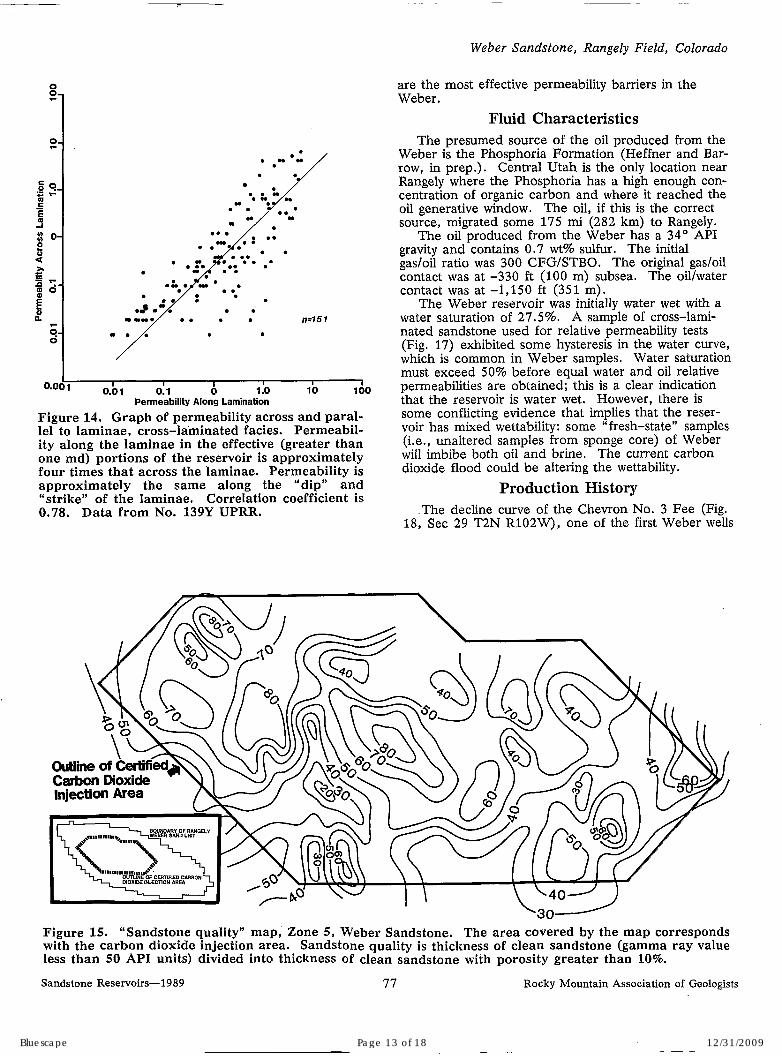
8A). Pore throats for a sample typical of this lithofacies are relatively large (Fig. 8B). There is a large directional component to permeability because of lamination and differential cementation (Fig. 14).
The more thoroughly cemented massive (biotur- bated) facies contains a lower percentage of effective porosity (defined as porosity greater than 10% and permeability greater than one md) compared with cross-laminated sandstones. Porosimeter data from this facies confirm the smaller pore-throat sizes inter- preted from the porosity-permeability cross plot and SEM data (Fig. 9).
The arkosic (fluvial) sandstones and siltstones are rarely effective as reservoirs (Figs. 10 and 13). Com- plete cementation of coarse-grained sandstone is com- mon. What little porosity is seen in thin section (Plate 1) is ineffective. Pressure tests conducted at Rangely also show that the arkosic (fluvial) facies are permeability barriers when not fractured.
The rare carbonates and interdune/extradune mudstones and siltstones were not routinely sampled for PKS (porosity, permeability, and fluid saturation) analyses. However, these facies are always described as tight and barren in cores.
Distribution of Reservoir Facies The subarkosic sandstone with cross-laminated
structure is the reservoir facies of the Weber Sand- stone at Rangely Field. The distribution of this facies is nearly the same as the distribution of the dune depositional environment within each zone. There- fore, the porosity and permeability distribution of the reservoir is correlatable and can be described by depositional facies maps.
A map of sandstone “quality” (Fig. 15), or the percentage of clean (gamma ray less than 50 API units) sandstone with porosity greater than 10% in Zone 5 indicates areas of high and low reservoir qual- ity. A gamma-ray value of 50 API units usually cor- responds to the change from eolian deposits (less than
Sandstone Reservoirs-1989
50 API units) to fluvial deposits (50 API units and greater). There is a distinct northwest trend shown by these data, confirming that the prevailing wind direc- tion could have been from the northeast (Fryberger, 1979). Interestingly, the isopach of the overlying flu- vial zone (Fig. 16) shows an antithetic relationship to sandstone quality ratio. Again, there is a distinct northwest trend to the data. The high sandstone quality areas are interpreted by us as dunes that were anchored and then buried by fluvial sediments. Generally, the concentration of clean subarkosic sand- stone in the Weber decreases to the south and east, and also down-section (Fig. 12). The patterns of reservoir facies distribution become less distinct in these directions and therefore the heterogeneity of the section as a whole is greater. The reason for this change is the dominance of the arkosic Maroon (flu- vial) facies in these directions.
Distribution of Permeability Barriers As in most reservoirs, permeability distribution
controls the ultimate production of hydrocarbons at Rangely Field. Both intergranular and fracture per- meability are present. The contribution of fracture permeability at Rangely is just now being appreciated, not as a benefit, but as a hindrance; fractures appear to act as carbon dioxide “thieves”, decreasing the ef- fectiveness of the current carbon dioxide flood.
The distribution and scale of permeability barriers in the Weber are controlled by depositional environ- ments (Fig. 6). Partial barriers exist at the millimeter scale in the cross-laminated (dune) facies because of differential cementation of the laminae (Fig. 4, Plate 1). If the laminae are contorted, fluid movement will be disrupted. Contorted bedding (Plate 1C) , which can be found in zones several feet thick (Fig. 4), converts what is commonly called “vertical permeabil- ity” into “horizontal permeability,” and vice versa, Even if the laminae are not disturbed, the overall per- meability of the wind-ripple facies is constrained by the low permeability perpendicular to the laminae. Due to rapid lateral changes in bedding attitude, fluid will have to move across the more thoroughly ce- mented, very fine-grained portion of the laminae. However, there is some benefit to this heterogeneity: increased tortuosity increases the effectiveness of the carbon dioxide flood (Warner, 1977). The massively bedded (bioturbated) facies, which can occur in beds up to ten ft (3.0 m) thick, acts as an intermediate- scale permeability barrier. Porosity and permeability data confirm the effectiveness of this facies as a bar- rier (Fig. 13C).
The lateral extent of the arkosic fluvial facies var- ies from hundreds of feet to tens of miles; five of the fluvial zones are used as field-wide markers. A stratigraphic cross section (Fig. 12) gives some indica- tion of the distribution of this facies. Thicknesses can range from zero to tens of feet. The abundance of fluvial beds increases to the southeast across the field and also down-section. The behavior of fluids is quite different in the northwest portion of the field, where the Weber is 10% fluvial, compared with the southeast portion, where the section is 40% fluvial deposits. The fluvial sandstones, siltstones, and shales
Rocky Mountain Association of Geologists 74
Bluescape Page 10 of 18 12/31/2009
E M R L 8 4 X KB: 5319
E M R L U 7 X KB: 5330
E M R L 6 7 X KO: 5319
FEE l O l X KBI 5310
FEE l O O X KB: 5317
FEE 9 9 X KO1 5136
E E? z 0” 0 0 0 0 0 0
k2611 Ft.-/ k2400 F t . 4 2823 F t . 4 k2572 F t . 4 2730 F t.4 2 N g. S 7 CL \o OD \o
2 o
5
Figure 12. North-south stratigraphic cross section over Rangely Field (see Fig. 2 for location). Logs are gamma ray and porosity curves.
less than 10% porosity and gamma ray values over 50 API units decreases to the south and down-section. Effective sandstone (10% or greater porosity) is highlighted by the black bars in the depth tracks. The amount of arkosic, fluvial rocks with
8.
I’ I
Bluescape Page 11 of 18 12/31/2009
Bowkei- and Jackson
c
. . .
md
.. ..-.. ....... *--J -.- -- -. -- .... ..*
....... / sl- , , r BAD ao6 aio ais 0.20
Fmosm
e
. . * . .
.. .. . .
*. . *, :"". . . . . . ..
c d
f I
m o s m
-. . a , .. - .. . . Mean Porosity: . IJ 7 1 . . . . . Meen Permeability: .249 md * . .- . . .. - . . . . . . . . . . . . . . . . . . . . . .. - . . . . . . . . . . . . . - . . . . . .
. ..- .. .-.. . . , c D a06 aio a16 am
B
* . : .*.a
. a: .-. :.. * . *
-, - * * . . . . . . . . . . . 0.. ?. ... . . :***. .. . . . . . . . . . . . . . . . . . . '. f .*,*. . : a . 0 . . . . . . . . . . . .. 4 ........ :
. * . . . . . . ' . .. *. . '>. . . . . .
. * : . Mean Porosity: .09 7 Mean Permeability: 1.216 md
.- . *. . . . . . . . . . ... - . . . . . . . . . . . . . . . . . . .- . . . .... -.-... .
l 0 a06 0.10 0.16
PORosrrY
. . . Mean Porosity: .035 Mean Permeability: .023 md . . - . .
.. . . -. . . . . . . . . . .-. .- . . . . . -.-.-.--. * . --.- . . . . c
am abs a i o a16 POROSITY
Figure 13. Permeability is measured to air, with no Klinkenberg or overburden pressure corrections made; measurements made parallel to laminae, if present. Porosity measured by Boyle's Law (helium) method. Arithmetic mean porosity and geometric mean perme- ability reported. Data from No. 139Y UPRR well. A. Data from all three major lithologic facies (n=641). B. Data from the cross-laminated facies only (n=275). This is the most permeable facies. C. Data from the massive (bioturbated) facies only (n=231). Note trend toward lower permeabilities. D. Data from the arkosic (fluvial) facies. Includes sandstones and siltstones; shales were not analyzed (n=135). This is not reservoir rock.
Permeability and porosity data, Weber Sandstone.
Sandstone Reservoirs-1 9 8 9 76 Rocky Mountain Association of Geologists
Bluescape Page 12 of 18 12/31/2009
Weber Sandstone, Rangely Field, Colorado
i I ’ I
0 il : . .
-0
. *a*: / . *J
..
-.a/ .. . .
. . . .
n=l5 1
I I I I I 1
Figure 14. Graph of permeability across and paral- lel to laminae, cross-lainhated facies. Permeabil- ity along the laminae in the effective (greater than one md) portions of the reservoir is approximately four times that across the laminae. Permeability is approximately the same along the “dip” and “strike” of the laminae. Correlation coefficient is 0.78. Data from No. 139Y UPRR.
O.OO1 0.bl 0.1 0 1 .o 10 100 Permeability Along Lamination
are the most effective permeability barriers in the Weber.
Fluid Characteristics The presumed source of the oil produced from the
Weber is the Phosphoria Formation (Heffner and Bar- row, in prep.). Central Utah is the only location near Rangely where the Phosphoria has a high enough con- centration of organic carbon and where it reached the oil generative window. The oil, if this is the correct source, migrated some 175 mi (282 km) to Rangely.
The oil produced from the Weber has a 34” API gravity and contains 0.7 wt% sulfur. The initial gadoil ratio was 300 CFG/STBO. The original gadoil contact was at -330 f t (100 m) subsea. The oil/water contact was at -1,150 f t (351 m).
The Weber reservoir was initially water wet with a water saturation of 27.5%. A sample of cross-lami- nated sandstone used for relative permeability tests (Fig. 17) exhibited some hysteresis in the water curve, which is common in Weber samples. Water saturation must exceed 50% before equal water and oil relative permeabilities are obtained; this is a clear indication that the reservoir is water wet. However, there is some conflicting evidence that implies that the reser- voir has mixed wettability: some fresh-state” samples (i.e., unaltered samples from sponge core) of Weber will imbibe both oil and brine. The current carbon dioxide flood could be altering the wettability.
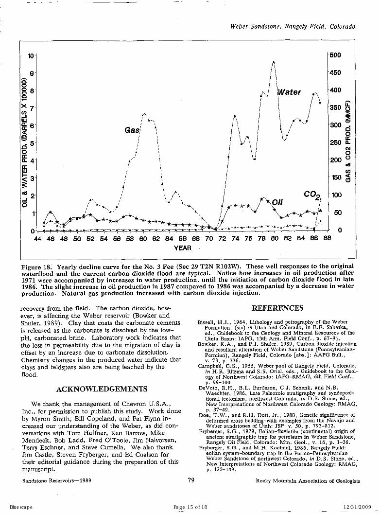
Production History .The decline curve of the Chevron No. 3 Fee (Fig.
18, Sec 29 T2N R102W), one of the first Weber wells
Sandstone Reservoirs-1 9 8 9 77 Rocky Mountain Association of Geologists
Bluescape Page 13 of 18 12/31/2009

Bowker and Jackson
166-
56
4- s $16
iE 5 - E
ti
0
P
h Y
m E P Q > m Q E
1 - - .5
0 .1
completed in the field, is typical of wells drilled near the crest of the anticline in the gas cap. Other wells within the carbon dioxide injection area exhibit a similar response to the tertiary recovery project; i.e., increased oil and natural gas production, and de- creased water production.
-
CONCLUSIONS The three major lithofacies described herein (cross
laminated, massively bedded, and arkosic) are easily recognized in cores of the Weber. These deposits can be discerned on wireline logs and, hence, the various lithofacies can be mapped without the benefit of core, Distribution of the lithofacies is important because the arlcosic fluvial units form extensive permeability barri- ers within the Weber. On a smaller scale, the tightly cemented massive (bioturbated) zones also form effec- tive barriers to fluid flow.
Cross lamination, enhanced by differential cemen- tation of the laminae, forms the smallest scale of res- ervoir heterogeneity. Permeability measurements of the cross-laminated facies vary depending on the ori- entation of the sample plug relative to the cross lami- nation. Fractures add to heterogeneity.
The Weber experienced a complex diagenesis,
-
d@+
p I
w - / / \ \
I 1 -
I t I I I which included, late in diagenesis, precipitation of , I
20 46 66 80 166 asphaltene. Asphaltene is found in other portions of
Bluescape Page 14 of 18 12/31/2009
I
I
I
Weber Sandstone, Rangely Field, Colorado
I \
44 46 48 50 52 54 56 58 60 62 64 66 68 70 72 74 76 78 80 82 84 86 88 YEAR
I I
Figure 18; Yearly decline curve for the No. 3 Fee (Sec 29 T2N R102W). These well responses to the original waterflood and the current carbon dioxide flood are typical. Notice how increases in oil production after 1971 were accompanied by increases in water production, until the initiation of carbon dioxide flood in late 1986. The slight increase in oil production in 1987 compared to 1986 was accompanied by a decrease in water production. Natural gas production increased with carbon dioxide injection.
recovery from the field. The carbon dioxide, how- ever, is affecting the Weber reservoir (Bowker and Shuler, 1989). Clay that coats the carbonate cements is released as the carbonate is dissolved by the low- pH, carbonated brine. Laboratory work indicates that the loss in permeability due to the migration of clay is offset by an increase due to carbonate dissolution. Chemistry changes in the produced water indicate that clays and feldspars also are being leached by the flood.
ACKNOWLEDGEMENTS
We thank the management of Chevron U.S.A., Inc., for permission to publish this study. Work done by Myron Smith, Bill Copeland, and Pat Flynn in- creased our understanding of the Weber, as did con- versations with Tom Heffner, Ken Barrow, Mike Mendeck, Bob Ladd, Fred O’Toole, Jim Halvorsen, Terry Eschner, and Steve Cumella, We also thank Jim Castle, Steven Fryberger, and Ed Coalson for their editorial guidance during the preparation of this manuscript.
WFERENCES
Bissell, H.J., 1964, Lithology and petrography of the Weber Formation, (sic) in Utah and Colorado, in E.F. Sabatka, ed., Guidebook to the Geology and Mineral Resources of the Uinta Basin: IAPG, 13th Ann. Field Conf., p. 67-91.
Bowker, K.A., and P.J. Shuler, 1989, Carbon dioxide injection and resultant alteration of Weber Sandstone (Pennsylvanian- Permian), Rangely Field, Colorado [abs.]: AAPG Bull., v. 73, p. 336.
Campbell, G.S., 1955, Weber pool of Rangely Field, Colorado, in H.R. Ritzma and S . S . Oriel, eds., Guidebook to the Geol- ogy of Northwest Colorado: IAPG-RMAG, 6th Field Conf.,
Waechter, 1986, Late Paleozoic stratigraphy and syndeposi- tional tectonism, northwest Colorado, in D.S. Stone, ed., New Interpretations of Northwest Colorado Geology: RMAG,
Doe, T.W., and R.H. Dott, Jr., 1980, Genetic significance of deformed cross bedding-with examples from the Navajo and Weber sandstones of Utah: JSP, v. 50, p. 793-812.
Fryberger, S.G., 1979, Eolian-fluviatile (continental) origin of ancient stratigraphic trap for petroleum in Weber Sandstone, Rangely Oil Field, Colorado: Mtn. Geol., v. 16, p. 1-36.
Fryberger, S.G., and M.H. Koelmel, 1986, Rangely Field: eolian system-boundary trap in the Permo-Pennsylvanian Weber Sandstone of northwest Colorado, in D.S. Stone, ed., New Interpretations of Northwest Colorado Geology: RMAG,
p. 99-100 DeVoto, R.H., B.L. Burtleson, C.J. Schenk, and N.B.
p. 37-49.
p. 123-149.
Sandstone Reservoirs-1989 79 Rocky Mountain Association of Geologists
Bluescape Page 15 of 18 12/31/2009

60
50
40
30
20
10
0
No. of Fields I 60 I ....................... ........................................................................
...............................................................................................................
Bowker and Jackson
Gale, H.S., 1908, Geology of the Rangely oil district, Rio Mayer, L., L.D. McFadden, and J.W. Harden, Distribution of calcium carbonate in desert soils-a model: Geology, v. 16,
Raleigh, C.B., J.H. Healy, and J.P. Bredenoeft, 1976, An experiment in earthquake control at Rangely, Colorado: Sci- ence, v . , 191, p. 1230-1236.
Warner, H.R., 1977, An evaluation of miscible C02 flooding in waterflooded sandstone reservoirs: JPT, v. 29, p. 1339-1347.
Blaaco County, Colorado: USGS Bull. 350, 61 p.
AAPG special publication.
Am. Jour. Sci., 3 Ser., v. 11, .p. 475-482.
stratigraphic, and diagenetic history of the Weber Sandstone in the Rangely Field area, Colorado, in J.A. Peterson, ed., Paleotectonics and Sedimentation in the Rocky Mountain Region: AAPG Mem. 41, p. 371-396.
Heffner, T.A., and K.T. Barrow, in prep., Rangely Field: p. 303-306.
King, C., 1876, Paleozoic subdivisions on the 40th parallel:
Koelmel, M.H., 1986, Post-Mississippian paleotectonic,
Rocky Mountain Association of Geologists
....................... .................................. ................... ..............
.......................................................................................................... I
.......................
18
................................ .........................................
//mm ............................................................................................... A 5 5
I I
Wyoming Colorado Montana Utah Nebraska No. Dakota
I = Structural Stratigraphic Combination c When considering the largest (>10,000,000 BOE) fields in the Rocky Mountains with sandstone reservoirs (n=155), Wyoming accounts for 72% of all fields and 78% of the structural fields. Numer- ous large gas fields in the San Juan Basin are not included in the dataset. Production data compli- ments of Petroleum Information. Compiled by John W. Robinson, 1989. See page 351ff for further information.
Sandstone Reservoirs-1989 80
Bluescape Page 16 of 18 12/31/2009

The Weber Sandstone at Rangely Field, Colorado Kent A . Bowker, William D. Jackson
PLATE 1. Thin-section photomicrographs of the major Weber facies. Samples are from the No. 139Y UPRR. Thin sections came from the same respective depths as samples in Figure 4. All photomicrographs taken with plane light. Bars a t lower right corner of each photomicrograph represent 200 microns. Each sample was im- pregnated with blue epoxy, and stained with Alizarin R e d 4 and potassium fer- ricyanide.
A. Wind-ripple lamina. Grain size coarsens upward within the lamina. The very fine-grained (lower porosity) portion of the overlying lamina can be seen a t the top of the photomicrograph. 5,657.7 ft (1,724.5 m).
B. Massive bioturbated sandstone. Calcite crystals in the center of the photomicro- graph have iron-rich outer rims. Dolomite and ferroan dolomite also are present. 5,963.1 ft (1,817.6 m).
C. Wind-ripple lamina. Dolomite cements the lower, very fine-grained portion of the lamina. Asphaltene (opaque material) lines some of the pores. 5,657.7 ft (1,724.4 m).
D. Massive bioturbated sandstone. Note low porosity (approximately 5%) , abundant carbonate cement, and clay coatings. 5,963.1 f t (1,817.6 m).
E. Upper portion of a wind-ripple lamina. Ferroan dolomite (stained dark blue) fills three pores in the center of the photomicrograph. Asphaltene lines a few of the pores. 5,657.7 ft (1,724.4 m).
F. Arkosic fluvial sandstone. Note poor sorting and angular grains. Porosity is not effective (see text and Fig. 10). 6,160.7 f t (1,877.8 m).
G. Massive bioturbated sandstone. Notice decrease in porosity compared to cross- laminated sandstones. Porosity is occluded with calcite, ferroan calcite, dolomite, and ferroan dolomite; quartz overgrowths also are present. Clay lines some of the pores. 5,963.1 ft (1,817.6 m).
H. Arkosic fluvial sandstone. Note poor porosity and poor connectivity of pores. 6,160.7 ft (1,877.8 m).
Sandstone Reservoirs-1 9 8 9 310
Bluescape Page 17 of 18 12/31/2009

i
Sandstone Resewdrs- 1989 311 Rocky Mountain Association of Geologists
Bluescape Page 18 of 18 12/31/2009