Embed Size (px)
Citation preview
THE WORLD’S LEADING
MICRO MECHANICAL TESTER
Prepared byPIERRE LEROUX & DUANJIE LI, PhD
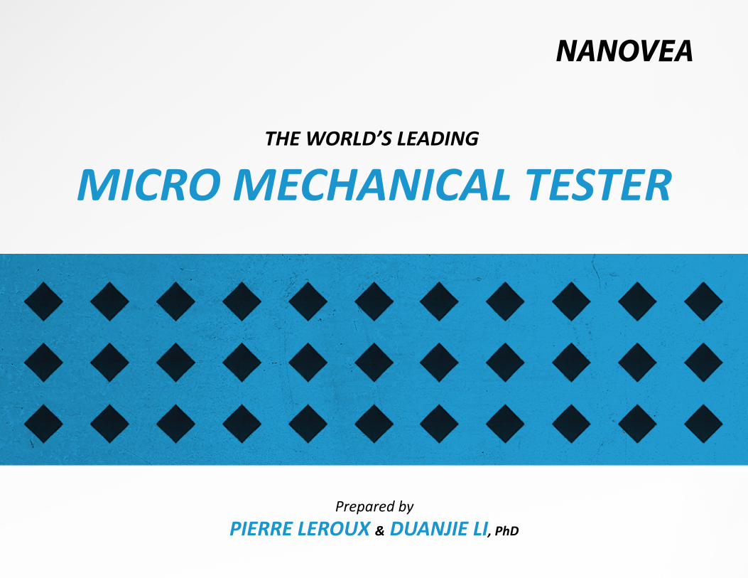
INTRODUCTIONStandard Vickers Micro Hardness Testers have usable load ranges from 10 to 2000 gram force (gf). Standard Vickers Macro Hardness Testers load from 1 to 50 Kgf. These instruments are not only very limited in range of loads but they are also inaccurate when dealing with rougher surfaces or low loads when indents become too small to be measured visually. These limita�ons are intrin-sic to older technology and as a result, instrumented indenta�on is becoming the standard choice due to the higher accuracy and performance it brings.
With NANOVEA's world leading micro mechanical tes�ng systems, Vickers hardness is automa�cally calculated from depth versus load data with the widest load range on a single module ever available (0.3 grams to 2 Kg or 6 grams to 40 Kg). Because it measures hardness from depth versus load curves, the NANOVEA Micro Module can measure any type of materials including very elas�c ones. It also can provide not only Vickers hardness but also accurate elas�c modulus and creep data in addi�on to other types of test such as scratch adhesion tes�ng, wear, fa�gue tes�ng, yield strength and fracture toughness for a complete range of quality control data.
NOW THE WORLD'S LEADING MICRO MECHANICAL TESTING
In this applica�ons note, it will be explained how the Micro Module has been designed to offer the world's leading instrumented indenta�on and scratch tes�ng. The Micro Module’s wide range tes�ng capability is ideal for many applica�ons. For example, the load range allows for accurate hardness and elas�c modulus measurements of thin hard coa�ngs and can then apply much higher loads to measure the adhesion of these same coa�ngs.
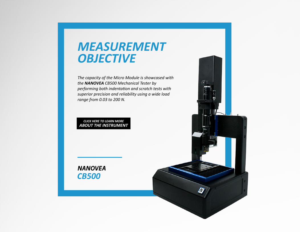
MEASUREMENT OBJECTIVEThe capacity of the Micro Module is showcased with the NANOVEA CB500 Mechanical Tester by performing both indentation and scratch tests with superior precision and reliability using a wide load range from 0.03 to 200 N.
CB500
CLICK HERE TO LEARN MOREABOUT THE INSTRUMENT
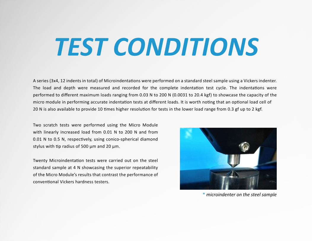
A series (3x4, 12 indents in total) of Microindenta�ons were performed on a standard steel sample using a Vickers indenter. The load and depth were measured and recorded for the complete indenta�on test cycle. The indenta�ons were performed to different maximum loads ranging from 0.03 N to 200 N (0.0031 to 20.4 kgf) to showcase the capacity of the micro module in performing accurate indenta�on tests at different loads. It is worth no�ng that an op�onal load cell of 20 N is also available to provide 10 �mes higher resolu�on for tests in the lower load range from 0.3 gf up to 2 kgf.
Two scratch tests were performed using the Micro Module with linearly increased load from 0.01 N to 200 N and from 0.01 N to 0.5 N, respec�vely, using conico-spherical diamond stylus with �p radius of 500 μm and 20 μm.
Twenty Microindenta�on tests were carried out on the steel standard sample at 4 N showcasing the superior repeatability of the Micro Module’s results that contrast the performance of conven�onal Vickers hardness testers.
TEST CONDITIONS
* microindenter on the steel sample
INDENTER TYPE
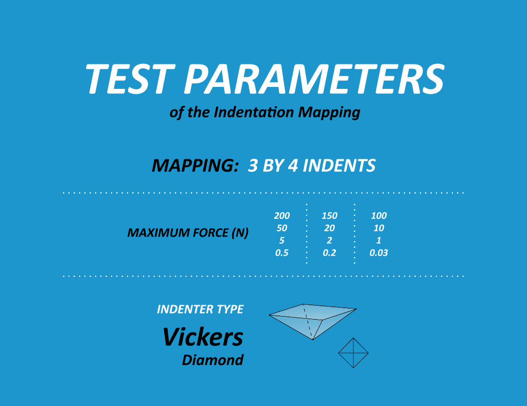
VickersDiamond
TEST PARAMETERSof the Indentation Mapping
MAPPING: 3 BY 4 INDENTS
MAXIMUM FORCE (N)100101
0.03
150202
0.2
200505
0.5
RESULTS & DISCUSSIONThe new Micro Module has a unique combina�on of Z-motor, high-force load cell and a high precision capaci�ve depth sensor. The unique u�liza�on of independent depth and load sensors ensures high accuracy under all condi�ons.
Conven�onal Vickers hardness tests use diamond square-based pyramid indenter �ps that create square shaped indents. By measuring the average length of the diagonal, d, the Vickers hardness can be calculated.
In comparison, the instrumented indenta�on technique used by NANOVEA's Micro Module directly measures the mechanical proper�es from indenta�on load & displacement measurements. No visual observa�on of the indent is required. This eliminates user or computer image processing errors in determining the d values of the indenta�on. The high accuracy capacitor depth sensor with a very low noise level of 0.3 nm can accurately measure the depth of indents that are difficult or impossible to be measured visually under a microscope with tradi�onal Vickers hardness testers.
In addi�on, the can�lever technique used by compe�tors applies the normal load on a can�lever beam by a spring, and this load is in turn applied on the indenter. Such a design has a flaw in case a high load is applied - the can�lever beam cannot provide sufficient structural s�ffness, leading to deforma�on of the can�lever beam and in turn misalignment of the indenter. In comparison, the Micro Module applies the normal load via the Z-motor ac�ng on the load cell and then the indenter for direct load applica�on. All the elements are ver�cally aligned for maximum s�ffness, ensuring repeatable and accurate indenta�on and scratch measurements in the full load range.
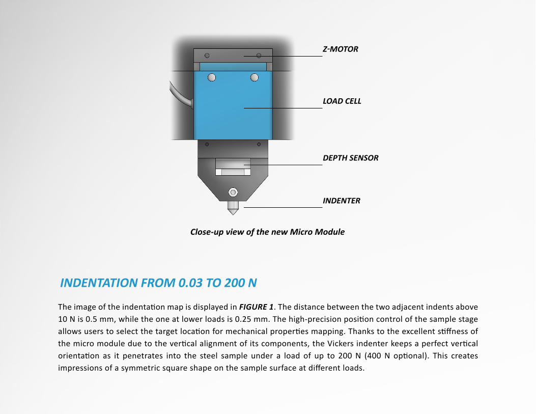
The image of the indenta�on map is displayed in FIGURE 1. The distance between the two adjacent indents above 10 N is 0.5 mm, while the one at lower loads is 0.25 mm. The high-precision posi�on control of the sample stage allows users to select the target loca�on for mechanical proper�es mapping. Thanks to the excellent s�ffness of the micro module due to the ver�cal alignment of its components, the Vickers indenter keeps a perfect ver�cal orienta�on as it penetrates into the steel sample under a load of up to 200 N (400 N op�onal). This creates impressions of a symmetric square shape on the sample surface at different loads.
INDENTATION FROM 0.03 TO 200 N
INDENTER
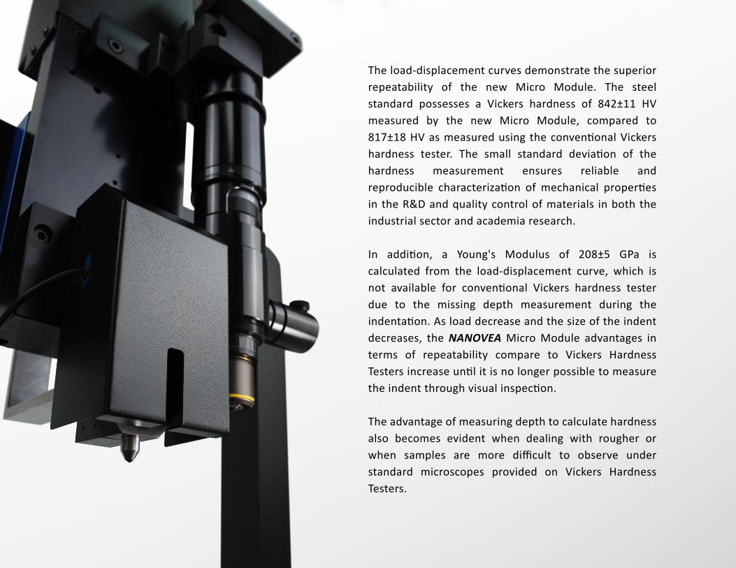
Close-up view of the new Micro Module
DEPTH SENSOR
LOAD CELL
Z-MOTOR
In contrast, the loading system of a can�lever beam structure used by compe�tors may suffer from undesired bending and unstableness of the stylus during the scratch tests under high loads, which results in zigzags taking place in the scratch tracks. Such a behavior introduces errors in scratch track width measurement and determina�on of cri�cal loads for further analysis of the scratch track.
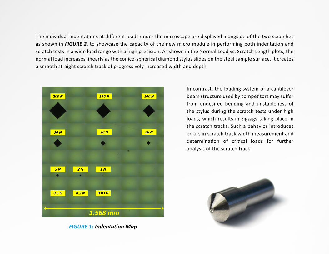
The individual indenta�ons at different loads under the microscope are displayed alongside of the two scratches as shown in FIGURE 2, to showcase the capacity of the new micro module in performing both indenta�on and scratch tests in a wide load range with a high precision. As shown in the Normal Load vs. Scratch Length plots, the normal load increases linearly as the conico-spherical diamond stylus slides on the steel sample surface. It creates a smooth straight scratch track of progressively increased width and depth.
FIGURE 1: Indentation Map
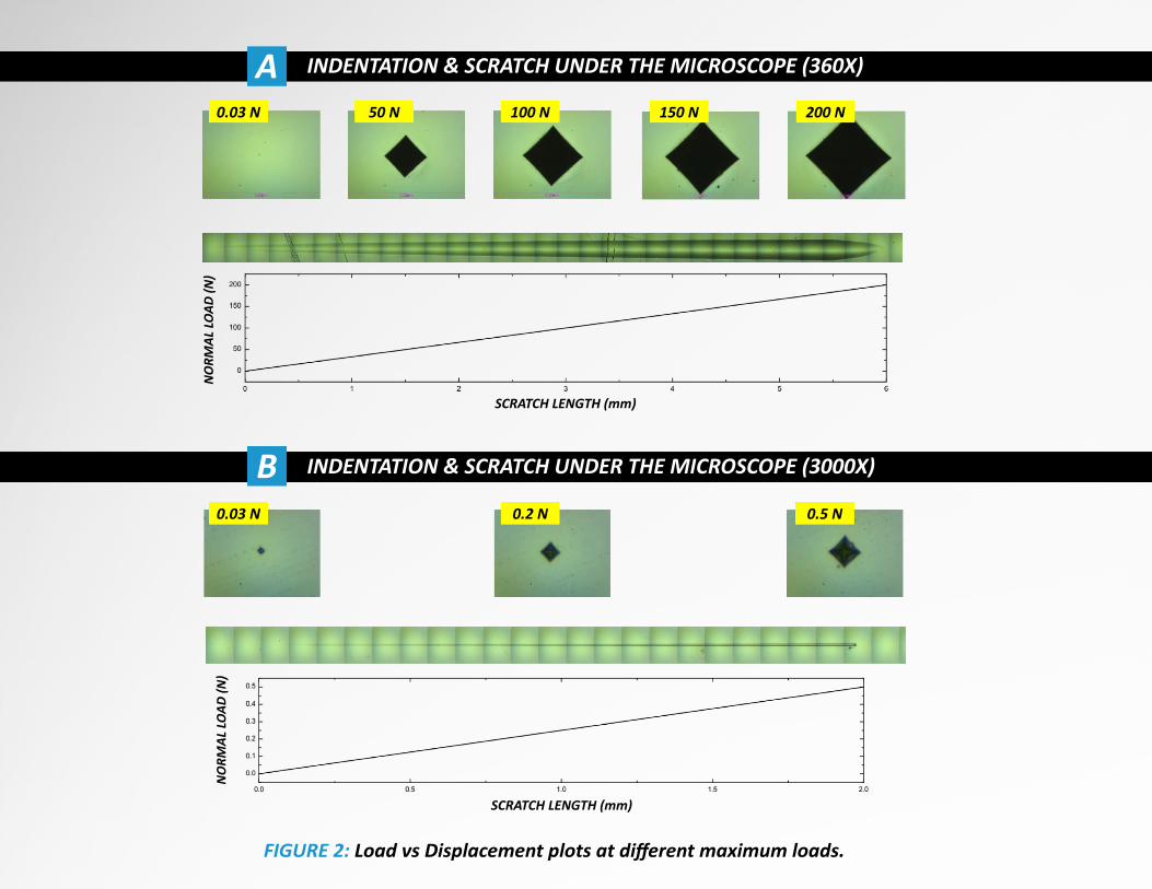
FIGURE 2: Load vs Displacement plots at different maximum loads.
SCRATCH LENGTH (mm)
SCRATCH LENGTH (mm)
INDENTATION & SCRATCH UNDER THE MICROSCOPE (360X)
INDENTATION & SCRATCH UNDER THE MICROSCOPE (3000X)B
A0.03 N 50 N 100 N 150 N 200 N
0.03 N 0.2 N 0.5 N
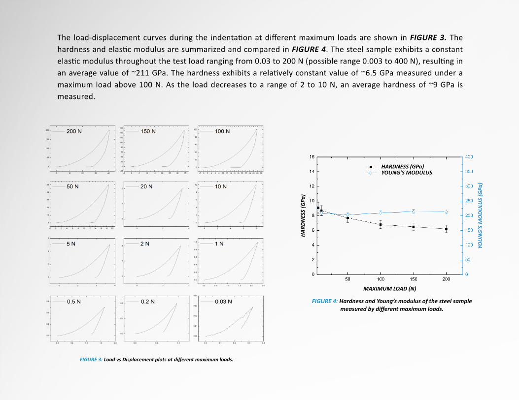
FIGURE 3: Load vs Displacement plots at different maximum loads.
FIGURE 4: Hardness and Young’s modulus of the steel sample measured by different maximum loads.
HARDNESS (GPa)YOUNG’S MODULUS
MAXIMUM LOAD (N)
The load-displacement curves during the indenta�on at different maximum loads are shown in FIGURE 3. The hardness and elas�c modulus are summarized and compared in FIGURE 4. The steel sample exhibits a constant elas�c modulus throughout the test load ranging from 0.03 to 200 N (possible range 0.003 to 400 N), resul�ng in an average value of ~211 GPa. The hardness exhibits a rela�vely constant value of ~6.5 GPa measured under a maximum load above 100 N. As the load decreases to a range of 2 to 10 N, an average hardness of ~9 GPa is measured.
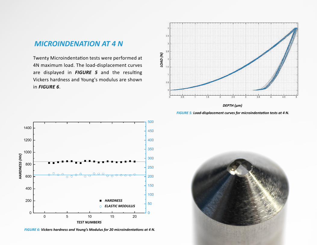
Twenty Microindenta�on tests were performed at 4N maximum load. The load-displacement curves are displayed in FIGURE 5 and the resul�ng Vickers hardness and Young's modulus are shown in FIGURE 6.
MICROINDENATION AT 4 N
FIGURE 6: Vickers hardness and Young’s Modulus for 20 microindentations at 4 N.
TEST NUMBERS
HARDNESSELASTIC MODULUS
FIGURE 5: Load-displacement curves for microindentation tests at 4 N.
DEPTH (μm)
The load-displacement curves demonstrate the superior repeatability of the new Micro Module. The steel standard possesses a Vickers hardness of 842±11 HV measured by the new Micro Module, compared to 817±18 HV as measured using the conven�onal Vickers hardness tester. The small standard devia�on of the hardness measurement ensures reliable and reproducible characteriza�on of mechanical proper�es in the R&D and quality control of materials in both the industrial sector and academia research.
In addi�on, a Young's Modulus of 208±5 GPa is calculated from the load-displacement curve, which is not available for conven�onal Vickers hardness tester due to the missing depth measurement during the indenta�on. As load decrease and the size of the indent decreases, the NANOVEA Micro Module advantages in terms of repeatability compare to Vickers Hardness Testers increase un�l it is no longer possible to measure the indent through visual inspec�on.
The advantage of measuring depth to calculate hardness also becomes evident when dealing with rougher or when samples are more difficult to observe under standard microscopes provided on Vickers Hardness Testers.
In this study, we have shown how the new world leading NANOVEA Micro Module (200 N range) performs unmatched reproducible and precise indenta�on and scratch measurements under a wide load range from 0.03 to 200 N (3 gf to 20.4 kgf). An op�onal lower range Micro Module can provide tes�ng from 0.003 to 20 N (0.3 gf to 2 kgf). The unique ver�cal alignment of the Z-motor, high-force load cell and depth sensor ensures maximum structural s�ffness during measurements. The indenta�ons measured at different loads all possess a symmetric square shape on the sample surface. A straight scratch track of progressively increased width and depth is created in the scratch test of a 200 N maximum load.
The new Micro Module can be configured on the PB1000 (150 x 200 mm) or the CB500 (100 x 50 mm) mechanical base with a z motoriza�on (50 mm range). Combined with a powerful camera system (posi�on accuracy of 0.2 microns) the systems provide the best automa�on and mapping capabili�es on the market. NANOVEA also offers a unique patented func�on (EP No. 30761530) which allows verifica�on and calibra�on of Vickers indenters by performing a single indent across the full range of loads. In contrast, standard Vickers Hardness Testers can only provide calibra�on at one load.
Addi�onally, the NANOVEA so�ware enables a user to measure the Vickers hardness via the tradi�onal method of measuring the indent diagonals if needed (for ASTM E92 & E384). As shown, in this document, depth versus load hardness tes�ng (ASTM E2546 and ISO 14577) performed by a NANOVEA Micro Module is precise and reproducible compared to Tradi�onal Hardness Testers. Especially for samples that cannot be observed/measured with a microscope.
In conclusion, the higher accuracy and repeatability of the Micro Module design with its broad range of loads and tests, high automa�on and mapping op�ons renders the tradi�onal Vickers hardness testers obsolete. But likewise with scratch and micro scratch testers s�ll currently offered but designed with flaws in the 1980's.
The con�nuous development and improvement of this technology makes NANOVEA a world leader in micro mechanical tes�ng.
CONCLUSION