Embed Size (px)
Citation preview
The Xerox DocuPrint 4517/4517mp Network Laser Printers
User Guide
titlpage.frm Page 1 Friday, July 11, 1997 8:10 PM
Xerox Corporation Xerox Canada, Limited701 South Aviation Blvd. 5650 Yonge StreetEl Segundo, CA North York, Ontario90245 CanadaUSA M2M 4G7
Americas Customer Operations Rank Xerox, Limited800 Long Ridge Road ParkwayStamford, CT Marlow06904-1600 BuckinghamshireUSA SL7 1YL
United Kingdom
Copyright © 1996, 1997 Xerox Corporation. All Rights Reserved.
Copyright protection claimed includes all forms of matters of copyrightable materials and information now allowed by statutory or judicial law or hereinafter granted, including without limitation, material generated from the software programs which are displayed on the screen such as styles, templates, icons, screen displays, looks, etc.
XEROX®, The Document Company®, the stylized X, DocuPrint, and 4517 are trademarks of Xerox Corporation or its subsidiaries.
Adobe® and PostScript® are trademarks of Adobe Systems Incorporated.
TrueRes is a trademark of DP-Tek. PCL, HP, and LaserJet are trademarks of Hewlett-Packard Company. IBM is a trademark of International Business Machines Corporation. Microsoft, Microsoft Windows, Microsoft Word, MS, and MS-DOS are trademarks of Microsoft Corporation. Univers is a trademark of Linotype AG or its subsidiaries. WordPerfect is a trademark of WordPerfect Corporation. Centronics is a trademark of Centronics Corporation. Macintosh and TrueType are trademarks of Apple Computer, Incorporated. OnPage is a trademark of COMPUTER:applications, Inc. All other product names are trademarks/tradenames of their respective owners.
PCL and PCL 5e are trademarks of Hewlett Packard Company. This printer contains an emulation of the Hewlett Packard PCL 5e command language, recognizes HP PCL 5e commands, and processes these commands in a manner comparable with Hewlett Packard LaserJet printer products.
NoticeSpecifications described in this publication are subject to change without notice. Use of some features may be limited by your hardware or software configuration. Contact your dealer, Xerox, or Rank Xerox for details.
titlpage.frm Page 2 Friday, July 11, 1997 8:10 PM
Table of Contentsi
D o c u P r i n t 4 5 1 7 U s e r G u i d e ❖ i
Chapter 1 DocuPrint 4517 Quick Tour ................................................. 1-1
DocuPrint 4517 and DocuPrint 4517mp Models ................. 1-3
How Much of This Book Must I Read? ................................. 1-4
Printer Components .............................................................. 1-5
Special Features .................................................................... 1-6
Power Saver ....................................................................... 1-6
High Resolution Printing ................................................... 1-6
Edge to Edge Printing ....................................................... 1-7
Automatic Tray Switching ................................................. 1-7
Automatic Language Sensing and Switching .................. 1-7
State Saving ....................................................................... 1-8
Printer Generated Reports ................................................ 1-8
PostScript Upgrades ........................................................... 1-8
Duplex Printing .................................................................. 1-9
Increased Paper Handling ................................................. 1-9
Collating and Offsetting ................................................... 1-9
Memory Expansion .......................................................... 1-10
Memory Considerations ..................................................... 1-11
contents.frm Page i Friday, July 11, 1997 8:11 PM
T a b l e o f C o n t e n t s
ii ❖ D o c u P r i n t 4 5 1 7 U s e r G u i d e
Maintaining the Printer ...................................................... 1-13
Cleaning the Printer ........................................................ 1-13
Replacing the EP Cartridge ............................................. 1-13
Recycling the EP Cartridge .............................................. 1-13
Replacing the Fuser Cartridge/Bias Transfer Roll ........... 1-14
Technical Support ............................................................... 1-15
Before Calling for Service ................................................ 1-15
Transporting the Printer ..................................................... 1-16
Chapter 2 Paper Handling ...................................................................... 2-1
Selecting Paper ..................................................................... 2-3
Storing Paper ..................................................................... 2-4
Using the Main Tray or Lower Tray ..................................... 2-5
Adjusting the Main Tray for Paper Size ........................... 2-7
Adjusting the Lower Tray for Paper Size ......................... 2-8
Using the Front Tray ............................................................. 2-9
Loading the Front Tray .................................................... 2-11
Automatic Tray Switching .................................................. 2-13
PostScript Tray Switching ................................................ 2-13
PCL Tray Switching (Source Mapping) ............................ 2-14
Using the Mailbox/Collator ................................................ 2-19
Printing to the Mailbox/Collator .................................... 2-20
Password Protecting Jobs ................................................ 2-20
Opening Bins .................................................................... 2-25
Using the Offset Catch Tray (OCT) ..................................... 2-26
Using the Envelope Feeder ................................................ 2-27
Loading the Envelope Feeder ......................................... 2-28
Duplex (Two-Sided) Printing .............................................. 2-29
Print Orientation and Control Panel Settings ................ 2-30
contents.frm Page ii Friday, July 11, 1997 8:11 PM
T a b l e o f C o n t e n t s
D o c u P r i n t 4 5 1 7 U s e r G u i d e ❖ iii
Chapter 3 Using the Control Panel ...................................................... 3-1
Control Panel Features ......................................................... 3-2
The Display ......................................................................... 3-2
The Keys ............................................................................. 3-3
Navigating the Menu System ............................................... 3-6
Menu Indicators ................................................................. 3-8
Setting a Menu Option ..................................................... 3-9
Main Menu .......................................................................... 3-11
Language Menu .................................................................. 3-12
Mailbox Menu ..................................................................... 3-13
PCL Emulat Menu ................................................................ 3-14
PostScript Menu .................................................................. 3-17
Interface Menu ................................................................... 3-20
LocalTalk Menu Options ................................................. 3-23
Ethernet Menu Options .................................................. 3-23
Token Ring Menu Options .............................................. 3-24
System Menu ....................................................................... 3-25
Test Menu ............................................................................ 3-26
Reset Menu ......................................................................... 3-27
Chapter 4 DocuPrint 4517 Printer Drivers .......................................... 4-1
DocuPrint 4517 PCL 5e Emulation Printer Drivers .............. 4-2
DocuPrint 4517 PostScript Printer Drivers ........................... 4-3
Chapter 5 Using the Hard Drive / Downloading Fonts .................... 5-1
Hard Drive Considerations ................................................... 5-2
Print/Disk Spooling ............................................................ 5-2
State Saving ....................................................................... 5-2
Formatting the Hard Drive ................................................ 5-3
Downloading Fonts and Macros .......................................... 5-4
contents.frm Page iii Friday, July 11, 1997 8:11 PM
T a b l e o f C o n t e n t s
iv ❖ D o c u P r i n t 4 5 1 7 U s e r G u i d e
Chapter 6 Troubleshooting .................................................................... 6-1
Printer Operation Problems ................................................. 6-2
Control Panel Messages ........................................................ 6-6
Paper Jams ........................................................................... 6-28
What Causes a Paper Jam? .............................................. 6-28
Clearing Paper Jams ........................................................ 6-28
Print Quality Problems ........................................................ 6-35
Appendix A Ordering Printer Options ................................................... A-1
Appendix B Replacing Consumables ....................................................... B-1
Replacing the EP Cartridge .................................................. B-2
Replacing the Fuser Cartridge/BTR ...................................... B-5
Appendix C Installing and Removing Printer Options ........................ C-1
Precautions ............................................................................ C-3
Memory SIMMs ..................................................................... C-4
Installing a Memory SIMM ................................................ C-5
Removing a Memory SIMM ............................................... C-8
PostScript SIMM .................................................................. C-10
Installing a PostScript SIMM ............................................ C-10
Removing a PostScript SIMM .......................................... C-13
Hard Drive ........................................................................... C-16
Installing the Hard Drive ................................................. C-16
Removing the Hard Drive ................................................ C-19
Duplex Module ................................................................... C-21
Installing the Duplex Module ......................................... C-21
Removing the Duplex Module ........................................ C-23
500-sheet Paper Deck and Cassette ................................... C-24
Installing One 500-sheet Paper Deck and Cassette ....... C-24
Installing Two 500-sheet Paper Decks and Cassettes .... C-27
Removing a 500-sheet Paper Deck and Cassette ........... C-31
contents.frm Page iv Friday, July 11, 1997 8:11 PM
T a b l e o f C o n t e n t s
D o c u P r i n t 4 5 1 7 U s e r G u i d e ❖ v
Offset Catch Tray (OCT) ...................................................... C-33
Installing the OCT ............................................................ C-33
Removing the OCT ........................................................... C-36
Mailbox/Collator ................................................................. C-38
Installing the Mailbox/Collator ....................................... C-38
Removing the Mailbox/Collator ...................................... C-41
Envelope Feeder ................................................................. C-43
Installing the Envelope Feeder ....................................... C-43
Removing the Envelope Feeder ...................................... C-46
Font Cards and Macro Cards .............................................. C-48
Xerox Network Interface Card (XNIC) ............................... C-49
Installing the XNIC ........................................................... C-50
Removing the XNIC ......................................................... C-54
Appendix D Control Panel Options ......................................................... D-1
Appendix E Printer Resident Fonts ......................................................... E-1
Base Printer Fonts ................................................................. E-2
Printing a PCL Font List ..................................................... E-3
PostScript Fonts ..................................................................... E-4
Appendix F Printer Specifications ........................................................... F-1
Appendix G DocuPrint 4517 Unique Printer Commands .................... G-1
Overview ............................................................................... G-2
Paper Size .............................................................................. G-3
Output Trays ......................................................................... G-5
Raster Resolution .................................................................. G-6
Appendix H Environmental Specifications ........................................... H-1
Index ................................................................................................. IX-1
contents.frm Page v Friday, July 11, 1997 8:11 PM

vi ❖ D o c u P r i n t 4 5 1 7 U s e r G u i d e
contents.frm Page vi Friday, July 11, 1997 8:11 PM
Chapter 1
C h a p t e r 1 : D o c u P r i n t 4 5 1 7 Q u i c k T o u r ❖ 1-1
DocuPrint 4517 Quick Tour Chapter1
DocuPrint 4517 and DocuPrint 4517mp Models ................. 1-3
How Much of This Book Must I Read? ................................ 1-4
Printer Components ............................................................. 1-5
Special Features .................................................................... 1-6
Power Saver ......................................................................... 1-6
High Resolution Printing ....................................................... 1-6
Edge to Edge Printing ........................................................... 1-7
Automatic Tray Switching ..................................................... 1-7
Automatic Language Sensing and Switching ........................ 1-7
State Saving ......................................................................... 1-8
Printer Generated Reports .................................................... 1-8
PostScript Upgrades ............................................................. 1-9
Duplex Printing ..................................................................... 1-9
Increased Paper Handling ..................................................... 1-9
Collating and Offsetting ....................................................... 1-9
Memory Expansion ............................................................. 1-10
chapter1.frm Page 1 Friday, July 11, 1997 8:12 PM
D o c u P r i n t 4 5 1 7 Q u i c k T o u r
1-2 ❖ D o c u P r i n t 4 5 1 7 / 4 5 1 7 m p U s e r G u i d e
Memory Considerations ..................................................... 1-11
Maintaining the Printer ...................................................... 1-13
Cleaning the Printer ............................................................ 1-13
Replacing the EP Cartridge ................................................. 1-13
Recycling the EP Cartridge .................................................. 1-14
Replacing the Fuser Cartridge/Bias Transfer Roll .................. 1-14
Technical Support ............................................................... 1-15
Before Calling for Service .................................................... 1-15
Transporting the Printer .................................................... 1-16
chapter1.frm Page 2 Friday, July 11, 1997 8:12 PM
D o c u P r i n t 4 5 1 7 Q u i c k T o u r
C h a p t e r 1 : D o c u P r i n t 4 5 1 7 Q u i c k T o u r ❖ 1-3
DocuPrint4517 and
DocuPrint4517mpModels
This book is for use with both the Xerox DocuPrint 4517 and
DocuPrint 4517mp Network Laser Printers. The DocuPrint 4517mp contains all the components of the DocuPrint 4517, plus the following options:
• Adobe PostScript Level 2
• 4 MB additional memory
• XNIC-E’NET (Xerox Network Interface Card for Ethernet)
As this guide serves both printers, the DocuPrint 4517mp will
hereafter be referred to as the DocuPrint 4517.
Note
Some of the features described in this book apply only to
Version 2.0 or later of the DocuPrint 4517. Version 2.0 is defined as having system controller software version 2.00.xx or later and XNIC version 6.1 or later (if installed). Features
that pertain only to Version 2.0 or later are designated “for V2.0 or later.”
Version 2.0 supports all of the features of the earlier versions and contains the following enhancements:
• Ability to set IP Address (and Subnet Mask and Gateway Address) via the Control Panel.
• Support for LAA (Locally Administered Address) in the
XNIC-T’RING (and setup via the Control Panel).
• Ability to designate the front tray as the first selected input
device for tray switching and source mapping.
• Support for the RFC1759 Standard Printer MIB, plus Xerox
MIB enhancements, for the DocuPrint 4517 via SNMP (enables CentreWare DP and other SNMP tools to remotely manage the DocuPrint 4517).
• An increase of base memory to 4 MB for the DocuPrint 4517 and 8 MB for the DocuPrint 4517mp.
• Support for the optional serial port. The serial port is not a
customer installable option, and must be ordered as a unique printer configuration at the time of the initial printer order.
chapter1.frm Page 3 Friday, July 11, 1997 8:12 PM
D o c u P r i n t 4 5 1 7 Q u i c k T o u r
1-4 ❖ D o c u P r i n t 4 5 1 7 / 4 5 1 7 m p U s e r G u i d e
How Much ofThis Book
Must I Read?
You do not have to read any of this guide to use your
DocuPrint 4517. The DocuPrint 4517 is ready to go after you set it up following the instructions in the Setting Up Guide.
Use this guide as a reference for:
• Learning about special printer features [“Special
Features” (page 1-6)]
• Tips on taking care of the printer [“Maintaining the Printer” (page 1-13)]
• Paper specifications, loading paper, and duplex printing (Chapter 2: Paper Handling)
• Instructions on using the Control Panel (Chapter 3: Using the Control Panel and Appendix D: Control Panel
Options)
• Installing printer drivers (Chapter 4: DocuPrint 4517 Printer Drivers)
• Downloading fonts (Chapter 5: Using the Hard Drive /
Downloading Fonts)
• Troubleshooting printing problems if they occur (Chapter 6: Troubleshooting)
• Ordering printer options (Appendix A: Ordering Printer
Options)
• Replacing consumables (Appendix B: Replacing Consumables)
• Installing and removing printer options
(Appendix C: Installing and Removing Printer Options)
• Printer specifications (Appendix F: Printer Specifications)
chapter1.frm Page 4 Friday, July 11, 1997 8:12 PM
D o c u P r i n t 4 5 1 7 Q u i c k T o u r
C h a p t e r 1 : D o c u P r i n t 4 5 1 7 Q u i c k T o u r ❖ 1-5
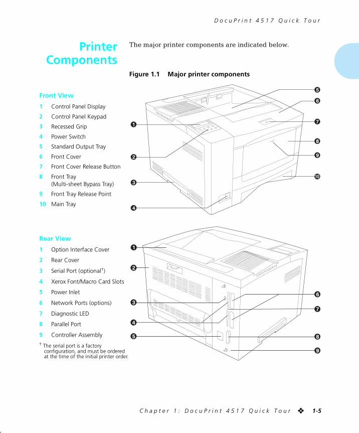
PrinterComponents
The major printer components are indicated below.
Figure 1.1 Major printer components
Front View
1 Control Panel Display
2 Control Panel Keypad
3 Recessed Grip
4 Power Switch
5 Standard Output Tray
6 Front Cover
7 Front Cover Release Button
8 Front Tray (Multi-sheet Bypass Tray)
9 Front Tray Release Point
10 Main Tray
Rear View
1 Option Interface Cover
2 Rear Cover
3 Serial Port (optional†)
4 Xerox Font/Macro Card Slots
5 Power Inlet
6 Network Ports (options)
7 Diagnostic LED
8 Parallel Port
9 Controller Assembly† The serial port is a factory
configuration, and must be ordered at the time of the initial printer order.
chapter1.frm Page 5 Friday, July 11, 1997 8:12 PM
D o c u P r i n t 4 5 1 7 Q u i c k T o u r
1-6 ❖ D o c u P r i n t 4 5 1 7 / 4 5 1 7 m p U s e r G u i d e
SpecialFeatures
Several features have been designed into the DocuPrint 4517
to enhance your printing environment. Using the printer’s Control Panel menu system, you can tailor printer settings to match your printing requirements.
See Chapter 3: Using the Control Panel for more information about the Control Panel and its menu system.
Power Saver After 60 minutes of inactivity, the printer automatically turns off internal components to reduce the amount of electricity
used. The printer automatically turns those parts back on when it receives a print job.
Using the printer’s Control Panel menu system, you can send the printer into Power Saver mode after your choice of 15, 30,
60, 90 or 120 minutes of inactivity (or Power Saver mode can be disabled).
See the section “System Menu” (page 3-30) in
Chapter 3: Using the Control Panel.
High ResolutionPrinting
The DocuPrint 4517 is set to print at 600 x 600 dpi (dots per
inch). You can change this setting to 1200 x 600 dpi to enhance grayscale images.
For professional quality printouts, the Print Quality option (in
the PCL Emulat and PostScript menus) may be set to TrueRes (for 600 x 600 resolution printing). The TrueRes setting smooths edges to produce a crisper looking printout.
If you want to print draft-quality jobs, set Print Quality to
Toner Saving. The printer automatically reduces the amount of toner used (and prints a lower density output). When this feature is enabled, the printer will print with 62.5% less toner.
See Chapter 3: Using the Control Panel for instructions on changing Control Panel settings.
chapter1.frm Page 6 Friday, July 11, 1997 8:12 PM
S p e c i a l F e a t u r e s
C h a p t e r 1 : D o c u P r i n t 4 5 1 7 Q u i c k T o u r ❖ 1-7
Edge to EdgePrinting
For those instances when you need to print PCL 5e Emulation
(hereafter referred to as PCL) jobs all the way to the edge of the page, turn on the Edge to Edge option in the PCL Emulat Menu. Edge to edge printing is always available for
PostScript jobs and requires no setting. Just format your document to the edge of the page.
See Chapter 3: Using the Control Panel for instructions on
changing Control Panel settings.
Automatic TraySwitching
The DocuPrint 4517 allows you to set automatic tray switching for both PCL and PostScript (when PostScript is installed) jobs. When tray switching is on, and the paper tray
runs out of paper, the printer automatically switches to another paper tray (if another tray is loaded with the same size paper). That means you don’t have to load paper as often.
You can also install one or two optional 500-sheet Paper Deck and Cassettes (lower trays), or the 2,000-sheet High Capacity Feeder, to extend your printing capacity.
For more information on tray switching, see the section
“Automatic Tray Switching” (page 2-18) in Chapter 2: Paper Handling.
AutomaticLanguage Sensing
and Switching
When you have installed the PostScript option, the printer can process both PCL and PostScript jobs. When the printer’s
Language Sensing option is on, the DocuPrint 4517 samples the incoming data stream to determine which language the print job requires. The DocuPrint 4517 then switches to the
proper language for that job.
The DocuPrint 4517 can have up to three active ports when you install two optional network interface cards. Turn the Language Sensing option on for all the ports, and the printer
automatically samples each print job and switches to the appropriate processing language.
For more information about language sensing and switching,
see Appendix D: Control Panel Options.
chapter1.frm Page 7 Friday, July 11, 1997 8:12 PM
S p e c i a l F e a t u r e s
1-8 ❖ D o c u P r i n t 4 5 1 7 / 4 5 1 7 m p U s e r G u i d e
State Saving When you are printing both PostScript and PCL jobs, the
printer clears any downloaded fonts, macros, and PostScript headers when it switches between PostScript and PCL 5e Emulation. However, you can set the printer’s State Saving
option to On, and the printer will save downloaded fonts, macros, and PostScript headers when it switches PDLs (Printer Description Language). This saves you from having
to download fonts, macros, and headers every time the printer switches between PostScript and PCL 5e Emulation.
Printer GeneratedReports
Using the printer’s Control Panel, you can print five separate
reports.
• The Demo Page provides a sample of the printer’s capabilities and lists the printer’s key features.
• The Configuration Sheet lists the options you have
installed and the current settings for each option in the Control Panel’s menu system.
• The PCL Font List shows which PCL fonts are currently
available. The list includes resident fonts, fonts on font cards, and downloaded fonts.
• When PostScript is installed on the DocuPrint 4517, the PostScript Font List shows which PostScript fonts are
currently available. The list includes both resident and downloaded fonts.
• The Test Print is used by service and repair technicians if
problems occur with the printer.
See Appendix D: Control Panel Options for more information about these reports.
Note
State Saving uses printer memory or the optional Hard Drive to save these objects. Refer to “Memory Considerations” (page 1-11).
chapter1.frm Page 8 Friday, July 11, 1997 8:12 PM
S p e c i a l F e a t u r e s
C h a p t e r 1 : D o c u P r i n t 4 5 1 7 Q u i c k T o u r ❖ 1-9
PostScriptUpgrades
Upgrading your printer with PostScript Level 2 is
accomplished by adding the PostScript SIMM.
See Appendix A: Ordering Printer Options to order PostScript.
Duplex Printing The DocuPrint 4517 can print two-sided documents when you
install the optional Duplex Module. After installing the Duplex Module and a DocuPrint 4517 printer driver, printing a two-sided document is as easy as printing a one-sided job.
See Appendix A: Ordering Printer Options to order a Duplex
Module.
Increased PaperHandling
An optional 500-sheet lower tray (the 500-sheet Paper Deck and Cassette), and a 2,000-sheet High Capacity Feeder (HCF) are available for the DocuPrint 4517. Install two lower
trays and you increase the input capacity for the DocuPrint 4517 by 1,000 sheets. One 500-sheet Paper Deck may be installed with the HCF to increase input capacity by 2,500
sheets.
See Appendix A: Ordering Printer Options to order a 500-sheet Paper Deck and Cassette, or the HCF.
Collating andOffsetting
Two optional output trays are available for the DocuPrint 4517 that provide a second output destination for your print jobs.
Send your print job to the standard output tray or either optional output device.
• The Offset Catch Tray (OCT) sits above the standard output tray. It increases the output tray capacity for the
printer and offsets jobs from each other.
• The Mailbox/Collator sits atop the standard output tray and collates multiple copies or separates your jobs into 10
separate bins. For privacy, set passwords for the bins.
See Chapter 2: Paper Handling for more information about using the Offset Catch Tray and Mailbox/Collator.
chapter1.frm Page 9 Friday, July 11, 1997 8:12 PM
S p e c i a l F e a t u r e s
1-10 ❖ D o c u P r i n t 4 5 1 7 / 4 5 1 7 m p U s e r G u i d e
See Appendix A: Ordering Printer Options to order an Offset
Catch Tray or a Mailbox/Collator.
MemoryExpansion
The DocuPrint 4517 Version 2.0 base printer has 4 MB of resident memory (systems prior to Version 2.0 have 2 MB of base memory) and can be increased with available 4 MB, 16
MB, and 32 MB SIMMs.
A hard drive is also available for the printer. The hard drive can be used for print spooling, font storage, macro storage,
and state saving.
See Chapter 5: Using the Hard Drive / Downloading Fonts for more information about the hard drive.
See Appendix A: Ordering Printer Options to order more
printer memory or a hard drive.
chapter1.frm Page 10 Friday, July 11, 1997 8:12 PM
D o c u P r i n t 4 5 1 7 Q u i c k T o u r
C h a p t e r 1 : D o c u P r i n t 4 5 1 7 Q u i c k T o u r ❖ 1-11
MemoryConsiderations
In today’s printing environments, technologies have
advanced greatly. Corresponding memory requirements have also increased.
• DocuPrint 4517 printing features such as Page Protection
and State Saving, when on, use available printer memory—memory that is otherwise used for processing jobs.
• Downloading fonts also uses available printer memory.
• Installation of the Hard Drive option or Network Interface Card(s) will slightly increase memory needs due to memory buffer allocations.
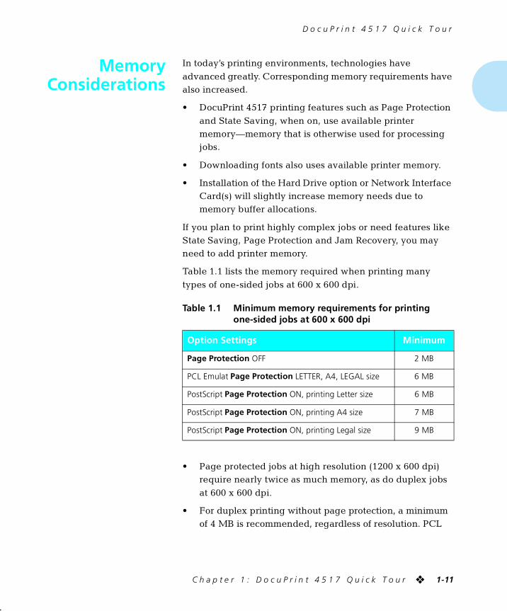
If you plan to print highly complex jobs or need features like State Saving, Page Protection and Jam Recovery, you may need to add printer memory.
Table 1.1 lists the memory required when printing many
types of one-sided jobs at 600 x 600 dpi.
• Page protected jobs at high resolution (1200 x 600 dpi) require nearly twice as much memory, as do duplex jobs
at 600 x 600 dpi.
• For duplex printing without page protection, a minimum of 4 MB is recommended, regardless of resolution. PCL
Table 1.1 Minimum memory requirements for printing one-sided jobs at 600 x 600 dpi
Option Settings Minimum
Page Protection OFF 2 MB
PCL Emulat Page Protection LETTER, A4, LEGAL size 6 MB
PostScript Page Protection ON, printing Letter size 6 MB
PostScript Page Protection ON, printing A4 size 7 MB
PostScript Page Protection ON, printing Legal size 9 MB
chapter1.frm Page 11 Friday, July 11, 1997 8:12 PM
M e m o r y C o n s i d e r a t i o n s
1-12 ❖ D o c u P r i n t 4 5 1 7 / 4 5 1 7 m p U s e r G u i d e
requires the extra memory for duplex whenever the
duplex unit is installed, even if printing simplex.
• Printing speed of complex jobs, such as those containing extensive graphics or font use, will generally be improved
by adding memory beyond the minimums described here.
• Either 1 MB or 4 MB of the printer’s memory (depending on the version of the printer) may become unusable when
2-sided 32 MB SIMMs are installed (or other non-Xerox 2-sided SIMMs, such as 8 MB or 2 MB). Thus the total system memory may be less than the sum of resident and
SIMM memory when 2-sided SIMMS are used. To maximize usable memory, we suggest selecting slot SIMM3 for a 2-sided SIMM and not using 2 MB SIMMs in
slot SIMM2.
For further recommendations to best determine the memory required for your DocuPrint 4517, please contact Xerox/Rank Xerox or your dealer.
chapter1.frm Page 12 Friday, July 11, 1997 8:12 PM
D o c u P r i n t 4 5 1 7 Q u i c k T o u r
C h a p t e r 1 : D o c u P r i n t 4 5 1 7 Q u i c k T o u r ❖ 1-13
Maintainingthe Printer
Maintaining the printer in good operating condition is
essential to having a reliable, well-running machine.
Cleaning thePrinter
For optimum performance, do not place the printer near vents or dust-producing equipment. Particles in the air may enter
the printer and cause failures in internal mechanisms.
For best results, clean the outside of the printer with a damp cloth. Power the printer off before cleaning. Do not use
detergents.
Replacing theEP Cartridge
An EP (electronic printing) cartridge will print approximately
10,000 pages of A4 or 8.5 x 11 paper under average operating conditions (5% image area coverage). The number of prints per cartridge will decrease if you routinely:
• Print dense text and graphics.
• Set Print Density (in the System Menu) to a dark setting.
• Exceed five percent area coverage.
You may increase the number of prints per cartridge by setting Print Quality to Toner Saving. The printer
automatically reduces the amount of toner used (and prints a lower density output). See Chapter 3: Using the Control Panel for instructions on changing Control Panel settings.
Replace the EP cartridge when you see the following message at the printer’s Control Panel display:
Toner Low
Although you can print for a short time after this message first
appears, to ensure optimum print quality you should replace the EP cartridge as soon as possible.
See Appendix A: Ordering Printer Options for ordering a new EP cartridge.
chapter1.frm Page 13 Friday, July 11, 1997 8:12 PM
M a i n t a i n i n g t h e P r i n t e r
1-14 ❖ D o c u P r i n t 4 5 1 7 / 4 5 1 7 m p U s e r G u i d e
Recycling theEP Cartridge
The DocuPrint 4517 EP cartridge can be recycled free of
charge to you. Follow the instructions packaged with your new EP cartridge to recycle the old one.
Replacing theFuser Cartridge/
Bias Transfer Roll
The Fuser Cartridge and Bias Transfer Roll (BTR) have expected useful lives of 200,000 prints. When this point is
reached, you will see the following message at the printer’s Control Panel display:
Replace
Fuser Cartridge
Although printing can continue, to ensure optimum print quality, you should order and replace these parts as soon as possible.
See Appendix A: Ordering Printer Options for ordering information.
chapter1.frm Page 14 Friday, July 11, 1997 8:12 PM
D o c u P r i n t 4 5 1 7 Q u i c k T o u r
C h a p t e r 1 : D o c u P r i n t 4 5 1 7 Q u i c k T o u r ❖ 1-15
TechnicalSupport
If you are unable to resolve a printing problem using the
instructions in Chapter 6: Troubleshooting, contact the dealer from which you bought your printer or contact Xerox/Rank Xerox.
Before Callingfor Service
Before contacting your dealer or Xerox/Rank Xerox, please
have the following information available:
• Printer Serial No. (located on inside right side of machine after opening the front cover)
• A Configuration Sheet (follow instructions in Step 9 on
page C-17)
• Any error code or message displayed on the Control Panel
• A description of the problem
• Type of network (if problem is network related)
chapter1.frm Page 15 Friday, July 11, 1997 8:12 PM
D o c u P r i n t 4 5 1 7 Q u i c k T o u r
1-16 ❖ D o c u P r i n t 4 5 1 7 / 4 5 1 7 m p U s e r G u i d e
Transportingthe Printer
When transporting the printer more than a short distance, use
the original shipping box and packaging materials. If the original shipping box or packaging materials are not available, use a sturdy packing box and a generous amount of
cushioning or packing materials.
To prepare your printer for transportation, follow the instructions below.
If you need to return the printer for service, follow the
instructions of your service provider for packing and shipping.
1 Power off the printer and disconnect the power cord and all interface cables.
2 Remove any paper handling options and repack each in its original packaging.
3 Remove the hard drive (if it is installed), and repack it in its original packaging. See Appendix C: Installing and Removing Printer Options.
4 Remove the EP cartridge and pack it in its original packaging.
5 Pack the printer with the sealed EP cartridge and power cord in the original printer box.
chapter1.frm Page 16 Friday, July 11, 1997 8:12 PM
Chapter 2
C h a p t e r 2 : P a p e r H a n d l i n g ❖ 2-1
Paper Handling Chapter2
Selecting Paper ..................................................................... 2-3
Storing Paper ........................................................................ 2-5
Loading Paper ....................................................................... 2-6
Using the Main Tray ............................................................. 2-6
Using the Front Tray ............................................................. 2-8
Using the 500-sheet Paper Deck and Cassette .................... 2-12
Using the High Capacity Feeder .......................................... 2-14
Using the Envelope Feeder ................................................. 2-16
Automatic Tray Switching ................................................. 2-18
PostScript Tray Switching .................................................... 2-18
PCL Tray Switching (Source Mapping) ................................. 2-19
Default Source Mapping Settings .................................... 2-21
Customizing Source Mapping Settings ............................ 2-21
Example: Main Tray-Front Tray ........................................ 2-22
Example: Lower Tray-Main Tray ....................................... 2-23
chapter2.frm Page 1 Friday, July 11, 1997 8:13 PM

P a p e r H a n d l i n g
2-2 ❖ D o c u P r i n t 4 5 1 7 / 4 5 1 7 m p U s e r G u i d e
Using the Mailbox/Collator ................................................ 2-24
Printing to the Mailbox/Collator .......................................... 2-25
Password Protecting Jobs ................................................... 2-25
Enabling Passwords ......................................................... 2-26
Disabling Passwords ........................................................ 2-28
Opening Bins ...................................................................... 2-31
Opening Password-Enabled Bins ...................................... 2-31
Opening Password-Disabled Bins ..................................... 2-31
Using the Offset Catch Tray (OCT) .................................... 2-32
Duplex (Two-Sided) Printing ............................................. 2-33
Print Orientation and Control Panel Settings ....................... 2-34
chapter2.frm Page 2 Friday, July 11, 1997 8:13 PM
P a p e r H a n d l i n g
C h a p t e r 2 : P a p e r H a n d l i n g ❖ 2-3
SelectingPaper
Table 2.1 on page 2-4 lists the size paper, envelopes, and
other print media you can use with all DocuPrint 4517 input and output trays. Using sizes other than those listed in Table 2.1, or paper not recommended for laser printers, may
result in paper jams.
The DocuPrint 4517 supports paper weights as follows:
• 16-28 lbs. (60-105 gsm) via paper trays
• 16-28 lbs. (60-105 gsm) and A6 international postcard
(190 gsm) via the front tray
• 17-24 lbs. (64-90 gsm) with duplex
• The optional HCF supports 18-24 lbs. (68-90 gsm).
chapter2.frm Page 3 Friday, July 11, 1997 8:13 PM
S e l e c t i n g P a p e r
2-4 ❖ D o c u P r i n t 4 5 1 7 / 4 5 1 7 m p U s e r G u i d e
† Optional 500-sheet or 2,000-sheet paper handler. See Appendix A for ordering information.
‡ Although the OCT will accept all paper sizes listed, it can only offset A4, Letter, Folio, and Legal.
†† Only the main tray accepts Executive.
Table 2.1 Acceptable paper sizes for all DocuPrint 4517 paper trays
Paper Size
Input Output
Main Tray,Lower Tray†
and HCF†Front Tray
Envelope Feeder†
Standard Output Tray and
OCT†‡
Mailbox / Collator†
A4 (210x297mm) • • • •
Letter (8.5x11” / 216x279mm) • • • •
Folio (8.5x13” / 216x330mm) • • •
Legal (8.5x14” / 216x356mm) • • •
Executive (7.25x10.5” / 184x267mm) †† • •
Statement (5.5x8.5” / 140x216mm) • •
ISO B5 (176x250mm) • •
EnvelopeCOM-10 (4.12x9.5” / 105x241mm)Monarch (3.87x7.5” / 98x191mm)DL (4.33x8.66” / 110x220mm)C5 (6.38x9.01” / 162x229mm)C6 (4.49x6.38” / 114x162mm)
•••••
•••••
•••••
TransparencyA4 (210x297 mm)Letter (8.5x11” / 216x279mm)
••
••
LabelA4 (210x297 mm)Letter (8.5x11” / 216x279mm)
••
••
A6 (International Postcard)(105 x 148mm)
• •
chapter2.frm Page 4 Friday, July 11, 1997 8:13 PM
P a p e r H a n d l i n g
C h a p t e r 2 : P a p e r H a n d l i n g ❖ 2-5
Storing Paper The DocuPrint 4517’s print quality is optimized when paper
and other print media are properly stored. Proper storage ensures optimum print quality and trouble-free printer options.
• Store the paper on a flat surface, in a relatively low humidity environment.
• Do not unwrap paper until you are ready to use it, and
rewrap any paper you are not using.
• Do not expose paper to direct sunlight or high humidity.
chapter2.frm Page 5 Friday, July 11, 1997 8:13 PM
P a p e r H a n d l i n g
2-6 ❖ D o c u P r i n t 4 5 1 7 / 4 5 1 7 m p U s e r G u i d e
Loading Paper The DocuPrint 4517 accepts paper into its main tray (see
below), front tray (see page 2-8), optional 500-sheet Paper Deck and Cassette (see page 2-12), optional 2,000-sheet High Capacity Feeder (see page 2-14), and optional Envelope
Feeder (see page 2-16).
Using theMain Tray
The main tray holds 250 sheets of 20 lb (75 g/m2) paper. Refer to the section “Selecting Paper” (page 2-3) for acceptable paper sizes and weights.
Caution
• Do not attempt to load the main tray during printing.
• Do not overfill the tray.
1 Press down on the bottom plate of the paper tray until it clicks into position.
If you are not changing paper size, go to Step 4 on page 2-7. Otherwise, continue to Step 2.
If you are changing to a smaller size, perform Steps 2 and 3 in reverse order.
2 Push in on the size lock button (1) and slide end guide A (2) out.
chapter2.frm Page 6 Friday, July 11, 1997 8:13 PM
L o a d i n g P a p e r
C h a p t e r 2 : P a p e r H a n d l i n g ❖ 2-7
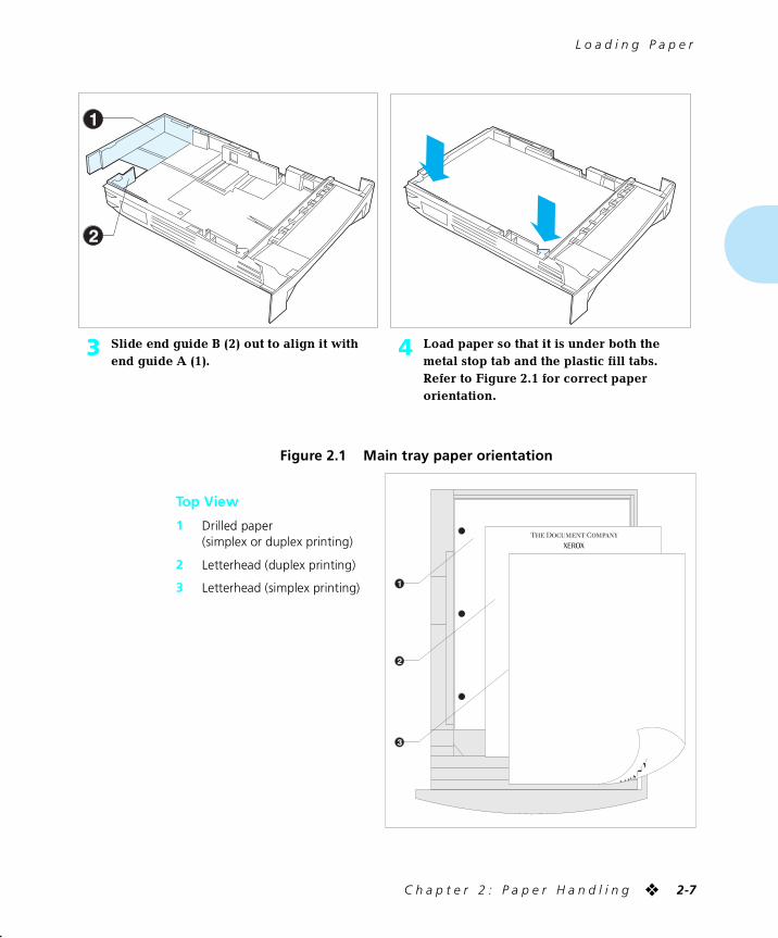
3 Slide end guide B (2) out to align it with end guide A (1).
4 Load paper so that it is under both the metal stop tab and the plastic fill tabs. Refer to Figure 2.1 for correct paper orientation.
Figure 2.1 Main tray paper orientation
Top View
1 Drilled paper(simplex or duplex printing)
2 Letterhead (duplex printing)
3 Letterhead (simplex printing)
chapter2.frm Page 7 Friday, July 11, 1997 8:13 PM
L o a d i n g P a p e r
2-8 ❖ D o c u P r i n t 4 5 1 7 / 4 5 1 7 m p U s e r G u i d e
Using theFront Tray
The front tray accepts all paper sizes, weights and types listed
in the section “Selecting Paper” (page 2-3).
The front tray holds:
• 100 sheets of 20 lb (75 g/m2) paper
• 30 transparencies or 25 sheets of label paper
• 10 envelopes
Consult Figure 2.2 for proper orientation of letterhead and drilled paper in the front tray, and Figure 2.3 for proper orientation of envelopes and postcards in the front tray.
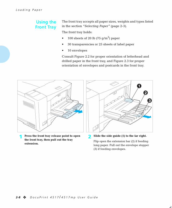
1 Press the front tray release point to open the front tray, then pull out the tray extension.
2 Slide the side guide (1) to the far right.
Flip open the extension bar (2) if feeding long paper. Pull out the envelope stopper (3) if feeding envelopes.
chapter2.frm Page 8 Friday, July 11, 1997 8:13 PM
L o a d i n g P a p e r
C h a p t e r 2 : P a p e r H a n d l i n g ❖ 2-9
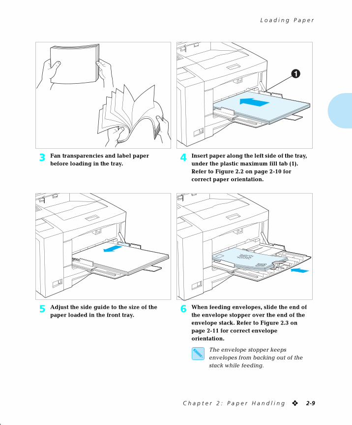
3 Fan transparencies and label paper before loading in the tray.
4 Insert paper along the left side of the tray, under the plastic maximum fill tab (1). Refer to Figure 2.2 on page 2-10 for correct paper orientation.
5 Adjust the side guide to the size of the paper loaded in the front tray.
6 When feeding envelopes, slide the end of the envelope stopper over the end of the envelope stack. Refer to Figure 2.3 on page 2-11 for correct envelope orientation.
The envelope stopper keeps envelopes from backing out of the stack while feeding.
chapter2.frm Page 9 Friday, July 11, 1997 8:13 PM
L o a d i n g P a p e r
2-10 ❖ D o c u P r i n t 4 5 1 7 / 4 5 1 7 m p U s e r G u i d e
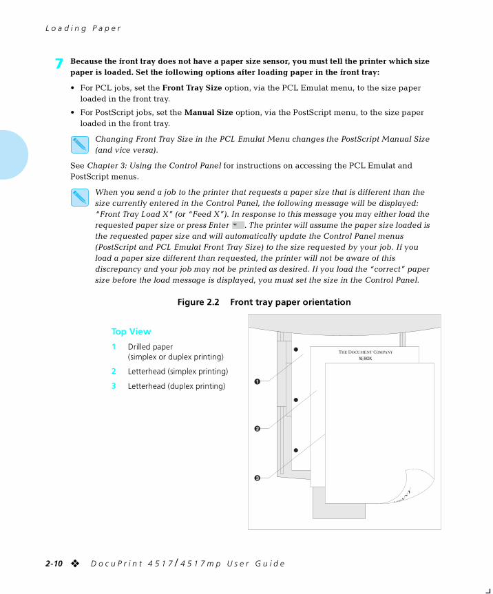
7 Because the front tray does not have a paper size sensor, you must tell the printer which size paper is loaded. Set the following options after loading paper in the front tray:
• For PCL jobs, set the Front Tray Size option, via the PCL Emulat menu, to the size paper loaded in the front tray.
• For PostScript jobs, set the Manual Size option, via the PostScript menu, to the size paper loaded in the front tray.
Changing Front Tray Size in the PCL Emulat Menu changes the PostScript Manual Size (and vice versa).
See Chapter 3: Using the Control Panel for instructions on accessing the PCL Emulat and PostScript menus.
When you send a job to the printer that requests a paper size that is different than the size currently entered in the Control Panel, the following message will be displayed: “Front Tray Load X” (or “Feed X”). In response to this message you may either load the requested paper size or press Enter . The printer will assume the paper size loaded is the requested paper size and will automatically update the Control Panel menus (PostScript and PCL Emulat Front Tray Size) to the size requested by your job. If you load a paper size different than requested, the printer will not be aware of this discrepancy and your job may not be printed as desired. If you load the “correct” paper size before the load message is displayed, you must set the size in the Control Panel.
Figure 2.2 Front tray paper orientation
Top View
1 Drilled paper(simplex or duplex printing)
2 Letterhead (simplex printing)
3 Letterhead (duplex printing)
chapter2.frm Page 10 Friday, July 11, 1997 8:13 PM
L o a d i n g P a p e r
C h a p t e r 2 : P a p e r H a n d l i n g ❖ 2-11
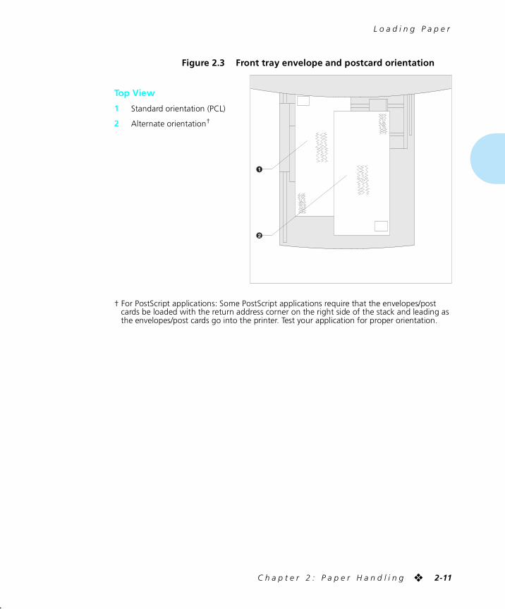
† For PostScript applications: Some PostScript applications require that the envelopes/post cards be loaded with the return address corner on the right side of the stack and leading as the envelopes/post cards go into the printer. Test your application for proper orientation.
Figure 2.3 Front tray envelope and postcard orientation
Top View
1 Standard orientation (PCL)
2 Alternate orientation†
chapter2.frm Page 11 Friday, July 11, 1997 8:13 PM
L o a d i n g P a p e r
2-12 ❖ D o c u P r i n t 4 5 1 7 / 4 5 1 7 m p U s e r G u i d e
Using the500-sheet Paper
Deck and Cassette
The optional 500-sheet Paper Deck and Cassette holds 500
sheets of 20 lb (75 g/m2) paper. Refer to the section “Selecting Paper” (page 2-3) for acceptable paper sizes and weights.
(See Appendix A for ordering information and Appendix C
for installation instructions.)
Caution
• Do not attempt to load the 500-sheet Paper Deck and Cassette during printing.
• Do not overfill the paper cassette.
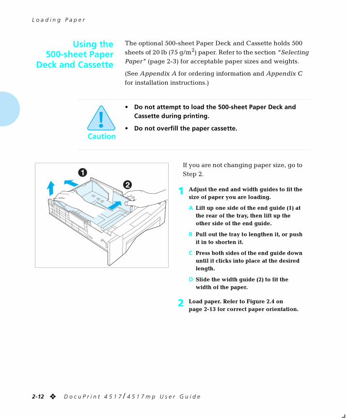
If you are not changing paper size, go to Step 2.
1 Adjust the end and width guides to fit the size of paper you are loading.
A Lift up one side of the end guide (1) at the rear of the tray, then lift up the other side of the end guide.
B Pull out the tray to lengthen it, or push it in to shorten it.
C Press both sides of the end guide down until it clicks into place at the desired length.
D Slide the width guide (2) to fit the width of the paper.
2 Load paper. Refer to Figure 2.4 on page 2-13 for correct paper orientation.
chapter2.frm Page 12 Friday, July 11, 1997 8:13 PM
L o a d i n g P a p e r
C h a p t e r 2 : P a p e r H a n d l i n g ❖ 2-13
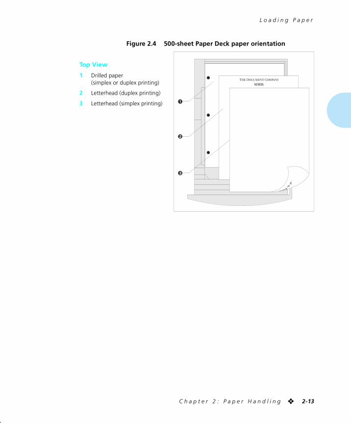
Figure 2.4 500-sheet Paper Deck paper orientation
Top View
1 Drilled paper(simplex or duplex printing)
2 Letterhead (duplex printing)
3 Letterhead (simplex printing)
chapter2.frm Page 13 Friday, July 11, 1997 8:13 PM
L o a d i n g P a p e r
2-14 ❖ D o c u P r i n t 4 5 1 7 / 4 5 1 7 m p U s e r G u i d e
Using theHigh Capacity
Feeder
The optional High Capacity Feeder (HCF) holds 2,000 sheets
of 20 lb (75 g/m2) paper. Refer to the section “Selecting Paper” (page 2-3) for acceptable paper sizes and weights.
(See Appendix A for ordering information and Appendix C
for installation instructions.)
Note
When the HCF is installed, it can be accessed using your
existing applications/drivers as a “Lower Tray.”
Caution
• Do not attempt to load the High Capacity Feeder during printing.
• Do not overfill the feeder.
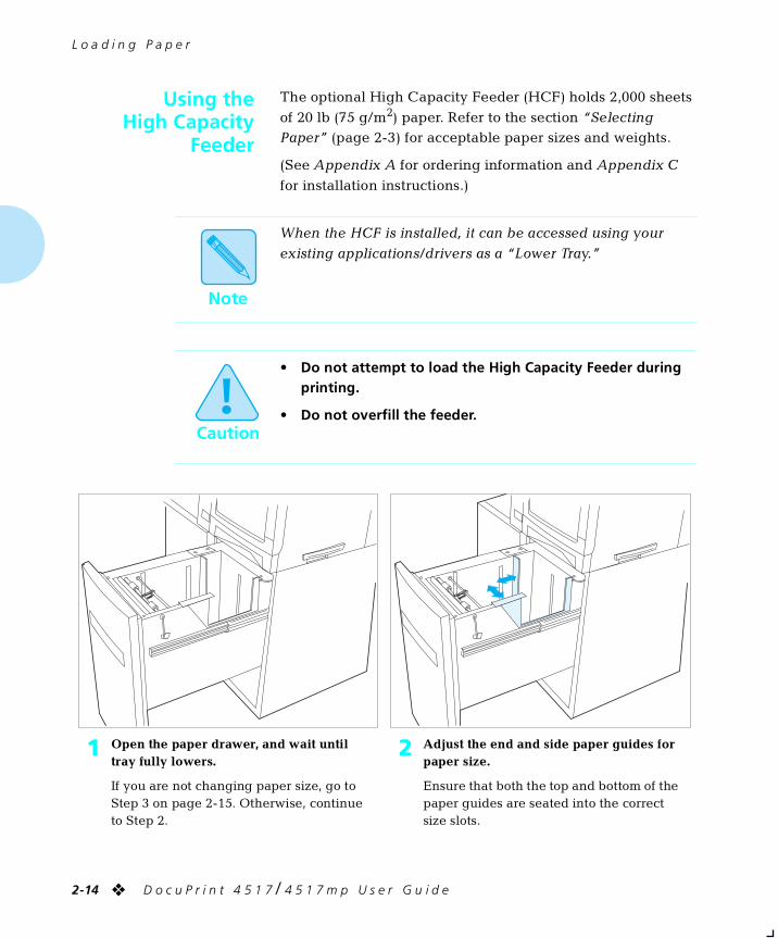
1 Open the paper drawer, and wait until tray fully lowers.
If you are not changing paper size, go to Step 3 on page 2-15. Otherwise, continue to Step 2.
2 Adjust the end and side paper guides for paper size.
Ensure that both the top and bottom of the paper guides are seated into the correct size slots.
chapter2.frm Page 14 Friday, July 11, 1997 8:13 PM
L o a d i n g P a p e r
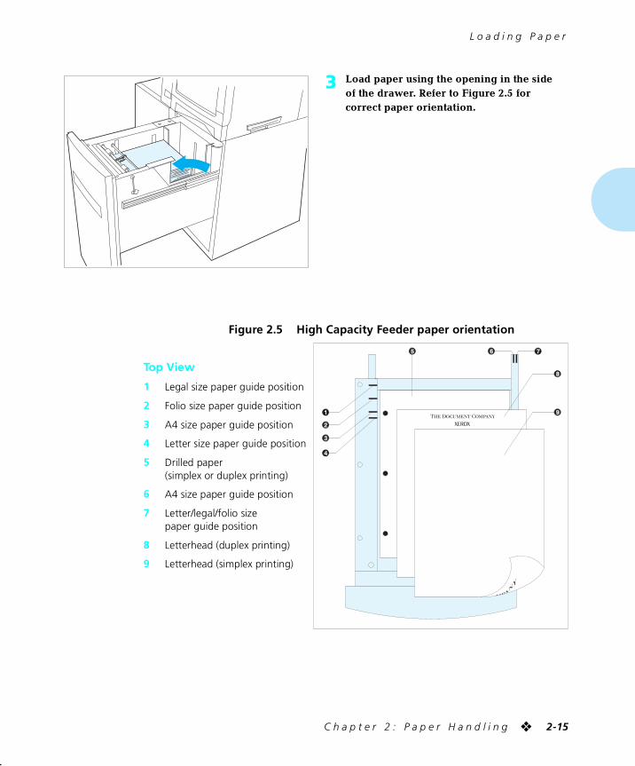
C h a p t e r 2 : P a p e r H a n d l i n g ❖ 2-15
3 Load paper using the opening in the side of the drawer. Refer to Figure 2.5 for correct paper orientation.
Figure 2.5 High Capacity Feeder paper orientation
Top View
1 Legal size paper guide position
2 Folio size paper guide position
3 A4 size paper guide position
4 Letter size paper guide position
5 Drilled paper(simplex or duplex printing)
6 A4 size paper guide position
7 Letter/legal/folio size paper guide position
8 Letterhead (duplex printing)
9 Letterhead (simplex printing)
chapter2.frm Page 15 Friday, July 11, 1997 8:13 PM
L o a d i n g P a p e r
2-16 ❖ D o c u P r i n t 4 5 1 7 / 4 5 1 7 m p U s e r G u i d e
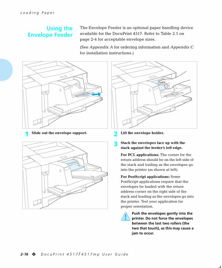
Using theEnvelope Feeder
The Envelope Feeder is an optional paper handling device
available for the DocuPrint 4517. Refer to Table 2.1 on page 2-4 for acceptable envelope sizes.
(See Appendix A for ordering information and Appendix C
for installation instructions.)
1 Slide out the envelope support. 2 Lift the envelope holder.
3 Stack the envelopes face up with the stack against the feeder’s left edge.
For PCL applications: The corner for the return address should be on the left side of the stack and trailing as the envelopes go into the printer (as shown at left).
For PostScript applications: Some PostScript applications require that the envelopes be loaded with the return address corner on the right side of the stack and leading as the envelopes go into the printer. Test your application for proper orientation.
Push the envelopes gently into the printer. Do not force the envelopes between the last two rollers (the two that touch), as this may cause a jam to occur.
chapter2.frm Page 16 Friday, July 11, 1997 8:13 PM
L o a d i n g P a p e r
C h a p t e r 2 : P a p e r H a n d l i n g ❖ 2-17
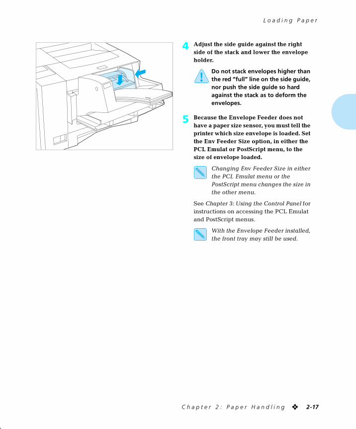
4 Adjust the side guide against the right side of the stack and lower the envelope holder.
Do not stack envelopes higher than the red “full” line on the side guide, nor push the side guide so hard against the stack as to deform the envelopes.
5 Because the Envelope Feeder does not have a paper size sensor, you must tell the printer which size envelope is loaded. Set the Env Feeder Size option, in either the PCL Emulat or PostScript menu, to the size of envelope loaded.
Changing Env Feeder Size in either the PCL Emulat menu or the PostScript menu changes the size in the other menu.
See Chapter 3: Using the Control Panel for instructions on accessing the PCL Emulat and PostScript menus.
With the Envelope Feeder installed, the front tray may still be used.
chapter2.frm Page 17 Friday, July 11, 1997 8:13 PM
P a p e r H a n d l i n g
2-18 ❖ D o c u P r i n t 4 5 1 7 / 4 5 1 7 m p U s e r G u i d e
AutomaticTray Switching
Automatic tray switching is available for both PCL emulation
and PostScript jobs. Tray switching is useful for:
• Increasing paper capacity.
When the current paper tray runs out of paper, the printer automatically switches to the next tray in the sequence,
provided the paper size in the next tray is the same size as that in the current tray.
• Searching for the correct paper size.
If the paper size specified in your software application does not match the size paper loaded in the current paper tray, the printer automatically searches the next tray in
the sequence for a paper size that matches.
PostScript TraySwitching
The Tray Switching option (in the PostScript Menu) can be
set to any of the settings shown in Table 2.2 below.
For example, when Tray Switching is off, no tray switching occurs. When set to Main-Front the printer automatically switches to the front tray when the main tray becomes empty
(provided the correct size paper is in both trays).
† Version 2.0 or later.
Table 2.2 Tray switching settings
Tray Switching Setting Description
OffMain-Front TrayFront-Main Tray†
Tray sequence to be used for PostScript jobs
Lower 1-MainFront-Lower 1†
Additional Tray Switching settings that appear when a 500-sheet Paper Deck and Cassette or 2,000-sheet High Capacity Feeder is installed
Lower 2-MainLower 1-Lower 2Lwr1-Lwr2-MainFront-Lower 2†
Additional Tray Switching settings that appear when a second Lower Tray (500-sheet Paper Deck and Cassette or 2,000-sheet High Capacity Feeder) is installed
chapter2.frm Page 18 Friday, July 11, 1997 8:13 PM
A u t o m a t i c T r a y S w i t c h i n g
C h a p t e r 2 : P a p e r H a n d l i n g ❖ 2-19
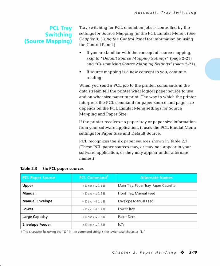
PCL TraySwitching
(Source Mapping)
Tray switching for PCL emulation jobs is controlled by the
settings for Source Mapping (in the PCL Emulat Menu). (See Chapter 3: Using the Control Panel for information on using the Control Panel.)
• If you are familiar with the concept of source mapping, skip to “Default Source Mapping Settings” (page 2-21) and “Customizing Source Mapping Settings” (page 2-21).
• If source mapping is a new concept to you, continue reading.
When you send a PCL job to the printer, commands in the data stream tell the printer what logical paper source to use
and on what size paper to print. The way in which the printer interprets the PCL command for paper source and page size depends on the PCL Emulat Menu settings for Source
Mapping and Paper Size.
If the printer receives no paper tray or paper size information from your software application, it uses the PCL Emulat Menu
settings for Paper Size and Default Source.
PCL recognizes the six paper sources shown in Table 2.3. (These PCL paper sources may, or may not, appear in your software application, or they may appear under alternate
names.)
† The character following the “&” in the command string is the lower case character “L.”
Table 2.3 Six PCL paper sources
PCL Paper Source PCL Command† Alternate Names
Upper <Esc>& l1H Main Tray, Paper Tray, Paper Cassette
Manual <Esc>& l2H Front Tray, Manual Feed
Manual Envelope <Esc>& l3H Envelope Manual Feed
Lower <Esc>& l4H Lower Tray
Large Capacity <Esc>& l5H Paper Deck
Envelope Feeder <Esc>& l6H N/A
chapter2.frm Page 19 Friday, July 11, 1997 8:13 PM
A u t o m a t i c T r a y S w i t c h i n g
2-20 ❖ D o c u P r i n t 4 5 1 7 / 4 5 1 7 m p U s e r G u i d e
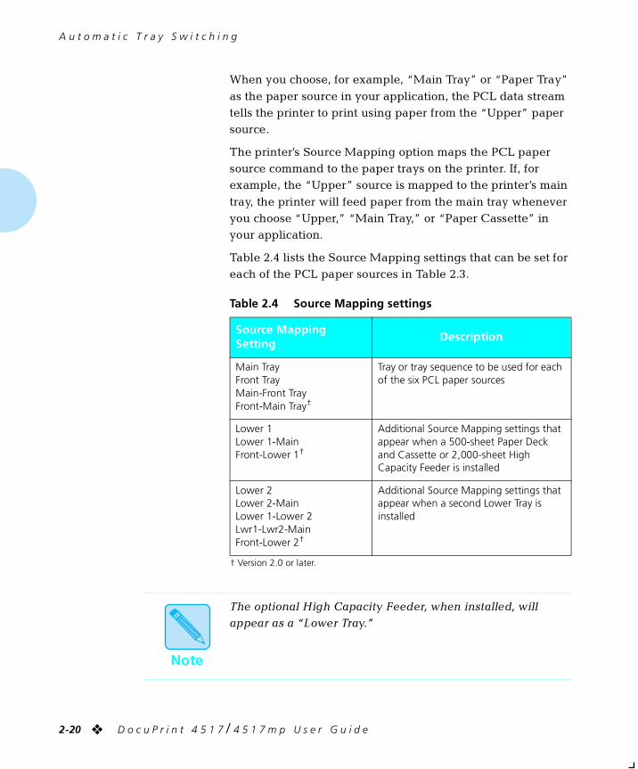
When you choose, for example, “Main Tray” or “Paper Tray”
as the paper source in your application, the PCL data stream tells the printer to print using paper from the “Upper” paper source.
The printer’s Source Mapping option maps the PCL paper source command to the paper trays on the printer. If, for example, the “Upper” source is mapped to the printer’s main
tray, the printer will feed paper from the main tray whenever you choose “Upper,” “Main Tray,” or “Paper Cassette” in your application.
Table 2.4 lists the Source Mapping settings that can be set for each of the PCL paper sources in Table 2.3.
† Version 2.0 or later.
Table 2.4 Source Mapping settings
Source Mapping Setting
Description
Main TrayFront TrayMain-Front TrayFront-Main Tray†
Tray or tray sequence to be used for each of the six PCL paper sources
Lower 1Lower 1-MainFront-Lower 1†
Additional Source Mapping settings that appear when a 500-sheet Paper Deck and Cassette or 2,000-sheet High Capacity Feeder is installed
Lower 2Lower 2-MainLower 1-Lower 2Lwr1-Lwr2-MainFront-Lower 2†
Additional Source Mapping settings that appear when a second Lower Tray is installed
Note
The optional High Capacity Feeder, when installed, will appear as a “Lower Tray.”
chapter2.frm Page 20 Friday, July 11, 1997 8:13 PM
A u t o m a t i c T r a y S w i t c h i n g
C h a p t e r 2 : P a p e r H a n d l i n g ❖ 2-21
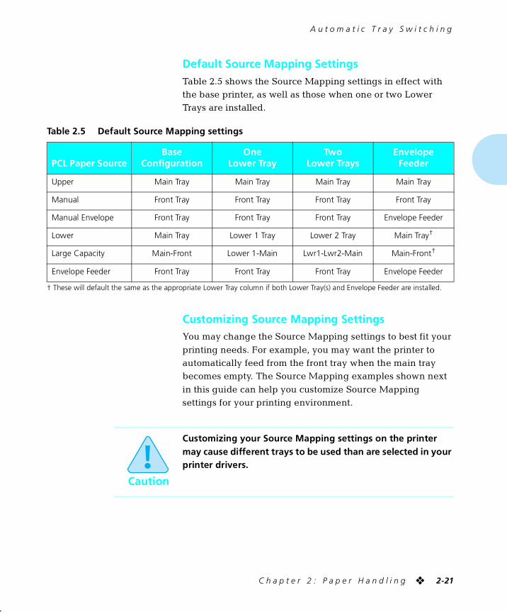
Default Source Mapping SettingsTable 2.5 shows the Source Mapping settings in effect with the base printer, as well as those when one or two Lower Trays are installed.
Customizing Source Mapping SettingsYou may change the Source Mapping settings to best fit your
printing needs. For example, you may want the printer to automatically feed from the front tray when the main tray becomes empty. The Source Mapping examples shown next
in this guide can help you customize Source Mapping settings for your printing environment.
† These will default the same as the appropriate Lower Tray column if both Lower Tray(s) and Envelope Feeder are installed.
Table 2.5 Default Source Mapping settings
PCL Paper SourceBase
ConfigurationOne
Lower TrayTwo
Lower TraysEnvelope
Feeder
Upper Main Tray Main Tray Main Tray Main Tray
Manual Front Tray Front Tray Front Tray Front Tray
Manual Envelope Front Tray Front Tray Front Tray Envelope Feeder
Lower Main Tray Lower 1 Tray Lower 2 Tray Main Tray†
Large Capacity Main-Front Lower 1-Main Lwr1-Lwr2-Main Main-Front†
Envelope Feeder Front Tray Front Tray Front Tray Envelope Feeder
Caution
Customizing your Source Mapping settings on the printer may cause different trays to be used than are selected in your printer drivers.
chapter2.frm Page 21 Friday, July 11, 1997 8:13 PM
A u t o m a t i c T r a y S w i t c h i n g
2-22 ❖ D o c u P r i n t 4 5 1 7 / 4 5 1 7 m p U s e r G u i d e
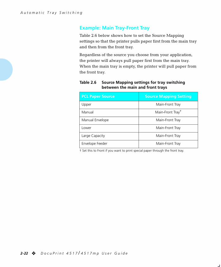
Example: Main Tray-Front TrayTable 2.6 below shows how to set the Source Mapping settings so that the printer pulls paper first from the main tray and then from the front tray.
Regardless of the source you choose from your application,
the printer will always pull paper first from the main tray. When the main tray is empty, the printer will pull paper from
the front tray.
† Set this to Front if you want to print special paper through the front tray.
Table 2.6 Source Mapping settings for tray switching between the main and front trays
PCL Paper Source Source Mapping Setting
Upper Main-Front Tray
Manual Main-Front Tray†
Manual Envelope Main-Front Tray
Lower Main-Front Tray
Large Capacity Main-Front Tray
Envelope Feeder Main-Front Tray
chapter2.frm Page 22 Friday, July 11, 1997 8:13 PM
A u t o m a t i c T r a y S w i t c h i n g
C h a p t e r 2 : P a p e r H a n d l i n g ❖ 2-23
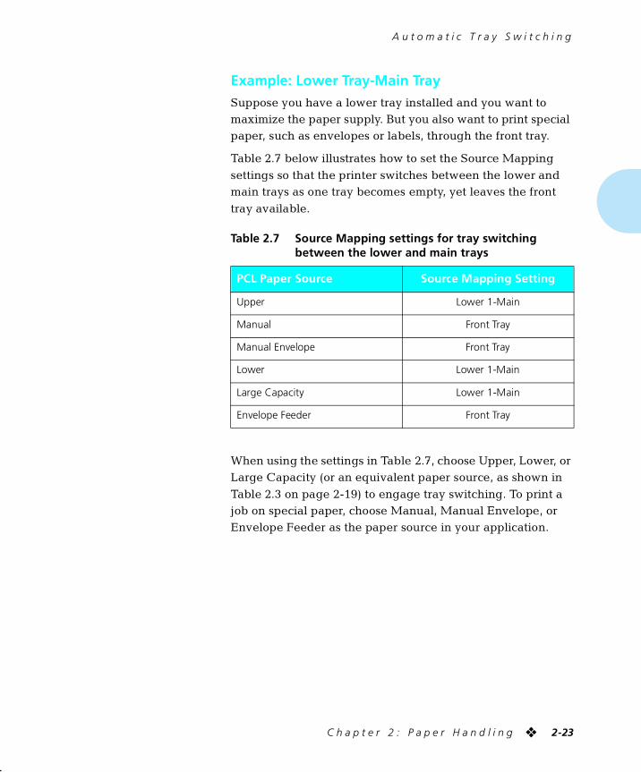
Example: Lower Tray-Main TraySuppose you have a lower tray installed and you want to maximize the paper supply. But you also want to print special paper, such as envelopes or labels, through the front tray.
Table 2.7 below illustrates how to set the Source Mapping
settings so that the printer switches between the lower and main trays as one tray becomes empty, yet leaves the front
tray available.
When using the settings in Table 2.7, choose Upper, Lower, or Large Capacity (or an equivalent paper source, as shown in
Table 2.3 on page 2-19) to engage tray switching. To print a job on special paper, choose Manual, Manual Envelope, or Envelope Feeder as the paper source in your application.
Table 2.7 Source Mapping settings for tray switching between the lower and main trays
PCL Paper Source Source Mapping Setting
Upper Lower 1-Main
Manual Front Tray
Manual Envelope Front Tray
Lower Lower 1-Main
Large Capacity Lower 1-Main
Envelope Feeder Front Tray
chapter2.frm Page 23 Friday, July 11, 1997 8:13 PM
P a p e r H a n d l i n g
2-24 ❖ D o c u P r i n t 4 5 1 7 / 4 5 1 7 m p U s e r G u i d e
Using theMailbox/Collator
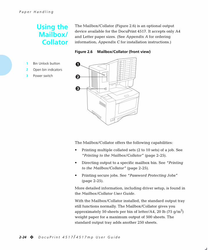
The Mailbox/Collator (Figure 2.6) is an optional output
device available for the DocuPrint 4517. It accepts only A4 and Letter paper sizes. (See Appendix A for ordering information; Appendix C for installation instructions.)
The Mailbox/Collator offers the following capabilities:
• Printing multiple collated sets (2 to 10 sets) of a job. See
“Printing to the Mailbox/Collator” (page 2-25).
• Directing output to a specific mailbox bin. See “Printing to the Mailbox/Collator” (page 2-25).
• Printing secure jobs. See “Password Protecting Jobs”
(page 2-25).
More detailed information, including driver setup, is found in the Mailbox/Collator User Guide.
With the Mailbox/Collator installed, the standard output tray
still functions normally. The Mailbox/Collator gives you approximately 50 sheets per bin of letter/A4, 20 lb (75 g/m2) weight paper for a maximum output of 500 sheets. The
standard output tray adds another 250 sheets.
Figure 2.6 Mailbox/Collator (front view)
1 Bin Unlock button
2 Open bin indicators
3 Power switch
chapter2.frm Page 24 Friday, July 11, 1997 8:13 PM
U s i n g t h e M a i l b o x / C o l l a t o r
C h a p t e r 2 : P a p e r H a n d l i n g ❖ 2-25
Printing to theMailbox/Collator
Using a DocuPrint 4517 printer driver, select a specific “Bin” or
“Collator” as the paper output destination for your job, then print your job.
• Bins are numbered from 1 - 10 (top to bottom).
• Each bin can hold up to 50 sheets of 20 lb (75 g/m2) paper. When a bin becomes full:
— The remainder of the print job is diverted to the top output tray when the Bin Full option (in the Mailbox
Menu) is set to Send to Standard, and the full bin is not password protected.
— Printing stops when the Bin Full option is set to Stop
Printing or if the full bin is password protected. Once you remove the output, the printer resumes printing.
PasswordProtecting Jobs
Using the DocuPrint 4517 Control Panel, you can set a different password for each mailbox bin and one password for the collator mode. A job sent to a password-enabled bin can only
be removed by the individual with the bin password; a job sent to the collator can only be removed from the password-enabled collator mode by the individual with the collator password.
Xerox recommends that you use the Mailbox/Collator exclusively in either collator mode or bin mode, not both, if you plan to set passwords. The only way to control the mode
in which it is used is through the use of passwords. If passwords are enabled for bins but disabled for collator, jobs sent to password-enabled bins can be removed by anyone
because no password is needed to open the collator. For this
Note
For job collation, select “Collator” from the DocuPrint 4517
printer driver, but do not select (disable) “Collate” in the application print window.
chapter2.frm Page 25 Friday, July 11, 1997 8:13 PM
U s i n g t h e M a i l b o x / C o l l a t o r
2-26 ❖ D o c u P r i n t 4 5 1 7 / 4 5 1 7 m p U s e r G u i d e
reason, Xerox recommends you either enable or disable
passwords for both bins and collator.
• If you plan to use passwords for bins, also set a password for collator mode. Distribute individual bin passwords to
the appropriate users. Do not distribute the password for collator mode.
• If you plan to use a password for collated jobs, also set
passwords for each bin. Distribute the collator password to the appropriate users. Do not distribute individual bin passwords.
See “Enabling Passwords” (below) and “Disabling
Passwords” (page 2-28) for instructions.
Enabling PasswordsFollow the instructions below to set passwords.
1 Power ON the printer.
The printer will complete its self-test and display the following message at the Control Panel Display:
OnlineReady
2 Press Online , then Menu and you will see:
Main MenuLanguage
3 Press Down until you see:
Main MenuMailbox Menu
4 Press Enter and the display changes to:
Mailbox MenuCollator
To set a collator password, continue to Step 5.
To set a bin password, skip to Step 6.
chapter2.frm Page 26 Friday, July 11, 1997 8:13 PM
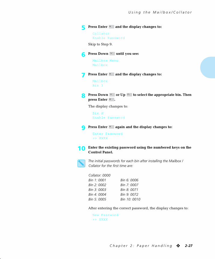
U s i n g t h e M a i l b o x / C o l l a t o r
C h a p t e r 2 : P a p e r H a n d l i n g ❖ 2-27
5 Press Enter and the display changes to:
CollatorEnable Password
Skip to Step 9.
6 Press Down until you see:
Mailbox MenuMailbox
7 Press Enter and the display changes to:
Mailbox Bin 1
8 Press Down or Up to select the appropriate bin. Then press Enter .
The display changes to:
Bin NEnable Password
9 Press Enter again and the display changes to:
Enter Password>> XXXX
10 Enter the existing password using the numbered keys on the Control Panel.
The initial passwords for each bin after installing the Mailbox / Collator for the first time are:
Collator: 0000Bin 1: 0001 Bin 6: 0006Bin 2: 0002 Bin 7: 0007Bin 3: 0003 Bin 8: 0071Bin 4: 0004 Bin 9: 0072Bin 5: 0005 Bin 10: 0010
After entering the correct password, the display changes to:
New Password>> XXXX
chapter2.frm Page 27 Friday, July 11, 1997 8:13 PM
U s i n g t h e M a i l b o x / C o l l a t o r
2-28 ❖ D o c u P r i n t 4 5 1 7 / 4 5 1 7 m p U s e r G u i d e
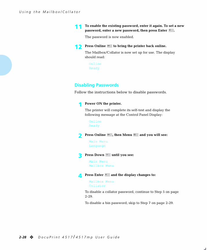
Disabling PasswordsFollow the instructions below to disable passwords.
11 To enable the existing password, enter it again. To set a new password, enter a new password, then press Enter .
The password is now enabled.
12 Press Online to bring the printer back online.
The Mailbox/Collator is now set up for use. The display should read:
OnlineReady
1 Power ON the printer.
The printer will complete its self-test and display the following message at the Control Panel Display:
OnlineReady
2 Press Online , then Menu and you will see:
Main MenuLanguage
3 Press Down until you see:
Main MenuMailbox Menu
4 Press Enter and the display changes to:
Mailbox MenuCollator
To disable a collator password, continue to Step 5 on page 2-29.
To disable a bin password, skip to Step 7 on page 2-29.
chapter2.frm Page 28 Friday, July 11, 1997 8:13 PM
U s i n g t h e M a i l b o x / C o l l a t o r
C h a p t e r 2 : P a p e r H a n d l i n g ❖ 2-29
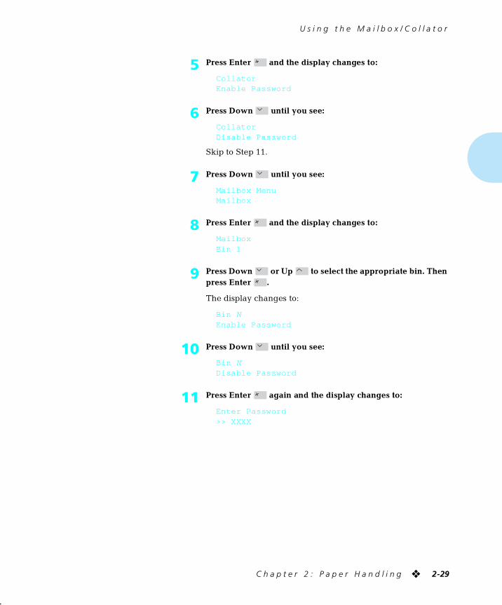
5 Press Enter and the display changes to:
CollatorEnable Password
6 Press Down until you see:
CollatorDisable Password
Skip to Step 11.
7 Press Down until you see:
Mailbox MenuMailbox
8 Press Enter and the display changes to:
Mailbox Bin 1
9 Press Down or Up to select the appropriate bin. Then press Enter .
The display changes to:
Bin NEnable Password
10 Press Down until you see:
Bin NDisable Password
11 Press Enter again and the display changes to:
Enter Password>> XXXX
chapter2.frm Page 29 Friday, July 11, 1997 8:13 PM
U s i n g t h e M a i l b o x / C o l l a t o r
2-30 ❖ D o c u P r i n t 4 5 1 7 / 4 5 1 7 m p U s e r G u i d e
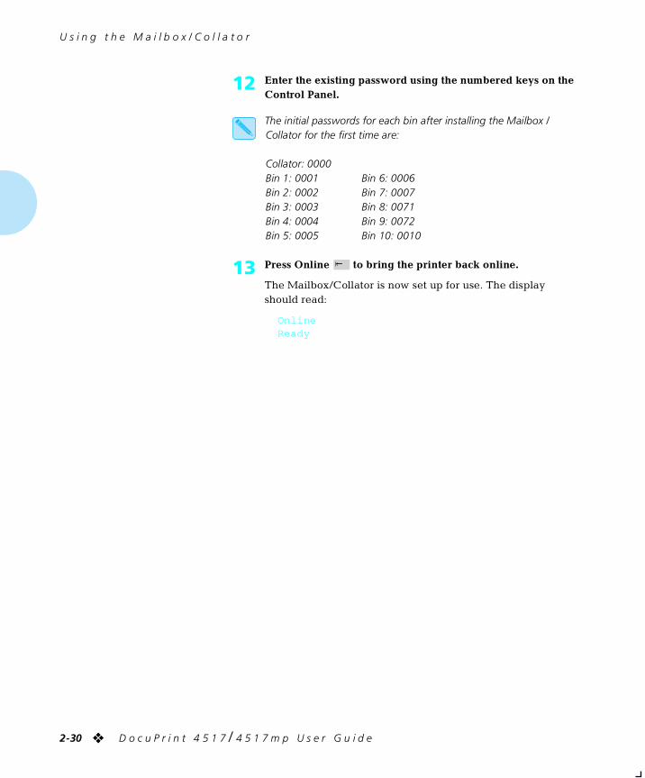
12 Enter the existing password using the numbered keys on the Control Panel.
The initial passwords for each bin after installing the Mailbox / Collator for the first time are:
Collator: 0000Bin 1: 0001 Bin 6: 0006Bin 2: 0002 Bin 7: 0007Bin 3: 0003 Bin 8: 0071Bin 4: 0004 Bin 9: 0072Bin 5: 0005 Bin 10: 0010
13 Press Online to bring the printer back online.
The Mailbox/Collator is now set up for use. The display should read:
OnlineReady
chapter2.frm Page 30 Friday, July 11, 1997 8:13 PM
U s i n g t h e M a i l b o x / C o l l a t o r
C h a p t e r 2 : P a p e r H a n d l i n g ❖ 2-31
Opening Bins Follow the appropriate instructions for opening either a
password-enabled or password-disabled bin.
Opening Password-Enabled Bins
To open a bin (or the collator) for which a password has been enabled:
1. Push the Bin Unlock button.
You are prompted to enter your password at the Control Panel.
2. Using the numbered Control Panel keys, enter your
password.
If you enter an invalid password, you will be prompted again to enter your password.
A light appears to indicate each unlocked bin. Open the
appropriate unlocked bins, then remove the output. You have approximately 30 seconds to open the bin(s).
Opening Password-Disabled Bins
Push the Bin Unlock button and a light appears to indicate each unlocked bin. Open all full bins, then remove the
printouts. You have approximately 30 seconds to open the bin(s). If the Mailbox/Collator re-locks, push the Bin Unlock button again immediately.
chapter2.frm Page 31 Friday, July 11, 1997 8:13 PM
P a p e r H a n d l i n g
2-32 ❖ D o c u P r i n t 4 5 1 7 / 4 5 1 7 m p U s e r G u i d e
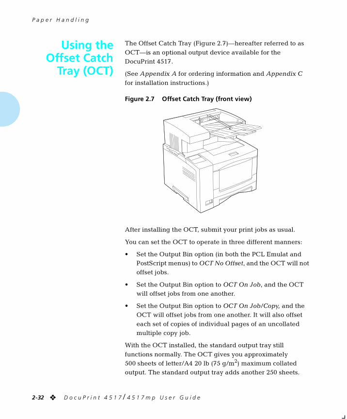
Using theOffset Catch
Tray (OCT)
The Offset Catch Tray (Figure 2.7)—hereafter referred to as
OCT—is an optional output device available for the DocuPrint 4517.
(See Appendix A for ordering information and Appendix C
for installation instructions.)
After installing the OCT, submit your print jobs as usual.
You can set the OCT to operate in three different manners:
• Set the Output Bin option (in both the PCL Emulat and PostScript menus) to OCT No Offset, and the OCT will not offset jobs.
• Set the Output Bin option to OCT On Job, and the OCT will offset jobs from one another.
• Set the Output Bin option to OCT On Job/Copy, and the OCT will offset jobs from one another. It will also offset
each set of copies of individual pages of an uncollated multiple copy job.
With the OCT installed, the standard output tray still
functions normally. The OCT gives you approximately 500 sheets of letter/A4 20 lb (75 g/m2) maximum collated output. The standard output tray adds another 250 sheets.
Figure 2.7 Offset Catch Tray (front view)
chapter2.frm Page 32 Friday, July 11, 1997 8:13 PM
P a p e r H a n d l i n g
C h a p t e r 2 : P a p e r H a n d l i n g ❖ 2-33
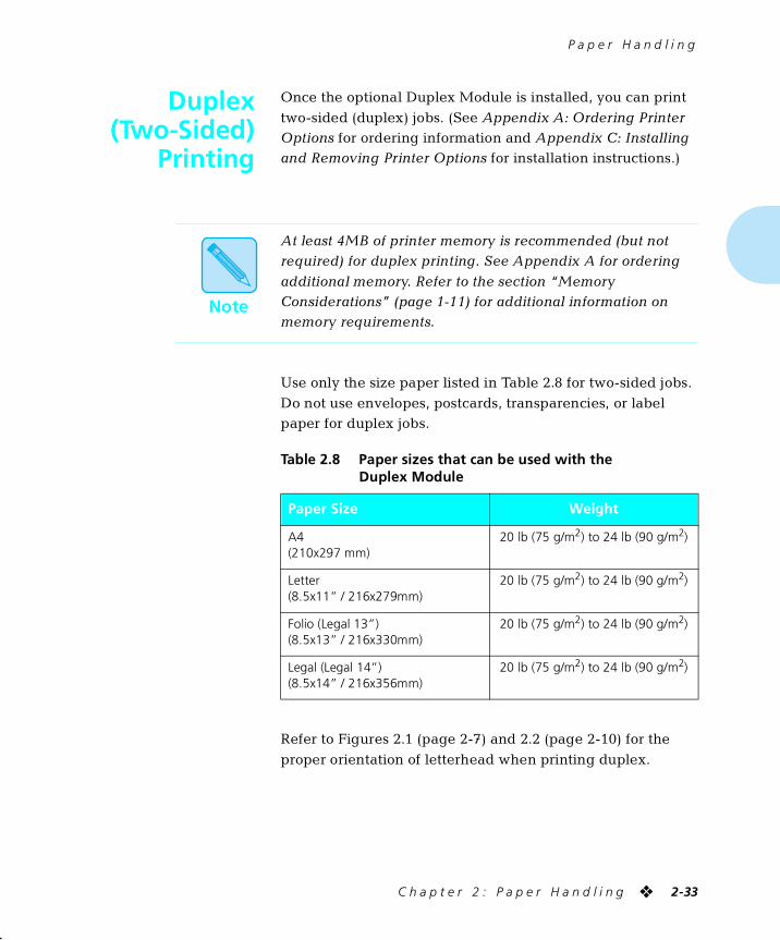
Duplex(Two-Sided)
Printing
Once the optional Duplex Module is installed, you can print
two-sided (duplex) jobs. (See Appendix A: Ordering Printer Options for ordering information and Appendix C: Installing and Removing Printer Options for installation instructions.)
Use only the size paper listed in Table 2.8 for two-sided jobs.
Do not use envelopes, postcards, transparencies, or label paper for duplex jobs.
Refer to Figures 2.1 (page 2-7) and 2.2 (page 2-10) for the
proper orientation of letterhead when printing duplex.
Note
At least 4MB of printer memory is recommended (but not required) for duplex printing. See Appendix A for ordering
additional memory. Refer to the section “Memory Considerations” (page 1-11) for additional information on memory requirements.
Table 2.8 Paper sizes that can be used with the Duplex Module
Paper Size Weight
A4(210x297 mm)
20 lb (75 g/m2) to 24 lb (90 g/m2)
Letter(8.5x11” / 216x279mm)
20 lb (75 g/m2) to 24 lb (90 g/m2)
Folio (Legal 13”)(8.5x13” / 216x330mm)
20 lb (75 g/m2) to 24 lb (90 g/m2)
Legal (Legal 14”)(8.5x14” / 216x356mm)
20 lb (75 g/m2) to 24 lb (90 g/m2)
chapter2.frm Page 33 Friday, July 11, 1997 8:13 PM
D u p l e x ( T w o - S i d e d ) P r i n t i n g
2-34 ❖ D o c u P r i n t 4 5 1 7 / 4 5 1 7 m p U s e r G u i d e
Print Orientationand Control Panel
Settings
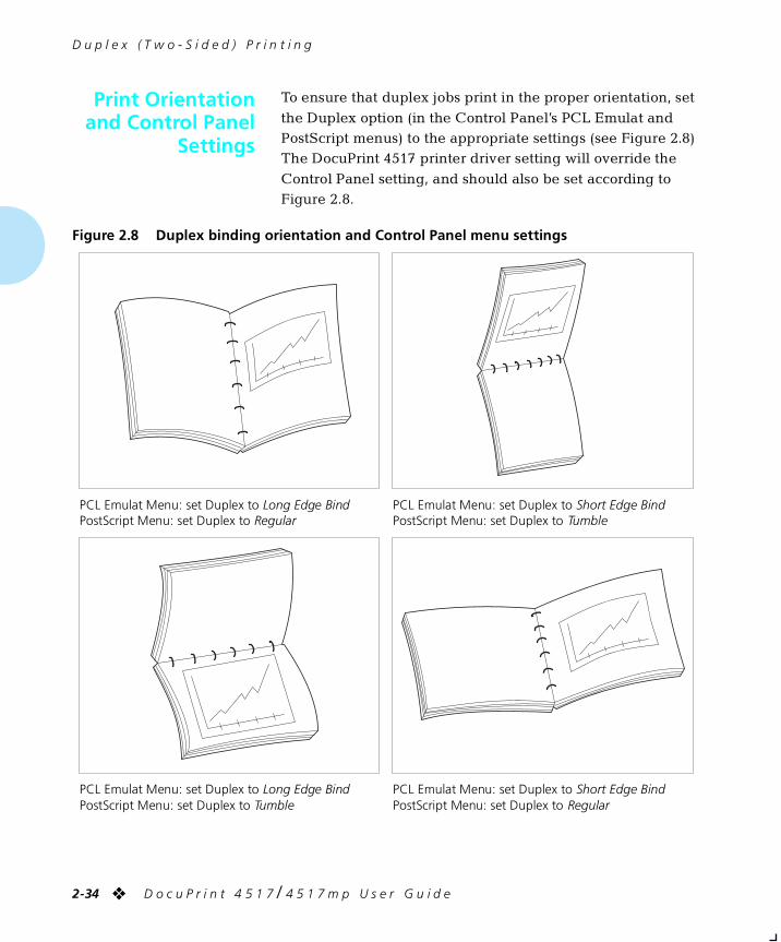
To ensure that duplex jobs print in the proper orientation, set
the Duplex option (in the Control Panel’s PCL Emulat and PostScript menus) to the appropriate settings (see Figure 2.8) The DocuPrint 4517 printer driver setting will override the
Control Panel setting, and should also be set according to Figure 2.8.
Figure 2.8 Duplex binding orientation and Control Panel menu settings
PCL Emulat Menu: set Duplex to Long Edge BindPostScript Menu: set Duplex to Regular
PCL Emulat Menu: set Duplex to Short Edge BindPostScript Menu: set Duplex to Tumble
PCL Emulat Menu: set Duplex to Long Edge BindPostScript Menu: set Duplex to Tumble
PCL Emulat Menu: set Duplex to Short Edge BindPostScript Menu: set Duplex to Regular
chapter2.frm Page 34 Friday, July 11, 1997 8:13 PM
Chapter 3
C h a p t e r 3 : U s i n g t h e C o n t r o l P a n e l ❖ 3-1
Using the Control Panel Chapter3
Control Panel Features ......................................................... 3-2The Display ........................................................................... 3-2
The Indicator Lights .............................................................. 3-3
The Keys .............................................................................. 3-4
Navigating the Menu System .............................................. 3-7Menu Indicators ................................................................... 3-9
Setting a Menu Option ....................................................... 3-10
Main Menu .......................................................................... 3-12Language Menu .................................................................. 3-13Mailbox Menu ..................................................................... 3-14PCL Emulat Menu ................................................................ 3-15PostScript Menu .................................................................. 3-20Interface Menu ................................................................... 3-24System Menu ...................................................................... 3-30Test Menu ........................................................................... 3-31Reset Menu ......................................................................... 3-32
chapter3.frm Page 1 Friday, July 11, 1997 8:15 PM
U s i n g t h e C o n t r o l P a n e l
3-2 ❖ D o c u P r i n t 4 5 1 7 / 4 5 1 7 m p U s e r G u i d e
Control PanelFeatures
The DocuPrint 4517 Control Panel (Figure 3.1) serves two
purposes:
1. It displays information about the status of the printer (or the job in process) and
2. It provides the means for changing printer settings to
control how the DocuPrint 4517 operates.
The Display The Control Panel’s display performs two functions.
• It informs you of printer status conditions, such as when
toner is low, when a paper tray is empty, when a job is in process, and so on.
For example, when you turn on the printer, you see the following message on the display:
Online
Ready
This message appears whenever the printer is online and ready to accept print jobs.
Figure 3.1 DocuPrint 4517 Control Panel1 2-line by 16-character display
2 Indicator lights
3 Control keys (8)
chapter3.frm Page 2 Friday, July 11, 1997 8:15 PM

C o n t r o l P a n e l F e a t u r e s
C h a p t e r 3 : U s i n g t h e C o n t r o l P a n e l ❖ 3-3
• It presents a hierarchy of menu options and settings to
configure and control the printer.
For example, when you press Menu after taking the printer offline, you see the following message on the
display:
Main Menu
Language >
Note that the > in this example is one of three indicators
you will see in the menu systems. See “Menu Indicators” (page 3-9) for more information on indicators.
See “Navigating the Menu System” (page 3-7) for
information on the menu system hierarchy.
The IndicatorLights
The Control Panel contains four indicator lights. Table 3.1
describes the function of each light.
Table 3.1 Control Panel indicator lights and their functions
Light Description
Online This is lit when the printer is online. It flashes for a few seconds while transitioning from printing to offline.
Form Feed This is lit as long as there is printable data in the printer, and is not extinguished until the “last” page is printed.
Fault This is lit when an error condition occurs that stops printing, and is not extinguished until all applicable error conditions are removed. Such error conditions include jams, out of paper, toner cartridge failures and other system errors.
Ready This is lit when the printer is ready to accept data and print it. It flashes when receiving data to print.
chapter3.frm Page 3 Friday, July 11, 1997 8:15 PM
C o n t r o l P a n e l F e a t u r e s
3-4 ❖ D o c u P r i n t 4 5 1 7 / 4 5 1 7 m p U s e r G u i d e
The Keys The Control Panel keypad consists of eight keys, identified
with international symbols and labeled in English.
The keys are also numbered 0 - 7. When you install the optional Mailbox / Collator, these same eight keys are used to
enter numeric passwords for each of the mailbox bins.
Table 3.2 describes the function of each key.
Table 3.2 Control Panel keys and their functions
Key Description
Online Toggles between online and offline.
When online, the printer is able to receive and print pages. When offline, page processing and printing halts, but the printer is still able to respond to status requests.
You must take the printer offline to:
• Access the menu system with Menu or Reset .
• Insert or remove a font card.
• Perform tasks such as forcing a form feed for a partially printed page.
The printer goes offline automatically when it has a fault condition such as a paper jam or an open cover. Use Online to put the printer back online after correcting such conditions.
Reset Displays the Reset Menu and the first reset function: Reset Printer.
Press Up or Down repeatedly to scroll through the other Reset Menu functions. See “Reset Menu” (page 3-32).
The printer must be offline for Reset to function.
Form Feed Prints a partial page of a PCL emulation job, if one exists in the printer (as indicated by the “Form Feed” indicator light).
The printer must be offline for Form Feed to function.
Menu Displays the Main Menu and its first submenu: Language.
The printer must be offline for Menu to function.
From any submenu, press Menu to go to the top of the Main Menu. See “Main Menu” (page 3-12) for a full description.
Table 3.2 Page 1 of 3
chapter3.frm Page 4 Friday, July 11, 1997 8:15 PM
C o n t r o l P a n e l F e a t u r e s
C h a p t e r 3 : U s i n g t h e C o n t r o l P a n e l ❖ 3-5
Esc In the menu system, exits the current menu level and returns to the previous one.
When setting network addresses, each segment of the address is set consecutively. Then the Esc key returns to the previous segment of the address rather than the previous menu.
Press Esc at any time in the menu system to go to the previous level. No changes to values will be saved unless you first press Enter .
Press Esc while at Reset Menu (or the top level of Main Menu) to exit either menu.
Enter When in the menu system, accesses, sets, or invokes the displayed submenu, value, or function.
• When a submenu is displayed, press Enter to access the submenu.
• When a printer setting is displayed, such as Copies, press Enter to set the current value as the default value.
• When setting a network address, press Enter to accept the current segment of the address, and advance to the next segment.
• When a printer action is displayed, such as any of the “Test Menu” (page 3-31) or “Reset Menu” (page 3-32) functions, press Enter to invoke the action.
When not in the menu system, acts as a Continue key.
• After certain error conditions when Auto Continue is Off, press Enter to continue the printing process. See Appendix D: Control Panel Options, for more information.
• In PCL emulation, press Enter to override a paper mismatch.
Table 3.2 Control Panel keys and their functions (continued)
Key Description
Table 3.2 Page 2 of 3
chapter3.frm Page 5 Friday, July 11, 1997 8:15 PM
C o n t r o l P a n e l F e a t u r e s
3-6 ❖ D o c u P r i n t 4 5 1 7 / 4 5 1 7 m p U s e r G u i d e
Up In the menu system, scrolls backward (up) through submenus or through the current list of values or functions.
For numeric values such as number of Copies, press Up to increase the number.
Scrolling wraps—if the first item in a list is displayed, press Up to display the last item in the list.
Press Up for more than two seconds to scroll continuously.
When the hard disk option has been installed, press Up to respond to a disk failure error message. Pressing Up will reformat the hard disk. See Chapter 6: Troubleshooting for more information on hard disk failure error messages.
Down In the menu system, scrolls forward (down) through the submenus or through the current list of values or actions.
For numeric values such as number of Copies, press Down to decrease the number.
Scrolling wraps—if the last item in a list is displayed, press Down to display the first item in the list.
Press Down for more than two seconds to scroll continuously.
When the hard disk option has been installed, press Down to respond to a disk failure error message. Hard disk usage will be aborted when Down is pressed. See Chapter 6: Troubleshooting for more information on hard disk failure error messages.
Table 3.2 Control Panel keys and their functions (continued)
Key Description
Table 3.2 Page 3 of 3
chapter3.frm Page 6 Friday, July 11, 1997 8:15 PM
U s i n g t h e C o n t r o l P a n e l
C h a p t e r 3 : U s i n g t h e C o n t r o l P a n e l ❖ 3-7
Navigating theMenu System
The DocuPrint 4517 Control Panel contains two menu
structures.
• Main Menu and its submenus:
— Language
— Mailbox Menu
(This menu appears only when the Mailbox / Collator option is installed.)
— PCL Emulat Menu
— PostScript Menu
(This menu appears only when the PostScript option is installed.)
— Interface Menu
— System Menu
— Test Menu
Press Online then Menu to access the Main Menu. Each of the submenus may have other submenus, settings, or functions. See “Main Menu” (page 3-12) for
more information.
chapter3.frm Page 7 Friday, July 11, 1997 8:15 PM
N a v i g a t i n g t h e M e n u S y s t e m
3-8 ❖ D o c u P r i n t 4 5 1 7 / 4 5 1 7 m p U s e r G u i d e
• Reset Menu and its functions:
— Reset Printer
— Reset Menus
— Reset Ethernet(This function appears only when the optional
Ethernet card is installed.)
— Reset Token Ring(This function appears only when the optional Token
Ring card is installed.)
— Reset LocalTalk(This function appears only when the optional LocalTalk card is installed.)
— Reset All
— Cancel PS Job (This function appears only when the PostScript option is installed and a PostScript job is sent.)
Press Online then Reset to access the Reset Menu. See “Reset Menu” (page 3-32).
chapter3.frm Page 8 Friday, July 11, 1997 8:15 PM
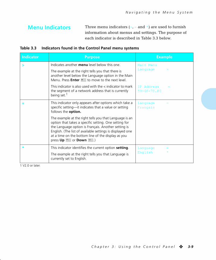
N a v i g a t i n g t h e M e n u S y s t e m
C h a p t e r 3 : U s i n g t h e C o n t r o l P a n e l ❖ 3-9
Menu Indicators Three menu indicators (>, = and * ) are used to furnish
information about menus and settings. The purpose of each indicator is described in Table 3.3 below.
1 V2.0 or later.
Table 3.3 Indicators found in the Control Panel menu systems
Indicator Purpose Example
> Indicates another menu level below this one.
The example at the right tells you that there is another level below the Language option in the Main Menu. Press Enter to move to the next level.
This indicator is also used with the < indicator to mark the segment of a network address that is currently being set.1
Main MenuLanguage >
IP Address =50>60<70.80
= This indicator only appears after options which take a specific setting—it indicates that a value or setting follows the option.
The example at the right tells you that Language is an option that takes a specific setting. One setting for the Language option is Français. Another setting is English. (The list of available settings is displayed one at a time on the bottom line of the display as you press Up or Down .)
Language =Français
* This indicator identifies the current option setting.
The example at the right tells you that Language is currently set to English.
Language =English *
chapter3.frm Page 9 Friday, July 11, 1997 8:15 PM
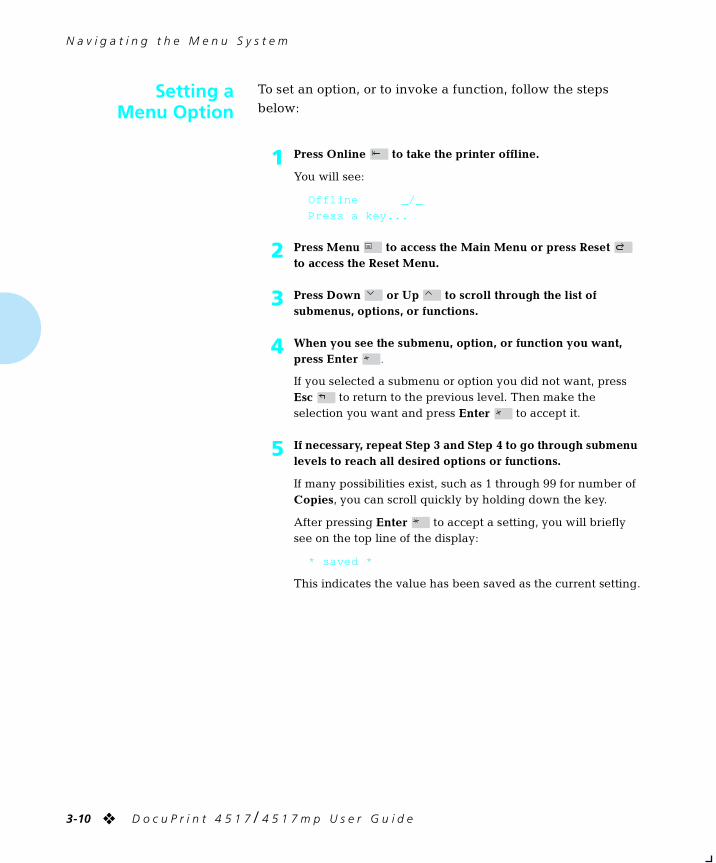
N a v i g a t i n g t h e M e n u S y s t e m
3-10 ❖ D o c u P r i n t 4 5 1 7 / 4 5 1 7 m p U s e r G u i d e
Setting aMenu Option
To set an option, or to invoke a function, follow the steps
below:
1 Press Online to take the printer offline.
You will see:
Offline _/_
Press a key...
2 Press Menu to access the Main Menu or press Reset to access the Reset Menu.
3 Press Down or Up to scroll through the list of submenus, options, or functions.
4 When you see the submenu, option, or function you want, press Enter .
If you selected a submenu or option you did not want, press Esc to return to the previous level. Then make the selection you want and press Enter to accept it.
5 If necessary, repeat Step 3 and Step 4 to go through submenu levels to reach all desired options or functions.
If many possibilities exist, such as 1 through 99 for number of Copies, you can scroll quickly by holding down the key.
After pressing Enter to accept a setting, you will briefly see on the top line of the display:
* saved *
This indicates the value has been saved as the current setting.
chapter3.frm Page 10 Friday, July 11, 1997 8:15 PM
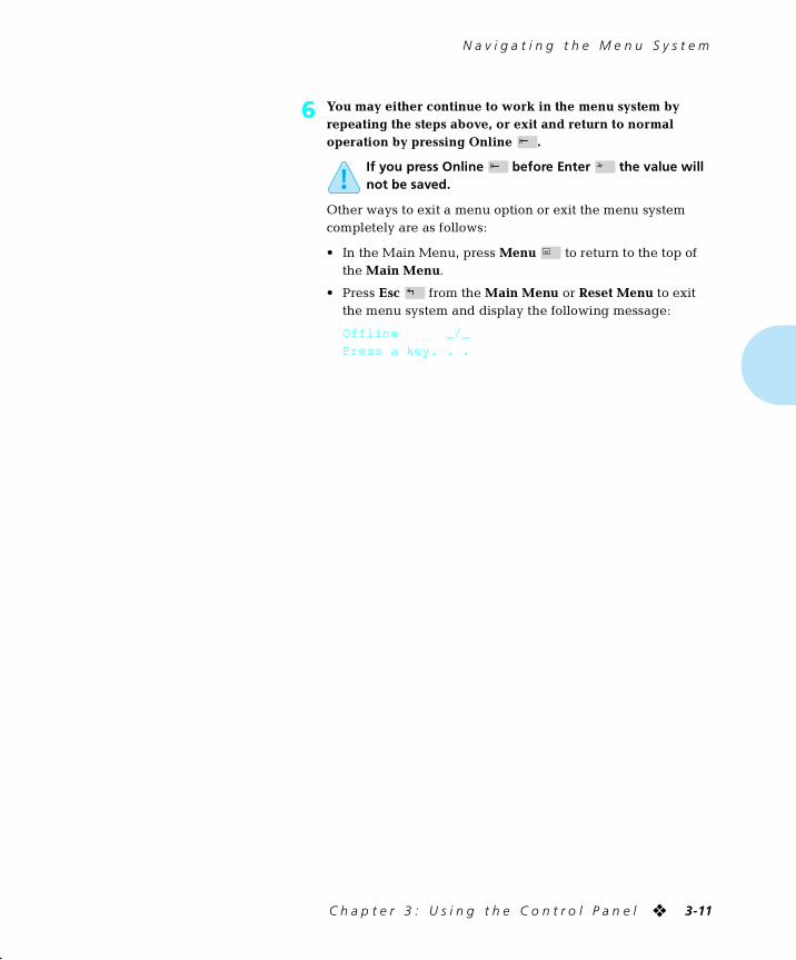
N a v i g a t i n g t h e M e n u S y s t e m
C h a p t e r 3 : U s i n g t h e C o n t r o l P a n e l ❖ 3-11
6 You may either continue to work in the menu system by repeating the steps above, or exit and return to normal operation by pressing Online .
If you press Online before Enter the value will not be saved.
Other ways to exit a menu option or exit the menu system completely are as follows:
• In the Main Menu, press Menu to return to the top of the Main Menu.
• Press Esc from the Main Menu or Reset Menu to exit the menu system and display the following message:
Offline _/_
Press a key. . .
chapter3.frm Page 11 Friday, July 11, 1997 8:15 PM
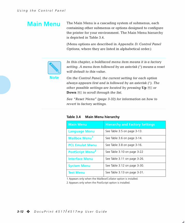
U s i n g t h e C o n t r o l P a n e l
3-12 ❖ D o c u P r i n t 4 5 1 7 / 4 5 1 7 m p U s e r G u i d e
Main Menu The Main Menu is a cascading system of submenus, each
containing other submenus or options designed to configure the printer for your environment. The Main Menu hierarchy is depicted in Table 3.4.
(Menu options are described in Appendix D: Control Panel Options, where they are listed in alphabetical order.)
1 Appears only when the Mailbox/Collator option is installed.
2 Appears only when the PostScript option is installed.
Note
In this chapter, a boldfaced menu item means it is a factory
setting. A menu item followed by an asterisk (*) means a reset will default to this value.
On the Control Panel, the current setting for each option
always appears first and is followed by an asterisk (*). The other possible settings are located by pressing Up or Down to scroll through the list.
See “Reset Menu” (page 3-32) for information on how to
revert to factory settings.
Table 3.4 Main Menu hierarchy
Main Menu Hierarchy and Factory Settings
Language Menu See Table 3.5 on page 3-13.
Mailbox Menu1 See Table 3.6 on page 3-14.
PCL Emulat Menu See Table 3.8 on page 3-16.
PostScript Menu2 See Table 3.10 on page 3-22
Interface Menu See Table 3.11 on page 3-26.
System Menu See Table 3.12 on page 3-30.
Test Menu See Table 3.13 on page 3-31.
chapter3.frm Page 12 Friday, July 11, 1997 8:15 PM
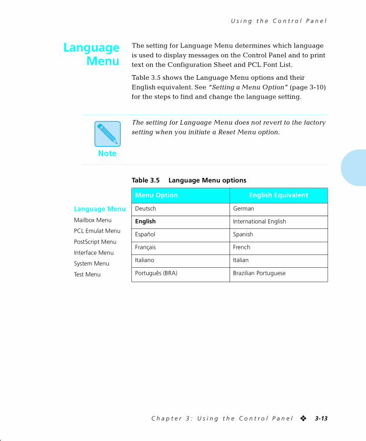
U s i n g t h e C o n t r o l P a n e l
C h a p t e r 3 : U s i n g t h e C o n t r o l P a n e l ❖ 3-13
LanguageMenu
The setting for Language Menu determines which language
is used to display messages on the Control Panel and to print text on the Configuration Sheet and PCL Font List.
Table 3.5 shows the Language Menu options and their
English equivalent. See “Setting a Menu Option” (page 3-10) for the steps to find and change the language setting.
Note
The setting for Language Menu does not revert to the factory
setting when you initiate a Reset Menu option.
Table 3.5 Language Menu options
Main Menu Menu Option English Equivalent
Language Menu
Mailbox Menu
PCL Emulat Menu
PostScript Menu
Interface Menu
System Menu
Test Menu
Deutsch German
English International English
Español Spanish
Français French
Italiano Italian
Português (BRA) Brazilian Portuguese
chapter3.frm Page 13 Friday, July 11, 1997 8:15 PM
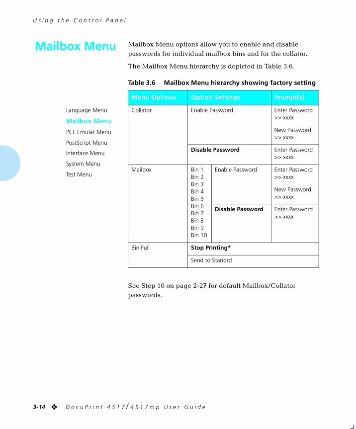
U s i n g t h e C o n t r o l P a n e l
3-14 ❖ D o c u P r i n t 4 5 1 7 / 4 5 1 7 m p U s e r G u i d e
Mailbox Menu Mailbox Menu options allow you to enable and disable
passwords for individual mailbox bins and for the collator.
The Mailbox Menu hierarchy is depicted in Table 3.6.
See Step 10 on page 2-27 for default Mailbox/Collator
passwords.
Table 3.6 Mailbox Menu hierarchy showing factory setting
Menu Options Option Settings Prompt(s)
Language Menu
Mailbox Menu
PCL Emulat Menu
PostScript Menu
Interface Menu
System Menu
Test Menu
Collator Enable Password Enter Password>> xxxx
New Password>> xxxx
Disable Password Enter Password>> xxxx
Mailbox Bin 1Bin 2Bin 3Bin 4Bin 5Bin 6Bin 7Bin 8Bin 9Bin 10
Enable Password Enter Password>> xxxx
New Password>> xxxx
Disable Password Enter Password>> xxxx
Bin Full Stop Printing*
Send to Standrd
chapter3.frm Page 14 Friday, July 11, 1997 8:15 PM
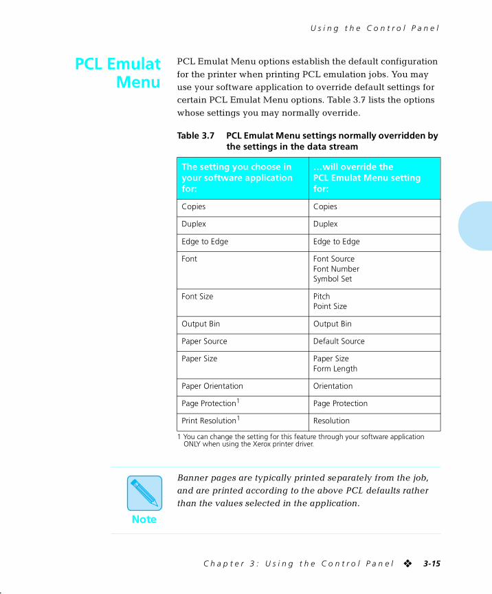
U s i n g t h e C o n t r o l P a n e l
C h a p t e r 3 : U s i n g t h e C o n t r o l P a n e l ❖ 3-15
PCL EmulatMenu
PCL Emulat Menu options establish the default configuration
for the printer when printing PCL emulation jobs. You may use your software application to override default settings for certain PCL Emulat Menu options. Table 3.7 lists the options
whose settings you may normally override.
1 You can change the setting for this feature through your software application ONLY when using the Xerox printer driver.
Table 3.7 PCL Emulat Menu settings normally overridden by the settings in the data stream
The setting you choose in your software application for:
…will override the PCL Emulat Menu setting for:
Copies Copies
Duplex Duplex
Edge to Edge Edge to Edge
Font Font SourceFont NumberSymbol Set
Font Size PitchPoint Size
Output Bin Output Bin
Paper Source Default Source
Paper Size Paper SizeForm Length
Paper Orientation Orientation
Page Protection1 Page Protection
Print Resolution1 Resolution
Note
Banner pages are typically printed separately from the job, and are printed according to the above PCL defaults rather than the values selected in the application.
chapter3.frm Page 15 Friday, July 11, 1997 8:15 PM
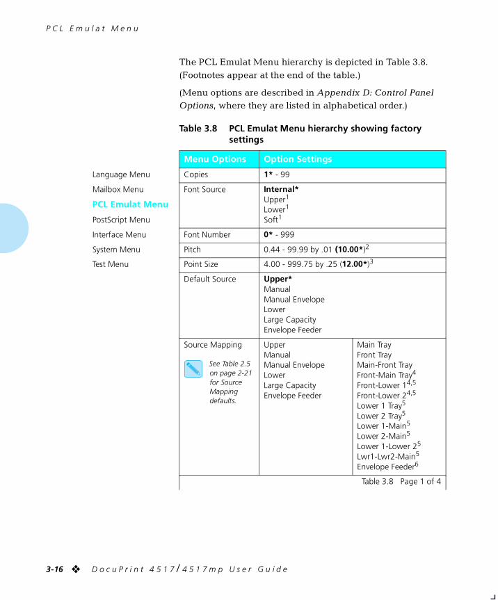
P C L E m u l a t M e n u
3-16 ❖ D o c u P r i n t 4 5 1 7 / 4 5 1 7 m p U s e r G u i d e
The PCL Emulat Menu hierarchy is depicted in Table 3.8.
(Footnotes appear at the end of the table.)
(Menu options are described in Appendix D: Control Panel Options, where they are listed in alphabetical order.)
Table 3.8 PCL Emulat Menu hierarchy showing factory settings
Menu Options Option Settings
Language Menu
Mailbox Menu
PCL Emulat Menu
PostScript Menu
Interface Menu
System Menu
Test Menu
Copies 1* - 99
Font Source Internal*Upper1
Lower1
Soft1
Font Number 0* - 999
Pitch 0.44 - 99.99 by .01 (10.00*)2
Point Size 4.00 - 999.75 by .25 (12.00*)3
Default Source Upper*ManualManual EnvelopeLowerLarge CapacityEnvelope Feeder
Source Mapping
See Table 2.5 on page 2-21 for Source Mapping defaults.
UpperManualManual EnvelopeLowerLarge CapacityEnvelope Feeder
Main TrayFront TrayMain-Front TrayFront-Main Tray4
Front-Lower 14,5
Front-Lower 24,5
Lower 1 Tray5
Lower 2 Tray5
Lower 1-Main5
Lower 2-Main5
Lower 1-Lower 25
Lwr1-Lwr2-Main5
Envelope Feeder6
Table 3.8 Page 1 of 4
chapter3.frm Page 16 Friday, July 11, 1997 8:15 PM
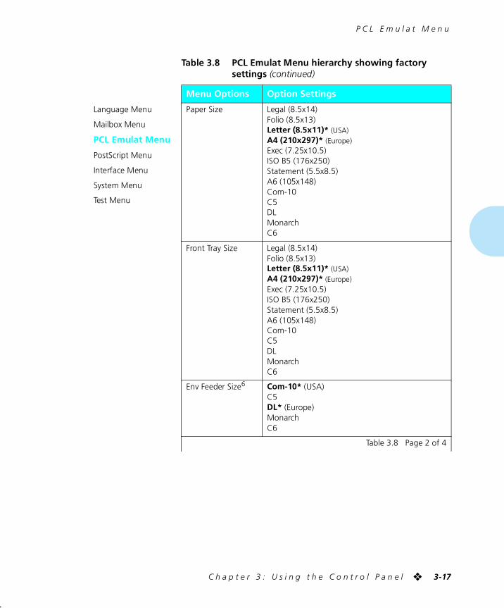
P C L E m u l a t M e n u
C h a p t e r 3 : U s i n g t h e C o n t r o l P a n e l ❖ 3-17
Language Menu
Mailbox Menu
PCL Emulat Menu
PostScript Menu
Interface Menu
System Menu
Test Menu
Paper Size Legal (8.5x14)Folio (8.5x13)Letter (8.5x11)* (USA)A4 (210x297)* (Europe)Exec (7.25x10.5)ISO B5 (176x250)Statement (5.5x8.5)A6 (105x148)Com-10C5DLMonarchC6
Front Tray Size Legal (8.5x14)Folio (8.5x13)Letter (8.5x11)* (USA)A4 (210x297)* (Europe)Exec (7.25x10.5)ISO B5 (176x250)Statement (5.5x8.5)A6 (105x148)Com-10C5DLMonarchC6
Env Feeder Size6 Com-10* (USA)C5DL* (Europe)MonarchC6
Table 3.8 PCL Emulat Menu hierarchy showing factory settings (continued)
Menu Options Option Settings
Table 3.8 Page 2 of 4
chapter3.frm Page 17 Friday, July 11, 1997 8:15 PM
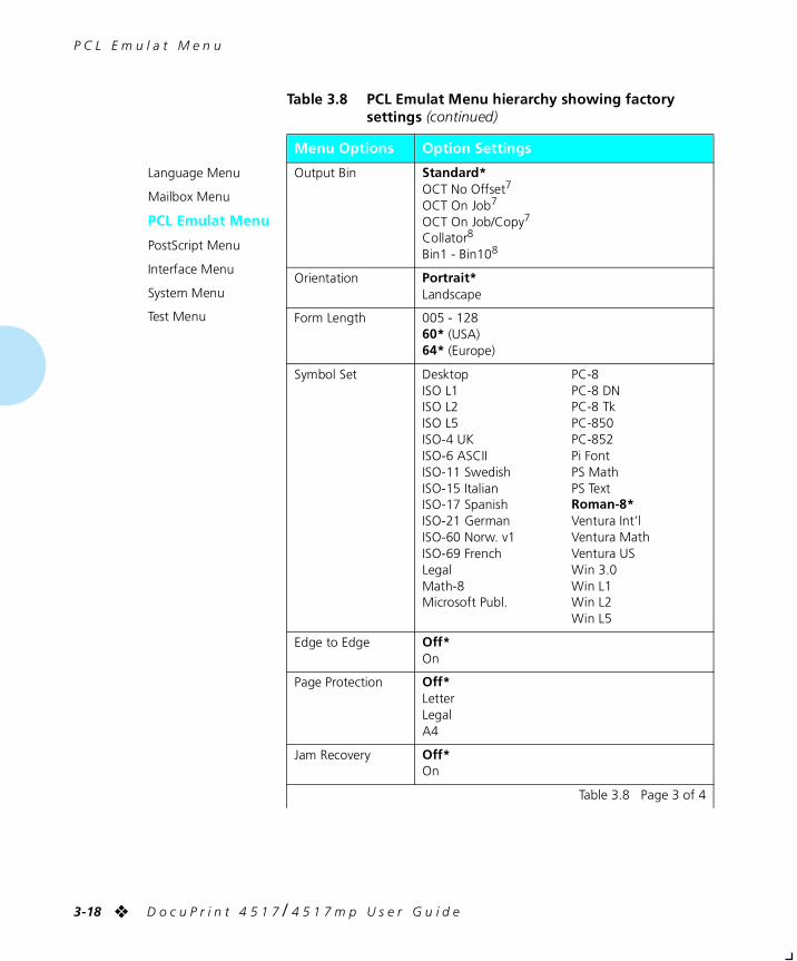
P C L E m u l a t M e n u
3-18 ❖ D o c u P r i n t 4 5 1 7 / 4 5 1 7 m p U s e r G u i d e
Language Menu
Mailbox Menu
PCL Emulat Menu
PostScript Menu
Interface Menu
System Menu
Test Menu
Output Bin Standard*OCT No Offset7
OCT On Job7
OCT On Job/Copy7
Collator8
Bin1 - Bin108
Orientation Portrait*Landscape
Form Length 005 - 12860* (USA)64* (Europe)
Symbol Set DesktopISO L1ISO L2ISO L5ISO-4 UKISO-6 ASCIIISO-11 SwedishISO-15 ItalianISO-17 SpanishISO-21 GermanISO-60 Norw. v1ISO-69 FrenchLegalMath-8Microsoft Publ.
PC-8PC-8 DNPC-8 TkPC-850PC-852Pi FontPS MathPS TextRoman-8*Ventura Int’lVentura MathVentura USWin 3.0Win L1Win L2Win L5
Edge to Edge Off*On
Page Protection Off*LetterLegalA4
Jam Recovery Off*On
Table 3.8 PCL Emulat Menu hierarchy showing factory settings (continued)
Menu Options Option Settings
Table 3.8 Page 3 of 4
chapter3.frm Page 18 Friday, July 11, 1997 8:15 PM
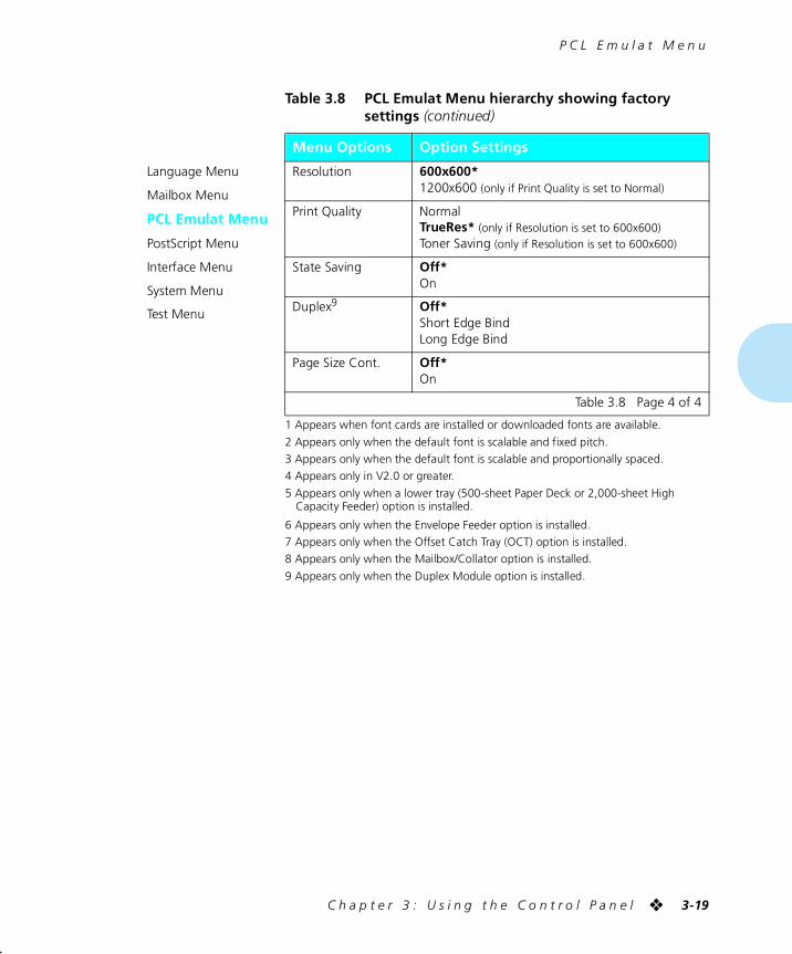
P C L E m u l a t M e n u
C h a p t e r 3 : U s i n g t h e C o n t r o l P a n e l ❖ 3-19
1 Appears when font cards are installed or downloaded fonts are available.
2 Appears only when the default font is scalable and fixed pitch.
3 Appears only when the default font is scalable and proportionally spaced.
4 Appears only in V2.0 or greater.
5 Appears only when a lower tray (500-sheet Paper Deck or 2,000-sheet High Capacity Feeder) option is installed.
6 Appears only when the Envelope Feeder option is installed.
7 Appears only when the Offset Catch Tray (OCT) option is installed.
8 Appears only when the Mailbox/Collator option is installed.
9 Appears only when the Duplex Module option is installed.
Language Menu
Mailbox Menu
PCL Emulat Menu
PostScript Menu
Interface Menu
System Menu
Test Menu
Resolution 600x600*1200x600 (only if Print Quality is set to Normal)
Print Quality NormalTrueRes* (only if Resolution is set to 600x600)Toner Saving (only if Resolution is set to 600x600)
State Saving Off*On
Duplex9 Off*Short Edge BindLong Edge Bind
Page Size Cont. Off*On
Table 3.8 PCL Emulat Menu hierarchy showing factory settings (continued)
Menu Options Option Settings
Table 3.8 Page 4 of 4
chapter3.frm Page 19 Friday, July 11, 1997 8:15 PM
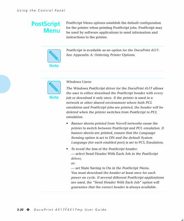
U s i n g t h e C o n t r o l P a n e l
3-20 ❖ D o c u P r i n t 4 5 1 7 / 4 5 1 7 m p U s e r G u i d e
PostScriptMenu
PostScript Menu options establish the default configuration
for the printer when printing PostScript jobs. PostScript may be used by software applications to send information and instructions to the printer.
Note
PostScript is available as an option for the DocuPrint 4517. See Appendix A: Ordering Printer Options.
Note
Windows Users:
The Windows PostScript driver for the DocuPrint 4517 allows the user to either download the PostScript header with every job or download it only once. If the printer is used in a
network or other shared environment where both PCL emulation and PostScript jobs are printed, the header will be deleted when the printer switches from PostScript to PCL
emulation.
• Banner sheets printed from Novell networks cause the printer to switch between PostScript and PCL emulation. If banner sheets are printed, ensure that the Language
Sensing option is set to ON and the default System Language (for each enabled port) is set to PCL Emulation.
• To avoid the loss of the PostScript header:
— select Send Header With Each Job in the PostScript driver, or:
— set State Saving to On in the PostScript Menu. You must download the header at least once for each power on cycle. If several different PostScript applications
are used, the “Send Header With Each Job” option will guarantee that the correct header is always available.
chapter3.frm Page 20 Friday, July 11, 1997 8:15 PM
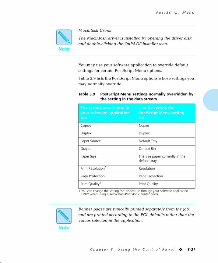
P o s t S c r i p t M e n u
C h a p t e r 3 : U s i n g t h e C o n t r o l P a n e l ❖ 3-21
You may use your software application to override default settings for certain PostScript Menu options.
Table 3.9 lists the PostScript Menu options whose settings you may normally override.
1 You can change the setting for this feature through your software application ONLY when using a Xerox DocuPrint 4517 printer driver.
Note
Macintosh Users:
The Macintosh driver is installed by opening the driver disk and double-clicking the OnPAGE installer icon.
Table 3.9 PostScript Menu settings normally overridden by the setting in the data stream
The setting you choose in your software application for:
…will override the PostScript Menu settingfor:
Copies Copies
Duplex Duplex
Paper Source Default Tray
Output Output Bin
Paper Size The size paper currently in the default tray
Print Resolution1 Resolution
Page Protection Page Protection
Print Quality1 Print Quality
Note
Banner pages are typically printed separately from the job, and are printed according to the PCL defaults rather than the values selected in the application.
chapter3.frm Page 21 Friday, July 11, 1997 8:15 PM
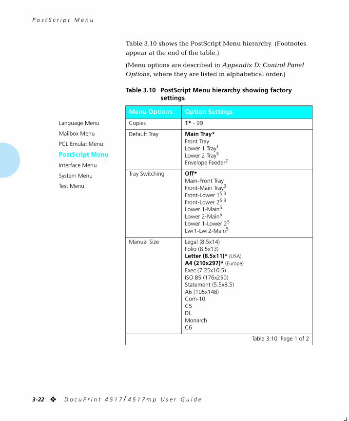
P o s t S c r i p t M e n u
3-22 ❖ D o c u P r i n t 4 5 1 7 / 4 5 1 7 m p U s e r G u i d e
Table 3.10 shows the PostScript Menu hierarchy. (Footnotes
appear at the end of the table.)
(Menu options are described in Appendix D: Control Panel Options, where they are listed in alphabetical order.)
Table 3.10 PostScript Menu hierarchy showing factory settings
Menu Options Option Settings
Language Menu
Mailbox Menu
PCL Emulat Menu
PostScript Menu
Interface Menu
System Menu
Test Menu
Copies 1* - 99
Default Tray Main Tray*Front TrayLower 1 Tray1
Lower 2 Tray5
Envelope Feeder2
Tray Switching Off*Main-Front TrayFront-Main Tray3
Front-Lower 15,3
Front-Lower 25,3
Lower 1-Main5
Lower 2-Main5
Lower 1-Lower 25
Lwr1-Lwr2-Main5
Manual Size Legal (8.5x14)Folio (8.5x13)Letter (8.5x11)* (USA)A4 (210x297)* (Europe)Exec (7.25x10.5)ISO B5 (176x250)Statement (5.5x8.5)A6 (105x148)Com-10C5DLMonarchC6
Table 3.10 Page 1 of 2
chapter3.frm Page 22 Friday, July 11, 1997 8:15 PM
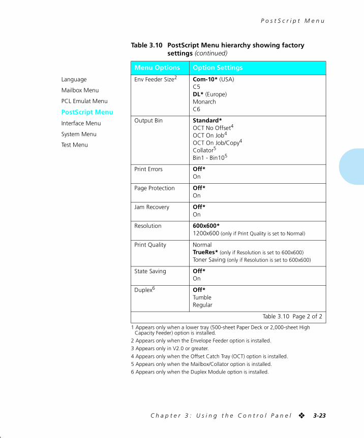
P o s t S c r i p t M e n u
C h a p t e r 3 : U s i n g t h e C o n t r o l P a n e l ❖ 3-23
1 Appears only when a lower tray (500-sheet Paper Deck or 2,000-sheet High Capacity Feeder) option is installed.
2 Appears only when the Envelope Feeder option is installed.
3 Appears only in V2.0 or greater.
4 Appears only when the Offset Catch Tray (OCT) option is installed.
5 Appears only when the Mailbox/Collator option is installed.
6 Appears only when the Duplex Module option is installed.
Language
Mailbox Menu
PCL Emulat Menu
PostScript Menu
Interface Menu
System Menu
Test Menu
Env Feeder Size2 Com-10* (USA)C5DL* (Europe)MonarchC6
Output Bin Standard*OCT No Offset4
OCT On Job4
OCT On Job/Copy4
Collator5
Bin1 - Bin105
Print Errors Off*On
Page Protection Off*On
Jam Recovery Off*On
Resolution 600x600*1200x600 (only if Print Quality is set to Normal)
Print Quality NormalTrueRes* (only if Resolution is set to 600x600)Toner Saving (only if Resolution is set to 600x600)
State Saving Off*On
Duplex6 Off*TumbleRegular
Table 3.10 PostScript Menu hierarchy showing factory settings (continued)
Menu Options Option Settings
Table 3.10 Page 2 of 2
chapter3.frm Page 23 Friday, July 11, 1997 8:15 PM
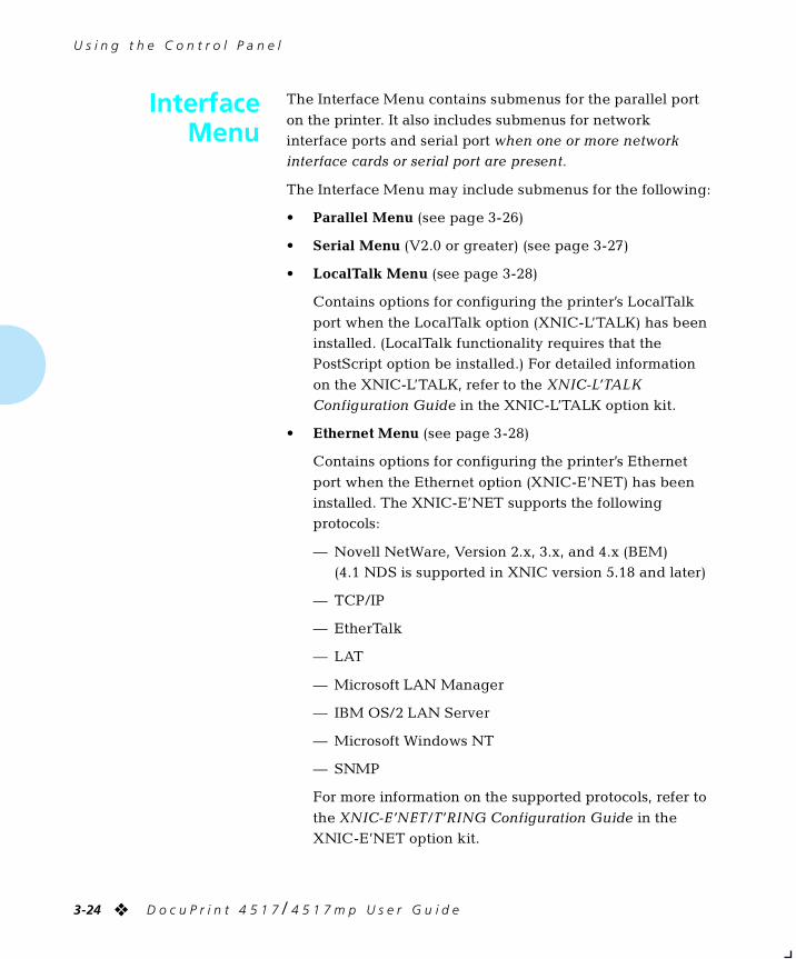
U s i n g t h e C o n t r o l P a n e l
3-24 ❖ D o c u P r i n t 4 5 1 7 / 4 5 1 7 m p U s e r G u i d e
InterfaceMenu
The Interface Menu contains submenus for the parallel port
on the printer. It also includes submenus for network interface ports and serial port when one or more network interface cards or serial port are present.
The Interface Menu may include submenus for the following:
• Parallel Menu (see page 3-26)
• Serial Menu (V2.0 or greater) (see page 3-27)
• LocalTalk Menu (see page 3-28)
Contains options for configuring the printer’s LocalTalk
port when the LocalTalk option (XNIC-L’TALK) has been installed. (LocalTalk functionality requires that the PostScript option be installed.) For detailed information
on the XNIC-L’TALK, refer to the XNIC-L’TALK Configuration Guide in the XNIC-L’TALK option kit.
• Ethernet Menu (see page 3-28)
Contains options for configuring the printer’s Ethernet
port when the Ethernet option (XNIC-E’NET) has been installed. The XNIC-E’NET supports the following protocols:
— Novell NetWare, Version 2.x, 3.x, and 4.x (BEM)(4.1 NDS is supported in XNIC version 5.18 and later)
— TCP/IP
— EtherTalk
— LAT
— Microsoft LAN Manager
— IBM OS/2 LAN Server
— Microsoft Windows NT
— SNMP
For more information on the supported protocols, refer to
the XNIC-E’NET/T’RING Configuration Guide in the XNIC-E’NET option kit.
chapter3.frm Page 24 Friday, July 11, 1997 8:15 PM
I n t e r f a c e M e n u
C h a p t e r 3 : U s i n g t h e C o n t r o l P a n e l ❖ 3-25
• Token Ring Menu (see page 3-29)
Contains options for configuring the printer’s Token Ring port, when the Token Ring option (XNIC-T’RING) has been installed. The XNIC-T’RING supports the following
protocols:
— Novell NetWare, Version 2.x, 3.x, and 4.x (BEM)(4.1 NDS is supported in XNIC version 5.18 and later)
— TCP/IP
— TokenTalk
— Microsoft LAN Manager
— IBM OS/2 LAN Server
— Microsoft Windows NT
— SNMP
For more information on the supported protocols, refer to
the XNIC-E’NET/T’RING Configuration Guide in the XNIC-T’RING option kit.
Table 3.11, starting on page 3-26, shows the Interface Menu
hierarchy. (Footnotes appear at the end of the table.)
(Menu options are described in Appendix D: Control Panel Options, where they are listed in alphabetical order.)
chapter3.frm Page 25 Friday, July 11, 1997 8:15 PM
I n t e r f a c e M e n u
3-26 ❖ D o c u P r i n t 4 5 1 7 / 4 5 1 7 m p U s e r G u i d e
Table 3.11 Interface Menu hierarchy showing factory settings
Interface Menu Menu Options Option Settings
Language
Mailbox Menu
PCL Emulat Menu
PostScript Menu
Interface Menu
System Menu
Test Menu
Parallel Menu
Serial Menu1
LocalTalk Menu2
Ethernet Menu2
Token Ring Menu2
Port Enable OffOn*
Port Timeout 5-999 secs (30*)
System Language PCL Emulation*PostScript3
Lang. Sensing OffOn*
Auto Job End OffOn*
Bidirectional OffOn*
Table 3.11 Page 1 of 4
chapter3.frm Page 26 Friday, July 11, 1997 8:15 PM
I n t e r f a c e M e n u
C h a p t e r 3 : U s i n g t h e C o n t r o l P a n e l ❖ 3-27
Language
Mailbox Menu
PCL Emulat Menu
PostScript Menu
Interface Menu
System Menu
Test Menu
Parallel Menu
Serial Menu1
LocalTalk Menu2
Ethernet Menu2
Token Ring Menu2
Port Enable OffOn*
Port Timeout 5-999 secs (30*)
System Language PCL Emulation*PostScript3
Lang. Sensing OffOn*
Auto Job End OffOn*
Baud Rate 192009600*480024001200600300
Handshake Robust XON*XONHardware
DTR Polarity High*Low
Data Bits 8*7
Parity None*EvenOdd
Stop Bits 21.51*
Table 3.11 Interface Menu hierarchy showing factory settings (continued)
Interface Menu Menu Options Option Settings
Table 3.11 Page 2 of 4
chapter3.frm Page 27 Friday, July 11, 1997 8:15 PM
I n t e r f a c e M e n u
3-28 ❖ D o c u P r i n t 4 5 1 7 / 4 5 1 7 m p U s e r G u i d e
Language
Mailbox Menu
PCL Emulat Menu
PostScript Menu
Interface Menu
System Menu
Test Menu
Parallel Menu
Serial Menu1
LocalTalk Menu2
Ethernet Menu2
Token Ring Menu2
Port Enable OffOn*
Port Timeout 5 - 999 secs (30*)
Parallel Menu
Serial Menu1
LocalTalk Menu2
Ethernet Menu2
Token Ring Menu2
See Table D.1 for IP Address, Subnet Mask, and Gateway Address defaults.
Port Enable OffOn*
Port Timeout 5 - 999 secs (30*)
System Language PCL Emulation*PostScript3
Lang. Sensing OffOn*
Auto Job End OffOn*
IP Address4 0.0.0.0 - 255.255.255.255
Subnet Mask4 0.0.0.0 - 255.255.255.255
Gateway Address4 0.0.0.0 - 255.255.255.255
Table 3.11 Interface Menu hierarchy showing factory settings (continued)
Interface Menu Menu Options Option Settings
Table 3.11 Page 3 of 4
chapter3.frm Page 28 Friday, July 11, 1997 8:15 PM
I n t e r f a c e M e n u
C h a p t e r 3 : U s i n g t h e C o n t r o l P a n e l ❖ 3-29
1 Appears only when your printer was purchased with a serial port.
2 Appears only when the respective Xerox Network Interface Card (NIC) option is installed.
3 Appears only when the PostScript option is installed.
4 Appears only in V2.0 or later.
Language
Mailbox Menu
PCL Emulat Menu
PostScript Menu
Interface Menu
System Menu
Test Menu
Parallel Menu
Serial Menu1
LocalTalk Menu2
Ethernet Menu2
Token Ring Menu2
See Table D.1 for IP Address, Subnet Mask, and Gateway Address defaults.
Port Enable OffOn*
Port Timeout 5 - 999 secs (30*)
System Language PCL Emulation*PostScript3
Lang. Sensing OffOn*
Auto Job End OffOn*
LAA4 00.00.00.00.00.00 - FF.FF.FF.FF.FF.FF
IP Address4 0.0.0.0 - 255.255.255.255
Subnet Mask4 0.0.0.0 - 255.255.255.255
Gateway Address4 0.0.0.0 - 255.255.255.255
Table 3.11 Interface Menu hierarchy showing factory settings (continued)
Interface Menu Menu Options Option Settings
Table 3.11 Page 4 of 4
chapter3.frm Page 29 Friday, July 11, 1997 8:15 PM
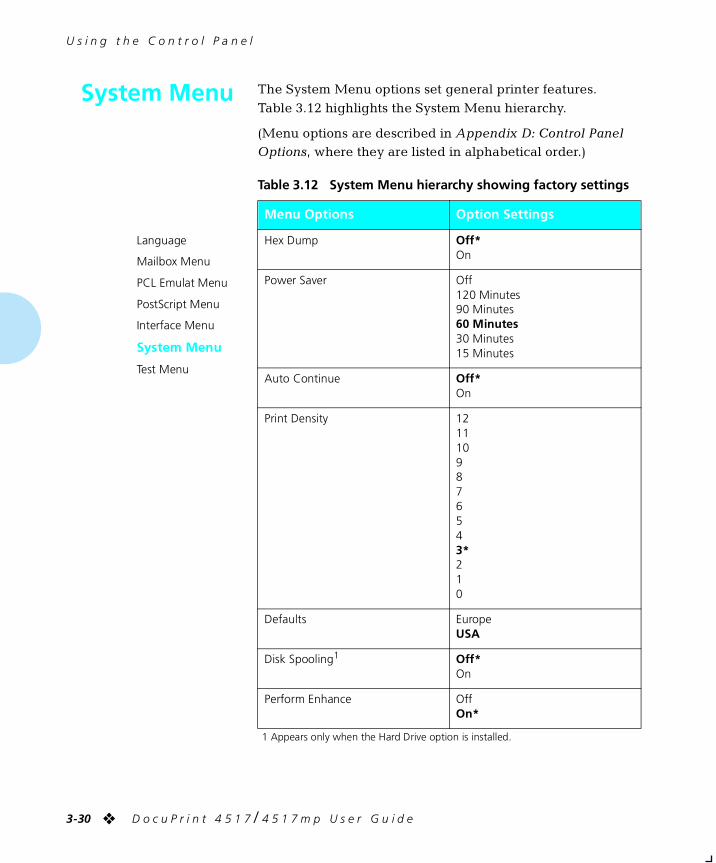
U s i n g t h e C o n t r o l P a n e l
3-30 ❖ D o c u P r i n t 4 5 1 7 / 4 5 1 7 m p U s e r G u i d e
System Menu The System Menu options set general printer features.
Table 3.12 highlights the System Menu hierarchy.
(Menu options are described in Appendix D: Control Panel Options, where they are listed in alphabetical order.)
1 Appears only when the Hard Drive option is installed.
Table 3.12 System Menu hierarchy showing factory settings
Menu Options Option Settings
Language
Mailbox Menu
PCL Emulat Menu
PostScript Menu
Interface Menu
System Menu
Test Menu
Hex Dump Off*On
Power Saver Off120 Minutes90 Minutes60 Minutes30 Minutes15 Minutes
Auto Continue Off*On
Print Density 1211109876543*210
Defaults EuropeUSA
Disk Spooling1 Off*On
Perform Enhance OffOn*
chapter3.frm Page 30 Friday, July 11, 1997 8:15 PM
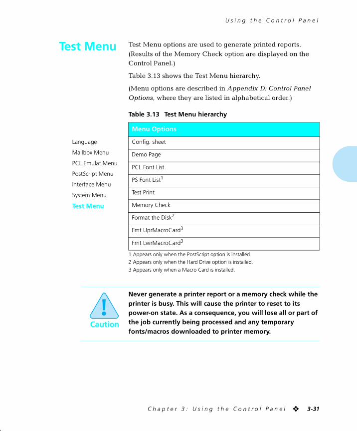
U s i n g t h e C o n t r o l P a n e l
C h a p t e r 3 : U s i n g t h e C o n t r o l P a n e l ❖ 3-31
Test Menu Test Menu options are used to generate printed reports.
(Results of the Memory Check option are displayed on the Control Panel.)
Table 3.13 shows the Test Menu hierarchy.
(Menu options are described in Appendix D: Control Panel
Options, where they are listed in alphabetical order.)
1 Appears only when the PostScript option is installed.
2 Appears only when the Hard Drive option is installed.
3 Appears only when a Macro Card is installed.
Table 3.13 Test Menu hierarchy
Menu Options
Language
Mailbox Menu
PCL Emulat Menu
PostScript Menu
Interface Menu
System Menu
Test Menu
Config. sheet
Demo Page
PCL Font List
PS Font List1
Test Print
Memory Check
Format the Disk2
Fmt UprMacroCard3
Fmt LwrMacroCard3
Caution
Never generate a printer report or a memory check while the printer is busy. This will cause the printer to reset to its power-on state. As a consequence, you will lose all or part of the job currently being processed and any temporary fonts/macros downloaded to printer memory.
chapter3.frm Page 31 Friday, July 11, 1997 8:15 PM
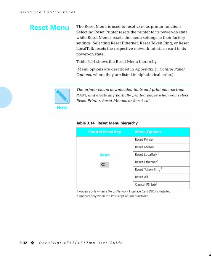
U s i n g t h e C o n t r o l P a n e l
3-32 ❖ D o c u P r i n t 4 5 1 7 / 4 5 1 7 m p U s e r G u i d e
Reset Menu The Reset Menu is used to reset various printer functions.
Selecting Reset Printer resets the printer to its power-on state, while Reset Menus resets the menu settings to their factory settings. Selecting Reset Ethernet, Reset Token Ring, or Reset
LocalTalk resets the respective network interface card to its power-on state.
Table 3.14 shows the Reset Menu hierarchy.
(Menu options are described in Appendix D: Control Panel Options, where they are listed in alphabetical order.)
1 Appears only when a Xerox Network Interface Card (NIC) is installed.
2 Appears only when the PostScript option is installed.
Note
The printer clears downloaded fonts and print macros from
RAM, and ejects any partially printed pages when you select Reset Printer, Reset Menus, or Reset All.
Table 3.14 Reset Menu hierarchy
Control Panel Key Menu Options
Reset
Reset Printer
Reset Menus
Reset LocalTalk1
Reset Ethernet1
Reset Token Ring1
Reset All
Cancel PS Job2
chapter3.frm Page 32 Friday, July 11, 1997 8:15 PM
Chapter 4
C h a p t e r 4 : D o c u P r i n t 4 5 1 7 P r i n t e r D r i v e r s ❖ 4-1
DocuPrint 4517 Printer Drivers Chapter4
DocuPrint 4517 PCL 5e Emulation Printer Drivers .............. 4-2
DocuPrint 4517 PostScript Printer Drivers .......................... 4-3
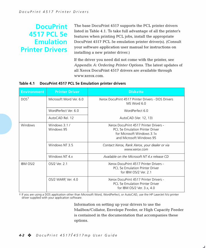
D o c u P r i n t 4 5 1 7 P r i n t e r D r i v e r s
4-2 ❖ D o c u P r i n t 4 5 1 7 / 4 5 1 7 m p U s e r G u i d e
DocuPrint4517 PCL 5e
EmulationPrinter Drivers
The base DocuPrint 4517 supports the PCL printer drivers
listed in Table 4.1. To take full advantage of all the printer’s features when printing PCL jobs, install the appropriate DocuPrint 4517 PCL 5e emulation printer driver(s). (Consult
your software application user manual for instructions on installing a new printer driver.)
If the driver you need did not come with the printer, see
Appendix A: Ordering Printer Options. The latest updates of all Xerox DocuPrint 4517 drivers are available through www.xerox.com.
Information on setting up your drivers to use the Mailbox/Collator, Envelope Feeder, or High Capacity Feeder
is contained in the documentation that accompanies these options.
† If you are using a DOS application other than Microsoft Word, WordPerfect, or AutoCAD, use the HP LaserJet IVsi printer driver supplied with your application software.
Table 4.1 DocuPrint 4517 PCL 5e Emulation printer drivers
Environment Printer Driver Diskette
DOS† Microsoft Word Ver. 6.0 Xerox DocuPrint 4517 Printer Drivers - DOS DriversMS Word 6.0
WordPerfect Ver. 6.0 WordPerfect 6.0
AutoCAD Rel. 12 AutoCAD (Ver. 12, 13)
Windows Windows 3.1 / Windows 95
Xerox DocuPrint 4517 Printer Drivers -PCL 5e Emulation Printer Driver
for Microsoft Windows 3.1xand Microsoft Windows 95
Windows NT 3.5 Contact Xerox, Rank Xerox, your dealer or viawww.xerox.com
Windows NT 4.x Available on the Microsoft NT 4.x release CD
IBM OS/2 OS/2 Ver. 2.1 Xerox DocuPrint 4517 Printer Drivers -PCL 5e Emulation Printer Driver
for IBM OS/2 Ver. 2.1
OS/2 WARP, Ver. 4.0 Xerox DocuPrint 4517 Printer Drivers -PCL 5e Emulation Printer Driver
for IBM OS/2 Ver. 3.x, 4.0
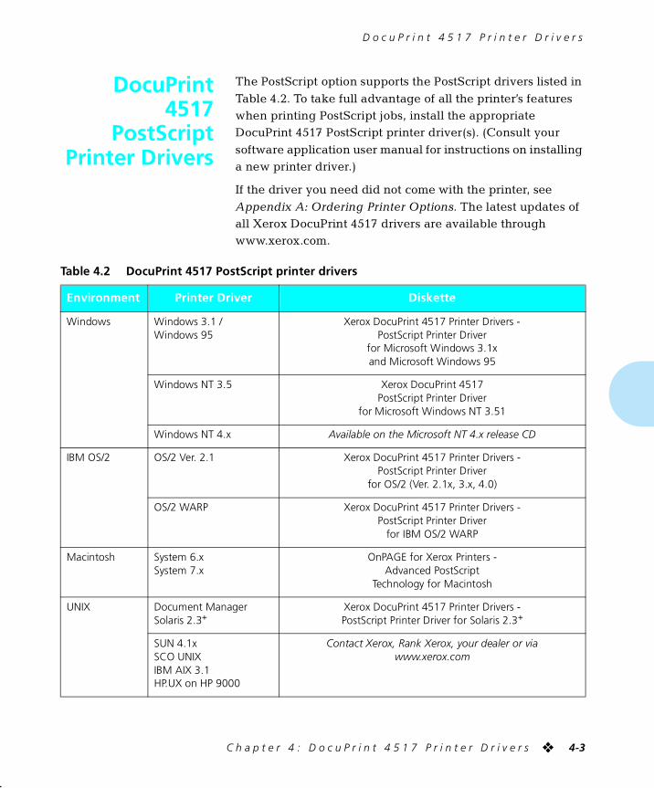
D o c u P r i n t 4 5 1 7 P r i n t e r D r i v e r s
C h a p t e r 4 : D o c u P r i n t 4 5 1 7 P r i n t e r D r i v e r s ❖ 4-3
DocuPrint4517
PostScriptPrinter Drivers
The PostScript option supports the PostScript drivers listed in
Table 4.2. To take full advantage of all the printer’s features when printing PostScript jobs, install the appropriate DocuPrint 4517 PostScript printer driver(s). (Consult your
software application user manual for instructions on installing a new printer driver.)
If the driver you need did not come with the printer, see
Appendix A: Ordering Printer Options. The latest updates of all Xerox DocuPrint 4517 drivers are available through www.xerox.com.
Table 4.2 DocuPrint 4517 PostScript printer drivers
Environment Printer Driver Diskette
Windows Windows 3.1 /Windows 95
Xerox DocuPrint 4517 Printer Drivers -PostScript Printer Driver
for Microsoft Windows 3.1xand Microsoft Windows 95
Windows NT 3.5 Xerox DocuPrint 4517PostScript Printer Driver
for Microsoft Windows NT 3.51
Windows NT 4.x Available on the Microsoft NT 4.x release CD
IBM OS/2 OS/2 Ver. 2.1 Xerox DocuPrint 4517 Printer Drivers -PostScript Printer Driver
for OS/2 (Ver. 2.1x, 3.x, 4.0)
OS/2 WARP Xerox DocuPrint 4517 Printer Drivers -PostScript Printer Driver
for IBM OS/2 WARP
Macintosh System 6.xSystem 7.x
OnPAGE for Xerox Printers -Advanced PostScript
Technology for Macintosh
UNIX Document ManagerSolaris 2.3+
Xerox DocuPrint 4517 Printer Drivers -PostScript Printer Driver for Solaris 2.3+
SUN 4.1xSCO UNIXIBM AIX 3.1HP.UX on HP 9000
Contact Xerox, Rank Xerox, your dealer or viawww.xerox.com

D o c u P r i n t 4 5 1 7 P o s t S c r i p t P r i n t e r D r i v e r s
4-4 ❖ D o c u P r i n t 4 5 1 7 / 4 5 1 7 m p U s e r G u i d e
Information on setting up your drivers to use the
Mailbox/Collator, Envelope Feeder, or High Capacity Feeder is contained in the documentation that accompanies these options.
Chapter 5
C h a p t e r 5 : U s i n g t h e H a r d D r i v e / D o w n l o a d i n g F o n t s ❖ 5-1
Using the Hard Drive / Downloading Fonts Chapter5
Hard Drive Considerations ................................................... 5-2
Print/Disk Spooling ............................................................... 5-2
State Saving ......................................................................... 5-2
Formatting the Hard Drive .................................................... 5-3
Downloading Fonts and Macros ......................................... 5-4
chapter5.frm Page 1 Friday, July 11, 1997 8:18 PM
U s i n g t h e H a r d D r i v e / D o w n l o a d i n g F o n t s
5-2 ❖ D o c u P r i n t 4 5 1 7 / 4 5 1 7 m p U s e r G u i d e
Hard DriveConsiderations
If you install the optional hard drive on the DocuPrint 4517, it
will significantly increase the amount of memory available for processing jobs and storing downloaded information (such as fonts and macros).
Print/DiskSpooling
The hard drive can function as a print spooler when you set
the Disk Spooling option to On. With disk spooling enabled, the hard drive simultaneously accepts print jobs from all enabled ports, then processes and prints them in the
order in which they are first received.
Disk spooling is useful for both standalone and networked systems:
• When the printer is busy processing a long or complex
print job, successive print jobs from the same or other ports can be accepted by the printer and spooled to the hard disk. Accordingly, the printer will free the computer
that is submitting print jobs so it can subsequently switch to tasks other than printing.
• While most networks provide spooling outside the printer,
spooling to a disk inside the printer will remove network related overhead. Accepting print jobs from a disk in the printer is more efficient than accepting print jobs one at a
time from networks.
The number of jobs that can be spooled is limited by the amount of hard drive space available. Also, spooling from networks will not be supported for AppleTalk jobs.
State Saving When the State Saving option is set to On, the printer
saves downloaded information when it switches between the PCL and PostScript PDLs (Printer Description Language). Installing a hard drive increases the amount of memory the
printer has available for saving downloaded fonts and macros when it switches between PDLs.
chapter5.frm Page 2 Friday, July 11, 1997 8:18 PM
H a r d D r i v e C o n s i d e r a t i o n s
C h a p t e r 5 : U s i n g t h e H a r d D r i v e / D o w n l o a d i n g F o n t s ❖ 5-3
Formatting theHard Drive
When a new unformatted hard disk drive is installed in the
printer, it must be formatted before it will be available for use. Formatting can be done when the printer is powered on after the installation.
The disk can be reformatted at any time. This is useful when it is desired to erase everything on the disk—all fonts, macros, and spooled print data. Also, in the unusual case of a problem
with the disk, it may be desirable to reformat it, again at the expense of erasing everything on it.
Formatting is accomplished by selecting the Format the
Disk option in the Test Menu. You will be warned of losing data and asked two times to confirm the formatting by pressing Up .
chapter5.frm Page 3 Friday, July 11, 1997 8:18 PM
U s i n g t h e H a r d D r i v e / D o w n l o a d i n g F o n t s
5-4 ❖ D o c u P r i n t 4 5 1 7 / 4 5 1 7 m p U s e r G u i d e
DownloadingFonts and
Macros
Xerox DocuPrint 4517 printer drivers provide you with the
ability to download fonts and PCL 5e macros to the printer.
Fonts can be downloaded to printer memory or to the optional hard drive. Macros can be downloaded to printer memory, the
optional hard drive, or a Xerox macro card (if one is installed).
• To download fonts you must first install the appropriate DocuPrint 4517 Windows 3.1/’95, Macintosh, Windows NT,
or UNIX drivers. To download macros, you must install the DocuPrint 4517 Windows PCL 5e driver.
• Fonts and macros downloaded to the hard drive are stored on the hard drive until you delete them. Turning
the printer power off does not clear these fonts/macros from the hard drive.
You can only delete a macro from the hard drive or the
macro card if you know the macro ID#. You should therefore keep a record of downloaded macros. (You cannot print out a list of macros.)
• PCL 5e fonts are available from Xerox via Xerox font
cards. Turning the printer power off does not clear these fonts from the font cards. You cannot download fonts to these cards.
• The Xerox macro cards contain flash memory which allows you to download and store PCL 5e macros. Instructions are in the Read Me file of the drivers. Turning
the printer power off does not clear these macros from the macro cards.
• “Temporary” fonts/macros downloaded to printer memory, on a job basis, are cleared from the printer’s
memory after each job.
chapter5.frm Page 4 Friday, July 11, 1997 8:18 PM
D o w n l o a d i n g F o n t s a n d M a c r o s
C h a p t e r 5 : U s i n g t h e H a r d D r i v e / D o w n l o a d i n g F o n t s ❖ 5-5
• “Permanent” fonts downloaded to printer memory are
cleared from the printer’s memory whenever the printer is powered off, and when the printer switches PDLs and the State Saving option is set to Off.
(When State Saving is set to On, “permanent” fonts/macros are only cleared from printer memory when you turn off the printer.)
Note
For further information on how to download and delete PCL macros, refer to the section “PCL Macro Commands” (page G-8) in Appendix G: DocuPrint 4517 Unique Printer
Commands.
For further information on how to create and use PCL macros, refer to the respective DocuPrint 4517 PCL driver help.
chapter5.frm Page 5 Friday, July 11, 1997 8:18 PM

5-6 ❖ D o c u P r i n t 4 5 1 7 / 4 5 1 7 m p U s e r G u i d e
chapter5.frm Page 6 Friday, July 11, 1997 8:18 PM
Chapter 6
C h a p t e r 6 : T r o u b l e s h o o t i n g ❖ 6-1
Troubleshooting Chapter6
Printer Operation Problems ................................................. 6-2
Control Panel Messages ....................................................... 6-6
Diagnostic LED Flash Sequences ........................................ 6-28
Paper Jams .......................................................................... 6-29
What Causes a Paper Jam? ................................................. 6-29
Clearing Paper Jams ........................................................... 6-29
Print Quality Problems ....................................................... 6-37
chapter6.frm Page 1 Friday, July 11, 1997 8:19 PM
T r o u b l e s h o o t i n g
6-2 ❖ D o c u P r i n t 4 5 1 7 / 4 5 1 7 m p U s e r G u i d e
PrinterOperationProblems
Consult Table 6.1 starting on page 6-3 for corrective actions
when the printer will not print or when the printed output is not what you expect.
chapter6.frm Page 2 Friday, July 11, 1997 8:19 PM
P r i n t e r O p e r a t i o n P r o b l e m s
C h a p t e r 6 : T r o u b l e s h o o t i n g ❖ 6-3
Table 6.1 Printer operation problems
Problem Action
The printer will not print. 1. Power the printer OFF, then ON.
2. Print a Configuration Sheet.
• If it prints, the printer is okay.
• If it does not print, contact your dealer or Xerox/Rank Xerox.
A file sent from the host does not print.
1. Make sure the printer is online.
2. Send a plain text file (i.e., one without printing commands embedded in it) to the printer.
• If the file prints correctly in the default font, with all of the characters in the original file, the printer is seeing the same data that the host is sending, and the interface or communication line is functioning correctly.
• If no data prints (or the last page indicator does not come on):
A. Make certain the printer is configured properly.
B. The port (parallel or network) may be disabled on the printer. Check the Configuration Sheet for the port you are using to see if the Port Enable option in the appropriate Interface Menu is set to On. If it is set to Off, set it to On and try again.
C. If using an optional Xerox Network Interface Card (XNIC) for Ethernet, LocalTalk, or Token Ring, check the Configuration Sheet to see if the printer is acknowledging that the XNIC is present. (Refer to XNIC installation instructions in Appendix C: Installing and Removing Printer Options.)
• If the Configuration Sheet shows the XNIC as “failed,” or does not show the XNIC as present, power OFF the printer and unplug it. Pull out the controller board, remove the XNIC, and check that the connector pins are not bent. If bent, straighten. Reseat the XNIC securely, put the controller board back in the printer, power ON and print another Configuration Sheet. If the Configuration Sheet still shows the XNIC as “failed,” the XNIC has failed. If the Configuration Sheet still does not show the XNIC as present, then either the XNIC has failed or the interface between the XNIC and the printer controller has failed. Contact your dealer or Xerox/Rank Xerox.
• If the Configuration Sheet shows the network card as present, check if the printer is recognized by the host. (Refer to the Troubleshooting chapter of the respective XNIC Configuration Guide.)
D. If there is garbled data, check the Configuration Sheet to confirm that the correct emulation is selected or that the Language Sensing option is set to On.
Table 6.1 Page 1 of 3
chapter6.frm Page 3 Friday, July 11, 1997 8:19 PM
P r i n t e r O p e r a t i o n P r o b l e m s
6-4 ❖ D o c u P r i n t 4 5 1 7 / 4 5 1 7 m p U s e r G u i d e
A printed page does not look like it should.
1. Make certain that the software application you are using to create your print job is configured properly. Refer to your software documentation.
2. Send a file containing PCL or PostScript commands to the printer.
• If your page prints as it should, your printer and interface are functioning properly.
• If your information prints correctly, but doesn’t look right, you may have:
• An error in your command sequence/operator
• A missing downloaded font
• A mismatched printer option against your host formatting
• A missing or misaligned font card
• Command errors may be identified by looking at your input file or by using the Hex Dump feature on the printer. You can determine which fonts are in the system by printing a PCL or PS Font List. You can verify your data setup by printing a Configuration Sheet and checking your printer setup.
The requested font for the job—a font on a font card—does not print.
Print a PCL Font List.
• If fonts print on the Font List, your print job may need correcting.
• If fonts do not print on the Font List, power the printer OFF, remove and reinstall the font card. Power the printer back ON, and print another PCL Font List.
• If the font card is still not being recognized, try another slot or font card, then print another Font List.
• If a different font slot works, contact your dealer or Xerox/Rank Xerox to correct the defective slot.
• If a new font card is recognized, contact your dealer or Xerox/Rank Xerox to replace the defective card.
PostScript commands are printed instead of the PostScript job.
1. Make certain that the software application you are using to create your job is configured properly. Refer to your software documentation.
2. If the Lang. Sensing option in the appropriate Interface Menu is set to On, the job sent to the printer might have included an incorrect header and therefore not have indicated that a PostScript job was being sent.
• Set the System Language option in the appropriate Interface Menu to PostScript and try sending the job again.
• Check your software to make sure the PostScript header file is being sent to the printer.
Table 6.1 Printer operation problems (continued)
Problem Action
Table 6.1 Page 2 of 3
chapter6.frm Page 4 Friday, July 11, 1997 8:19 PM
P r i n t e r O p e r a t i o n P r o b l e m s
C h a p t e r 6 : T r o u b l e s h o o t i n g ❖ 6-5
The job does not print in the requested font.
Check the spelling of the requested font in your PostScript file. Many times a typo is the problem. If the font is spelled correctly, print a PS Font List to check if the font is present. If it is not, download the font and resend the job.
The bottom edge of the page is cut off, or there are white bands.
For PCL jobs, set the Page Protection option in the PCL Emulat Menu to the size of the paper for the job (or to the next larger size).
For PostScript jobs, set the Page Protection option in the PostScript Menu to On.
A PCL job prints, but the edges are cut off.
Set the Edge to Edge option in the PCL Emulat Menu to On.
A PostScript job fails to print.
1. Check that PostScript is installed; also check that you are using a DocuPrint 4517 PostScript printer driver.
2. If the Lang. Sensing option in the appropriate Interface Menu is set to On, set the System Language option to PostScript and re-send the job.
3. Set the Print Errors option in the PostScript Menu to On and resend the job.
• If an error page prints, there is a problem in the PostScript coding. Correct the coding problem and resend the job.
• If the job does not print and no error page was printed, set the Page Protection option in the PostScript Menu to Off.
• If the job still does not print, the job may require additional memory.
Jobs printed from the front tray are skewed with respect to the sheet/envelope.
Check the side guide to be sure that it is snug against the right side of the sheet but not so tight as to buckle it.
Table 6.1 Printer operation problems (continued)
Problem Action
Table 6.1 Page 3 of 3
chapter6.frm Page 5 Friday, July 11, 1997 8:19 PM
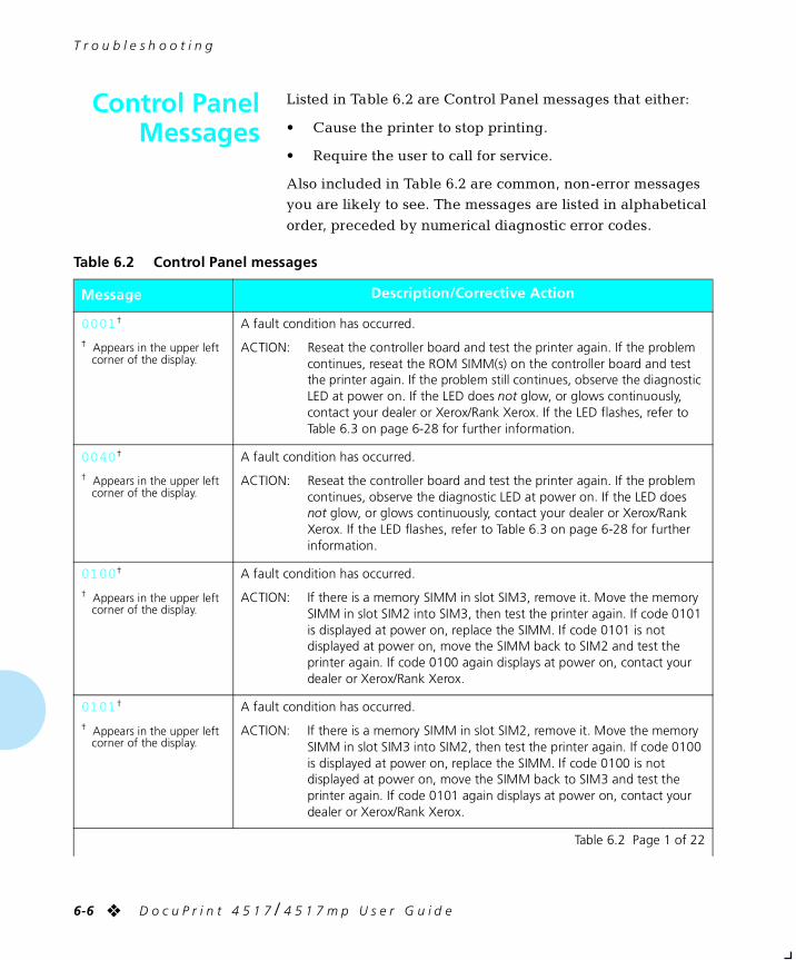
T r o u b l e s h o o t i n g
6-6 ❖ D o c u P r i n t 4 5 1 7 / 4 5 1 7 m p U s e r G u i d e
Control PanelMessages
Listed in Table 6.2 are Control Panel messages that either:
• Cause the printer to stop printing.
• Require the user to call for service.
Also included in Table 6.2 are common, non-error messages you are likely to see. The messages are listed in alphabetical
order, preceded by numerical diagnostic error codes.
Table 6.2 Control Panel messages
Message Description/Corrective Action
0001 †
† Appears in the upper left corner of the display.
A fault condition has occurred.
ACTION: Reseat the controller board and test the printer again. If the problem continues, reseat the ROM SIMM(s) on the controller board and test the printer again. If the problem still continues, observe the diagnostic LED at power on. If the LED does not glow, or glows continuously, contact your dealer or Xerox/Rank Xerox. If the LED flashes, refer to Table 6.3 on page 6-28 for further information.
0040 †
† Appears in the upper left corner of the display.
A fault condition has occurred.
ACTION: Reseat the controller board and test the printer again. If the problem continues, observe the diagnostic LED at power on. If the LED does not glow, or glows continuously, contact your dealer or Xerox/Rank Xerox. If the LED flashes, refer to Table 6.3 on page 6-28 for further information.
0100 †
† Appears in the upper left corner of the display.
A fault condition has occurred.
ACTION: If there is a memory SIMM in slot SIM3, remove it. Move the memory SIMM in slot SIM2 into SIM3, then test the printer again. If code 0101 is displayed at power on, replace the SIMM. If code 0101 is not displayed at power on, move the SIMM back to SIM2 and test the printer again. If code 0100 again displays at power on, contact your dealer or Xerox/Rank Xerox.
0101 †
† Appears in the upper left corner of the display.
A fault condition has occurred.
ACTION: If there is a memory SIMM in slot SIM2, remove it. Move the memory SIMM in slot SIM3 into SIM2, then test the printer again. If code 0100 is displayed at power on, replace the SIMM. If code 0100 is not displayed at power on, move the SIMM back to SIM3 and test the printer again. If code 0101 again displays at power on, contact your dealer or Xerox/Rank Xerox.
Table 6.2 Page 1 of 22
chapter6.frm Page 6 Friday, July 11, 1997 8:19 PM
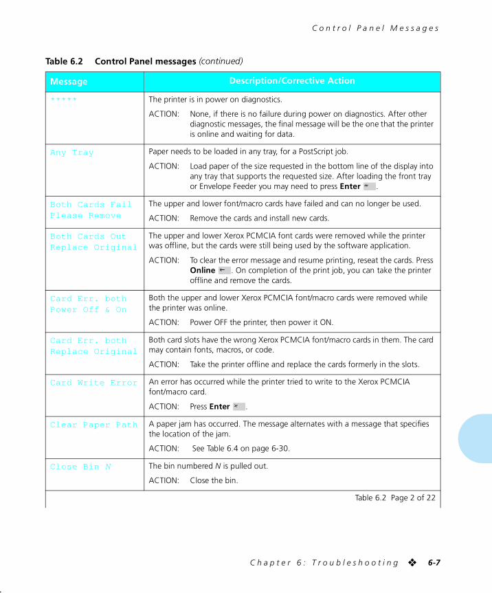
C o n t r o l P a n e l M e s s a g e s
C h a p t e r 6 : T r o u b l e s h o o t i n g ❖ 6-7
***** The printer is in power on diagnostics.
ACTION: None, if there is no failure during power on diagnostics. After other diagnostic messages, the final message will be the one that the printer is online and waiting for data.
Any Tray Paper needs to be loaded in any tray, for a PostScript job.
ACTION: Load paper of the size requested in the bottom line of the display into any tray that supports the requested size. After loading the front tray or Envelope Feeder you may need to press Enter .
Both Cards FailPlease Remove
The upper and lower font/macro cards have failed and can no longer be used.
ACTION: Remove the cards and install new cards.
Both Cards OutReplace Original
The upper and lower Xerox PCMCIA font cards were removed while the printer was offline, but the cards were still being used by the software application.
ACTION: To clear the error message and resume printing, reseat the cards. Press Online . On completion of the print job, you can take the printer offline and remove the cards.
Card Err. bothPower Off & On
Both the upper and lower Xerox PCMCIA font/macro cards were removed while the printer was online.
ACTION: Power OFF the printer, then power it ON.
Card Err. bothReplace Original
Both card slots have the wrong Xerox PCMCIA font/macro cards in them. The card may contain fonts, macros, or code.
ACTION: Take the printer offline and replace the cards formerly in the slots.
Card Write Error An error has occurred while the printer tried to write to the Xerox PCMCIA font/macro card.
ACTION: Press Enter .
Clear Paper Path A paper jam has occurred. The message alternates with a message that specifies the location of the jam.
ACTION: See Table 6.4 on page 6-30.
Close Bin N The bin numbered N is pulled out.
ACTION: Close the bin.
Table 6.2 Control Panel messages (continued)
Message Description/Corrective Action
Table 6.2 Page 2 of 22
chapter6.frm Page 7 Friday, July 11, 1997 8:19 PM
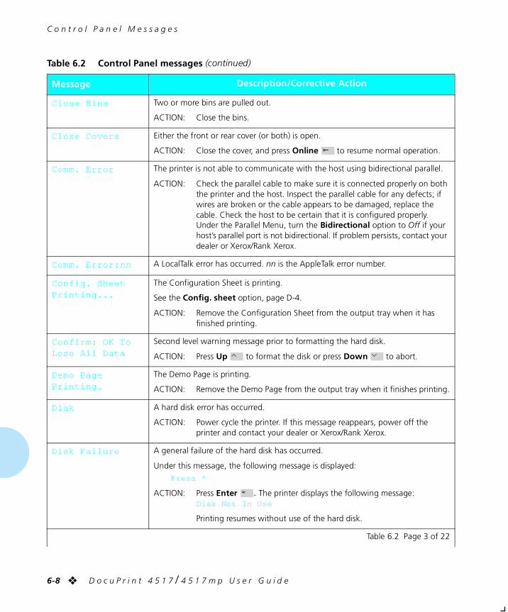
C o n t r o l P a n e l M e s s a g e s
6-8 ❖ D o c u P r i n t 4 5 1 7 / 4 5 1 7 m p U s e r G u i d e
Close Bins Two or more bins are pulled out.
ACTION: Close the bins.
Close Covers Either the front or rear cover (or both) is open.
ACTION: Close the cover, and press Online to resume normal operation.
Comm. Error The printer is not able to communicate with the host using bidirectional parallel.
ACTION: Check the parallel cable to make sure it is connected properly on both the printer and the host. Inspect the parallel cable for any defects; if wires are broken or the cable appears to be damaged, replace the cable. Check the host to be certain that it is configured properly. Under the Parallel Menu, turn the Bidirectional option to Off if your host’s parallel port is not bidirectional. If problem persists, contact your dealer or Xerox/Rank Xerox.
Comm. Error: nn A LocalTalk error has occurred. nn is the AppleTalk error number.
Config. Sheet Printing...
The Configuration Sheet is printing.
See the Config. sheet option, page D-4.
ACTION: Remove the Configuration Sheet from the output tray when it has finished printing.
Confirm: OK ToLose All Data
Second level warning message prior to formatting the hard disk.
ACTION: Press Up to format the disk or press Down to abort.
Demo PagePrinting…
The Demo Page is printing.
ACTION: Remove the Demo Page from the output tray when it finishes printing.
Disk A hard disk error has occurred.
ACTION: Power cycle the printer. If this message reappears, power off the printer and contact your dealer or Xerox/Rank Xerox.
Disk Failure A general failure of the hard disk has occurred.
Under this message, the following message is displayed:
Press *
ACTION: Press Enter . The printer displays the following message:Disk Not In Use
Printing resumes without use of the hard disk.
Table 6.2 Control Panel messages (continued)
Message Description/Corrective Action
Table 6.2 Page 3 of 22
chapter6.frm Page 8 Friday, July 11, 1997 8:19 PM
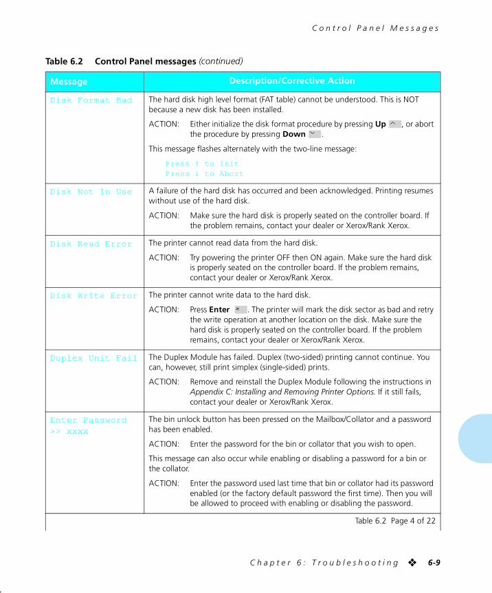
C o n t r o l P a n e l M e s s a g e s
C h a p t e r 6 : T r o u b l e s h o o t i n g ❖ 6-9
Disk Format Bad The hard disk high level format (FAT table) cannot be understood. This is NOT because a new disk has been installed.
ACTION: Either initialize the disk format procedure by pressing Up , or abort the procedure by pressing Down .
This message flashes alternately with the two-line message:
Press ↑ to InitPress ↓ to Abort
Disk Not In Use A failure of the hard disk has occurred and been acknowledged. Printing resumes without use of the hard disk.
ACTION: Make sure the hard disk is properly seated on the controller board. If the problem remains, contact your dealer or Xerox/Rank Xerox.
Disk Read Error The printer cannot read data from the hard disk.
ACTION: Try powering the printer OFF then ON again. Make sure the hard disk is properly seated on the controller board. If the problem remains, contact your dealer or Xerox/Rank Xerox.
Disk Write Error The printer cannot write data to the hard disk.
ACTION: Press Enter . The printer will mark the disk sector as bad and retry the write operation at another location on the disk. Make sure the hard disk is properly seated on the controller board. If the problem remains, contact your dealer or Xerox/Rank Xerox.
Duplex Unit Fail The Duplex Module has failed. Duplex (two-sided) printing cannot continue. You can, however, still print simplex (single-sided) prints.
ACTION: Remove and reinstall the Duplex Module following the instructions in Appendix C: Installing and Removing Printer Options. If it still fails, contact your dealer or Xerox/Rank Xerox.
Enter Password>> xxxx
The bin unlock button has been pressed on the Mailbox/Collator and a password has been enabled.
ACTION: Enter the password for the bin or collator that you wish to open.
This message can also occur while enabling or disabling a password for a bin or the collator.
ACTION: Enter the password used last time that bin or collator had its password enabled (or the factory default password the first time). Then you will be allowed to proceed with enabling or disabling the password.
Table 6.2 Control Panel messages (continued)
Message Description/Corrective Action
Table 6.2 Page 4 of 22
chapter6.frm Page 9 Friday, July 11, 1997 8:19 PM
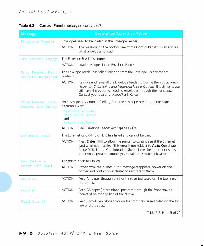
C o n t r o l P a n e l M e s s a g e s
6-10 ❖ D o c u P r i n t 4 5 1 7 / 4 5 1 7 m p U s e r G u i d e
Envelope Feeder Envelopes need to be loaded in the Envelope Feeder.
ACTION: The message on the bottom line of the Control Panel display advises what envelopes to load.
Env Feeder Empty The Envelope Feeder is empty.
ACTION: Load envelopes in the Envelope Feeder.
Env. Feeder FailService Required
The Envelope Feeder has failed. Printing from the Envelope Feeder cannot continue.
ACTION: Remove and reinstall the Envelope Feeder following the instructions in Appendix C: Installing and Removing Printer Options. If it still fails, you still have the option of feeding envelopes through the front tray. Contact your dealer or Xerox/Rank Xerox.
EnvelFeeder Jam-Remove All Envel
An envelope has jammed feeding from the Envelope Feeder. The message alternates with:
Remove EnvFeederOpen Front CoverandRemove Jam Envel
ACTION: See “Envelope Feeder Jam” (page 6-32).
Ethernet Fail The Ethernet card (XNIC-E’NET) has failed and cannot be used.
ACTION: Press Enter to allow the printer to continue as if the Ethernet card were not installed. This error is not subject to Auto Continue (page D-3). Print a Configuration Sheet. If the sheet does not show Ethernet as present, contact your dealer or Xerox/Rank Xerox.
Fan FailurePower Off NOW!
The printer’s fan has failed.
ACTION: Power cycle the printer. If this message reappears, power off the printer and contact your dealer or Xerox/Rank Xerox.
Feed A4 ACTION: Feed A4 paper through the front tray, as indicated on the top line of the display.
Feed A6 ACTION: Feed A6 paper (international postcard) through the front tray, as indicated on the top line of the display.
Feed Com-10 ACTION: Feed Com-10 envelope through the front tray, as indicated on the top line of the display.
Table 6.2 Control Panel messages (continued)
Message Description/Corrective Action
Table 6.2 Page 5 of 22
chapter6.frm Page 10 Friday, July 11, 1997 8:19 PM
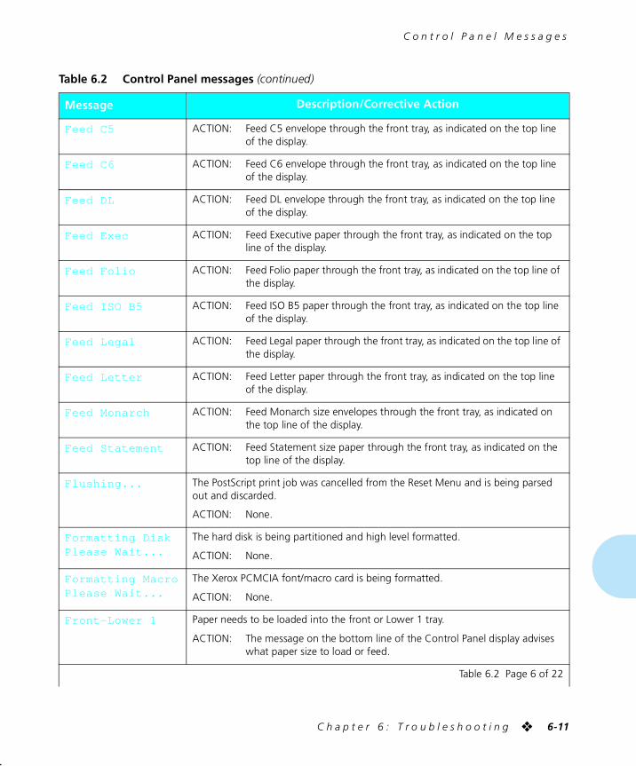
C o n t r o l P a n e l M e s s a g e s
C h a p t e r 6 : T r o u b l e s h o o t i n g ❖ 6-11
Feed C5 ACTION: Feed C5 envelope through the front tray, as indicated on the top line of the display.
Feed C6 ACTION: Feed C6 envelope through the front tray, as indicated on the top line of the display.
Feed DL ACTION: Feed DL envelope through the front tray, as indicated on the top line of the display.
Feed Exec ACTION: Feed Executive paper through the front tray, as indicated on the top line of the display.
Feed Folio ACTION: Feed Folio paper through the front tray, as indicated on the top line of the display.
Feed ISO B5 ACTION: Feed ISO B5 paper through the front tray, as indicated on the top line of the display.
Feed Legal ACTION: Feed Legal paper through the front tray, as indicated on the top line of the display.
Feed Letter ACTION: Feed Letter paper through the front tray, as indicated on the top line of the display.
Feed Monarch ACTION: Feed Monarch size envelopes through the front tray, as indicated on the top line of the display.
Feed Statement ACTION: Feed Statement size paper through the front tray, as indicated on the top line of the display.
Flushing... The PostScript print job was cancelled from the Reset Menu and is being parsed out and discarded.
ACTION: None.
Formatting DiskPlease Wait...
The hard disk is being partitioned and high level formatted.
ACTION: None.
Formatting MacroPlease Wait...
The Xerox PCMCIA font/macro card is being formatted.
ACTION: None.
Front-Lower 1 Paper needs to be loaded into the front or Lower 1 tray.
ACTION: The message on the bottom line of the Control Panel display advises what paper size to load or feed.
Table 6.2 Control Panel messages (continued)
Message Description/Corrective Action
Table 6.2 Page 6 of 22
chapter6.frm Page 11 Friday, July 11, 1997 8:19 PM
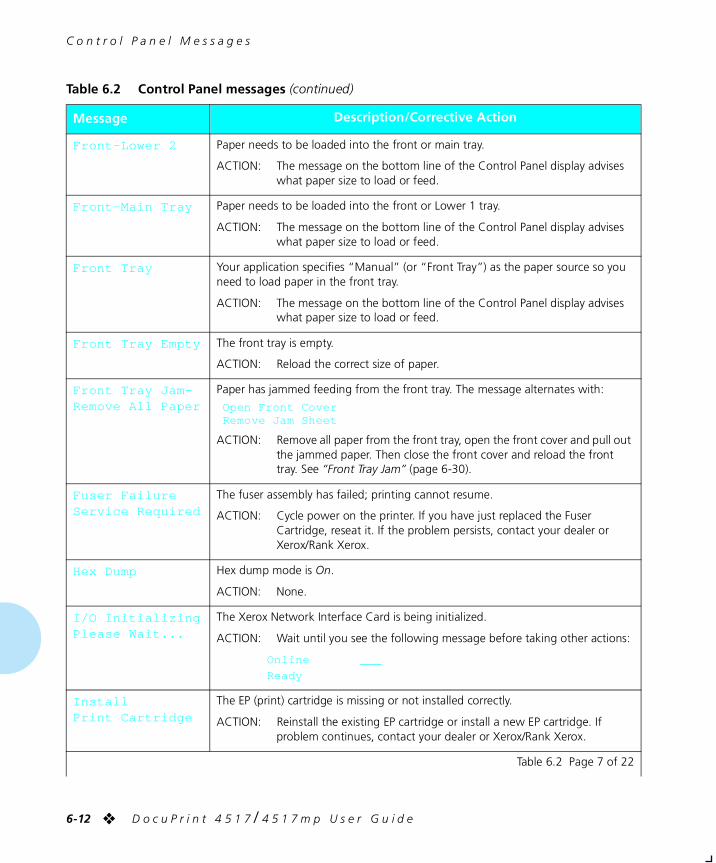
C o n t r o l P a n e l M e s s a g e s
6-12 ❖ D o c u P r i n t 4 5 1 7 / 4 5 1 7 m p U s e r G u i d e
Front-Lower 2 Paper needs to be loaded into the front or main tray.
ACTION: The message on the bottom line of the Control Panel display advises what paper size to load or feed.
Front-Main Tray Paper needs to be loaded into the front or Lower 1 tray.
ACTION: The message on the bottom line of the Control Panel display advises what paper size to load or feed.
Front Tray Your application specifies “Manual” (or “Front Tray”) as the paper source so you need to load paper in the front tray.
ACTION: The message on the bottom line of the Control Panel display advises what paper size to load or feed.
Front Tray Empty The front tray is empty.
ACTION: Reload the correct size of paper.
Front Tray Jam-Remove All Paper
Paper has jammed feeding from the front tray. The message alternates with:
Open Front CoverRemove Jam Sheet
ACTION: Remove all paper from the front tray, open the front cover and pull out the jammed paper. Then close the front cover and reload the front tray. See “Front Tray Jam” (page 6-30).
Fuser FailureService Required
The fuser assembly has failed; printing cannot resume.
ACTION: Cycle power on the printer. If you have just replaced the Fuser Cartridge, reseat it. If the problem persists, contact your dealer or Xerox/Rank Xerox.
Hex Dump Hex dump mode is On.
ACTION: None.
I/O InitializingPlease Wait...
The Xerox Network Interface Card is being initialized.
ACTION: Wait until you see the following message before taking other actions:
Online ___
Ready
InstallPrint Cartridge
The EP (print) cartridge is missing or not installed correctly.
ACTION: Reinstall the existing EP cartridge or install a new EP cartridge. If problem continues, contact your dealer or Xerox/Rank Xerox.
Table 6.2 Control Panel messages (continued)
Message Description/Corrective Action
Table 6.2 Page 7 of 22
chapter6.frm Page 12 Friday, July 11, 1997 8:19 PM
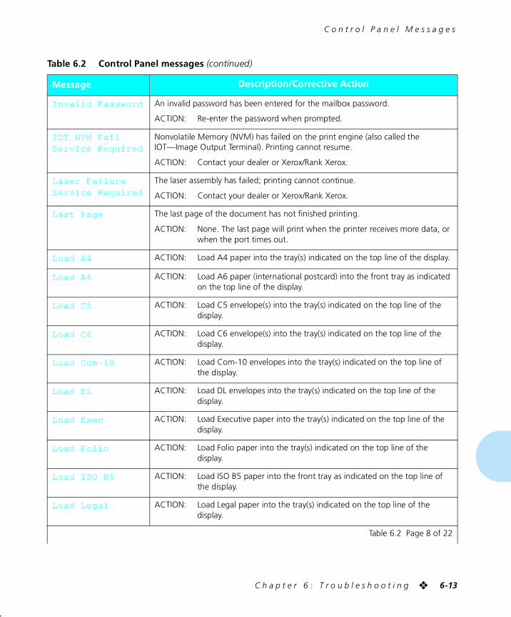
C o n t r o l P a n e l M e s s a g e s
C h a p t e r 6 : T r o u b l e s h o o t i n g ❖ 6-13
Invalid Password An invalid password has been entered for the mailbox password.
ACTION: Re-enter the password when prompted.
IOT NVM FailService Required
Nonvolatile Memory (NVM) has failed on the print engine (also called the IOT—Image Output Terminal). Printing cannot resume.
ACTION: Contact your dealer or Xerox/Rank Xerox.
Laser FailureService Required
The laser assembly has failed; printing cannot continue.
ACTION: Contact your dealer or Xerox/Rank Xerox.
Last Page The last page of the document has not finished printing.
ACTION: None. The last page will print when the printer receives more data, or when the port times out.
Load A4 ACTION: Load A4 paper into the tray(s) indicated on the top line of the display.
Load A6 ACTION: Load A6 paper (international postcard) into the front tray as indicated on the top line of the display.
Load C5 ACTION: Load C5 envelope(s) into the tray(s) indicated on the top line of the display.
Load C6 ACTION: Load C6 envelope(s) into the tray(s) indicated on the top line of the display.
Load Com-10 ACTION: Load Com-10 envelopes into the tray(s) indicated on the top line of the display.
Load DL ACTION: Load DL envelopes into the tray(s) indicated on the top line of the display.
Load Exec ACTION: Load Executive paper into the tray(s) indicated on the top line of the display.
Load Folio ACTION: Load Folio paper into the tray(s) indicated on the top line of the display.
Load ISO B5 ACTION: Load ISO B5 paper into the front tray as indicated on the top line of the display.
Load Legal ACTION: Load Legal paper into the tray(s) indicated on the top line of the display.
Table 6.2 Control Panel messages (continued)
Message Description/Corrective Action
Table 6.2 Page 8 of 22
chapter6.frm Page 13 Friday, July 11, 1997 8:19 PM
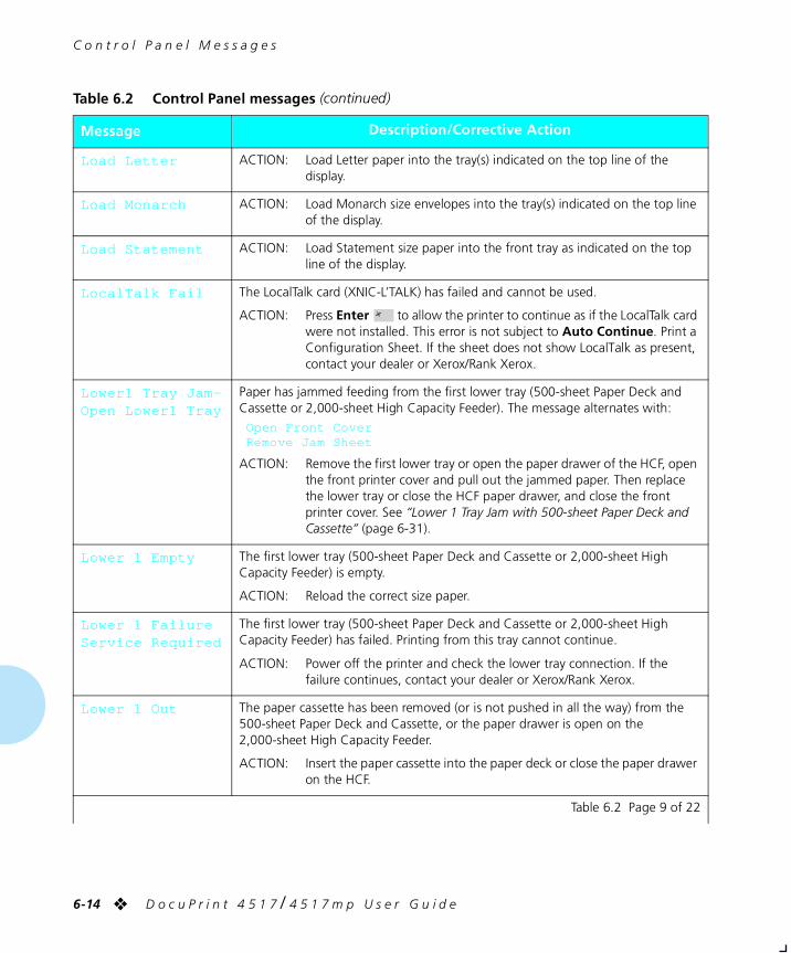
C o n t r o l P a n e l M e s s a g e s
6-14 ❖ D o c u P r i n t 4 5 1 7 / 4 5 1 7 m p U s e r G u i d e
Load Letter ACTION: Load Letter paper into the tray(s) indicated on the top line of the display.
Load Monarch ACTION: Load Monarch size envelopes into the tray(s) indicated on the top line of the display.
Load Statement ACTION: Load Statement size paper into the front tray as indicated on the top line of the display.
LocalTalk Fail The LocalTalk card (XNIC-L’TALK) has failed and cannot be used.
ACTION: Press Enter to allow the printer to continue as if the LocalTalk card were not installed. This error is not subject to Auto Continue. Print a Configuration Sheet. If the sheet does not show LocalTalk as present, contact your dealer or Xerox/Rank Xerox.
Lower1 Tray Jam-Open Lower1 Tray
Paper has jammed feeding from the first lower tray (500-sheet Paper Deck and Cassette or 2,000-sheet High Capacity Feeder). The message alternates with:
Open Front CoverRemove Jam Sheet
ACTION: Remove the first lower tray or open the paper drawer of the HCF, open the front printer cover and pull out the jammed paper. Then replace the lower tray or close the HCF paper drawer, and close the front printer cover. See “Lower 1 Tray Jam with 500-sheet Paper Deck and Cassette” (page 6-31).
Lower 1 Empty The first lower tray (500-sheet Paper Deck and Cassette or 2,000-sheet High Capacity Feeder) is empty.
ACTION: Reload the correct size paper.
Lower 1 FailureService Required
The first lower tray (500-sheet Paper Deck and Cassette or 2,000-sheet High Capacity Feeder) has failed. Printing from this tray cannot continue.
ACTION: Power off the printer and check the lower tray connection. If the failure continues, contact your dealer or Xerox/Rank Xerox.
Lower 1 Out The paper cassette has been removed (or is not pushed in all the way) from the 500-sheet Paper Deck and Cassette, or the paper drawer is open on the 2,000-sheet High Capacity Feeder.
ACTION: Insert the paper cassette into the paper deck or close the paper drawer on the HCF.
Table 6.2 Control Panel messages (continued)
Message Description/Corrective Action
Table 6.2 Page 9 of 22
chapter6.frm Page 14 Friday, July 11, 1997 8:19 PM
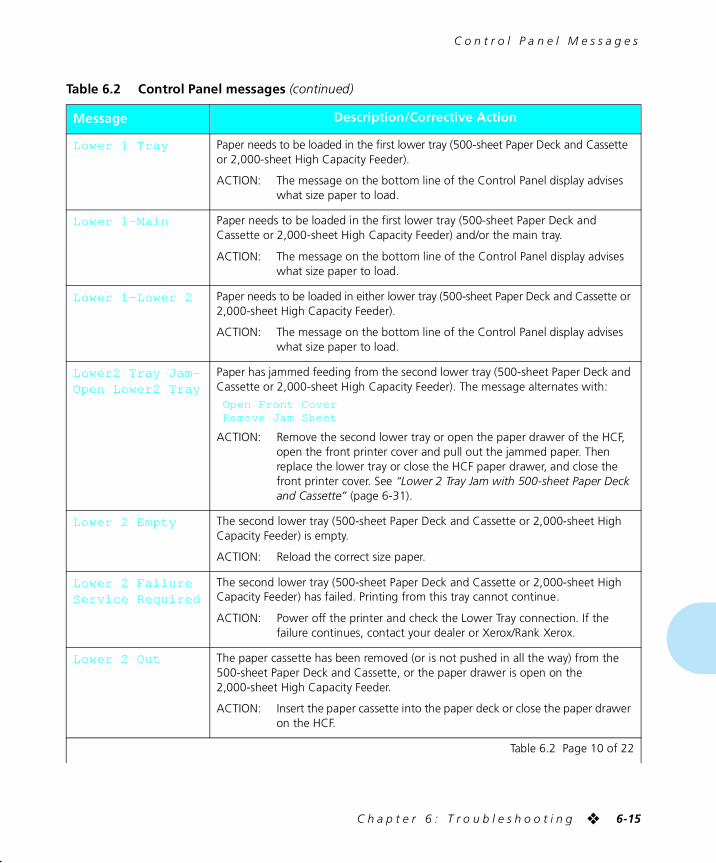
C o n t r o l P a n e l M e s s a g e s
C h a p t e r 6 : T r o u b l e s h o o t i n g ❖ 6-15
Lower 1 Tray Paper needs to be loaded in the first lower tray (500-sheet Paper Deck and Cassette or 2,000-sheet High Capacity Feeder).
ACTION: The message on the bottom line of the Control Panel display advises what size paper to load.
Lower 1-Main Paper needs to be loaded in the first lower tray (500-sheet Paper Deck and Cassette or 2,000-sheet High Capacity Feeder) and/or the main tray.
ACTION: The message on the bottom line of the Control Panel display advises what size paper to load.
Lower 1-Lower 2 Paper needs to be loaded in either lower tray (500-sheet Paper Deck and Cassette or 2,000-sheet High Capacity Feeder).
ACTION: The message on the bottom line of the Control Panel display advises what size paper to load.
Lower2 Tray Jam-Open Lower2 Tray
Paper has jammed feeding from the second lower tray (500-sheet Paper Deck and Cassette or 2,000-sheet High Capacity Feeder). The message alternates with:
Open Front CoverRemove Jam Sheet
ACTION: Remove the second lower tray or open the paper drawer of the HCF, open the front printer cover and pull out the jammed paper. Then replace the lower tray or close the HCF paper drawer, and close the front printer cover. See “Lower 2 Tray Jam with 500-sheet Paper Deck and Cassette” (page 6-31).
Lower 2 Empty The second lower tray (500-sheet Paper Deck and Cassette or 2,000-sheet High Capacity Feeder) is empty.
ACTION: Reload the correct size paper.
Lower 2 FailureService Required
The second lower tray (500-sheet Paper Deck and Cassette or 2,000-sheet High Capacity Feeder) has failed. Printing from this tray cannot continue.
ACTION: Power off the printer and check the Lower Tray connection. If the failure continues, contact your dealer or Xerox/Rank Xerox.
Lower 2 Out The paper cassette has been removed (or is not pushed in all the way) from the 500-sheet Paper Deck and Cassette, or the paper drawer is open on the 2,000-sheet High Capacity Feeder.
ACTION: Insert the paper cassette into the paper deck or close the paper drawer on the HCF.
Table 6.2 Control Panel messages (continued)
Message Description/Corrective Action
Table 6.2 Page 10 of 22
chapter6.frm Page 15 Friday, July 11, 1997 8:19 PM
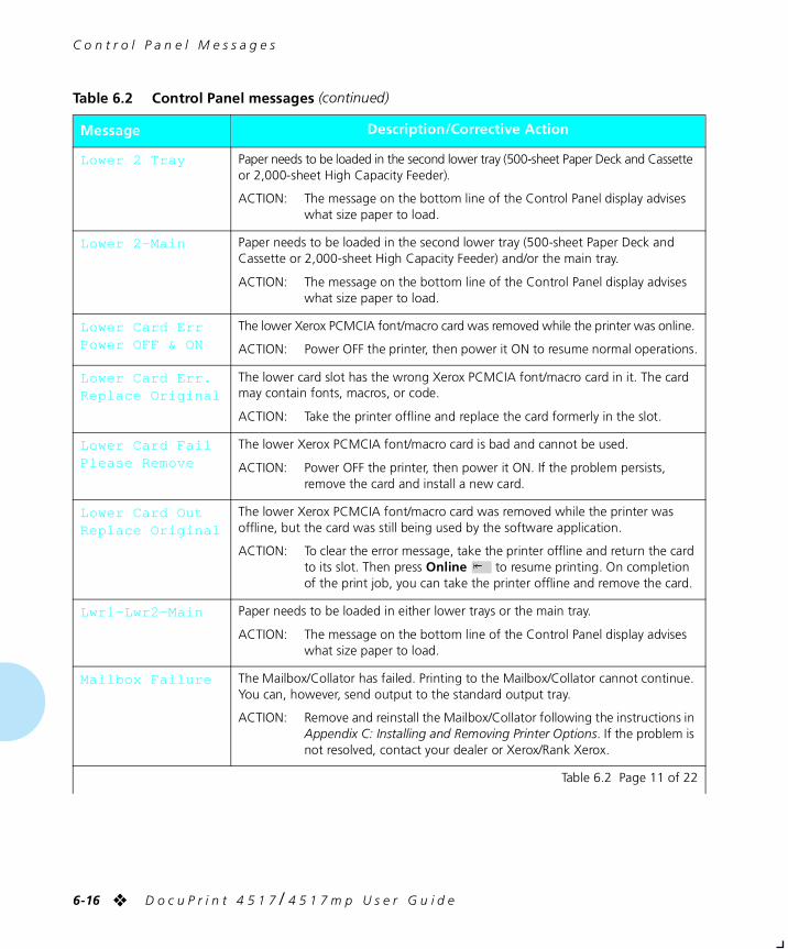
C o n t r o l P a n e l M e s s a g e s
6-16 ❖ D o c u P r i n t 4 5 1 7 / 4 5 1 7 m p U s e r G u i d e
Lower 2 Tray Paper needs to be loaded in the second lower tray (500-sheet Paper Deck and Cassette or 2,000-sheet High Capacity Feeder).
ACTION: The message on the bottom line of the Control Panel display advises what size paper to load.
Lower 2-Main Paper needs to be loaded in the second lower tray (500-sheet Paper Deck and Cassette or 2,000-sheet High Capacity Feeder) and/or the main tray.
ACTION: The message on the bottom line of the Control Panel display advises what size paper to load.
Lower Card ErrPower OFF & ON
The lower Xerox PCMCIA font/macro card was removed while the printer was online.
ACTION: Power OFF the printer, then power it ON to resume normal operations.
Lower Card Err.Replace Original
The lower card slot has the wrong Xerox PCMCIA font/macro card in it. The card may contain fonts, macros, or code.
ACTION: Take the printer offline and replace the card formerly in the slot.
Lower Card FailPlease Remove
The lower Xerox PCMCIA font/macro card is bad and cannot be used.
ACTION: Power OFF the printer, then power it ON. If the problem persists, remove the card and install a new card.
Lower Card OutReplace Original
The lower Xerox PCMCIA font/macro card was removed while the printer was offline, but the card was still being used by the software application.
ACTION: To clear the error message, take the printer offline and return the card to its slot. Then press Online to resume printing. On completion of the print job, you can take the printer offline and remove the card.
Lwr1-Lwr2-Main Paper needs to be loaded in either lower trays or the main tray.
ACTION: The message on the bottom line of the Control Panel display advises what size paper to load.
Mailbox Failure The Mailbox/Collator has failed. Printing to the Mailbox/Collator cannot continue. You can, however, send output to the standard output tray.
ACTION: Remove and reinstall the Mailbox/Collator following the instructions in Appendix C: Installing and Removing Printer Options. If the problem is not resolved, contact your dealer or Xerox/Rank Xerox.
Table 6.2 Control Panel messages (continued)
Message Description/Corrective Action
Table 6.2 Page 11 of 22
chapter6.frm Page 16 Friday, July 11, 1997 8:19 PM
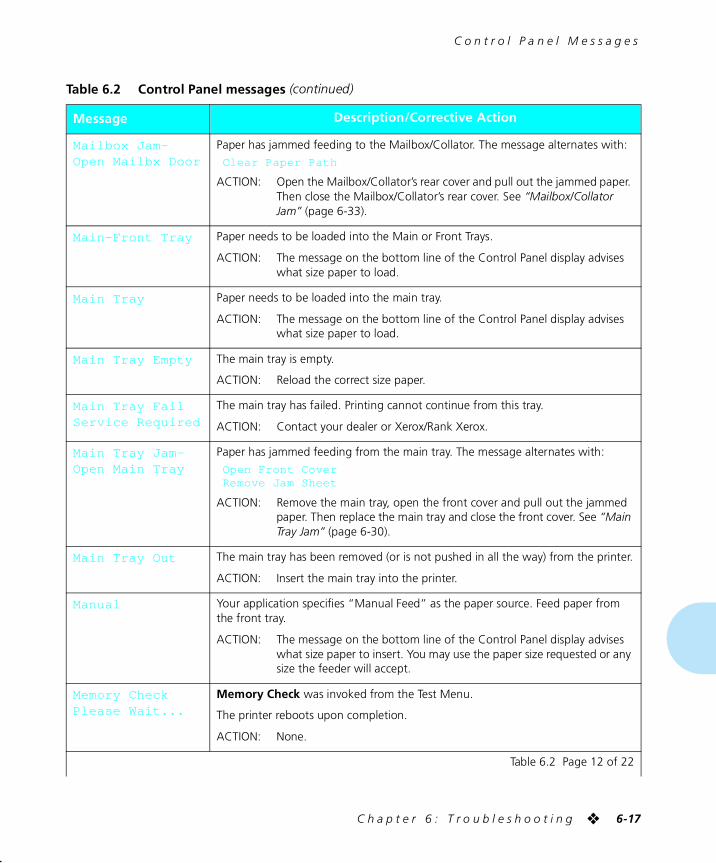
C o n t r o l P a n e l M e s s a g e s
C h a p t e r 6 : T r o u b l e s h o o t i n g ❖ 6-17
Mailbox Jam-Open Mailbx Door
Paper has jammed feeding to the Mailbox/Collator. The message alternates with:
Clear Paper Path
ACTION: Open the Mailbox/Collator’s rear cover and pull out the jammed paper. Then close the Mailbox/Collator’s rear cover. See “Mailbox/Collator Jam” (page 6-33).
Main-Front Tray Paper needs to be loaded into the Main or Front Trays.
ACTION: The message on the bottom line of the Control Panel display advises what size paper to load.
Main Tray Paper needs to be loaded into the main tray.
ACTION: The message on the bottom line of the Control Panel display advises what size paper to load.
Main Tray Empty The main tray is empty.
ACTION: Reload the correct size paper.
Main Tray FailService Required
The main tray has failed. Printing cannot continue from this tray.
ACTION: Contact your dealer or Xerox/Rank Xerox.
Main Tray Jam-Open Main Tray
Paper has jammed feeding from the main tray. The message alternates with:
Open Front CoverRemove Jam Sheet
ACTION: Remove the main tray, open the front cover and pull out the jammed paper. Then replace the main tray and close the front cover. See “Main Tray Jam” (page 6-30).
Main Tray Out The main tray has been removed (or is not pushed in all the way) from the printer.
ACTION: Insert the main tray into the printer.
Manual Your application specifies “Manual Feed” as the paper source. Feed paper from the front tray.
ACTION: The message on the bottom line of the Control Panel display advises what size paper to insert. You may use the paper size requested or any size the feeder will accept.
Memory CheckPlease Wait...
Memory Check was invoked from the Test Menu.
The printer reboots upon completion.
ACTION: None.
Table 6.2 Control Panel messages (continued)
Message Description/Corrective Action
Table 6.2 Page 12 of 22
chapter6.frm Page 17 Friday, July 11, 1997 8:19 PM

C o n t r o l P a n e l M e s s a g e s
6-18 ❖ D o c u P r i n t 4 5 1 7 / 4 5 1 7 m p U s e r G u i d e
Memory FailureService Required
The printer controller memory has failed; printing cannot resume.
ACTION: • Perform a Memory Check to see if you can locate the problem.
• Try powering OFF the printer then ON again.
If the problem persists, contact your dealer or Xerox/Rank Xerox.
Motor FailureService Required
The printer motor has failed. Printing cannot continue.
ACTION: Cycle the printer’s power. If the problem persists, contact your dealer or Xerox/Rank Xerox.
New Password>> XXXX
A new password is being enabled for a bin or the collator. An existing valid password has been entered and a new password is expected to be entered (where the XXXX is displayed.
ACTION: Enter a new 4-digit password using the numeric keypad. Be sure to memorize this new password, as it will be needed to open the bin or mailbox.
NV Memory FailService Required
Nonvolatile memory on the printer controller has failed; printing cannot resume.
ACTION: Contact your dealer or Xerox/Rank Xerox.
Offline _/_Press a key...
The printer is offline, not in menu mode, and without any fault conditions.
Offline does not mean the printer is disconnected from the computer. It means page formatting and printing are halted.
ACTION: To put the printer online, press Online .
ACTION: To select menus, press Menu .
ACTION: To reset the printer, press Reset .
Offset Jam-Open Rear Cover
Paper has jammed feeding to the OCT. The message alternates with:
Open Offset DoorClear Paper Path
ACTION: See “OCT Jam” (page 6-33).
Offset Tray FailService Required
The Offset Catch Tray (OCT) has failed. Printing to the OCT cannot continue. You can however, direct output to the standard output tray.
ACTION: Remove and reinstall the OCT as per the instructions in Appendix C: Installing and Removing Printer Options. If the problem persists, contact your dealer or Xerox/Rank Xerox.
Table 6.2 Control Panel messages (continued)
Message Description/Corrective Action
Table 6.2 Page 13 of 22
chapter6.frm Page 18 Friday, July 11, 1997 8:19 PM
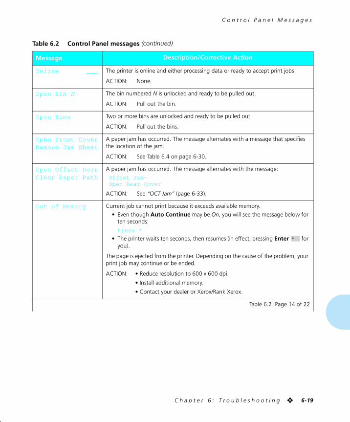
C o n t r o l P a n e l M e s s a g e s
C h a p t e r 6 : T r o u b l e s h o o t i n g ❖ 6-19
Online ___ The printer is online and either processing data or ready to accept print jobs.
ACTION: None.
Open Bin N The bin numbered N is unlocked and ready to be pulled out.
ACTION: Pull out the bin.
Open Bins Two or more bins are unlocked and ready to be pulled out.
ACTION: Pull out the bins.
Open Front CoverRemove Jam Sheet
A paper jam has occurred. The message alternates with a message that specifies the location of the jam.
ACTION: See Table 6.4 on page 6-30.
Open Offset DoorClear Paper Path
A paper jam has occurred. The message alternates with the message:
Offset Jam-Open Rear Cover
ACTION: See “OCT Jam” (page 6-33).
Out of Memory Current job cannot print because it exceeds available memory.
• Even though Auto Continue may be On, you will see the message below for ten seconds:
Press *
• The printer waits ten seconds, then resumes (in effect, pressing Enter for you).
The page is ejected from the printer. Depending on the cause of the problem, your print job may continue or be ended.
ACTION: • Reduce resolution to 600 x 600 dpi.
• Install additional memory.
• Contact your dealer or Xerox/Rank Xerox.
Table 6.2 Control Panel messages (continued)
Message Description/Corrective Action
Table 6.2 Page 14 of 22
chapter6.frm Page 19 Friday, July 11, 1997 8:19 PM
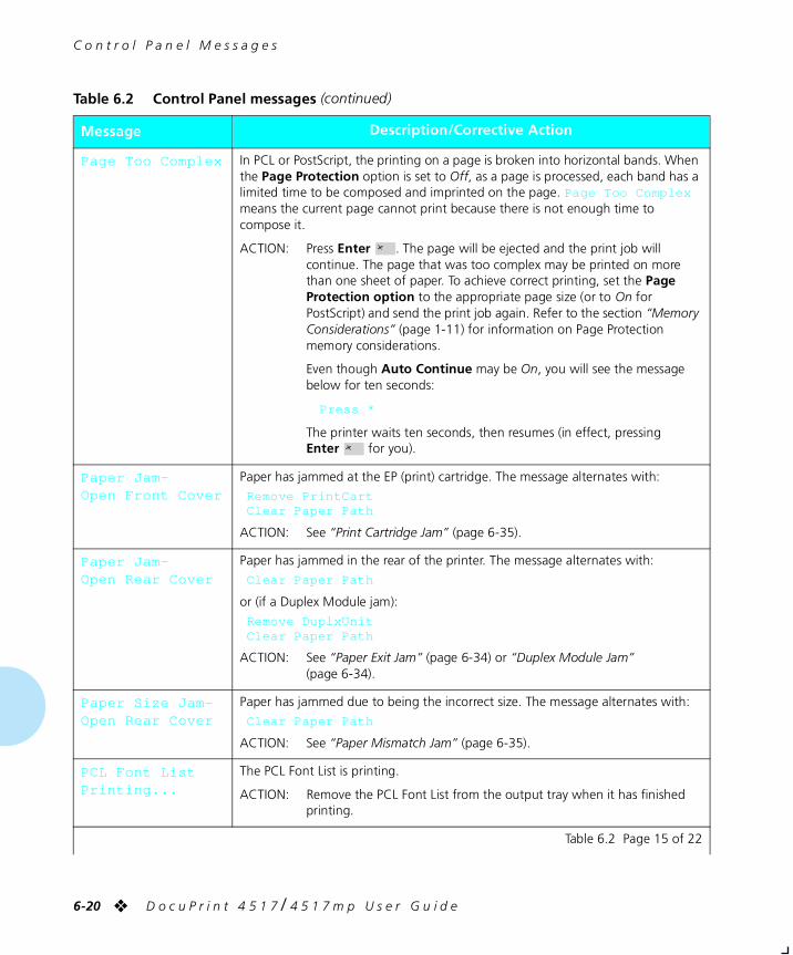
C o n t r o l P a n e l M e s s a g e s
6-20 ❖ D o c u P r i n t 4 5 1 7 / 4 5 1 7 m p U s e r G u i d e
Page Too Complex In PCL or PostScript, the printing on a page is broken into horizontal bands. When the Page Protection option is set to Off, as a page is processed, each band has a limited time to be composed and imprinted on the page. Page Too Complex means the current page cannot print because there is not enough time to compose it.
ACTION: Press Enter . The page will be ejected and the print job will continue. The page that was too complex may be printed on more than one sheet of paper. To achieve correct printing, set the Page Protection option to the appropriate page size (or to On for PostScript) and send the print job again. Refer to the section “Memory Considerations” (page 1-11) for information on Page Protection memory considerations.
Even though Auto Continue may be On, you will see the message below for ten seconds:
Press *
The printer waits ten seconds, then resumes (in effect, pressing Enter for you).
Paper Jam-Open Front Cover
Paper has jammed at the EP (print) cartridge. The message alternates with:
Remove PrintCartClear Paper Path
ACTION: See “Print Cartridge Jam” (page 6-35).
Paper Jam-Open Rear Cover
Paper has jammed in the rear of the printer. The message alternates with:
Clear Paper Path
or (if a Duplex Module jam):
Remove DuplxUnitClear Paper Path
ACTION: See “Paper Exit Jam” (page 6-34) or “Duplex Module Jam” (page 6-34).
Paper Size Jam-Open Rear Cover
Paper has jammed due to being the incorrect size. The message alternates with:
Clear Paper Path
ACTION: See “Paper Mismatch Jam” (page 6-35).
PCL Font ListPrinting...
The PCL Font List is printing.
ACTION: Remove the PCL Font List from the output tray when it has finished printing.
Table 6.2 Control Panel messages (continued)
Message Description/Corrective Action
Table 6.2 Page 15 of 22
chapter6.frm Page 20 Friday, July 11, 1997 8:19 PM
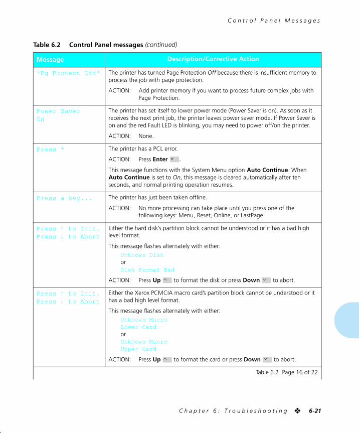
C o n t r o l P a n e l M e s s a g e s
C h a p t e r 6 : T r o u b l e s h o o t i n g ❖ 6-21
*Pg Protect Off* The printer has turned Page Protection Off because there is insufficient memory to process the job with page protection.
ACTION: Add printer memory if you want to process future complex jobs with Page Protection.
Power Saver On
The printer has set itself to lower power mode (Power Saver is on). As soon as it receives the next print job, the printer leaves power saver mode. If Power Saver is on and the red Fault LED is blinking, you may need to power off/on the printer.
ACTION: None.
Press * The printer has a PCL error.
ACTION: Press Enter .
This message functions with the System Menu option Auto Continue. When Auto Continue is set to On, this message is cleared automatically after ten seconds, and normal printing operation resumes.
Press a key... The printer has just been taken offline.
ACTION: No more processing can take place until you press one of the following keys: Menu, Reset, Online, or LastPage.
Press ↑ to Init.Press ↓ to Abort
Either the hard disk’s partition block cannot be understood or it has a bad high level format.
This message flashes alternately with either:
Unknown DiskorDisk Format Bad
ACTION: Press Up to format the disk or press Down to abort.
Press ↑ to Init.Press ↓ to Abort
Either the Xerox PCMCIA macro card’s partition block cannot be understood or it has a bad high level format.
This message flashes alternately with either:
Unknown MacroLower CardorUnknown MacroUpper Card
ACTION: Press Up to format the card or press Down to abort.
Table 6.2 Control Panel messages (continued)
Message Description/Corrective Action
Table 6.2 Page 16 of 22
chapter6.frm Page 21 Friday, July 11, 1997 8:19 PM
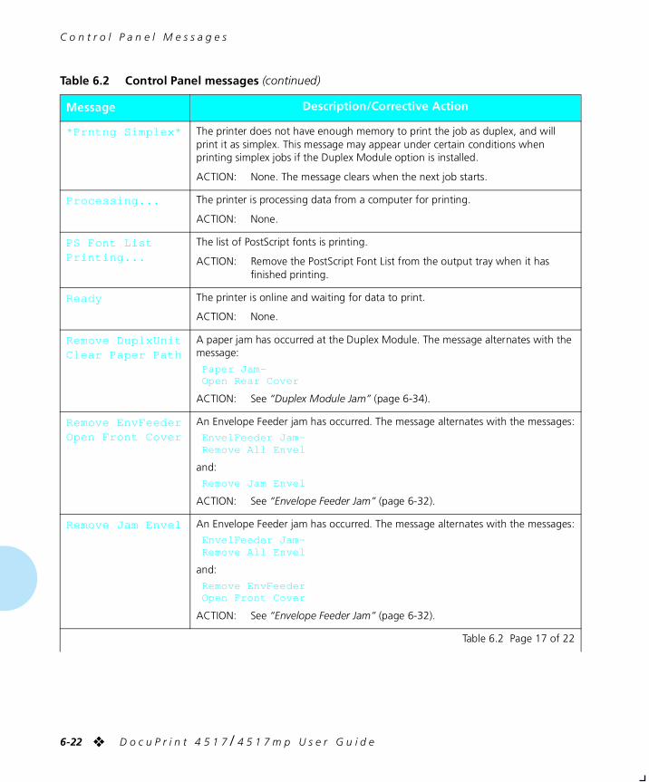
C o n t r o l P a n e l M e s s a g e s
6-22 ❖ D o c u P r i n t 4 5 1 7 / 4 5 1 7 m p U s e r G u i d e
*Prntng Simplex* The printer does not have enough memory to print the job as duplex, and will print it as simplex. This message may appear under certain conditions when printing simplex jobs if the Duplex Module option is installed.
ACTION: None. The message clears when the next job starts.
Processing... The printer is processing data from a computer for printing.
ACTION: None.
PS Font ListPrinting...
The list of PostScript fonts is printing.
ACTION: Remove the PostScript Font List from the output tray when it has finished printing.
Ready The printer is online and waiting for data to print.
ACTION: None.
Remove DuplxUnitClear Paper Path
A paper jam has occurred at the Duplex Module. The message alternates with the message:
Paper Jam-Open Rear Cover
ACTION: See “Duplex Module Jam” (page 6-34).
Remove EnvFeederOpen Front Cover
An Envelope Feeder jam has occurred. The message alternates with the messages:
EnvelFeeder Jam-Remove All Envel
and:
Remove Jam Envel
ACTION: See “Envelope Feeder Jam” (page 6-32).
Remove Jam Envel An Envelope Feeder jam has occurred. The message alternates with the messages:
EnvelFeeder Jam-Remove All Envel
and:
Remove EnvFeederOpen Front Cover
ACTION: See “Envelope Feeder Jam” (page 6-32).
Table 6.2 Control Panel messages (continued)
Message Description/Corrective Action
Table 6.2 Page 17 of 22
chapter6.frm Page 22 Friday, July 11, 1997 8:19 PM
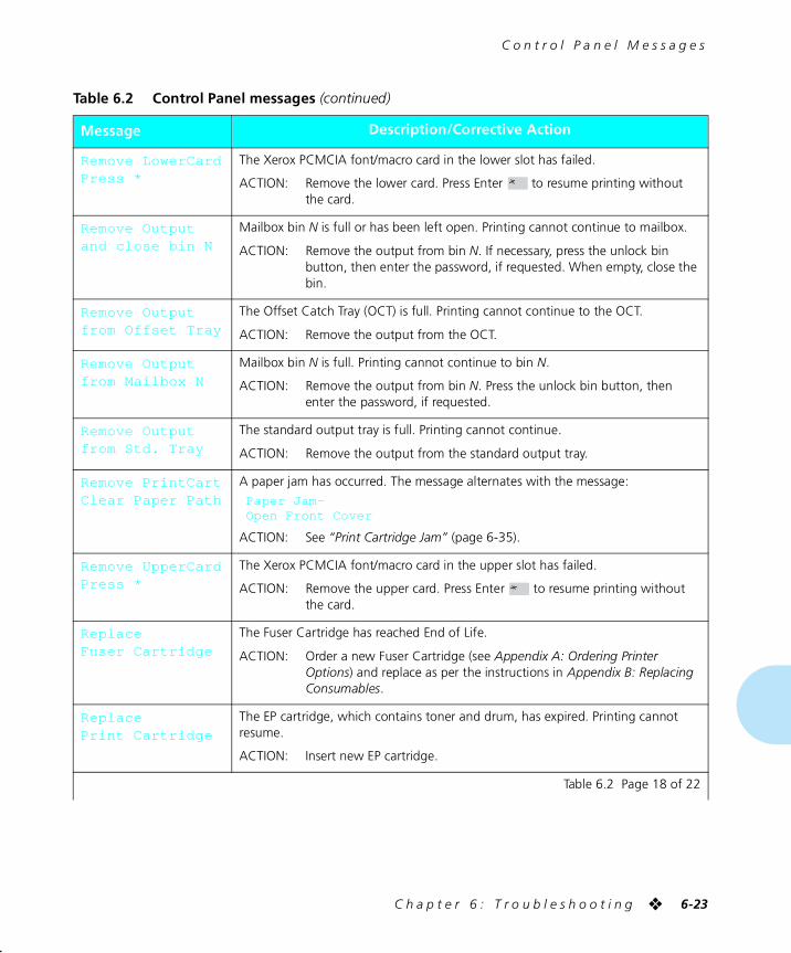
C o n t r o l P a n e l M e s s a g e s
C h a p t e r 6 : T r o u b l e s h o o t i n g ❖ 6-23
Remove LowerCardPress *
The Xerox PCMCIA font/macro card in the lower slot has failed.
ACTION: Remove the lower card. Press Enter to resume printing without the card.
Remove Outputand close bin N
Mailbox bin N is full or has been left open. Printing cannot continue to mailbox.
ACTION: Remove the output from bin N. If necessary, press the unlock bin button, then enter the password, if requested. When empty, close the bin.
Remove Outputfrom Offset Tray
The Offset Catch Tray (OCT) is full. Printing cannot continue to the OCT.
ACTION: Remove the output from the OCT.
Remove Outputfrom Mailbox N
Mailbox bin N is full. Printing cannot continue to bin N.
ACTION: Remove the output from bin N. Press the unlock bin button, then enter the password, if requested.
Remove Outputfrom Std. Tray
The standard output tray is full. Printing cannot continue.
ACTION: Remove the output from the standard output tray.
Remove PrintCartClear Paper Path
A paper jam has occurred. The message alternates with the message:
Paper Jam-Open Front Cover
ACTION: See “Print Cartridge Jam” (page 6-35).
Remove UpperCardPress *
The Xerox PCMCIA font/macro card in the upper slot has failed.
ACTION: Remove the upper card. Press Enter to resume printing without the card.
ReplaceFuser Cartridge
The Fuser Cartridge has reached End of Life.
ACTION: Order a new Fuser Cartridge (see Appendix A: Ordering Printer Options) and replace as per the instructions in Appendix B: Replacing Consumables.
ReplacePrint Cartridge
The EP cartridge, which contains toner and drum, has expired. Printing cannot resume.
ACTION: Insert new EP cartridge.
Table 6.2 Control Panel messages (continued)
Message Description/Corrective Action
Table 6.2 Page 18 of 22
chapter6.frm Page 23 Friday, July 11, 1997 8:20 PM
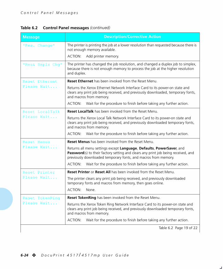
C o n t r o l P a n e l M e s s a g e s
6-24 ❖ D o c u P r i n t 4 5 1 7 / 4 5 1 7 m p U s e r G u i d e
*Res. Change* The printer is printing the job at a lower resolution than requested because there is not enough memory available.
ACTION: Add printer memory.
*Res& Smplx Chg* The printer has changed the job resolution, and changed a duplex job to simplex, because there is not enough memory to process the job at the higher resolution and duplex.
Reset EthernetPlease Wait...
Reset Ethernet has been invoked from the Reset Menu.
Returns the Xerox Ethernet Network Interface Card to its power-on state and clears any print job being received, and previously downloaded, temporary fonts, and macros from memory.
ACTION: Wait for the procedure to finish before taking any further action.
Reset LocalTalkPlease Wait...
Reset LocalTalk has been invoked from the Reset Menu.
Returns the Xerox Local Talk Network Interface Card to its power-on state and clears any print job being received, and previously downloaded temporary fonts, and macros from memory.
ACTION: Wait for the procedure to finish before taking any further action.
Reset MenusPlease Wait...
Reset Menus has been invoked from the Reset Menu.
Returns all menu settings except Language, Defaults, PowerSaver, and Password(s) to their factory setting and clears any print job being received, and previously downloaded temporary fonts, and macros from memory.
ACTION: Wait for the procedure to finish before taking any further action.
Reset PrinterPlease Wait...
Reset Printer or Reset All has been invoked from the Reset Menu.
The printer clears any print job being received, and previously downloaded temporary fonts and macros from memory, then goes online.
ACTION: None.
Reset TokenRingPlease Wait...
Reset TokenRing has been invoked from the Reset Menu.
Returns the Xerox Token Ring Network Interface Card to its power-on state and clears any print job being received, and previously downloaded temporary fonts, and macros from memory.
ACTION: Wait for the procedure to finish before taking any further action.
Table 6.2 Control Panel messages (continued)
Message Description/Corrective Action
Table 6.2 Page 19 of 22
chapter6.frm Page 24 Friday, July 11, 1997 8:20 PM
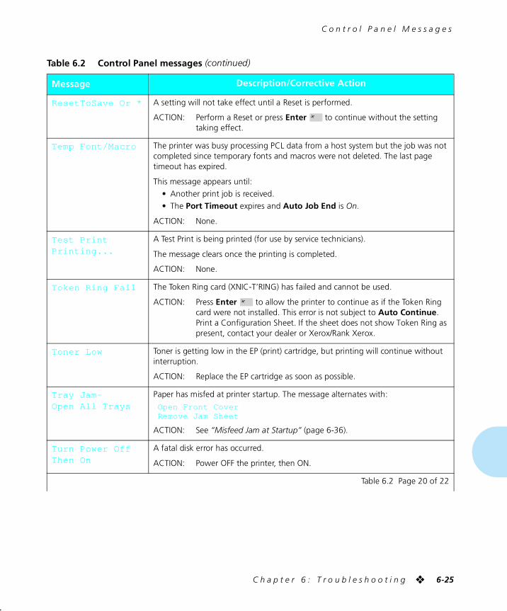
C o n t r o l P a n e l M e s s a g e s
C h a p t e r 6 : T r o u b l e s h o o t i n g ❖ 6-25
ResetToSave Or * A setting will not take effect until a Reset is performed.
ACTION: Perform a Reset or press Enter to continue without the setting taking effect.
Temp Font/Macro The printer was busy processing PCL data from a host system but the job was not completed since temporary fonts and macros were not deleted. The last page timeout has expired.
This message appears until:
• Another print job is received.
• The Port Timeout expires and Auto Job End is On.
ACTION: None.
Test PrintPrinting...
A Test Print is being printed (for use by service technicians).
The message clears once the printing is completed.
ACTION: None.
Token Ring Fail The Token Ring card (XNIC-T’RING) has failed and cannot be used.
ACTION: Press Enter to allow the printer to continue as if the Token Ring card were not installed. This error is not subject to Auto Continue. Print a Configuration Sheet. If the sheet does not show Token Ring as present, contact your dealer or Xerox/Rank Xerox.
Toner Low Toner is getting low in the EP (print) cartridge, but printing will continue without interruption.
ACTION: Replace the EP cartridge as soon as possible.
Tray Jam-Open All Trays
Paper has misfed at printer startup. The message alternates with:
Open Front CoverRemove Jam Sheet
ACTION: See “Misfeed Jam at Startup” (page 6-36).
Turn Power OffThen On
A fatal disk error has occurred.
ACTION: Power OFF the printer, then ON.
Table 6.2 Control Panel messages (continued)
Message Description/Corrective Action
Table 6.2 Page 20 of 22
chapter6.frm Page 25 Friday, July 11, 1997 8:20 PM
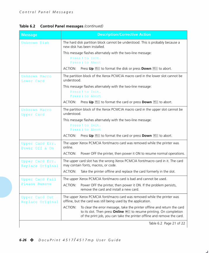
C o n t r o l P a n e l M e s s a g e s
6-26 ❖ D o c u P r i n t 4 5 1 7 / 4 5 1 7 m p U s e r G u i d e
Unknown Disk The hard disk partition block cannot be understood. This is probably because a new disk has been installed.
This message flashes alternately with the two-line message:
Press ↑ to Init.Press ↓ to Abort
ACTION: Press Up to format the disk or press Down to abort.
Unknown MacroLower Card
The partition block of the Xerox PCMCIA macro card in the lower slot cannot be understood.
This message flashes alternately with the two-line message:
Press ↑ to Init.Press ↓ to Abort
ACTION: Press Up to format the card or press Down to abort.
Unknown MacroUpper Card
The partition block of the Xerox PCMCIA macro card in the upper slot cannot be understood.
This message flashes alternately with the two-line message:
Press ↑ to Init.Press ↓ to Abort
ACTION: Press Up to format the card or press Down to abort.
Upper Card Err.Power Off & On
The upper Xerox PCMCIA font/macro card was removed while the printer was online.
ACTION: Power OFF the printer, then power it ON to resume normal operations.
Upper Card Err.Replace Original
The upper card slot has the wrong Xerox PCMCIA font/macro card in it. The card may contain fonts, macros, or code.
ACTION: Take the printer offline and replace the card formerly in the slot.
Upper Card FailPlease Remove
The upper Xerox PCMCIA font/macro card is bad and cannot be used.
ACTION: Power OFF the printer, then power it ON. If the problem persists, remove the card and install a new card.
Upper Card OutReplace Original
The upper Xerox PCMCIA font/macro card was removed while the printer was offline, but the card was still being used by the application.
ACTION: To clear the error message, take the printer offline and return the card to its slot. Then press Online to resume printing. On completion of the print job, you can take the printer offline and remove the card.
Table 6.2 Control Panel messages (continued)
Message Description/Corrective Action
Table 6.2 Page 21 of 22
chapter6.frm Page 26 Friday, July 11, 1997 8:20 PM
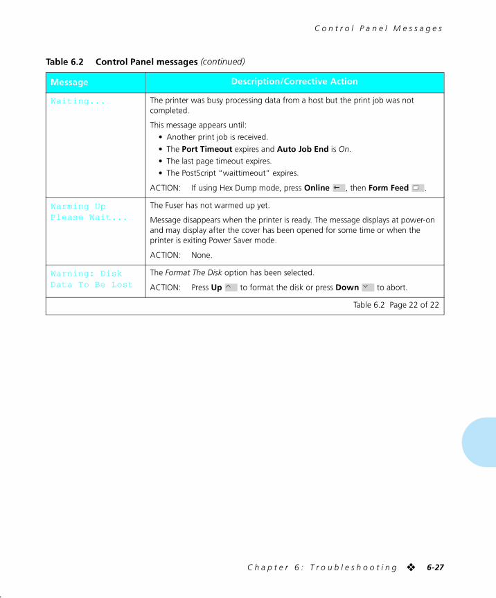
C o n t r o l P a n e l M e s s a g e s
C h a p t e r 6 : T r o u b l e s h o o t i n g ❖ 6-27
Waiting... The printer was busy processing data from a host but the print job was not completed.
This message appears until:
• Another print job is received.
• The Port Timeout expires and Auto Job End is On.
• The last page timeout expires.
• The PostScript “waittimeout” expires.
ACTION: If using Hex Dump mode, press Online , then Form Feed .
Warming UpPlease Wait...
The Fuser has not warmed up yet.
Message disappears when the printer is ready. The message displays at power-on and may display after the cover has been opened for some time or when the printer is exiting Power Saver mode.
ACTION: None.
Warning: DiskData To Be Lost
The Format The Disk option has been selected.
ACTION: Press Up to format the disk or press Down to abort.
Table 6.2 Control Panel messages (continued)
Message Description/Corrective Action
Table 6.2 Page 22 of 22
chapter6.frm Page 27 Friday, July 11, 1997 8:20 PM
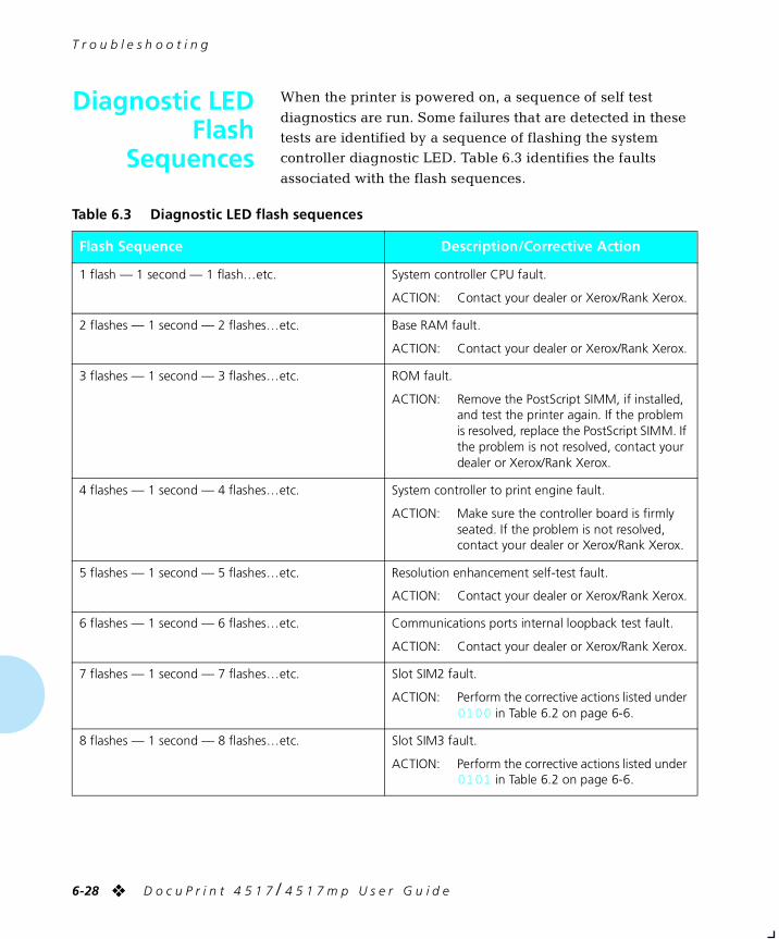
T r o u b l e s h o o t i n g
6-28 ❖ D o c u P r i n t 4 5 1 7 / 4 5 1 7 m p U s e r G u i d e
Diagnostic LEDFlash
Sequences
When the printer is powered on, a sequence of self test
diagnostics are run. Some failures that are detected in these tests are identified by a sequence of flashing the system controller diagnostic LED. Table 6.3 identifies the faults
associated with the flash sequences.
Table 6.3 Diagnostic LED flash sequences
Flash Sequence Description/Corrective Action
1 flash — 1 second — 1 flash…etc. System controller CPU fault.
ACTION: Contact your dealer or Xerox/Rank Xerox.
2 flashes — 1 second — 2 flashes…etc. Base RAM fault.
ACTION: Contact your dealer or Xerox/Rank Xerox.
3 flashes — 1 second — 3 flashes…etc. ROM fault.
ACTION: Remove the PostScript SIMM, if installed, and test the printer again. If the problem is resolved, replace the PostScript SIMM. If the problem is not resolved, contact your dealer or Xerox/Rank Xerox.
4 flashes — 1 second — 4 flashes…etc. System controller to print engine fault.
ACTION: Make sure the controller board is firmly seated. If the problem is not resolved, contact your dealer or Xerox/Rank Xerox.
5 flashes — 1 second — 5 flashes…etc. Resolution enhancement self-test fault.
ACTION: Contact your dealer or Xerox/Rank Xerox.
6 flashes — 1 second — 6 flashes…etc. Communications ports internal loopback test fault.
ACTION: Contact your dealer or Xerox/Rank Xerox.
7 flashes — 1 second — 7 flashes…etc. Slot SIM2 fault.
ACTION: Perform the corrective actions listed under 0100 in Table 6.2 on page 6-6.
8 flashes — 1 second — 8 flashes…etc. Slot SIM3 fault.
ACTION: Perform the corrective actions listed under 0101 in Table 6.2 on page 6-6.
chapter6.frm Page 28 Friday, July 11, 1997 8:20 PM
T r o u b l e s h o o t i n g
C h a p t e r 6 : T r o u b l e s h o o t i n g ❖ 6-29
Paper Jams Your printer has been designed to provide reliable, trouble-
free operation. Nonetheless, you may experience an occasional paper jam.
When the printer detects a misfeed or a paper jam, the
printing process is halted, and a Control Panel message is displayed.
After the paper jam has been cleared, the printer will resume
operation to complete the print job. Set the Jam Recovery option to On to guarantee that pages in the print engine when the jam occurs will be reprinted. Refer to the section
“Memory Considerations” (page 1-11).
What Causes aPaper Jam?
Paper jams occur most often when:
• The throughput paper stock does not meet specification. See Chapter 2: Paper Handling.
• The paper stock is in poor condition.
• The paper stock has been improperly loaded into the
paper trays.
• The printer needs cleaning.
• Printer parts are worn and need to be replaced.
ClearingPaper Jams
Table 6.4 on page 6-30 lists the types of paper jams that may occur. If you see a Control Panel message that indicates a paper jam, find the message in the left-hand column and
perform the accompanying steps to clear the paper jam.
Caution
Be careful not to touch any of the components inside the printer when removing jammed paper. They may be very hot.
chapter6.frm Page 29 Friday, July 11, 1997 8:20 PM
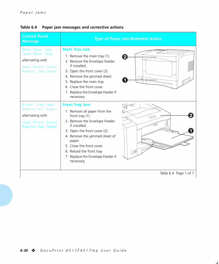
P a p e r J a m s
6-30 ❖ D o c u P r i n t 4 5 1 7 / 4 5 1 7 m p U s e r G u i d e
Table 6.4 Paper jam messages and corrective actions
Control Panel Message
Type of Paper Jam/Remedial Action
Main Tray Jam-Open Main Tray
alternating with
Open Front CoverRemove Jam Sheet
Main Tray Jam
1. Remove the main tray (1).
2. Remove the Envelope Feeder if installed.
3. Open the front cover (2).
4. Remove the jammed sheet.
5. Replace the main tray.
6. Close the front cover.
7. Replace the Envelope Feeder if necessary.
Front Tray Jam-Remove All Paper
alternating with
Open Front CoverRemove Jam Sheet
Front Tray Jam
1. Remove all paper from the front tray (1).
2. Remove the Envelope Feeder if installed.
3. Open the front cover (2).
4. Remove the jammed sheet of paper.
5. Close the front cover.
6. Reload the front tray.
7. Replace the Envelope Feeder if necessary.
Table 6.4 Page 1 of 7
chapter6.frm Page 30 Friday, July 11, 1997 8:20 PM
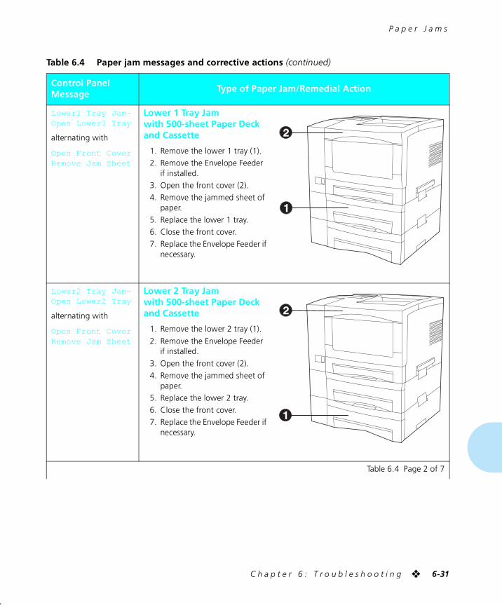
P a p e r J a m s
C h a p t e r 6 : T r o u b l e s h o o t i n g ❖ 6-31
Lower1 Tray Jam-Open Lower1 Tray
alternating with
Open Front CoverRemove Jam Sheet
Lower 1 Tray Jamwith 500-sheet Paper Deck and Cassette
1. Remove the lower 1 tray (1).
2. Remove the Envelope Feeder if installed.
3. Open the front cover (2).
4. Remove the jammed sheet of paper.
5. Replace the lower 1 tray.
6. Close the front cover.
7. Replace the Envelope Feeder if necessary.
Lower2 Tray Jam-Open Lower2 Tray
alternating with
Open Front CoverRemove Jam Sheet
Lower 2 Tray Jamwith 500-sheet Paper Deck and Cassette
1. Remove the lower 2 tray (1).
2. Remove the Envelope Feeder if installed.
3. Open the front cover (2).
4. Remove the jammed sheet of paper.
5. Replace the lower 2 tray.
6. Close the front cover.
7. Replace the Envelope Feeder if necessary.
Table 6.4 Paper jam messages and corrective actions (continued)
Control Panel Message
Type of Paper Jam/Remedial Action
Table 6.4 Page 2 of 7
chapter6.frm Page 31 Friday, July 11, 1997 8:20 PM
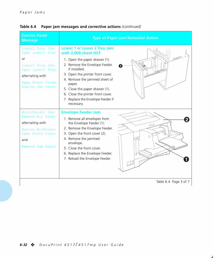
P a p e r J a m s
6-32 ❖ D o c u P r i n t 4 5 1 7 / 4 5 1 7 m p U s e r G u i d e
Lower1 Tray Jam-Open Lower1 Tray
or
Lower2 Tray Jam-Open Lower2 Tray
alternating with
Open Front CoverRemove Jam Sheet
Lower 1 or Lower 2 Tray Jam with 2,000-sheet HCF
1. Open the paper drawer (1).
2. Remove the Envelope Feeder if installed.
3. Open the printer front cover.
4. Remove the jammed sheet of paper.
5. Close the paper drawer (1).
6. Close the printer front cover.
7. Replace the Envelope Feeder if necessary.
EnvelFeeder Jam-Remove All Envel
alternating with
Remove EnvFeederOpen Front Cover
and
Remove Jam Envel
Envelope Feeder Jam
1. Remove all envelopes from the Envelope Feeder (1).
2. Remove the Envelope Feeder.
3. Open the front cover (2).
4. Remove the jammed envelope.
5. Close the front cover.
6. Replace the Envelope Feeder.
7. Reload the Envelope Feeder.
Table 6.4 Paper jam messages and corrective actions (continued)
Control Panel Message
Type of Paper Jam/Remedial Action
Table 6.4 Page 3 of 7
chapter6.frm Page 32 Friday, July 11, 1997 8:20 PM
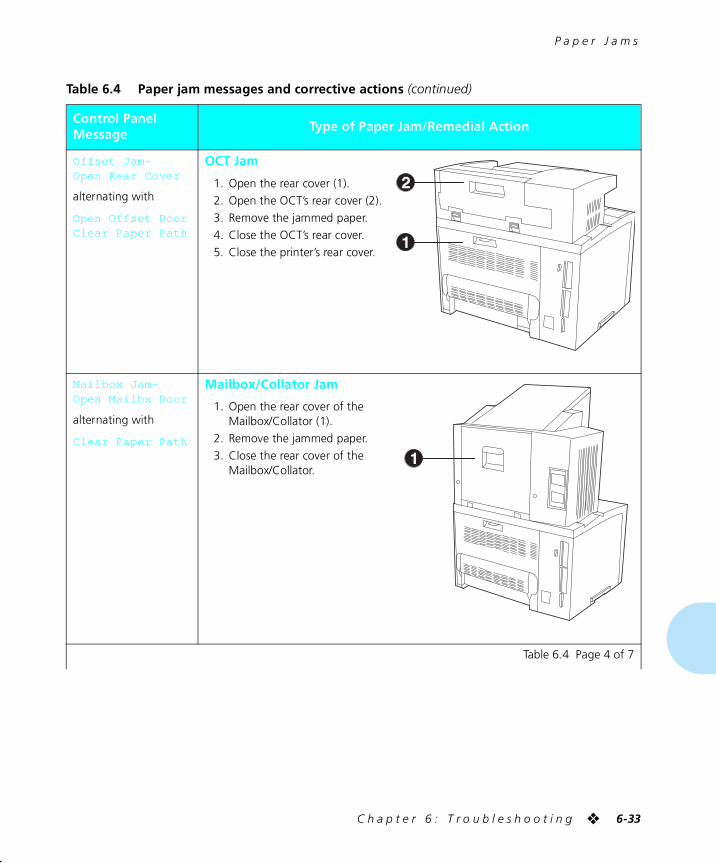
P a p e r J a m s
C h a p t e r 6 : T r o u b l e s h o o t i n g ❖ 6-33
Offset Jam-Open Rear Cover
alternating with
Open Offset DoorClear Paper Path
OCT Jam
1. Open the rear cover (1).
2. Open the OCT’s rear cover (2).
3. Remove the jammed paper.
4. Close the OCT’s rear cover.
5. Close the printer’s rear cover.
Mailbox Jam-Open Mailbx Door
alternating with
Clear Paper Path
Mailbox/Collator Jam
1. Open the rear cover of the Mailbox/Collator (1).
2. Remove the jammed paper.
3. Close the rear cover of the Mailbox/Collator.
Table 6.4 Paper jam messages and corrective actions (continued)
Control Panel Message
Type of Paper Jam/Remedial Action
Table 6.4 Page 4 of 7
chapter6.frm Page 33 Friday, July 11, 1997 8:20 PM
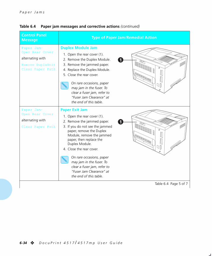
P a p e r J a m s
6-34 ❖ D o c u P r i n t 4 5 1 7 / 4 5 1 7 m p U s e r G u i d e
Paper Jam-Open Rear Cover
alternating with
Remove DuplxUnitClear Paper Path
Duplex Module Jam
1. Open the rear cover (1).
2. Remove the Duplex Module.
3. Remove the jammed paper.
4. Replace the Duplex Module.
5. Close the rear cover.
On rare occasions, paper may jam in the fuser. To clear a fuser jam, refer to “Fuser Jam Clearance” at the end of this table.
Paper Jam-Open Rear Cover
alternating with
Clear Paper Path
Paper Exit Jam
1. Open the rear cover (1).
2. Remove the jammed paper.
3. If you do not see the jammed paper, remove the Duplex Module, remove the jammed paper, then replace the Duplex Module.
4. Close the rear cover.
On rare occasions, paper may jam in the fuser. To clear a fuser jam, refer to “Fuser Jam Clearance” at the end of this table.
Table 6.4 Paper jam messages and corrective actions (continued)
Control Panel Message
Type of Paper Jam/Remedial Action
Table 6.4 Page 5 of 7
chapter6.frm Page 34 Friday, July 11, 1997 8:20 PM
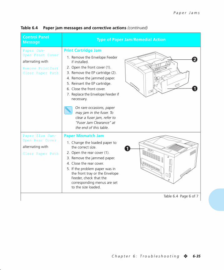
P a p e r J a m s
C h a p t e r 6 : T r o u b l e s h o o t i n g ❖ 6-35
Paper Jam-Open Front Cover
alternating with
Remove PrintCartClear Paper Path
Print Cartridge Jam
1. Remove the Envelope Feeder if installed.
2. Open the front cover (1).
3. Remove the EP cartridge (2).
4. Remove the jammed paper.
5. Reinsert the EP cartridge.
6. Close the front cover.
7. Replace the Envelope Feeder if necessary.
On rare occasions, paper may jam in the fuser. To clear a fuser jam, refer to “Fuser Jam Clearance” at the end of this table.
Paper Size Jam-Open Rear Cover
alternating with
Clear Paper Path
Paper Mismatch Jam
1. Change the loaded paper to the correct size.
2. Open the rear cover (1).
3. Remove the jammed paper.
4. Close the rear cover.
5. If the problem paper was in the front tray or the Envelope Feeder, check that the corresponding menus are set to the size loaded.
Table 6.4 Paper jam messages and corrective actions (continued)
Control Panel Message
Type of Paper Jam/Remedial Action
Table 6.4 Page 6 of 7
chapter6.frm Page 35 Friday, July 11, 1997 8:20 PM
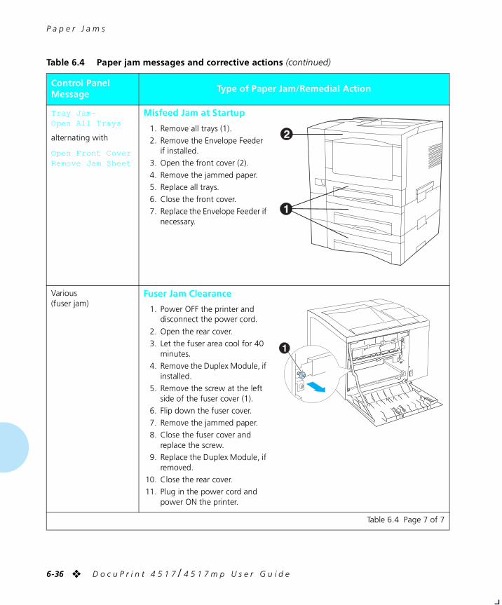
P a p e r J a m s
6-36 ❖ D o c u P r i n t 4 5 1 7 / 4 5 1 7 m p U s e r G u i d e
Tray Jam-Open All Trays
alternating with
Open Front CoverRemove Jam Sheet
Misfeed Jam at Startup
1. Remove all trays (1).
2. Remove the Envelope Feeder if installed.
3. Open the front cover (2).
4. Remove the jammed paper.
5. Replace all trays.
6. Close the front cover.
7. Replace the Envelope Feeder if necessary.
Various (fuser jam)
Fuser Jam Clearance
1. Power OFF the printer and disconnect the power cord.
2. Open the rear cover.
3. Let the fuser area cool for 40 minutes.
4. Remove the Duplex Module, if installed.
5. Remove the screw at the left side of the fuser cover (1).
6. Flip down the fuser cover.
7. Remove the jammed paper.
8. Close the fuser cover and replace the screw.
9. Replace the Duplex Module, if removed.
10. Close the rear cover.
11. Plug in the power cord and power ON the printer.
Table 6.4 Paper jam messages and corrective actions (continued)
Control Panel Message
Type of Paper Jam/Remedial Action
Table 6.4 Page 7 of 7
chapter6.frm Page 36 Friday, July 11, 1997 8:20 PM
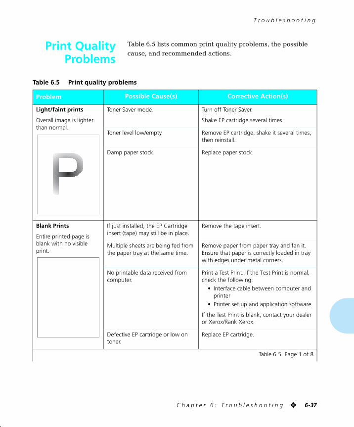
T r o u b l e s h o o t i n g
C h a p t e r 6 : T r o u b l e s h o o t i n g ❖ 6-37
Print QualityProblems
Table 6.5 lists common print quality problems, the possible
cause, and recommended actions.
Table 6.5 Print quality problems
Problem Possible Cause(s) Corrective Action(s)
Light/faint prints
Overall image is lighter than normal.
Toner Saver mode. Turn off Toner Saver.
Shake EP cartridge several times.
Toner level low/empty. Remove EP cartridge, shake it several times, then reinstall.
Damp paper stock. Replace paper stock.
Blank Prints
Entire printed page is blank with no visible print.
If just installed, the EP Cartridge insert (tape) may still be in place.
Remove the tape insert.
Multiple sheets are being fed from the paper tray at the same time.
Remove paper from paper tray and fan it. Ensure that paper is correctly loaded in tray with edges under metal corners.
No printable data received from computer.
Print a Test Print. If the Test Print is normal, check the following:
• Interface cable between computer and printer
• Printer set up and application software
If the Test Print is blank, contact your dealer or Xerox/Rank Xerox.
Defective EP cartridge or low on toner.
Replace EP cartridge.
Table 6.5 Page 1 of 8
chapter6.frm Page 37 Friday, July 11, 1997 8:20 PM
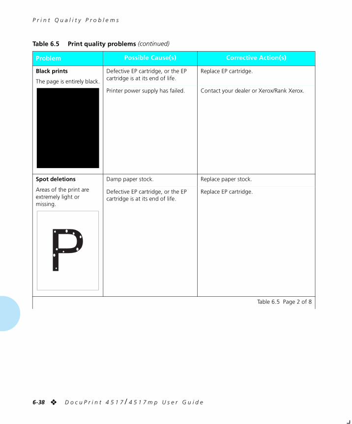
P r i n t Q u a l i t y P r o b l e m s
6-38 ❖ D o c u P r i n t 4 5 1 7 / 4 5 1 7 m p U s e r G u i d e
Black prints
The page is entirely black.
Defective EP cartridge, or the EP cartridge is at its end of life.
Replace EP cartridge.
Printer power supply has failed. Contact your dealer or Xerox/Rank Xerox.
Spot deletions
Areas of the print are extremely light or missing.
Damp paper stock. Replace paper stock.
Defective EP cartridge, or the EP cartridge is at its end of life.
Replace EP cartridge.
Table 6.5 Print quality problems (continued)
Problem Possible Cause(s) Corrective Action(s)
Table 6.5 Page 2 of 8
chapter6.frm Page 38 Friday, July 11, 1997 8:20 PM
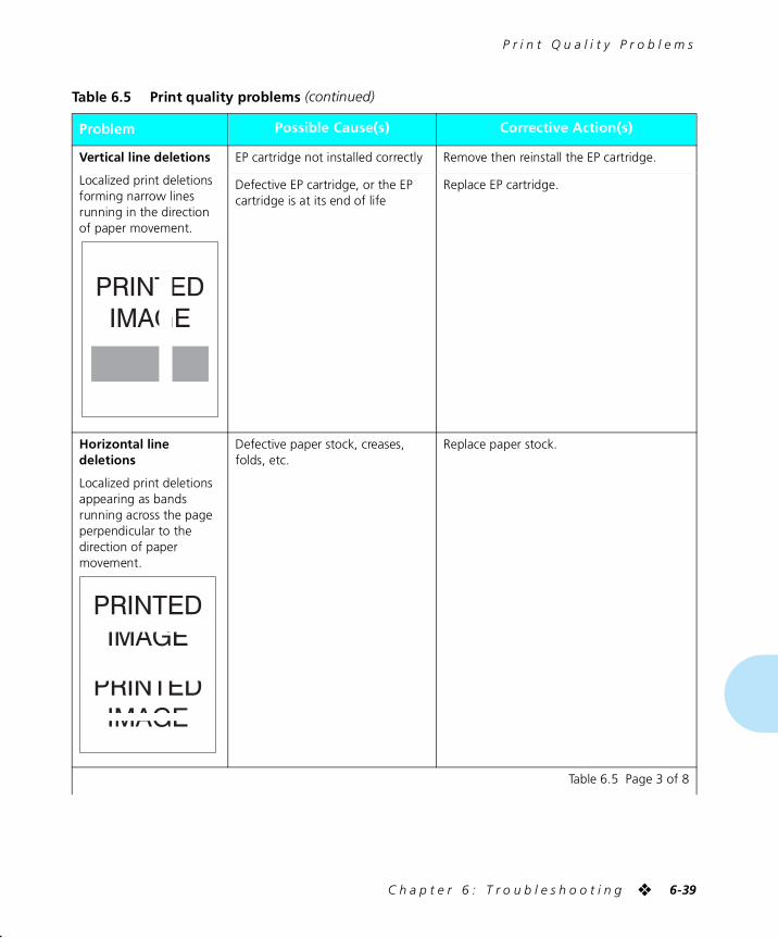
P r i n t Q u a l i t y P r o b l e m s
C h a p t e r 6 : T r o u b l e s h o o t i n g ❖ 6-39
Vertical line deletions
Localized print deletions forming narrow lines running in the direction of paper movement.
EP cartridge not installed correctly Remove then reinstall the EP cartridge.
Defective EP cartridge, or the EP cartridge is at its end of life
Replace EP cartridge.
Horizontal line deletions
Localized print deletions appearing as bands running across the page perpendicular to the direction of paper movement.
Defective paper stock, creases, folds, etc.
Replace paper stock.
Table 6.5 Print quality problems (continued)
Problem Possible Cause(s) Corrective Action(s)
Table 6.5 Page 3 of 8
chapter6.frm Page 39 Friday, July 11, 1997 8:20 PM
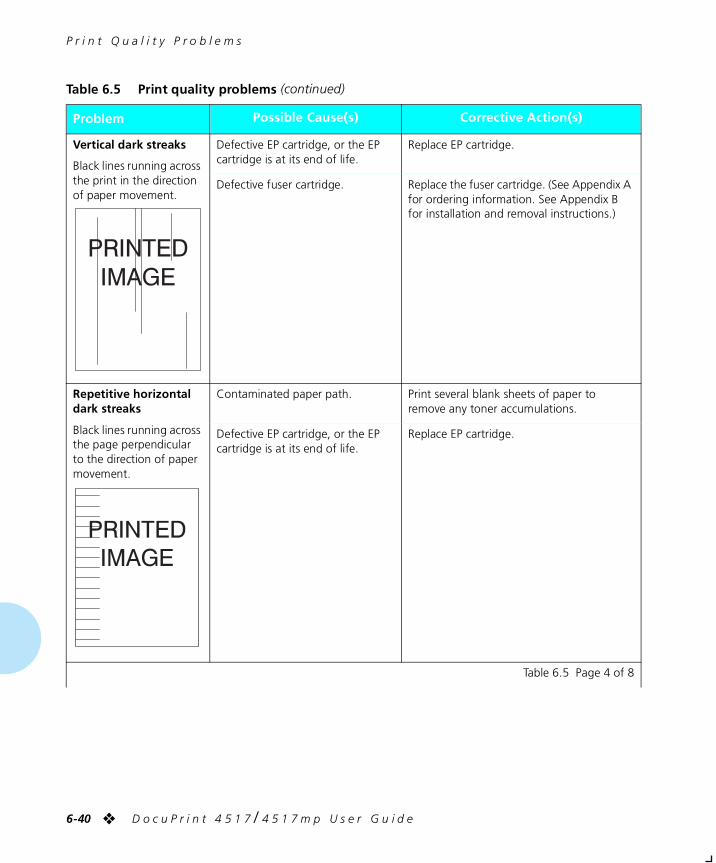
P r i n t Q u a l i t y P r o b l e m s
6-40 ❖ D o c u P r i n t 4 5 1 7 / 4 5 1 7 m p U s e r G u i d e
Vertical dark streaks
Black lines running across the print in the direction of paper movement.
Defective EP cartridge, or the EP cartridge is at its end of life.
Replace EP cartridge.
Defective fuser cartridge. Replace the fuser cartridge. (See Appendix A for ordering information. See Appendix B for installation and removal instructions.)
Repetitive horizontal dark streaks
Black lines running across the page perpendicular to the direction of paper movement.
Contaminated paper path. Print several blank sheets of paper to remove any toner accumulations.
Defective EP cartridge, or the EP cartridge is at its end of life.
Replace EP cartridge.
Table 6.5 Print quality problems (continued)
Problem Possible Cause(s) Corrective Action(s)
Table 6.5 Page 4 of 8
chapter6.frm Page 40 Friday, July 11, 1997 8:20 PM
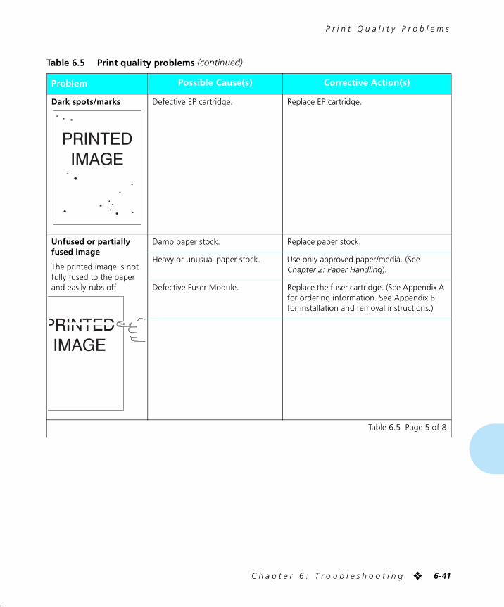
P r i n t Q u a l i t y P r o b l e m s
C h a p t e r 6 : T r o u b l e s h o o t i n g ❖ 6-41
Dark spots/marks Defective EP cartridge. Replace EP cartridge.
Unfused or partially fused image
The printed image is not fully fused to the paper and easily rubs off.
Damp paper stock. Replace paper stock.
Heavy or unusual paper stock. Use only approved paper/media. (See Chapter 2: Paper Handling).
Defective Fuser Module. Replace the fuser cartridge. (See Appendix A for ordering information. See Appendix B for installation and removal instructions.)
Table 6.5 Print quality problems (continued)
Problem Possible Cause(s) Corrective Action(s)
Table 6.5 Page 5 of 8
chapter6.frm Page 41 Friday, July 11, 1997 8:20 PM
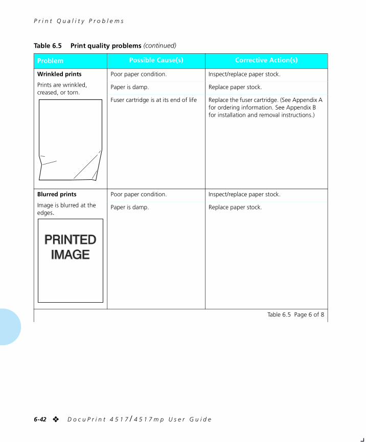
P r i n t Q u a l i t y P r o b l e m s
6-42 ❖ D o c u P r i n t 4 5 1 7 / 4 5 1 7 m p U s e r G u i d e
Wrinkled prints
Prints are wrinkled, creased, or torn.
Poor paper condition. Inspect/replace paper stock.
Paper is damp. Replace paper stock.
Fuser cartridge is at its end of life Replace the fuser cartridge. (See Appendix A for ordering information. See Appendix B for installation and removal instructions.)
Blurred prints
Image is blurred at the edges.
Poor paper condition. Inspect/replace paper stock.
Paper is damp. Replace paper stock.
Table 6.5 Print quality problems (continued)
Problem Possible Cause(s) Corrective Action(s)
Table 6.5 Page 6 of 8
chapter6.frm Page 42 Friday, July 11, 1997 8:20 PM
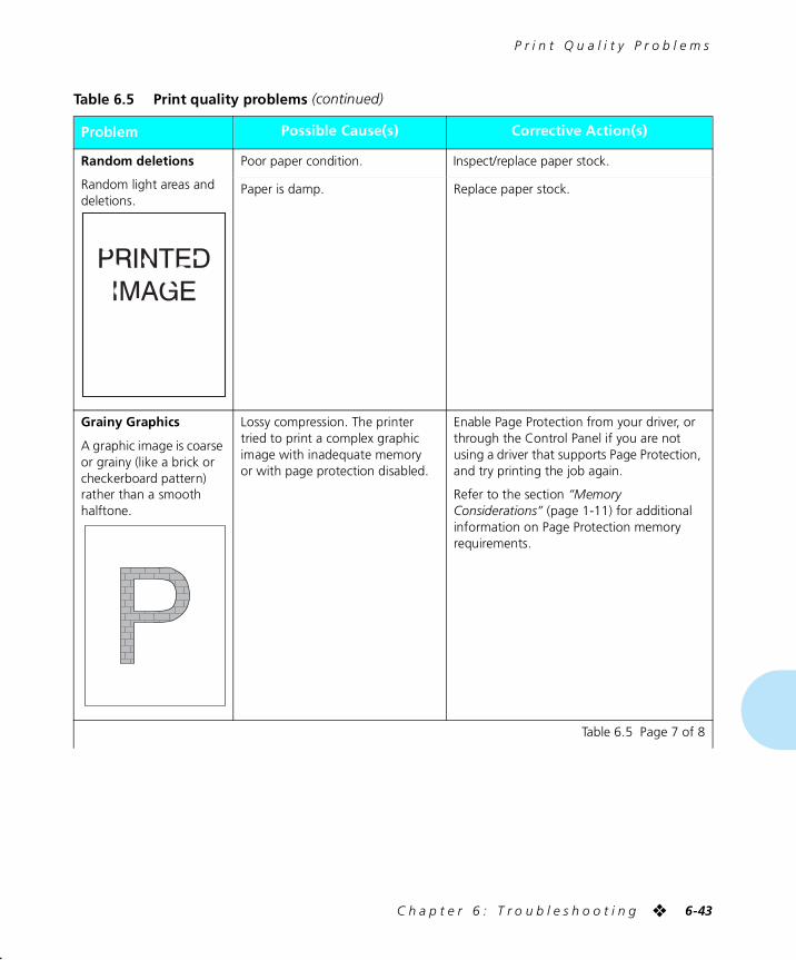
P r i n t Q u a l i t y P r o b l e m s
C h a p t e r 6 : T r o u b l e s h o o t i n g ❖ 6-43
Random deletions
Random light areas and deletions.
Poor paper condition. Inspect/replace paper stock.
Paper is damp. Replace paper stock.
Grainy Graphics
A graphic image is coarse or grainy (like a brick or checkerboard pattern) rather than a smooth halftone.
Lossy compression. The printer tried to print a complex graphic image with inadequate memory or with page protection disabled.
Enable Page Protection from your driver, or through the Control Panel if you are not using a driver that supports Page Protection, and try printing the job again.
Refer to the section “Memory Considerations” (page 1-11) for additional information on Page Protection memory requirements.
Table 6.5 Print quality problems (continued)
Problem Possible Cause(s) Corrective Action(s)
Table 6.5 Page 7 of 8
chapter6.frm Page 43 Friday, July 11, 1997 8:20 PM

P r i n t Q u a l i t y P r o b l e m s
6-44 ❖ D o c u P r i n t 4 5 1 7 / 4 5 1 7 m p U s e r G u i d e
Broken Page/Page Too Complex
The printed image is missing all of the image print after a straight line.
The printer tried to print a complex graphic image with inadequate memory or with Page Protection disabled.
Enable Page Protection from your driver, or through the Control Panel if you are not using a driver that supports Page Protection, and try printing the job again.
Refer to the section “Memory Considerations” (page 1-11) for additional information on Page Protection memory requirements.
Table 6.5 Print quality problems (continued)
Problem Possible Cause(s) Corrective Action(s)
Table 6.5 Page 8 of 8
chapter6.frm Page 44 Friday, July 11, 1997 8:20 PM
Appendix A
A p p e n d i x A : O r d e r i n g P r i n t e r O p t i o n s ❖ A-1
Ordering Printer Options AppendixA
chaptera.frm Page 1 Friday, July 11, 1997 8:22 PM
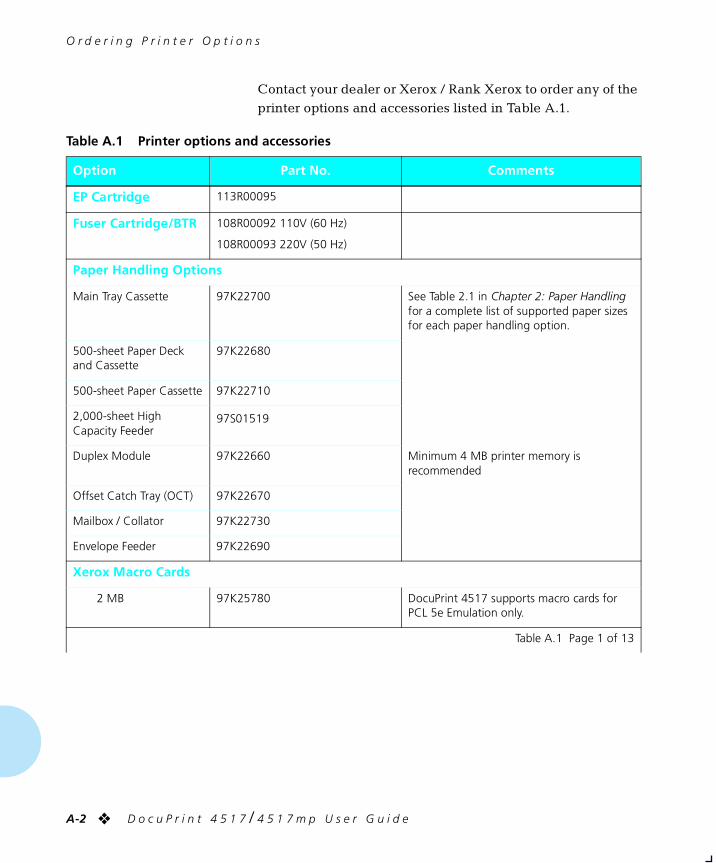
O r d e r i n g P r i n t e r O p t i o n s
A-2 ❖ D o c u P r i n t 4 5 1 7 / 4 5 1 7 m p U s e r G u i d e
Contact your dealer or Xerox / Rank Xerox to order any of the
printer options and accessories listed in Table A.1.
Table A.1 Printer options and accessories
Option Part No. Comments
EP Cartridge 113R00095
Fuser Cartridge/BTR 108R00092 110V (60 Hz)
108R00093 220V (50 Hz)
Paper Handling Options
Main Tray Cassette 97K22700 See Table 2.1 in Chapter 2: Paper Handling for a complete list of supported paper sizes for each paper handling option.
500-sheet Paper Deck and Cassette
97K22680
500-sheet Paper Cassette 97K22710
2,000-sheet High Capacity Feeder
97S01519
Duplex Module 97K22660 Minimum 4 MB printer memory is recommended
Offset Catch Tray (OCT) 97K22670
Mailbox / Collator 97K22730
Envelope Feeder 97K22690
Xerox Macro Cards
2 MB 97K25780 DocuPrint 4517 supports macro cards for PCL 5e Emulation only.
Table A.1 Page 1 of 13
chaptera.frm Page 2 Friday, July 11, 1997 8:22 PM
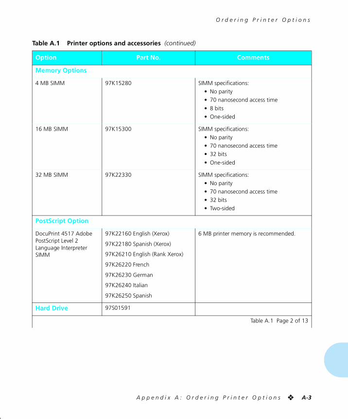
O r d e r i n g P r i n t e r O p t i o n s
A p p e n d i x A : O r d e r i n g P r i n t e r O p t i o n s ❖ A-3
Memory Options
4 MB SIMM 97K15280 SIMM specifications:
• No parity
• 70 nanosecond access time
• 8 bits
• One-sided
16 MB SIMM 97K15300 SIMM specifications:
• No parity
• 70 nanosecond access time
• 32 bits
• One-sided
32 MB SIMM 97K22330 SIMM specifications:
• No parity
• 70 nanosecond access time
• 32 bits
• Two-sided
PostScript Option
DocuPrint 4517 Adobe PostScript Level 2 Language Interpreter SIMM
97K22160 English (Xerox)
97K22180 Spanish (Xerox)
97K26210 English (Rank Xerox)
97K26220 French
97K26230 German
97K26240 Italian
97K26250 Spanish
6 MB printer memory is recommended.
Hard Drive 97S01591
Table A.1 Printer options and accessories (continued)
Option Part No. Comments
Table A.1 Page 2 of 13
chaptera.frm Page 3 Friday, July 11, 1997 8:22 PM
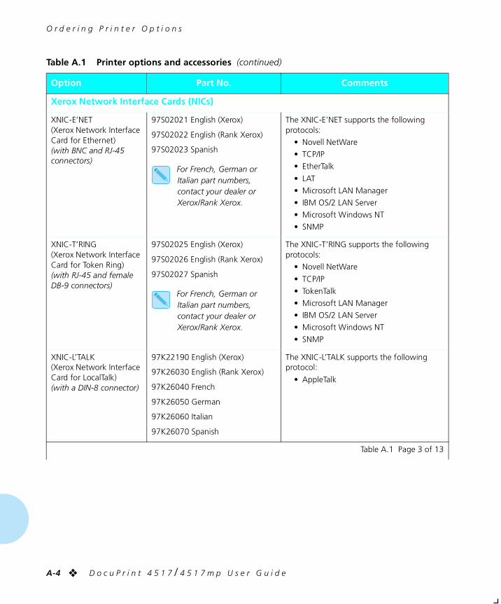
O r d e r i n g P r i n t e r O p t i o n s
A-4 ❖ D o c u P r i n t 4 5 1 7 / 4 5 1 7 m p U s e r G u i d e
Xerox Network Interface Cards (NICs)
XNIC-E’NET(Xerox Network Interface Card for Ethernet)(with BNC and RJ-45 connectors)
97S02021 English (Xerox)
97S02022 English (Rank Xerox)
97S02023 Spanish
For French, German or Italian part numbers, contact your dealer or Xerox/Rank Xerox.
The XNIC-E’NET supports the following protocols:
• Novell NetWare
• TCP/IP
• EtherTalk
• LAT
• Microsoft LAN Manager
• IBM OS/2 LAN Server
• Microsoft Windows NT
• SNMP
XNIC-T’RING(Xerox Network Interface Card for Token Ring)(with RJ-45 and female DB-9 connectors)
97S02025 English (Xerox)
97S02026 English (Rank Xerox)
97S02027 Spanish
For French, German or Italian part numbers, contact your dealer or Xerox/Rank Xerox.
The XNIC-T’RING supports the following protocols:
• Novell NetWare
• TCP/IP
• TokenTalk
• Microsoft LAN Manager
• IBM OS/2 LAN Server
• Microsoft Windows NT
• SNMP
XNIC-L’TALK(Xerox Network Interface Card for LocalTalk)(with a DIN-8 connector)
97K22190 English (Xerox)
97K26030 English (Rank Xerox)
97K26040 French
97K26050 German
97K26060 Italian
97K26070 Spanish
The XNIC-L’TALK supports the following protocol:
• AppleTalk
Table A.1 Printer options and accessories (continued)
Option Part No. Comments
Table A.1 Page 3 of 13
chaptera.frm Page 4 Friday, July 11, 1997 8:22 PM
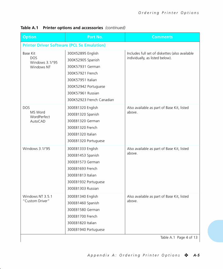
O r d e r i n g P r i n t e r O p t i o n s
A p p e n d i x A : O r d e r i n g P r i n t e r O p t i o n s ❖ A-5
Printer Driver Software (PCL 5e Emulation)
Base KitDOSWindows 3.1/’95Windows NT
300X52895 English
300K52905 Spanish
300K57931 German
300K57921 French
300K57951 Italian
300K52942 Portuguese
300K57961 Russian
300K52923 French Canadian
Includes full set of diskettes (also available individually, as listed below).
DOSMS WordWordPerfectAutoCAD
300E81320 English
300E81320 Spanish
300E81320 German
300E81320 French
300E81320 Italian
300E81320 Portuguese
Also available as part of Base Kit, listed above.
Windows 3.1/’95 300E81333 English
300E81453 Spanish
300E81573 German
300E81693 French
300E81813 Italian
300E81932 Portuguese
300E81303 Russian
Also available as part of Base Kit, listed above.
Windows NT 3.5.1“Custom Driver”
300E81340 English
300E81460 Spanish
300E81580 German
300E81700 French
300E81820 Italian
300E81940 Portuguese
Also available as part of Base Kit, listed above.
Table A.1 Printer options and accessories (continued)
Option Part No. Comments
Table A.1 Page 4 of 13
chaptera.frm Page 5 Friday, July 11, 1997 8:22 PM
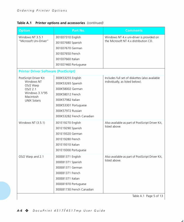
O r d e r i n g P r i n t e r O p t i o n s
A-6 ❖ D o c u P r i n t 4 5 1 7 / 4 5 1 7 m p U s e r G u i d e
Windows NT 3.5.1“Microsoft Uni-Driver”
301E07310 English
301E07680 Spanish
301E07670 German
301E07650 French
301E07660 Italian
301E07460 Portuguese
Windows NT 4.x uni-driver is provided on the Microsoft NT 4.x distribution CD.
Printer Driver Software (PostScript)
PostScript Driver KitWindows NTOS/2 WarpOS/2 2.1Windows 3.1/’95MacintoshUNIX Solaris
300K53255 English
300K53265 Spanish
300K58002 German
300K58012 French
300K57982 Italian
300K53301 Portuguese
300K57972 Russian
300K53282 French Canadian
Includes full set of diskettes (also available individually, as listed below).
Windows NT (3.5.1) 301E19270 English
301E19290 Spanish
301E19320 German
301E19280 French
301E19310 Italian
301E19300 Portuguese
Also available as part of PostScript Driver Kit, listed above.
OS/2 Warp and 2.1 300E81371 English
300E81371 Spanish
300E81371 German
300E81371 French
300E81371 Italian
300E81970 Portuguese
300E81730 French Canadian
Also available as part of PostScript Driver Kit, listed above.
Table A.1 Printer options and accessories (continued)
Option Part No. Comments
Table A.1 Page 5 of 13
chaptera.frm Page 6 Friday, July 11, 1997 8:22 PM
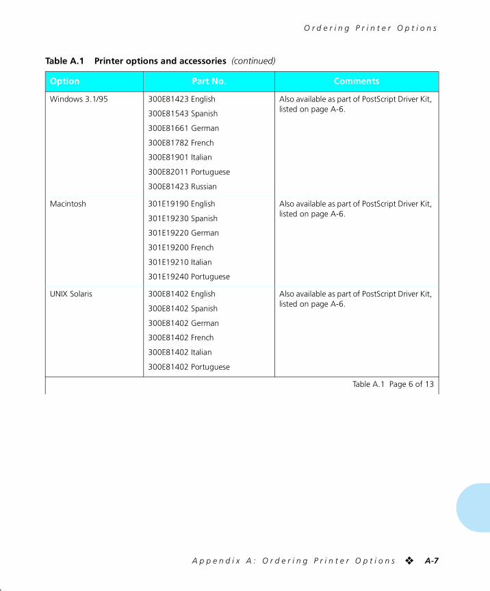
O r d e r i n g P r i n t e r O p t i o n s
A p p e n d i x A : O r d e r i n g P r i n t e r O p t i o n s ❖ A-7
Windows 3.1/95 300E81423 English
300E81543 Spanish
300E81661 German
300E81782 French
300E81901 Italian
300E82011 Portuguese
300E81423 Russian
Also available as part of PostScript Driver Kit, listed on page A-6.
Macintosh 301E19190 English
301E19230 Spanish
301E19220 German
301E19200 French
301E19210 Italian
301E19240 Portuguese
Also available as part of PostScript Driver Kit, listed on page A-6.
UNIX Solaris 300E81402 English
300E81402 Spanish
300E81402 German
300E81402 French
300E81402 Italian
300E81402 Portuguese
Also available as part of PostScript Driver Kit, listed on page A-6.
Table A.1 Printer options and accessories (continued)
Option Part No. Comments
Table A.1 Page 6 of 13
chaptera.frm Page 7 Friday, July 11, 1997 8:22 PM
O r d e r i n g P r i n t e r O p t i o n s
A-8 ❖ D o c u P r i n t 4 5 1 7 / 4 5 1 7 m p U s e r G u i d e
Additional Printer Drivers
OS/2 Warp and 2.1(PCL 5e Emulation)
300E81381 English
300E81501 Spanish
300E81980 Portuguese
For French, German or Italian part numbers, contact your dealer or Xerox/Rank Xerox.
UNIX Sun OS 300E81411 English
300E81411 Spanish
300E81411 German
300E81411 French
300E81411 Italian
300E81411 Portuguese
UNIX SCO 300E83301 English
300E83301 Spanish
300E83301 German
300E83301 French
300E83301 Italian
300E83301 Portuguese
UNIX RS6000 300E83361 English
300E83361 Spanish
300E83361 German
300E83361 French
300E83361 Italian
300E83361 Portuguese
Table A.1 Printer options and accessories (continued)
Option Part No. Comments
Table A.1 Page 7 of 13
chaptera.frm Page 8 Friday, July 11, 1997 8:22 PM
O r d e r i n g P r i n t e r O p t i o n s
A p p e n d i x A : O r d e r i n g P r i n t e r O p t i o n s ❖ A-9
UNIX HP 300E83421 English
300E83421 Spanish
300E83421 German
300E83421 French
300E83421 Italian
300E83421 Portuguese
4 mm DAT format.
Network Interface Software
Ethernet and Token Ring Software and Documentation Kit
300K68080 English
300K68100 Spanish
300K68130 German
300K68090 French/French Canadian
300K68120 Italian
300K68110 Portuguese
Includes XNIC-E’NET/T’RING Configuration Guide and full set of diskettes (also available individually, as listed below). Does not include Xerox Network Interface Card (XNIC).
Utilities For:LAN Manager,LAN Server,Novell NetWare (TES)
301E20530 Also available as part of Ethernet and Token Ring Software and Documentation Kit, listed above.
Xerox Network Port Monitor for Windows NT
301E10060 Also available as part of Ethernet and Token Ring Software and Documentation Kit, listed above.
UNIX Installation Utility 301E20540 Also available as part of Ethernet and Token Ring Software and Documentation Kit, listed above.
SNMP MIB (DOS format) 300E82062 Available in Xerox Software Library, Xerox web page and Xerox FTP site.
SNMP MIB (tar format) 300E82072 Available in Xerox Software Library, Xerox web page and Xerox FTP site.
Sun Platforms Installer for Ethernet and Token Ring
300K60900 CD-ROM format.
Table A.1 Printer options and accessories (continued)
Option Part No. Comments
Table A.1 Page 8 of 13
chaptera.frm Page 9 Friday, July 11, 1997 8:22 PM
O r d e r i n g P r i n t e r O p t i o n s
A-10 ❖ D o c u P r i n t 4 5 1 7 / 4 5 1 7 m p U s e r G u i d e
User Documentation
DocuPrint 4517/4517mp Base Documentation Kit
720S53751 English (Xerox)
721S53751 English (Rank Xerox)
720S54751 German
720S55751 French
720S56751 Spanish (Xerox)
721S56751 Spanish (Rank Xerox)
720S57751 Italian
720S58751 Portuguese
720S59751 French Canadian
721S53141 Russian
Includes Setting Up Guide, User Guide and Quick Reference Card (also available individually, as listed below).
DocuPrint 4517/4517mp Setting Up Guide
720P53761 English (Xerox)
721P53761 English (Rank Xerox)
720P54761 German
720P55761 French
720P56761 Spanish (Xerox)
721P56761 Spanish (Rank Xerox)
720P57761 Italian
720P58761 Portuguese
720P59761 French Canadian
721P53221 Russian
Also available as part of Base Documentation Kit, listed above.
Table A.1 Printer options and accessories (continued)
Option Part No. Comments
Table A.1 Page 9 of 13
chaptera.frm Page 10 Friday, July 11, 1997 8:22 PM
O r d e r i n g P r i n t e r O p t i o n s
A p p e n d i x A : O r d e r i n g P r i n t e r O p t i o n s ❖ A-11
DocuPrint 4517/4517mp User Guide
720P53771 English (Xerox)
721P53771 English (Rank Xerox)
720P54771 German
720P55771 French
720P56771 Spanish (Xerox)
721P56771 Spanish (Rank Xerox)
720P57771 Italian
720P58771 Portuguese
720P59771 French Canadian
721P53231 Russian
Also available as part of Base Documentation Kit, listed above.
DocuPrint 4517/4517mp Quick Reference Card
720P53781 English (Xerox)
721P53781 English (Rank Xerox)
720P54781 German
720P55781 French
720P56781 Spanish (Xerox)
721P56781 Spanish (Rank Xerox)
720P57781 Italian
720P58781 Portuguese
720P59781 French Canadian
721P53241 Russian
Also available as part of Base Documentation Kit, listed on page A-10.
Table A.1 Printer options and accessories (continued)
Option Part No. Comments
Table A.1 Page 10 of 13
chaptera.frm Page 11 Friday, July 11, 1997 8:22 PM
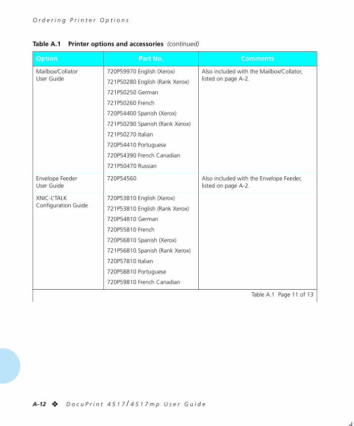
O r d e r i n g P r i n t e r O p t i o n s
A-12 ❖ D o c u P r i n t 4 5 1 7 / 4 5 1 7 m p U s e r G u i d e
Mailbox/CollatorUser Guide
720P59970 English (Xerox)
721P50280 English (Rank Xerox)
721P50250 German
721P50260 French
720P54400 Spanish (Xerox)
721P50290 Spanish (Rank Xerox)
721P50270 Italian
720P54410 Portuguese
720P54390 French Canadian
721P50470 Russian
Also included with the Mailbox/Collator, listed on page A-2.
Envelope FeederUser Guide
720P54560 Also included with the Envelope Feeder, listed on page A-2.
XNIC-L’TALK Configuration Guide
720P53810 English (Xerox)
721P53810 English (Rank Xerox)
720P54810 German
720P55810 French
720P56810 Spanish (Xerox)
721P56810 Spanish (Rank Xerox)
720P57810 Italian
720P58810 Portuguese
720P59810 French Canadian
Table A.1 Printer options and accessories (continued)
Option Part No. Comments
Table A.1 Page 11 of 13
chaptera.frm Page 12 Friday, July 11, 1997 8:22 PM
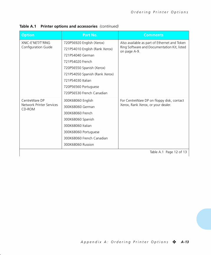
O r d e r i n g P r i n t e r O p t i o n s
A p p e n d i x A : O r d e r i n g P r i n t e r O p t i o n s ❖ A-13
XNIC-E’NET/T’RING Configuration Guide
720P56920 English (Xerox)
721P54010 English (Rank Xerox)
721P54040 German
721P54020 French
720P56550 Spanish (Xerox)
721P54050 Spanish (Rank Xerox)
721P54030 Italian
720P56560 Portuguese
720P56530 French Canadian
Also available as part of Ethernet and Token Ring Software and Documentation Kit, listed on page A-9.
CentreWare DPNetwork Printer Services CD-ROM
300K68060 English
300K68060 German
300K68060 French
300K68060 Spanish
300K68060 Italian
300K68060 Portuguese
300K68060 French Canadian
300K68060 Russion
For CentreWare DP on floppy disk, contact Xerox, Rank Xerox, or your dealer.
Table A.1 Printer options and accessories (continued)
Option Part No. Comments
Table A.1 Page 12 of 13
chaptera.frm Page 13 Friday, July 11, 1997 8:22 PM
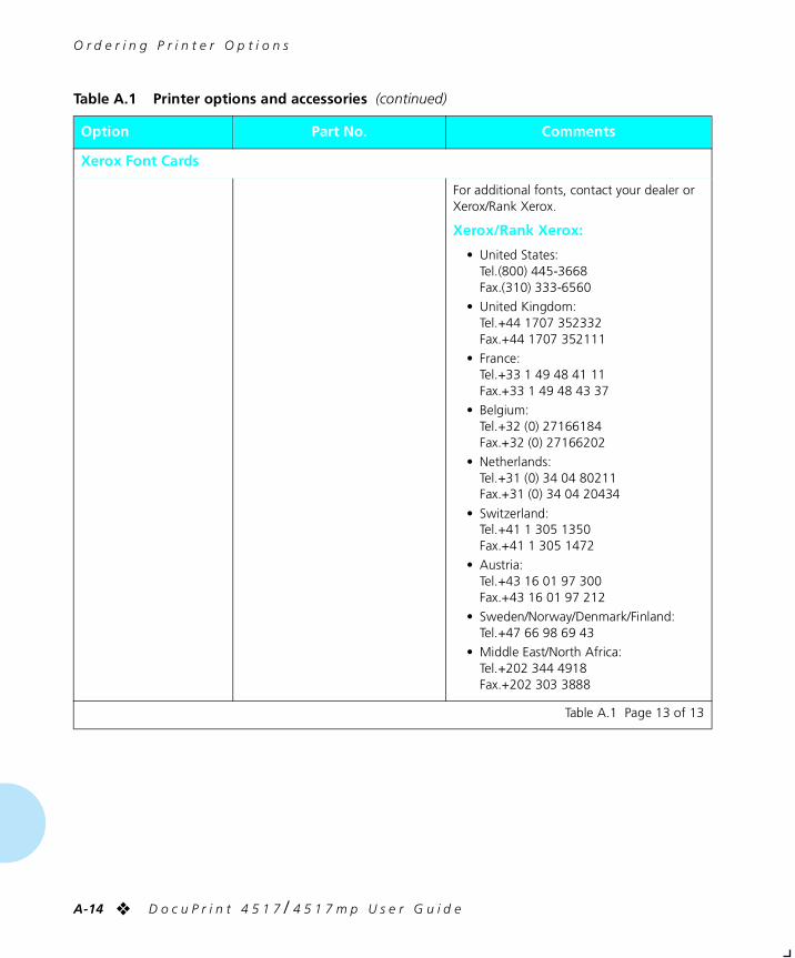
O r d e r i n g P r i n t e r O p t i o n s
A-14 ❖ D o c u P r i n t 4 5 1 7 / 4 5 1 7 m p U s e r G u i d e
Xerox Font Cards
For additional fonts, contact your dealer or Xerox/Rank Xerox.
Xerox/Rank Xerox:
• United States:Tel.(800) 445-3668Fax.(310) 333-6560
• United Kingdom:Tel.+44 1707 352332Fax.+44 1707 352111
• France:Tel.+33 1 49 48 41 11Fax.+33 1 49 48 43 37
• Belgium:Tel.+32 (0) 27166184Fax.+32 (0) 27166202
• Netherlands:Tel.+31 (0) 34 04 80211Fax.+31 (0) 34 04 20434
• Switzerland:Tel.+41 1 305 1350Fax.+41 1 305 1472
• Austria:Tel.+43 16 01 97 300Fax.+43 16 01 97 212
• Sweden/Norway/Denmark/Finland:Tel.+47 66 98 69 43
• Middle East/North Africa:Tel.+202 344 4918Fax.+202 303 3888
Table A.1 Printer options and accessories (continued)
Option Part No. Comments
Table A.1 Page 13 of 13
chaptera.frm Page 14 Friday, July 11, 1997 8:22 PM

Appendix B
A p p e n d i x B : R e p l a c i n g C o n s u m a b l e s ❖ B-1
Replacing Consumables AppendixB
Replacing the EP Cartridge .................................................. B-2
Replacing the Fuser Cartridge/BTR ...................................... B-5
chapterb.frm Page 1 Friday, July 11, 1997 8:23 PM
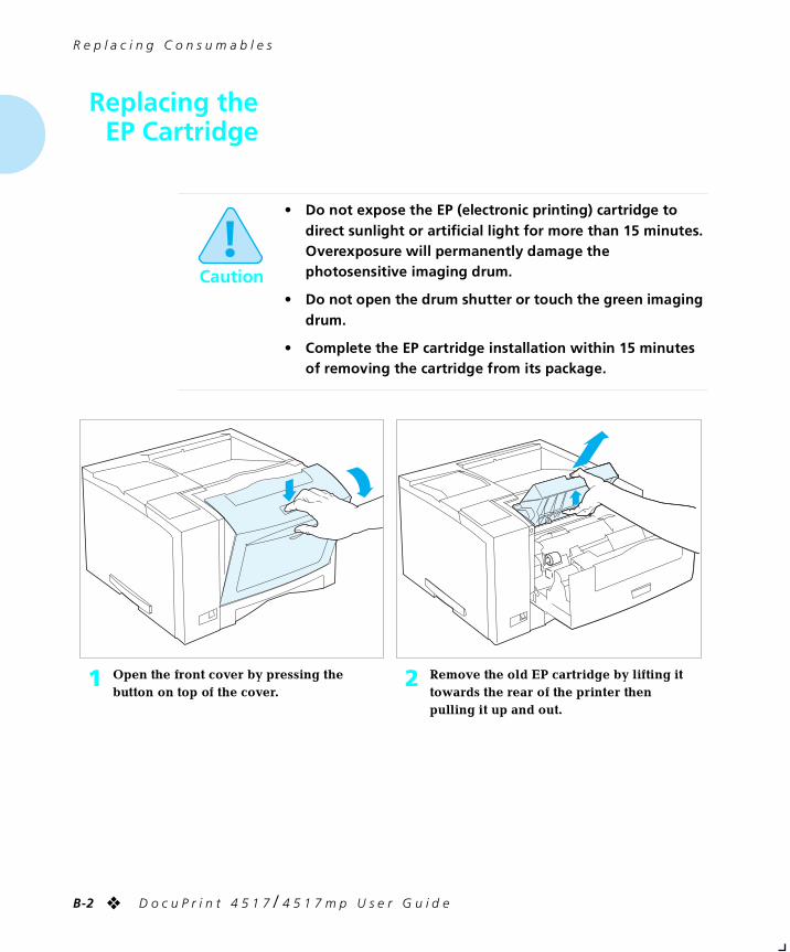
R e p l a c i n g C o n s u m a b l e s
B-2 ❖ D o c u P r i n t 4 5 1 7 / 4 5 1 7 m p U s e r G u i d e
Replacing theEP Cartridge
Caution
• Do not expose the EP (electronic printing) cartridge to direct sunlight or artificial light for more than 15 minutes. Overexposure will permanently damage the photosensitive imaging drum.
• Do not open the drum shutter or touch the green imaging drum.
• Complete the EP cartridge installation within 15 minutes of removing the cartridge from its package.
1 Open the front cover by pressing the button on top of the cover.
2 Remove the old EP cartridge by lifting it towards the rear of the printer then pulling it up and out.
chapterb.frm Page 2 Friday, July 11, 1997 8:23 PM
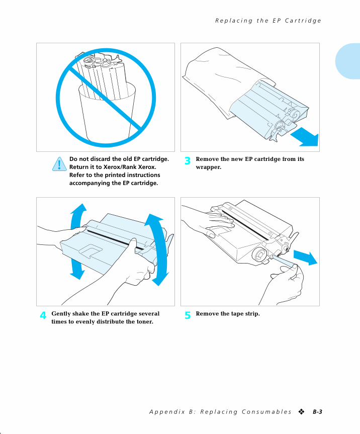
R e p l a c i n g t h e E P C a r t r i d g e
A p p e n d i x B : R e p l a c i n g C o n s u m a b l e s ❖ B-3
Do not discard the old EP cartridge. Return it to Xerox/Rank Xerox. Refer to the printed instructions accompanying the EP cartridge.
3 Remove the new EP cartridge from its wrapper.
4 Gently shake the EP cartridge several times to evenly distribute the toner.
5 Remove the tape strip.
chapterb.frm Page 3 Friday, July 11, 1997 8:23 PM
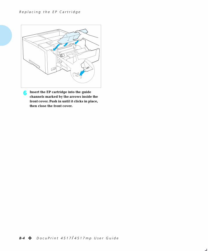
R e p l a c i n g t h e E P C a r t r i d g e
B-4 ❖ D o c u P r i n t 4 5 1 7 / 4 5 1 7 m p U s e r G u i d e
6 Insert the EP cartridge into the guide channels marked by the arrows inside the front cover. Push in until it clicks in place, then close the front cover.
chapterb.frm Page 4 Friday, July 11, 1997 8:23 PM
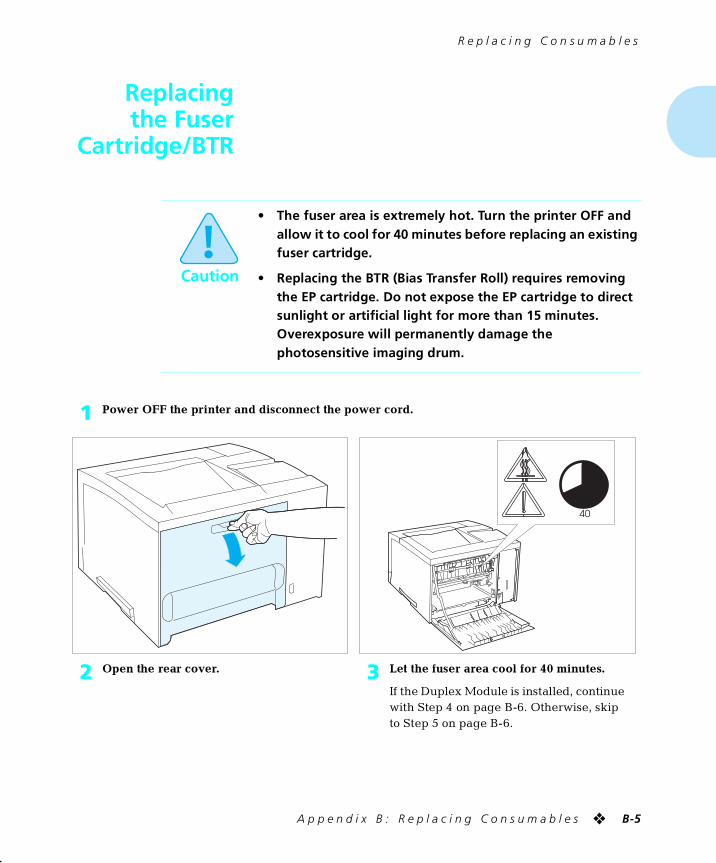
R e p l a c i n g C o n s u m a b l e s
A p p e n d i x B : R e p l a c i n g C o n s u m a b l e s ❖ B-5
Replacingthe Fuser
Cartridge/BTR
Caution
• The fuser area is extremely hot. Turn the printer OFF and allow it to cool for 40 minutes before replacing an existing fuser cartridge.
• Replacing the BTR (Bias Transfer Roll) requires removing the EP cartridge. Do not expose the EP cartridge to direct sunlight or artificial light for more than 15 minutes. Overexposure will permanently damage the photosensitive imaging drum.
1 Power OFF the printer and disconnect the power cord.
2 Open the rear cover. 3 Let the fuser area cool for 40 minutes.
If the Duplex Module is installed, continue with Step 4 on page B-6. Otherwise, skip to Step 5 on page B-6.
40
chapterb.frm Page 5 Friday, July 11, 1997 8:23 PM
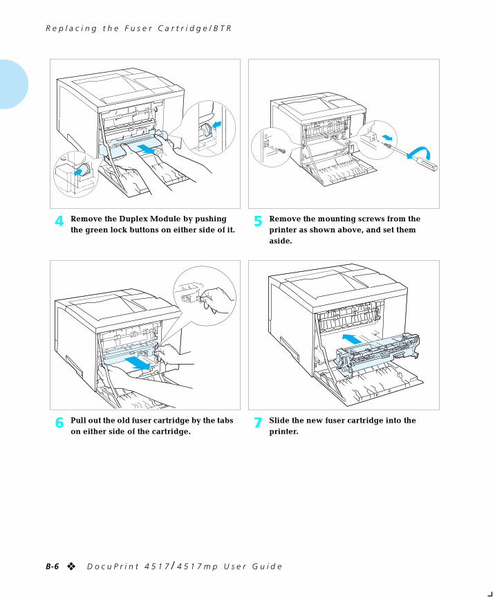
R e p l a c i n g t h e F u s e r C a r t r i d g e / B T R
B-6 ❖ D o c u P r i n t 4 5 1 7 / 4 5 1 7 m p U s e r G u i d e
4 Remove the Duplex Module by pushing the green lock buttons on either side of it.
5 Remove the mounting screws from the printer as shown above, and set them aside.
6 Pull out the old fuser cartridge by the tabs on either side of the cartridge.
7 Slide the new fuser cartridge into the printer.
chapterb.frm Page 6 Friday, July 11, 1997 8:23 PM
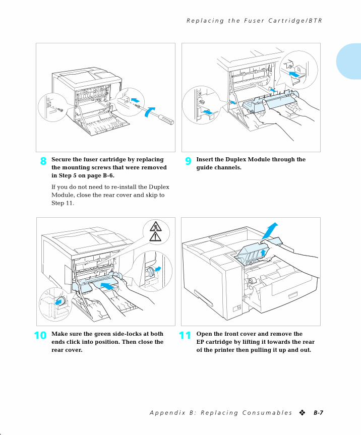
R e p l a c i n g t h e F u s e r C a r t r i d g e / B T R
A p p e n d i x B : R e p l a c i n g C o n s u m a b l e s ❖ B-7
8 Secure the fuser cartridge by replacing the mounting screws that were removed in Step 5 on page B-6.
If you do not need to re-install the Duplex Module, close the rear cover and skip to Step 11.
9 Insert the Duplex Module through the guide channels.
10 Make sure the green side-locks at both ends click into position. Then close the rear cover.
11 Open the front cover and remove the EP cartridge by lifting it towards the rear of the printer then pulling it up and out.
chapterb.frm Page 7 Friday, July 11, 1997 8:23 PM
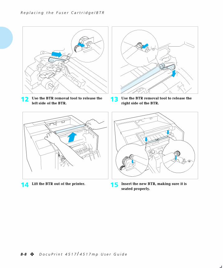
R e p l a c i n g t h e F u s e r C a r t r i d g e / B T R
B-8 ❖ D o c u P r i n t 4 5 1 7 / 4 5 1 7 m p U s e r G u i d e
12 Use the BTR removal tool to release the left side of the BTR.
13 Use the BTR removal tool to release the right side of the BTR.
14 Lift the BTR out of the printer. 15 Insert the new BTR, making sure it is seated properly.
chapterb.frm Page 8 Friday, July 11, 1997 8:23 PM
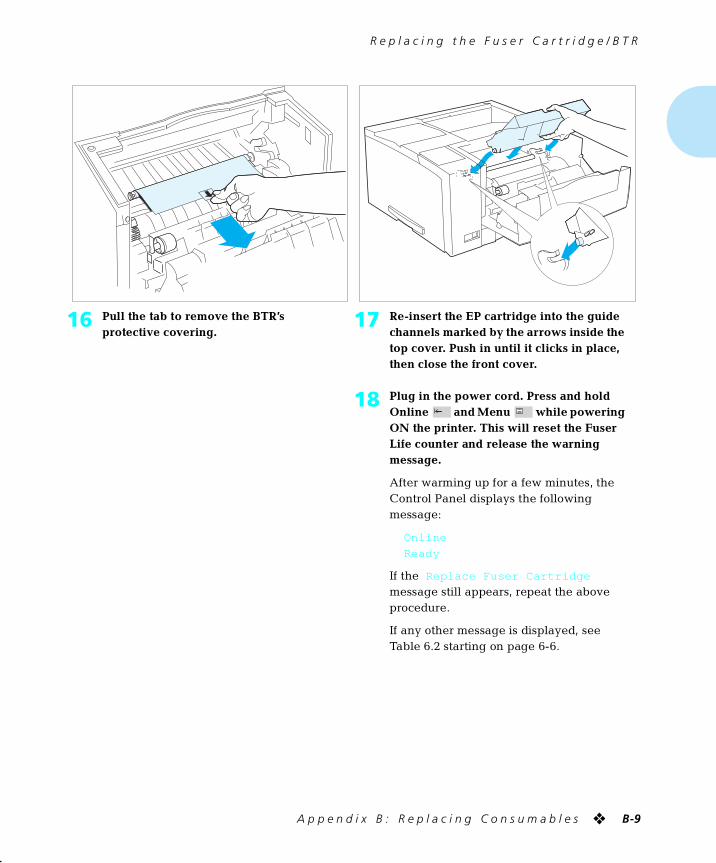
R e p l a c i n g t h e F u s e r C a r t r i d g e / B T R
A p p e n d i x B : R e p l a c i n g C o n s u m a b l e s ❖ B-9
16 Pull the tab to remove the BTR’s protective covering.
17 Re-insert the EP cartridge into the guide channels marked by the arrows inside the top cover. Push in until it clicks in place, then close the front cover.
18 Plug in the power cord. Press and hold Online and Menu while powering ON the printer. This will reset the Fuser Life counter and release the warning message.
After warming up for a few minutes, the Control Panel displays the following message:
Online
Ready
If the Replace Fuser Cartridge
message still appears, repeat the above procedure.
If any other message is displayed, see Table 6.2 starting on page 6-6.
chapterb.frm Page 9 Friday, July 11, 1997 8:23 PM

B-10 ❖ D o c u P r i n t 4 5 1 7 / 4 5 1 7 m p U s e r G u i d e
chapterb.frm Page 10 Friday, July 11, 1997 8:23 PM
Appendix C
A p p e n d i x C : I n s t a l l i n g a n d R e m o v i n g P r i n t e r O p t i o n s ❖ C-1
Installing and Removing Printer Options AppendixC
Precautions ............................................................................ C-3
Memory SIMMs ..................................................................... C-4
Installing a Memory SIMM .................................................... C-4
Removing a Memory SIMM .................................................. C-7
PostScript SIMM .................................................................... C-9
Installing a PostScript SIMM .................................................. C-9
Removing a PostScript SIMM .............................................. C-12
Hard Drive ........................................................................... C-15
Installing the Hard Drive ..................................................... C-15
Removing the Hard Drive .................................................... C-18
Duplex Module ................................................................... C-20
Installing the Duplex Module .............................................. C-20
Removing the Duplex Module ............................................ C-22
chapterc.frm Page 1 Friday, July 11, 1997 9:17 PM
I n s t a l l i n g a n d R e m o v i n g P r i n t e r O p t i o n s
C-2 ❖ D o c u P r i n t 4 5 1 7 / 4 5 1 7 m p U s e r G u i d e
500-sheet Paper Deck and Cassette .................................. C-23
Installing One 500-sheet Paper Deck and Cassette .............. C-23
Installing Two 500-sheet Paper Decks and Cassettes ........... C-26
Removing a 500-sheet Paper Deck and Cassette ................. C-30
2,000-sheet High Capacity Feeder (HCF) ........................... C-32
Installing the 2,000-sheet High Capacity Feeder .................. C-33
Removing the 2,000-sheet High Capacity Feeder ................ C-37
Offset Catch Tray (OCT) ..................................................... C-39
Installing the OCT ............................................................... C-39
Removing the OCT ............................................................. C-42
Mailbox/Collator ................................................................. C-44
Installing the Mailbox/Collator ............................................ C-44
Removing the Mailbox/Collator ........................................... C-47
Envelope Feeder ................................................................. C-49
Installing the Envelope Feeder ............................................ C-49
Removing the Envelope Feeder ........................................... C-52
Font Cards and Macro Cards .............................................. C-54
Xerox Network Interface Card (XNIC) ............................... C-55
Installing the XNIC .............................................................. C-56
Removing the XNIC ............................................................ C-60
chapterc.frm Page 2 Friday, July 11, 1997 9:17 PM
I n s t a l l i n g a n d R e m o v i n g P r i n t e r O p t i o n s
A p p e n d i x C : I n s t a l l i n g a n d R e m o v i n g P r i n t e r O p t i o n s ❖ C-3
Precautions The DocuPrint 4517 printer options are easy to install.
Installing and testing any one option is likely to take 5 to 15 minutes.
Before installing or removing any printer option, take the
precautionary steps outlined below.
Caution
POWER OFF THE PRINTER: The printer determines which options are installed through a self-test. The self-test is run when you power ON the printer. Therefore, for proper operation, you must power OFF the printer before installing/removing an option, then power it back ON after installing/removing an option.
Caution
DISCONNECT THE POWER CORD: Never remove the printer controller board while the printer is plugged in.
To avoid the possibility of electrical shock, always disconnect the power cord when installing or removing ANY internal or external printer option.
Caution
DISCHARGE STATIC ELECTRICITY: The controller board and internal printer options (SIMMs, network interface cards, and the hard drive) are sensitive to static electricity. Before installing or removing an internal option, discharge static electricity from your body by touching something metal, such as the metal back plate on any device plugged into a grounded power source. If you walk around before finishing the installation, again discharge any static electricity.
chapterc.frm Page 3 Friday, July 11, 1997 9:17 PM
I n s t a l l i n g a n d R e m o v i n g P r i n t e r O p t i o n s
C-4 ❖ D o c u P r i n t 4 5 1 7 / 4 5 1 7 m p U s e r G u i d e
MemorySIMMs
This section contains two sets of instructions:
• “Installing a Memory SIMM” (page C-4)
• “Removing a Memory SIMM” (page C-7)
Installing aMemory SIMM
Note
Memory SIMMs for the DocuPrint 4517 are available in the
following sizes:
• one-sided 4 MB and 16 MB
• two-sided 32 MB
(See Appendix A: Ordering Printer Options for ordering additional memory.)
Caution
SIMMs and controller boards are sensitive to static electricity. Before installing a SIMM, discharge static electricity from your body by touching something metal, such as the metal back plate on any device plugged into a grounded power source. If you walk around before finishing the installation, again discharge any static electricity.
Never remove the printer controller board while the printer is plugged in.
Note
Either 1 MB or 4 MB of the printer’s memory (depending on the version of the printer) may become unusable when
2-sided 32 MB SIMMs are installed (or other non-Xerox 2-sided SIMMs, such as 8 MB or 2 MB). Thus the total system memory may be less than the sum of resident and SIMM
memory when 2-sided SIMMS are used. To maximize usable memory, we suggest selecting slot SIMM3 for a 2-sided SIMM and not using 2 MB SIMMs in slot SIMM2.
chapterc.frm Page 4 Friday, July 11, 1997 9:17 PM
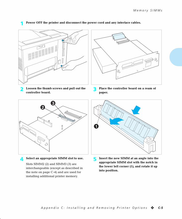
M e m o r y S I M M s
A p p e n d i x C : I n s t a l l i n g a n d R e m o v i n g P r i n t e r O p t i o n s ❖ C-5
1 Power OFF the printer and disconnect the power cord and any interface cables.
2 Loosen the thumb screws and pull out the controller board.
3 Place the controller board on a ream of paper.
4 Select an appropriate SIMM slot to use.
Slots SIMM2 (2) and SIMM3 (3) are interchangeable (except as described in the note on page C-4) and are used for installing additional printer memory.
5 Insert the new SIMM at an angle into the appropriate SIMM slot with the notch in the lower left corner (1), and rotate it up into position.
chapterc.frm Page 5 Friday, July 11, 1997 9:17 PM
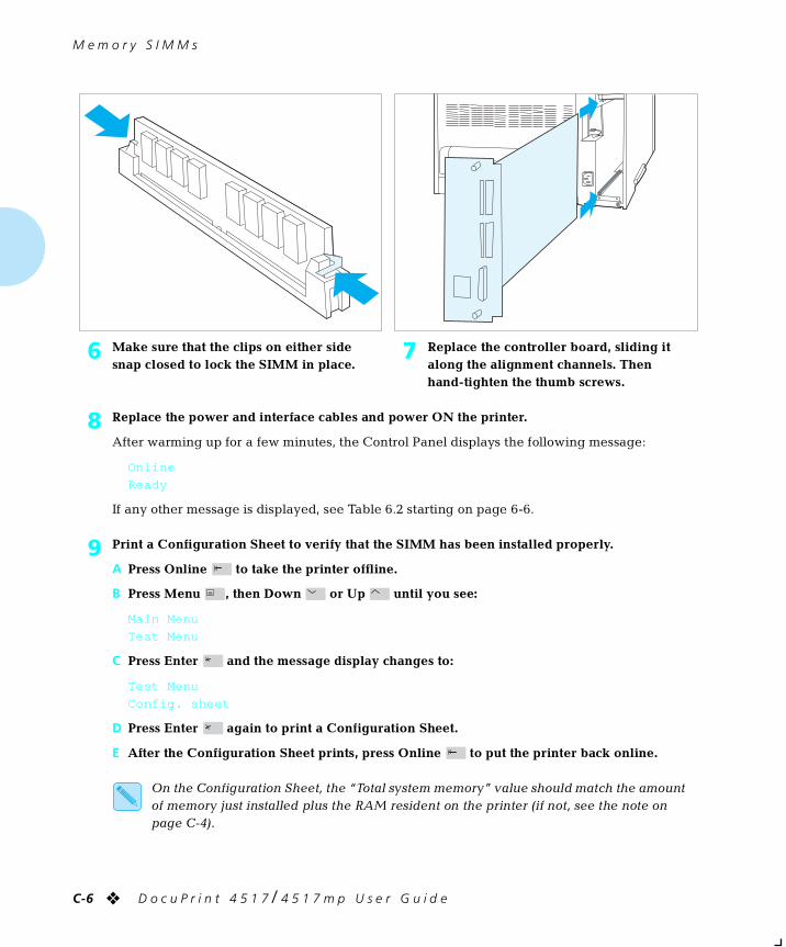
M e m o r y S I M M s
C-6 ❖ D o c u P r i n t 4 5 1 7 / 4 5 1 7 m p U s e r G u i d e
6 Make sure that the clips on either side snap closed to lock the SIMM in place.
7 Replace the controller board, sliding it along the alignment channels. Then hand-tighten the thumb screws.
8 Replace the power and interface cables and power ON the printer.
After warming up for a few minutes, the Control Panel displays the following message:
Online
Ready
If any other message is displayed, see Table 6.2 starting on page 6-6.
9 Print a Configuration Sheet to verify that the SIMM has been installed properly.
A Press Online to take the printer offline.
B Press Menu , then Down or Up until you see:
Main Menu
Test Menu
C Press Enter and the message display changes to:
Test Menu
Config. sheet
D Press Enter again to print a Configuration Sheet.
E After the Configuration Sheet prints, press Online to put the printer back online.
On the Configuration Sheet, the “Total system memory” value should match the amount of memory just installed plus the RAM resident on the printer (if not, see the note on page C-4).
chapterc.frm Page 6 Friday, July 11, 1997 9:17 PM
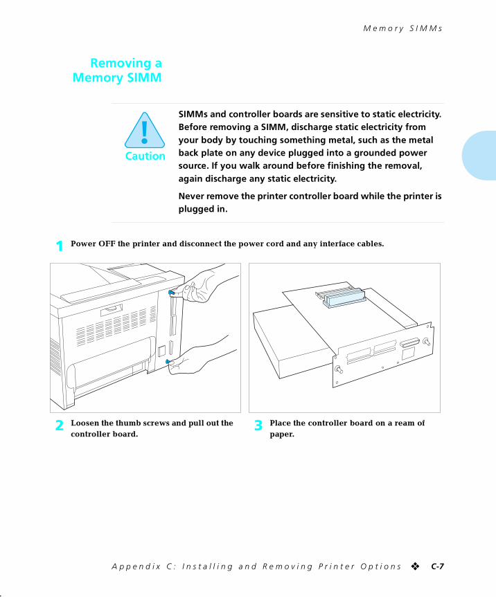
M e m o r y S I M M s
A p p e n d i x C : I n s t a l l i n g a n d R e m o v i n g P r i n t e r O p t i o n s ❖ C-7
Removing aMemory SIMM
Caution
SIMMs and controller boards are sensitive to static electricity. Before removing a SIMM, discharge static electricity from your body by touching something metal, such as the metal back plate on any device plugged into a grounded power source. If you walk around before finishing the removal, again discharge any static electricity.
Never remove the printer controller board while the printer is plugged in.
1 Power OFF the printer and disconnect the power cord and any interface cables.
2 Loosen the thumb screws and pull out the controller board.
3 Place the controller board on a ream of paper.
chapterc.frm Page 7 Friday, July 11, 1997 9:17 PM
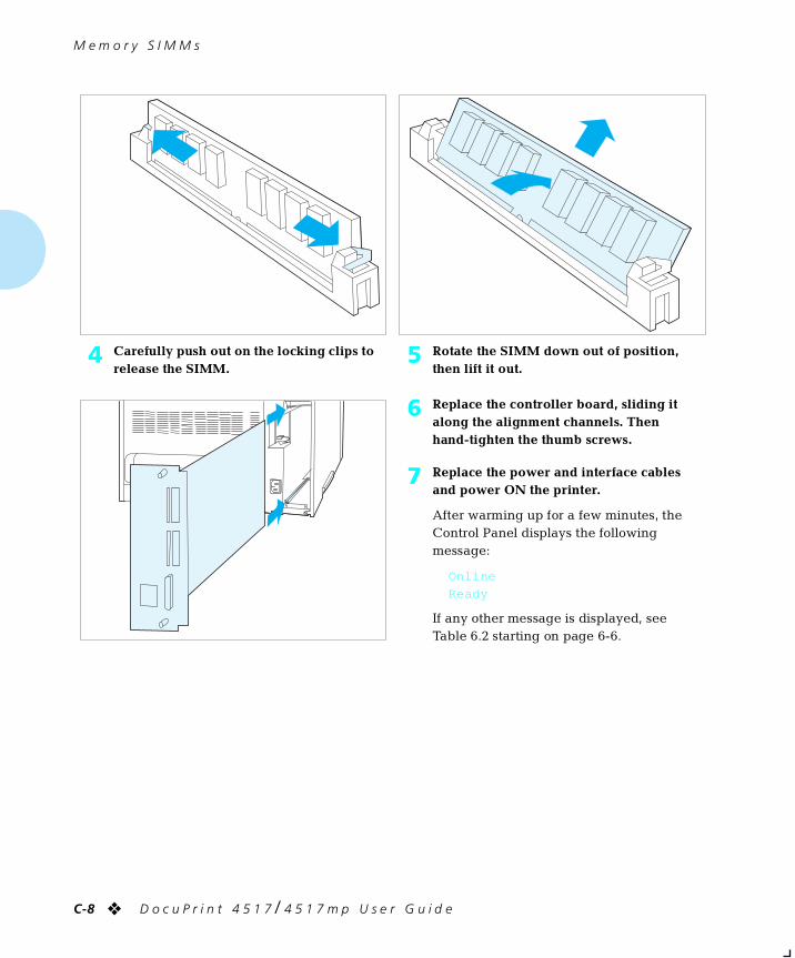
M e m o r y S I M M s
C-8 ❖ D o c u P r i n t 4 5 1 7 / 4 5 1 7 m p U s e r G u i d e
4 Carefully push out on the locking clips to release the SIMM.
5 Rotate the SIMM down out of position, then lift it out.
6 Replace the controller board, sliding it along the alignment channels. Then hand-tighten the thumb screws.
7 Replace the power and interface cables and power ON the printer.
After warming up for a few minutes, the Control Panel displays the following message:
Online
Ready
If any other message is displayed, see Table 6.2 starting on page 6-6.
chapterc.frm Page 8 Friday, July 11, 1997 9:17 PM
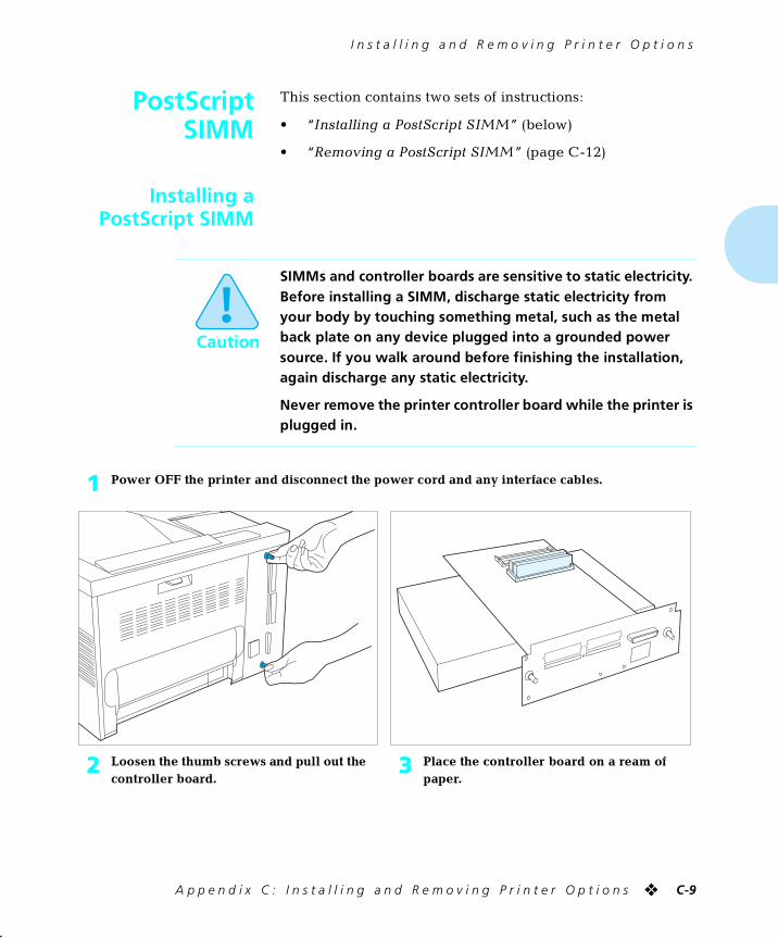
I n s t a l l i n g a n d R e m o v i n g P r i n t e r O p t i o n s
A p p e n d i x C : I n s t a l l i n g a n d R e m o v i n g P r i n t e r O p t i o n s ❖ C-9
PostScriptSIMM
This section contains two sets of instructions:
• “Installing a PostScript SIMM” (below)
• “Removing a PostScript SIMM” (page C-12)
Installing aPostScript SIMM
Caution
SIMMs and controller boards are sensitive to static electricity. Before installing a SIMM, discharge static electricity from your body by touching something metal, such as the metal back plate on any device plugged into a grounded power source. If you walk around before finishing the installation, again discharge any static electricity.
Never remove the printer controller board while the printer is plugged in.
1 Power OFF the printer and disconnect the power cord and any interface cables.
2 Loosen the thumb screws and pull out the controller board.
3 Place the controller board on a ream of paper.
chapterc.frm Page 9 Friday, July 11, 1997 9:17 PM
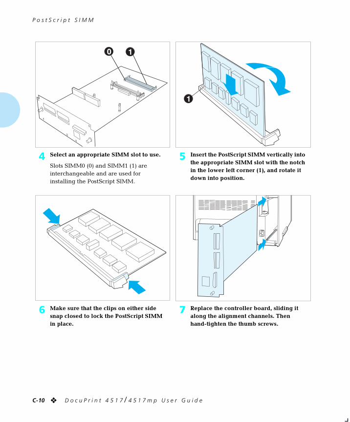
P o s t S c r i p t S I M M
C-10 ❖ D o c u P r i n t 4 5 1 7 / 4 5 1 7 m p U s e r G u i d e
4 Select an appropriate SIMM slot to use.
Slots SIMM0 (0) and SIMM1 (1) are interchangeable and are used for installing the PostScript SIMM.
5 Insert the PostScript SIMM vertically into the appropriate SIMM slot with the notch in the lower left corner (1), and rotate it down into position.
6 Make sure that the clips on either side snap closed to lock the PostScript SIMM in place.
7 Replace the controller board, sliding it along the alignment channels. Then hand-tighten the thumb screws.
chapterc.frm Page 10 Friday, July 11, 1997 9:17 PM
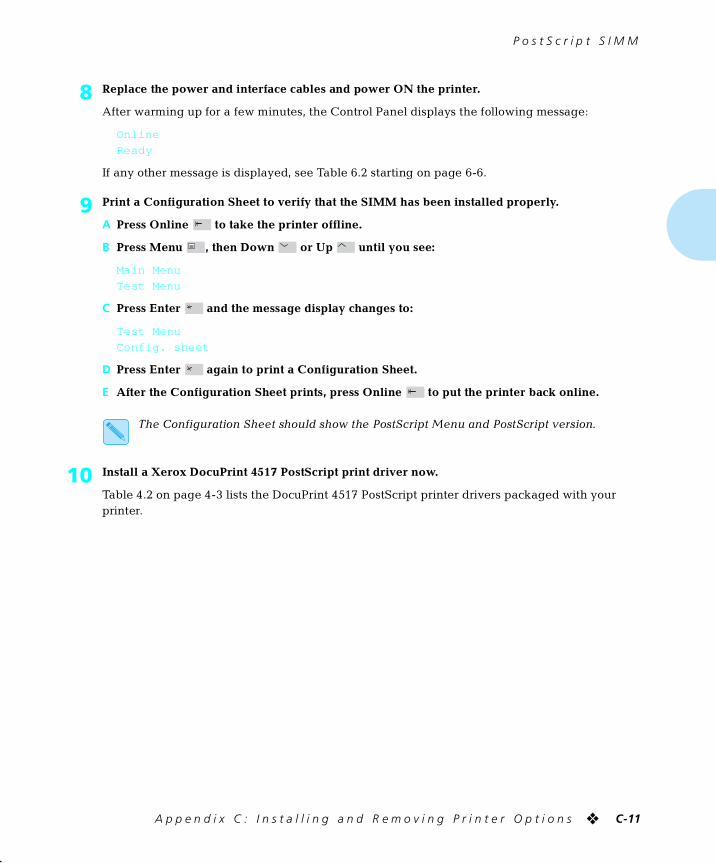
P o s t S c r i p t S I M M
A p p e n d i x C : I n s t a l l i n g a n d R e m o v i n g P r i n t e r O p t i o n s ❖ C-11
8 Replace the power and interface cables and power ON the printer.
After warming up for a few minutes, the Control Panel displays the following message:
Online
Ready
If any other message is displayed, see Table 6.2 starting on page 6-6.
9 Print a Configuration Sheet to verify that the SIMM has been installed properly.
A Press Online to take the printer offline.
B Press Menu , then Down or Up until you see:
Main Menu
Test Menu
C Press Enter and the message display changes to:
Test Menu
Config. sheet
D Press Enter again to print a Configuration Sheet.
E After the Configuration Sheet prints, press Online to put the printer back online.
The Configuration Sheet should show the PostScript Menu and PostScript version.
10 Install a Xerox DocuPrint 4517 PostScript print driver now.
Table 4.2 on page 4-3 lists the DocuPrint 4517 PostScript printer drivers packaged with your printer.
chapterc.frm Page 11 Friday, July 11, 1997 9:17 PM
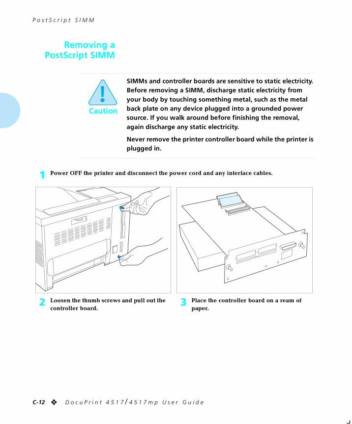
P o s t S c r i p t S I M M
C-12 ❖ D o c u P r i n t 4 5 1 7 / 4 5 1 7 m p U s e r G u i d e
Removing aPostScript SIMM
Caution
SIMMs and controller boards are sensitive to static electricity. Before removing a SIMM, discharge static electricity from your body by touching something metal, such as the metal back plate on any device plugged into a grounded power source. If you walk around before finishing the removal, again discharge any static electricity.
Never remove the printer controller board while the printer is plugged in.
1 Power OFF the printer and disconnect the power cord and any interface cables.
2 Loosen the thumb screws and pull out the controller board.
3 Place the controller board on a ream of paper.
chapterc.frm Page 12 Friday, July 11, 1997 9:17 PM
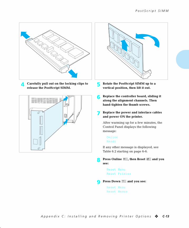
P o s t S c r i p t S I M M
A p p e n d i x C : I n s t a l l i n g a n d R e m o v i n g P r i n t e r O p t i o n s ❖ C-13
4 Carefully pull out on the locking clips to release the PostScript SIMM.
5 Rotate the PostScript SIMM up to a vertical position, then lift it out.
6 Replace the controller board, sliding it along the alignment channels. Then hand-tighten the thumb screws.
7 Replace the power and interface cables and power ON the printer.
After warming up for a few minutes, the Control Panel displays the following message:
Online
Ready
If any other message is displayed, see Table 6.2 starting on page 6-6.
8 Press Online , then Reset and you see:
Reset Menu
Reset Printer
9 Press Down and you see:
Reset Menu
Reset Menus
chapterc.frm Page 13 Friday, July 11, 1997 9:17 PM
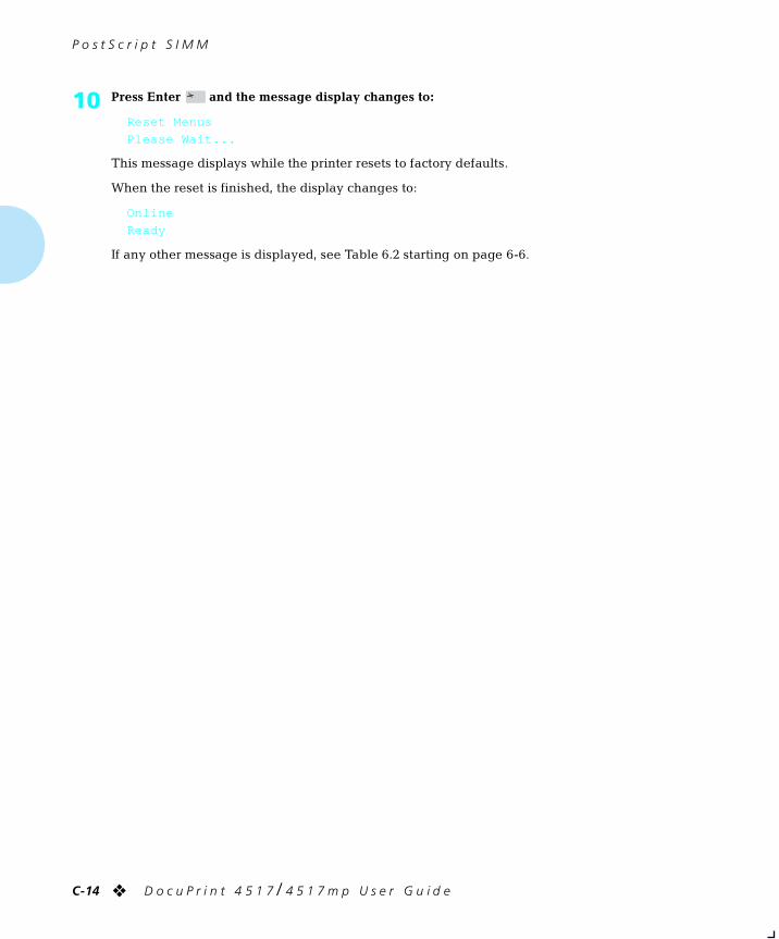
P o s t S c r i p t S I M M
C-14 ❖ D o c u P r i n t 4 5 1 7 / 4 5 1 7 m p U s e r G u i d e
10 Press Enter and the message display changes to:
Reset Menus
Please Wait...
This message displays while the printer resets to factory defaults.
When the reset is finished, the display changes to:
Online
Ready
If any other message is displayed, see Table 6.2 starting on page 6-6.
chapterc.frm Page 14 Friday, July 11, 1997 9:17 PM
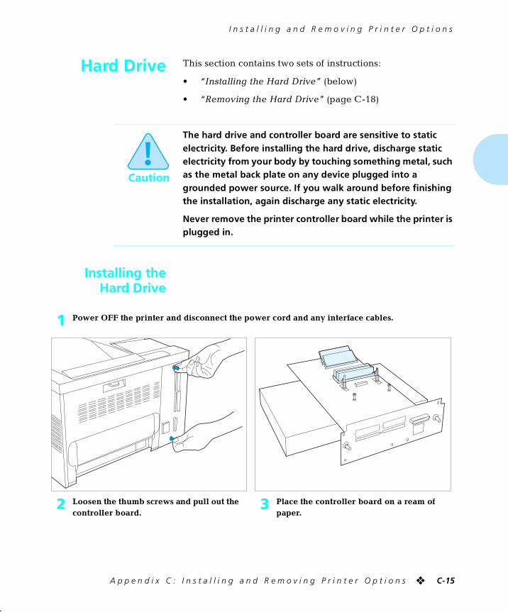
I n s t a l l i n g a n d R e m o v i n g P r i n t e r O p t i o n s
A p p e n d i x C : I n s t a l l i n g a n d R e m o v i n g P r i n t e r O p t i o n s ❖ C-15
Hard Drive This section contains two sets of instructions:
• “Installing the Hard Drive” (below)
• “Removing the Hard Drive” (page C-18)
Installing theHard Drive
Caution
The hard drive and controller board are sensitive to static electricity. Before installing the hard drive, discharge static electricity from your body by touching something metal, such as the metal back plate on any device plugged into a grounded power source. If you walk around before finishing the installation, again discharge any static electricity.
Never remove the printer controller board while the printer is plugged in.
1 Power OFF the printer and disconnect the power cord and any interface cables.
2 Loosen the thumb screws and pull out the controller board.
3 Place the controller board on a ream of paper.
chapterc.frm Page 15 Friday, July 11, 1997 9:17 PM
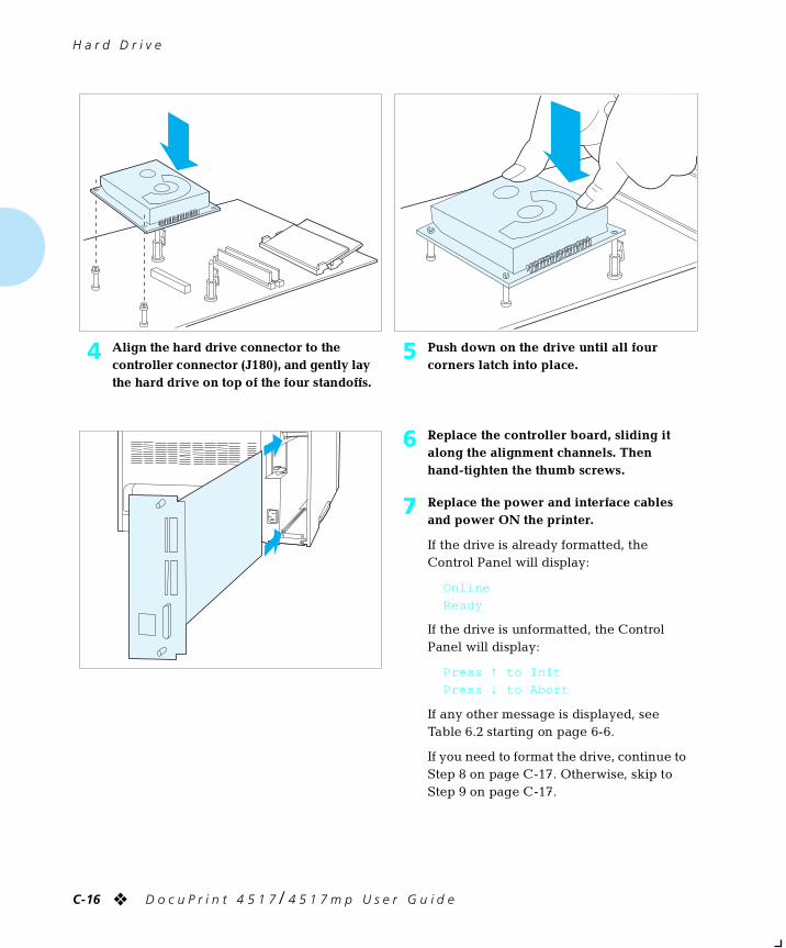
H a r d D r i v e
C-16 ❖ D o c u P r i n t 4 5 1 7 / 4 5 1 7 m p U s e r G u i d e
4 Align the hard drive connector to the controller connector (J180), and gently lay the hard drive on top of the four standoffs.
5 Push down on the drive until all four corners latch into place.
6 Replace the controller board, sliding it along the alignment channels. Then hand-tighten the thumb screws.
7 Replace the power and interface cables and power ON the printer.
If the drive is already formatted, the Control Panel will display:
Online
Ready
If the drive is unformatted, the Control Panel will display:
Press ↑ to Init
Press ↓ to Abort
If any other message is displayed, see Table 6.2 starting on page 6-6.
If you need to format the drive, continue to Step 8 on page C-17. Otherwise, skip to Step 9 on page C-17.
chapterc.frm Page 16 Friday, July 11, 1997 9:17 PM
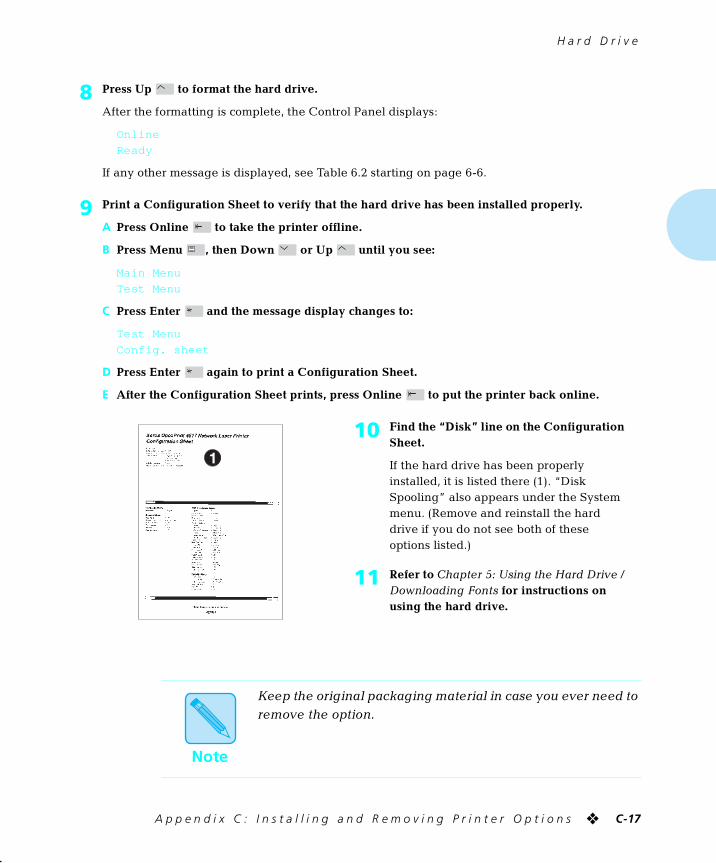
H a r d D r i v e
A p p e n d i x C : I n s t a l l i n g a n d R e m o v i n g P r i n t e r O p t i o n s ❖ C-17
8 Press Up to format the hard drive.
After the formatting is complete, the Control Panel displays:
Online
Ready
If any other message is displayed, see Table 6.2 starting on page 6-6.
9 Print a Configuration Sheet to verify that the hard drive has been installed properly.
A Press Online to take the printer offline.
B Press Menu , then Down or Up until you see:
Main Menu
Test Menu
C Press Enter and the message display changes to:
Test Menu
Config. sheet
D Press Enter again to print a Configuration Sheet.
E After the Configuration Sheet prints, press Online to put the printer back online.
10 Find the “Disk” line on the Configuration Sheet.
If the hard drive has been properly installed, it is listed there (1). “Disk Spooling” also appears under the System menu. (Remove and reinstall the hard drive if you do not see both of these options listed.)
11 Refer to Chapter 5: Using the Hard Drive / Downloading Fonts for instructions on using the hard drive.
Note
Keep the original packaging material in case you ever need to remove the option.
chapterc.frm Page 17 Friday, July 11, 1997 9:17 PM
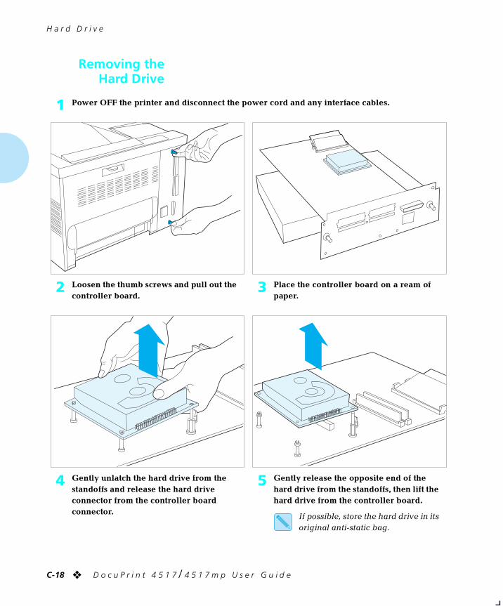
H a r d D r i v e
C-18 ❖ D o c u P r i n t 4 5 1 7 / 4 5 1 7 m p U s e r G u i d e
Removing theHard Drive
1 Power OFF the printer and disconnect the power cord and any interface cables.
2 Loosen the thumb screws and pull out the controller board.
3 Place the controller board on a ream of paper.
4 Gently unlatch the hard drive from the standoffs and release the hard drive connector from the controller board connector.
5 Gently release the opposite end of the hard drive from the standoffs, then lift the hard drive from the controller board.
If possible, store the hard drive in its original anti-static bag.
chapterc.frm Page 18 Friday, July 11, 1997 9:17 PM
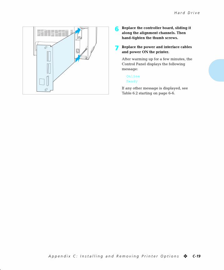
H a r d D r i v e
A p p e n d i x C : I n s t a l l i n g a n d R e m o v i n g P r i n t e r O p t i o n s ❖ C-19
6 Replace the controller board, sliding it along the alignment channels. Then hand-tighten the thumb screws.
7 Replace the power and interface cables and power ON the printer.
After warming up for a few minutes, the Control Panel displays the following message:
Online
Ready
If any other message is displayed, see Table 6.2 starting on page 6-6.
chapterc.frm Page 19 Friday, July 11, 1997 9:17 PM
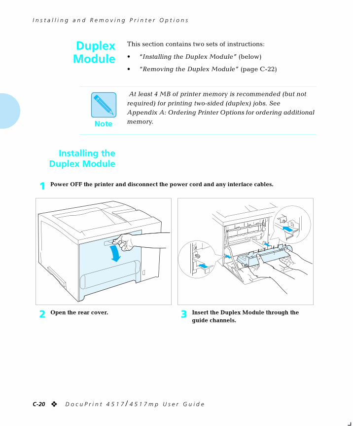
I n s t a l l i n g a n d R e m o v i n g P r i n t e r O p t i o n s
C-20 ❖ D o c u P r i n t 4 5 1 7 / 4 5 1 7 m p U s e r G u i d e
DuplexModule
This section contains two sets of instructions:
• “Installing the Duplex Module” (below)
• “Removing the Duplex Module” (page C-22)
Installing theDuplex Module
Note
At least 4 MB of printer memory is recommended (but not
required) for printing two-sided (duplex) jobs. See Appendix A: Ordering Printer Options for ordering additional memory.
1 Power OFF the printer and disconnect the power cord and any interface cables.
2 Open the rear cover. 3 Insert the Duplex Module through the guide channels.
chapterc.frm Page 20 Friday, July 11, 1997 9:17 PM
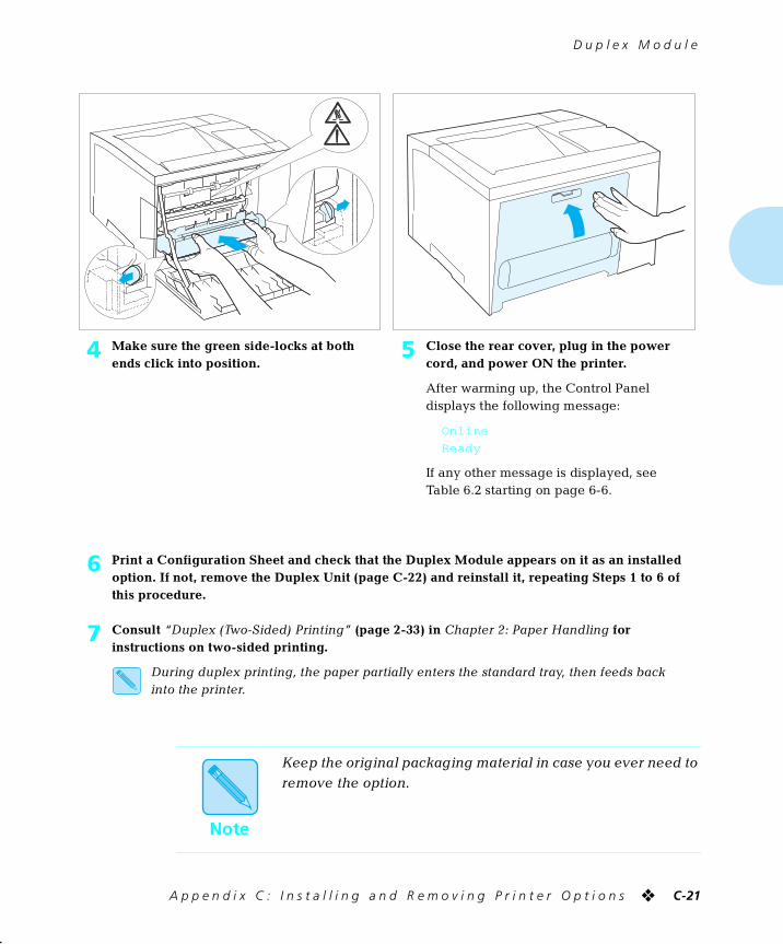
D u p l e x M o d u l e
A p p e n d i x C : I n s t a l l i n g a n d R e m o v i n g P r i n t e r O p t i o n s ❖ C-21
4 Make sure the green side-locks at both ends click into position.
5 Close the rear cover, plug in the power cord, and power ON the printer.
After warming up, the Control Panel displays the following message:
Online
Ready
If any other message is displayed, see Table 6.2 starting on page 6-6.
6 Print a Configuration Sheet and check that the Duplex Module appears on it as an installed option. If not, remove the Duplex Unit (page C-22) and reinstall it, repeating Steps 1 to 6 of this procedure.
7 Consult “Duplex (Two-Sided) Printing” (page 2-33) in Chapter 2: Paper Handling for instructions on two-sided printing.
During duplex printing, the paper partially enters the standard tray, then feeds back into the printer.
Note
Keep the original packaging material in case you ever need to remove the option.
chapterc.frm Page 21 Friday, July 11, 1997 9:19 PM
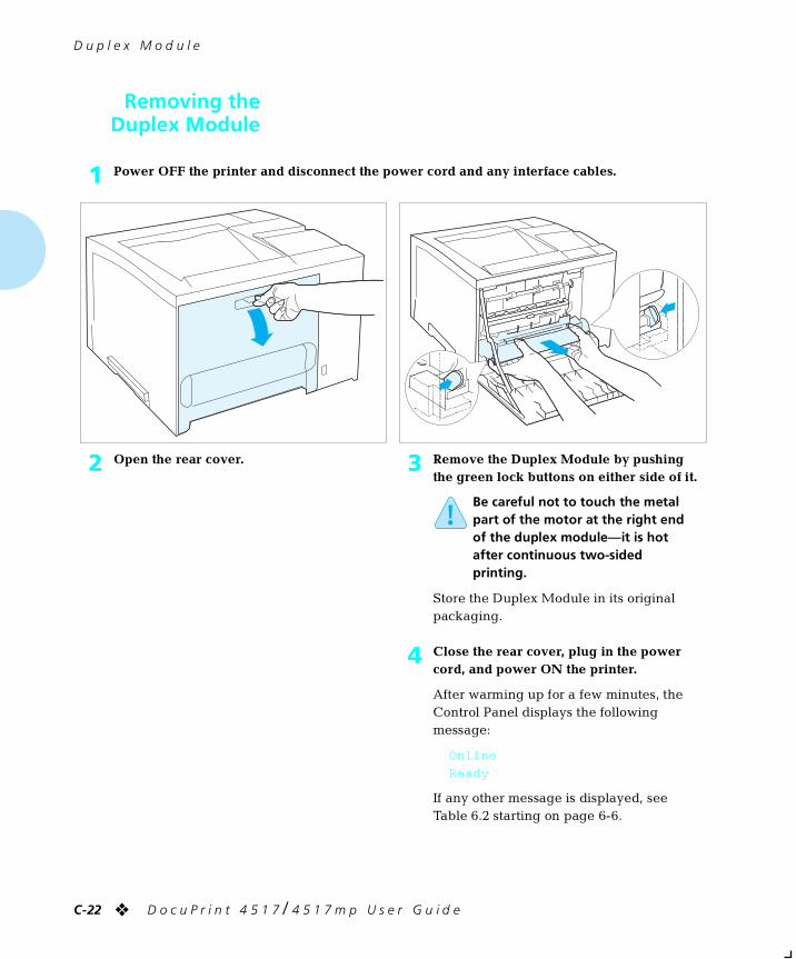
D u p l e x M o d u l e
C-22 ❖ D o c u P r i n t 4 5 1 7 / 4 5 1 7 m p U s e r G u i d e
Removing theDuplex Module
1 Power OFF the printer and disconnect the power cord and any interface cables.
2 Open the rear cover. 3 Remove the Duplex Module by pushing the green lock buttons on either side of it.
Be careful not to touch the metal part of the motor at the right end of the duplex module—it is hot after continuous two-sided printing.
Store the Duplex Module in its original packaging.
4 Close the rear cover, plug in the power cord, and power ON the printer.
After warming up for a few minutes, the Control Panel displays the following message:
Online
Ready
If any other message is displayed, see Table 6.2 starting on page 6-6.
chapterc.frm Page 22 Friday, July 11, 1997 9:19 PM
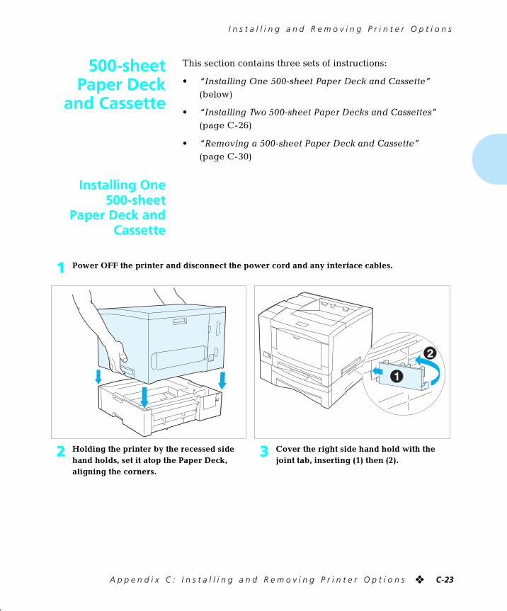
I n s t a l l i n g a n d R e m o v i n g P r i n t e r O p t i o n s
A p p e n d i x C : I n s t a l l i n g a n d R e m o v i n g P r i n t e r O p t i o n s ❖ C-23
500-sheetPaper Deck
and Cassette
This section contains three sets of instructions:
• “Installing One 500-sheet Paper Deck and Cassette” (below)
• “Installing Two 500-sheet Paper Decks and Cassettes” (page C-26)
• “Removing a 500-sheet Paper Deck and Cassette” (page C-30)
Installing One500-sheet
Paper Deck andCassette
1 Power OFF the printer and disconnect the power cord and any interface cables.
2 Holding the printer by the recessed side hand holds, set it atop the Paper Deck, aligning the corners.
3 Cover the right side hand hold with the joint tab, inserting (1) then (2).
chapterc.frm Page 23 Friday, July 11, 1997 9:19 PM
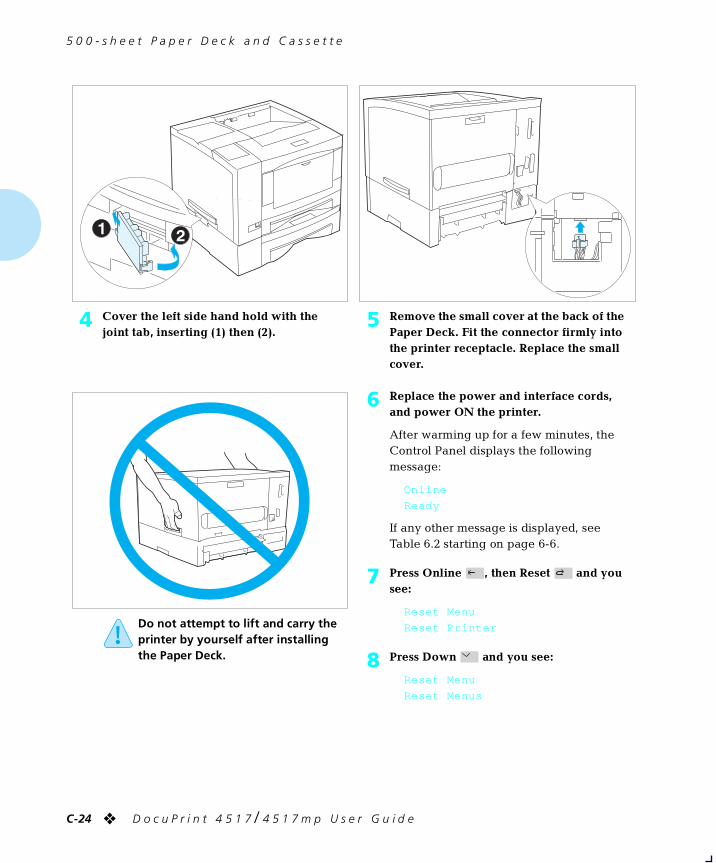
5 0 0 - s h e e t P a p e r D e c k a n d C a s s e t t e
C-24 ❖ D o c u P r i n t 4 5 1 7 / 4 5 1 7 m p U s e r G u i d e
4 Cover the left side hand hold with the joint tab, inserting (1) then (2).
5 Remove the small cover at the back of the Paper Deck. Fit the connector firmly into the printer receptacle. Replace the small cover.
Do not attempt to lift and carry the printer by yourself after installing the Paper Deck.
6 Replace the power and interface cords, and power ON the printer.
After warming up for a few minutes, the Control Panel displays the following message:
Online
Ready
If any other message is displayed, see Table 6.2 starting on page 6-6.
7 Press Online , then Reset and you see:
Reset Menu
Reset Printer
8 Press Down and you see:
Reset Menu
Reset Menus
chapterc.frm Page 24 Friday, July 11, 1997 9:19 PM
5 0 0 - s h e e t P a p e r D e c k a n d C a s s e t t e
A p p e n d i x C : I n s t a l l i n g a n d R e m o v i n g P r i n t e r O p t i o n s ❖ C-25
9 Press Enter and the message display changes to:
Reset Menus
Please Wait...
This message displays while the printer resets the Source Mapping (PCL Menu) settings to include the lower tray just installed.
When the reset is finished, the display changes to:
Online
Ready
If any other message is displayed, see Table 6.2 starting on page 6-6.
To enable automatic tray switching with PostScript jobs, turn Tray Switching in the PostScript menu to a value that includes the newly installed tray.
10 Consult the section “Using the 500-sheet Paper Deck and Cassette” (page 2-12) for instructions on loading paper in the lower tray.
11 Consult the section “Automatic Tray Switching” (page 2-18) for instructions on engaging tray switching between the lower tray and other printer trays.
Note
Keep the original packaging material in case you ever need to remove the option.
chapterc.frm Page 25 Friday, July 11, 1997 9:19 PM
5 0 0 - s h e e t P a p e r D e c k a n d C a s s e t t e
C-26 ❖ D o c u P r i n t 4 5 1 7 / 4 5 1 7 m p U s e r G u i d e
Installing Two500-sheet
Paper Decks andCassettes
1 Power OFF the printer and disconnect the power cord and any interface cables.
2 Holding the top Paper Deck by the recessed side hand holds, set it atop the bottom Paper Deck, aligning the corners.
3 Cover the left side hand hold with the joint tab, inserting (1) then (2).
chapterc.frm Page 26 Friday, July 11, 1997 9:19 PM
5 0 0 - s h e e t P a p e r D e c k a n d C a s s e t t e
A p p e n d i x C : I n s t a l l i n g a n d R e m o v i n g P r i n t e r O p t i o n s ❖ C-27
4 Cover the right side hand hold with the joint tab, inserting (1) then (2).
5 Remove the small cover at the back of the bottom Paper Deck. Fit the connector firmly into the top Paper Deck receptacle. Replace the small cover.
6 Holding the printer by the recessed side hand holds, set it atop the top Paper Deck, aligning the corners.
7 Cover the right side hand hold with the joint tab, inserting (1) then (2).
chapterc.frm Page 27 Friday, July 11, 1997 9:19 PM
5 0 0 - s h e e t P a p e r D e c k a n d C a s s e t t e
C-28 ❖ D o c u P r i n t 4 5 1 7 / 4 5 1 7 m p U s e r G u i d e
8 Cover the left side hand hold with the joint tab, inserting (1) then (2).
9 Remove the small cover at the back of the top Paper Deck. Fit the connector firmly into the printer receptacle. Replace the small cover.
Do not attempt to lift and carry the printer by yourself after installing the Paper Decks.
10 Replace the power and interface cords, and power ON the printer.
After warming up for a few minutes, the Control Panel displays the following message:
Online
Ready
If any other message is displayed, see Table 6.2 starting on page 6-6.
11 Press Online , then Reset and you see:
Reset Menu
Reset Printer
12 Press Down and you see:
Reset Menu
Reset Menus
chapterc.frm Page 28 Friday, July 11, 1997 9:19 PM
5 0 0 - s h e e t P a p e r D e c k a n d C a s s e t t e
A p p e n d i x C : I n s t a l l i n g a n d R e m o v i n g P r i n t e r O p t i o n s ❖ C-29
13 Press Enter and the message display changes to:
Reset Menus
Please Wait...
This message displays while the printer resets the Source Mapping (PCL Menu) settings to include the lower trays just installed.
When the reset is finished, the display changes to:
Online
Ready
If any other message is displayed, see Table 6.2 starting on page 6-6.
To enable automatic tray switching with PostScript jobs, turn Tray Switching in the PostScript menu to a value that includes the newly installed trays.
14 Consult the section “Using the 500-sheet Paper Deck and Cassette” (page 2-12) for instructions on loading paper in the 500-sheet Paper Deck and Cassette (lower tray).
15 Consult the section “Automatic Tray Switching” (page 2-18) for instructions on engaging tray switching between the lower tray and other printer trays.
Note
Keep the original packaging material in case you ever need to remove the option.
chapterc.frm Page 29 Friday, July 11, 1997 9:19 PM
5 0 0 - s h e e t P a p e r D e c k a n d C a s s e t t e
C-30 ❖ D o c u P r i n t 4 5 1 7 / 4 5 1 7 m p U s e r G u i d e
Removing a500-sheet Paper
Deck and Cassette
1 Power OFF the printer and disconnect the power cord and any interface cables.
2 Remove the small cover at the back of the Paper Deck, then unplug the connector from the printer. Replace the small cover.
3 Remove the left joint tab joining the printer to the Paper Deck, removing (1) then (2).
4 Remove the right joint tab joining the printer to the Paper Deck, removing (1) then (2).
5 Holding the printer by the recessed side hand holds, lift it up off the Paper Deck.
chapterc.frm Page 30 Friday, July 11, 1997 9:19 PM
5 0 0 - s h e e t P a p e r D e c k a n d C a s s e t t e
A p p e n d i x C : I n s t a l l i n g a n d R e m o v i n g P r i n t e r O p t i o n s ❖ C-31
6 If two Paper Decks are installed, detach the Paper Decks from each other. Otherwise, continue to Step 7.
A Remove the joint tabs joining the two Paper Decks.
B Disconnect the plug of the bottom Paper Deck from the receptacle of the upper Paper Deck.
Be sure to keep the joint tabs. You will need them to reinstall the Paper Deck(s).
7 Replace the power and interface cords, and power ON the printer.
After warming up for a few minutes, the Control Panel displays the following message:
Online
Ready
If any other message is displayed, see Table 6.2 starting on page 6-6.
8 Press Online , then Reset and you see:
Reset Menu
Reset Printer
9 Press Down and you see:
Reset Menu
Reset Menus
10 Press Enter and the message display changes to:
Reset Menus
Please Wait...
This message displays while the printer resets the Source Mapping (PCL Menu) and Tray Switching (PostScript Menu) settings to factory defaults.
When the reset is finished, the display changes to:
Online
Ready
If any other message is displayed, see Table 6.2 starting on page 6-6.
chapterc.frm Page 31 Friday, July 11, 1997 9:19 PM
I n s t a l l i n g a n d R e m o v i n g P r i n t e r O p t i o n s
C-32 ❖ D o c u P r i n t 4 5 1 7 / 4 5 1 7 m p U s e r G u i d e
2,000-sheetHigh Capacity
Feeder (HCF)
This section contains two sets of instructions:
• “Installing the 2,000-sheet High Capacity Feeder” (below)
• “Removing the 2,000-sheet High Capacity Feeder” (page C-37)
Consult the section “Using the High Capacity Feeder”
(page 2-14) to load paper in the HCF.
Note
The HCF may be installed with or without one optional 500-sheet Paper Deck and Cassette, to increase your paper
input capacity to 2,500 sheets. However, when the HCF is installed with a 500-sheet Paper Deck and Cassette, paper feeding from the HCF is slower.
To install the HCF with a 500-sheet Paper Deck and Cassette,
first install the 500-sheet Paper Deck and Cassette as per the instructions on page C-23, then install the HCF as per the instructions on page C-33.
Note
The documentation that accompanied the HCF contains information on configuring your printer driver and
application to use the HCF.
chapterc.frm Page 32 Friday, July 11, 1997 9:19 PM
2 , 0 0 0 - s h e e t H i g h C a p a c i t y F e e d e r ( H C F )
A p p e n d i x C : I n s t a l l i n g a n d R e m o v i n g P r i n t e r O p t i o n s ❖ C-33
Installing the2,000-sheet HighCapacity Feeder
1 Power OFF the printer and disconnect all cables and cords.
Note: If you have options attached to the printer, such as a Mailbox/Collator, Offset Catch Tray or 500-Sheet Paper Deck, you may need another person to assist you with the installation.
2 Hold the printer with its front facing you and stand in front of the HCF. Align the front right corners of the printer and HCF as you lower the printer onto the HCF.
3 Set the printer down onto the HCF so that the HCF’s pins insert into the bottom of the printer. The front and right sides of the printer should be flush with the front and right sides of the HCF.
If connecting directly to the printer, continue with Step 4.If a 500-Sheet Paper Deck is being installed with the HCF, go to Step 5.
chapterc.frm Page 33 Friday, July 11, 1997 9:19 PM
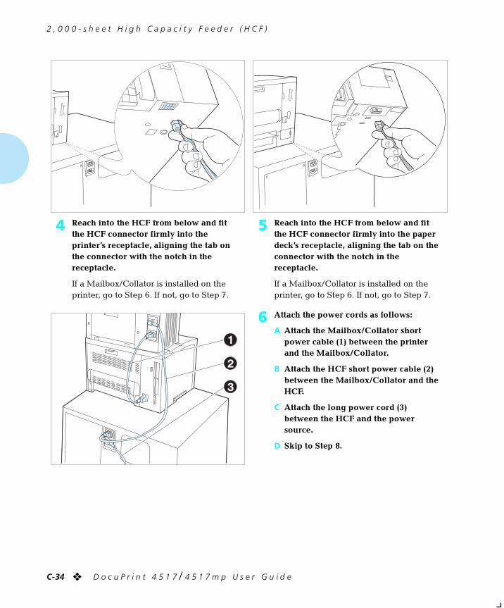
2 , 0 0 0 - s h e e t H i g h C a p a c i t y F e e d e r ( H C F )
C-34 ❖ D o c u P r i n t 4 5 1 7 / 4 5 1 7 m p U s e r G u i d e
4 Reach into the HCF from below and fit the HCF connector firmly into the printer’s receptacle, aligning the tab on the connector with the notch in the receptacle.
If a Mailbox/Collator is installed on the printer, go to Step 6. If not, go to Step 7.
5 Reach into the HCF from below and fit the HCF connector firmly into the paper deck’s receptacle, aligning the tab on the connector with the notch in the receptacle.
If a Mailbox/Collator is installed on the printer, go to Step 6. If not, go to Step 7.
6 Attach the power cords as follows:
A Attach the Mailbox/Collator short power cable (1) between the printer and the Mailbox/Collator.
B Attach the HCF short power cable (2) between the Mailbox/Collator and the HCF.
C Attach the long power cord (3) between the HCF and the power source.
D Skip to Step 8.
chapterc.frm Page 34 Friday, July 11, 1997 9:19 PM
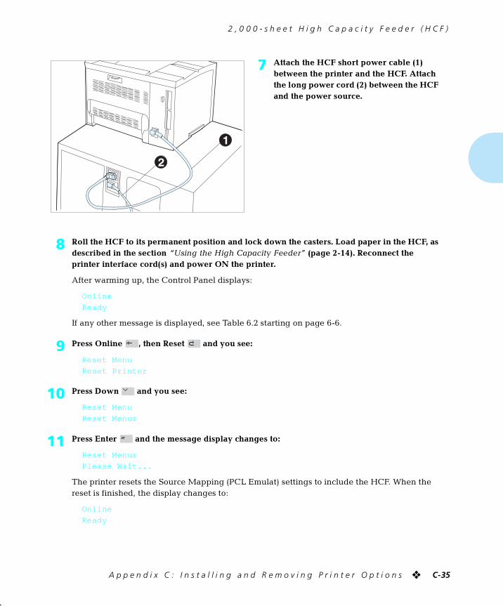
2 , 0 0 0 - s h e e t H i g h C a p a c i t y F e e d e r ( H C F )
A p p e n d i x C : I n s t a l l i n g a n d R e m o v i n g P r i n t e r O p t i o n s ❖ C-35
7 Attach the HCF short power cable (1) between the printer and the HCF. Attach the long power cord (2) between the HCF and the power source.
8 Roll the HCF to its permanent position and lock down the casters. Load paper in the HCF, as described in the section “Using the High Capacity Feeder” (page 2-14). Reconnect the printer interface cord(s) and power ON the printer.
After warming up, the Control Panel displays:
Online
Ready
If any other message is displayed, see Table 6.2 starting on page 6-6.
9 Press Online , then Reset and you see:
Reset Menu
Reset Printer
10 Press Down and you see:
Reset Menu
Reset Menus
11 Press Enter and the message display changes to:
Reset Menus
Please Wait...
The printer resets the Source Mapping (PCL Emulat) settings to include the HCF. When the reset is finished, the display changes to:
Online
Ready
chapterc.frm Page 35 Friday, July 11, 1997 9:19 PM
2 , 0 0 0 - s h e e t H i g h C a p a c i t y F e e d e r ( H C F )
C-36 ❖ D o c u P r i n t 4 5 1 7 / 4 5 1 7 m p U s e r G u i d e
12 Print a Configuration Sheet and check that the HCF and 500-sheet Paper Deck and Cassette (if installed) appear as “Lower 1 Tray” and/or “Lower 2 Tray” under “Installed Options.” If not, power OFF the printer and recheck the HCF connector, the 500-sheet Paper Deck and Cassette connector (if installed) and power cables.
Note
To enable automatic tray switching with PostScript jobs, turn Tray Switching in the PostScript menu to a value that includes the newly installed tray, such as “Lower 1-Main.” Refer to the
section “Automatic Tray Switching” (page 2-18).
Note
Keep the original packaging material in case you ever need to
remove the option.
Note
The “Installation Setup Guide” that accompanied the HCF tells how to configure your driver and applications to use the HCF.
chapterc.frm Page 36 Friday, July 11, 1997 9:19 PM
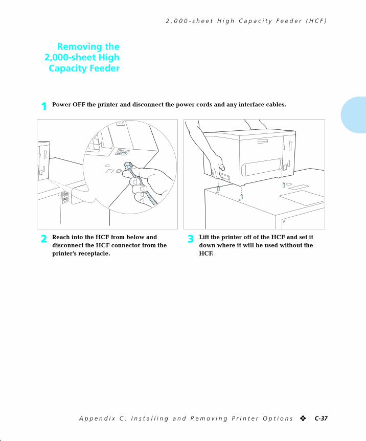
2 , 0 0 0 - s h e e t H i g h C a p a c i t y F e e d e r ( H C F )
A p p e n d i x C : I n s t a l l i n g a n d R e m o v i n g P r i n t e r O p t i o n s ❖ C-37
Removing the2,000-sheet HighCapacity Feeder
1 Power OFF the printer and disconnect the power cords and any interface cables.
2 Reach into the HCF from below and disconnect the HCF connector from the printer’s receptacle.
3 Lift the printer off of the HCF and set it down where it will be used without the HCF.
chapterc.frm Page 37 Friday, July 11, 1997 9:19 PM
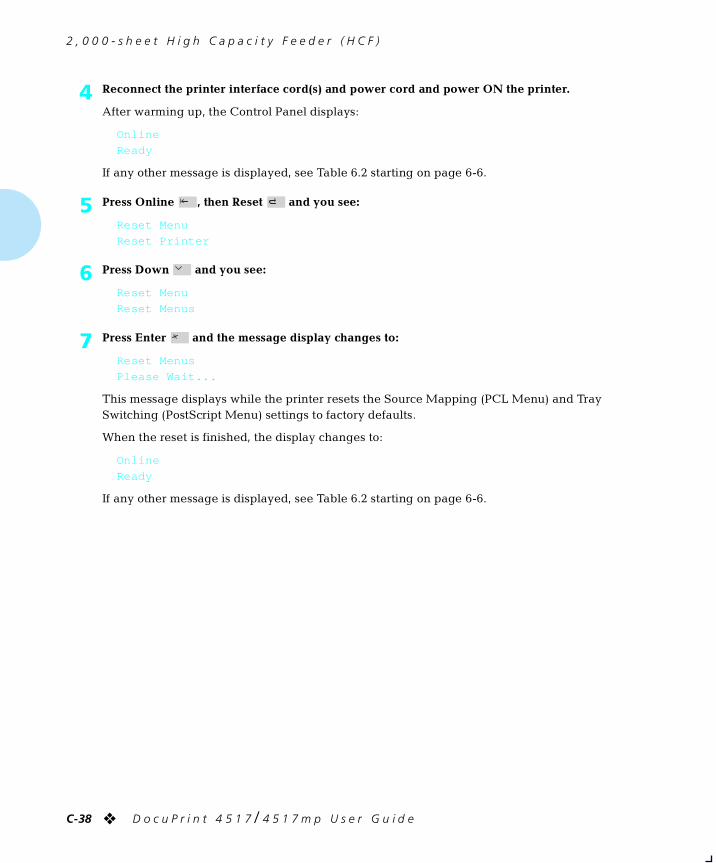
2 , 0 0 0 - s h e e t H i g h C a p a c i t y F e e d e r ( H C F )
C-38 ❖ D o c u P r i n t 4 5 1 7 / 4 5 1 7 m p U s e r G u i d e
4 Reconnect the printer interface cord(s) and power cord and power ON the printer.
After warming up, the Control Panel displays:
Online
Ready
If any other message is displayed, see Table 6.2 starting on page 6-6.
5 Press Online , then Reset and you see:
Reset Menu
Reset Printer
6 Press Down and you see:
Reset Menu
Reset Menus
7 Press Enter and the message display changes to:
Reset Menus
Please Wait...
This message displays while the printer resets the Source Mapping (PCL Menu) and Tray Switching (PostScript Menu) settings to factory defaults.
When the reset is finished, the display changes to:
Online
Ready
If any other message is displayed, see Table 6.2 starting on page 6-6.
chapterc.frm Page 38 Friday, July 11, 1997 9:19 PM
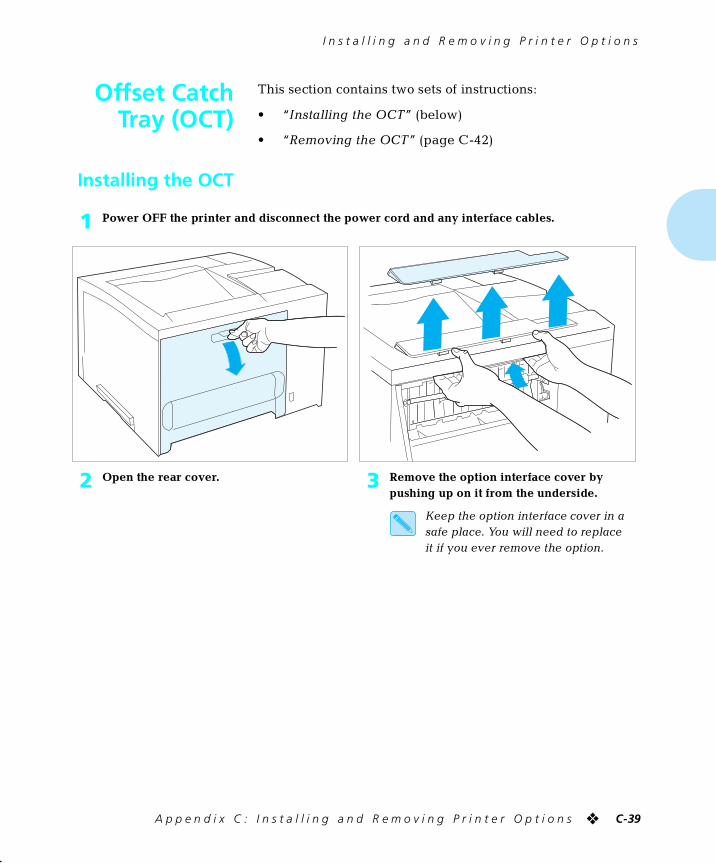
I n s t a l l i n g a n d R e m o v i n g P r i n t e r O p t i o n s
A p p e n d i x C : I n s t a l l i n g a n d R e m o v i n g P r i n t e r O p t i o n s ❖ C-39
Offset CatchTray (OCT)
This section contains two sets of instructions:
• “Installing the OCT” (below)
• “Removing the OCT” (page C-42)
Installing the OCT
1 Power OFF the printer and disconnect the power cord and any interface cables.
2 Open the rear cover. 3 Remove the option interface cover by pushing up on it from the underside.
Keep the option interface cover in a safe place. You will need to replace it if you ever remove the option.
chapterc.frm Page 39 Friday, July 11, 1997 9:19 PM
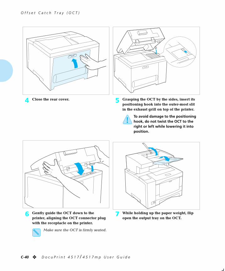
O f f s e t C a t c h T r a y ( O C T )
C-40 ❖ D o c u P r i n t 4 5 1 7 / 4 5 1 7 m p U s e r G u i d e
4 Close the rear cover. 5 Grasping the OCT by the sides, insert its positioning hook into the outer-most slit in the exhaust grill on top of the printer.
To avoid damage to the positioning hook, do not twist the OCT to the right or left while lowering it into position.
6 Gently guide the OCT down to the printer, aligning the OCT connector plug with the receptacle on the printer.
Make sure the OCT is firmly seated.
7 While holding up the paper weight, flip open the output tray on the OCT.
chapterc.frm Page 40 Friday, July 11, 1997 9:19 PM
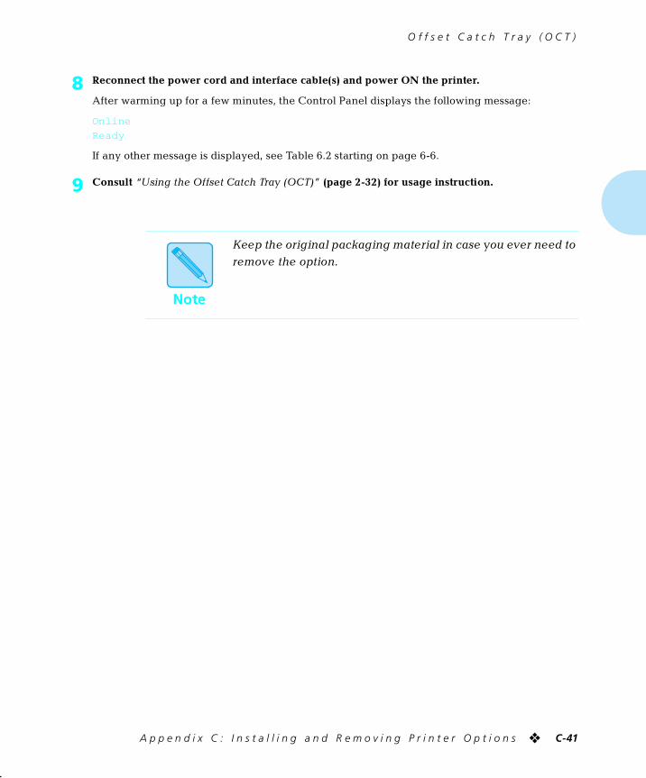
O f f s e t C a t c h T r a y ( O C T )
A p p e n d i x C : I n s t a l l i n g a n d R e m o v i n g P r i n t e r O p t i o n s ❖ C-41
8 Reconnect the power cord and interface cable(s) and power ON the printer.
After warming up for a few minutes, the Control Panel displays the following message:
Online
Ready
If any other message is displayed, see Table 6.2 starting on page 6-6.
9 Consult “Using the Offset Catch Tray (OCT)” (page 2-32) for usage instruction.
Note
Keep the original packaging material in case you ever need to
remove the option.
chapterc.frm Page 41 Friday, July 11, 1997 9:25 PM
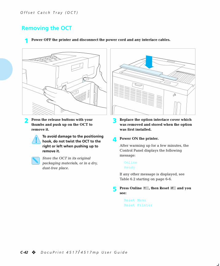
O f f s e t C a t c h T r a y ( O C T )
C-42 ❖ D o c u P r i n t 4 5 1 7 / 4 5 1 7 m p U s e r G u i d e
Removing the OCT
1 Power OFF the printer and disconnect the power cord and any interface cables.
2 Press the release buttons with your thumbs and push up on the OCT to remove it.
To avoid damage to the positioning hook, do not twist the OCT to the right or left when pushing up to remove it.
Store the OCT in its original packaging materials, or in a dry, dust-free place.
3 Replace the option interface cover which was removed and stored when the option was first installed.
4 Power ON the printer.
After warming up for a few minutes, the Control Panel displays the following message:
Online
Ready
If any other message is displayed, see Table 6.2 starting on page 6-6.
5 Press Online , then Reset and you see:
Reset Menu
Reset Printer
chapterc.frm Page 42 Friday, July 11, 1997 9:25 PM
O f f s e t C a t c h T r a y ( O C T )
A p p e n d i x C : I n s t a l l i n g a n d R e m o v i n g P r i n t e r O p t i o n s ❖ C-43
6 Press Down and you see:
Reset Menu
Reset Menus
7 Press Enter and the message display changes to:
Reset Menus
Please Wait...
This message displays while the printer changes the default Output Bin setting to Standard.
When the reset is finished, the display changes to:
Online
Ready
If any other message is displayed, see Table 6.2 starting on page 6-6.
chapterc.frm Page 43 Friday, July 11, 1997 9:25 PM

I n s t a l l i n g a n d R e m o v i n g P r i n t e r O p t i o n s
C-44 ❖ D o c u P r i n t 4 5 1 7 / 4 5 1 7 m p U s e r G u i d e
Mailbox/Collator
This section contains two sets of instructions:
• “Installing the Mailbox/Collator” (below)
• “Removing the Mailbox/Collator” (page C-47)
Installing theMailbox/Collator
Note
Refer to the section “Using the Mailbox/Collator” (page 2-24)
for usage instructions. Also, the Mailbox/Collator User Guide that came with the Mailbox/Collator contains more detailed information about configuring and using the Mailbox/
Collator.
1 Power OFF the printer and disconnect the power cord.
2 Open the rear cover. 3 Remove the option interface cover by feeling for its tabs from the underside and pushing up on them. (This may require some force.) Then close the rear cover.
Keep the option interface cover in a safe place. You will need to replace it if you ever remove the option.
chapterc.frm Page 44 Friday, July 11, 1997 9:25 PM
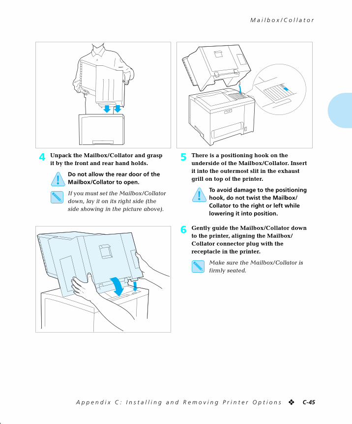
M a i l b o x / C o l l a t o r
A p p e n d i x C : I n s t a l l i n g a n d R e m o v i n g P r i n t e r O p t i o n s ❖ C-45
4 Unpack the Mailbox/Collator and grasp it by the front and rear hand holds.
Do not allow the rear door of the Mailbox/Collator to open.
If you must set the Mailbox/Collator down, lay it on its right side (the side showing in the picture above).
5 There is a positioning hook on the underside of the Mailbox/Collator. Insert it into the outermost slit in the exhaust grill on top of the printer.
To avoid damage to the positioning hook, do not twist the Mailbox/Collator to the right or left while lowering it into position.
6 Gently guide the Mailbox/Collator down to the printer, aligning the Mailbox/Collator connector plug with the receptacle in the printer.
Make sure the Mailbox/Collator is firmly seated.
chapterc.frm Page 45 Friday, July 11, 1997 9:25 PM
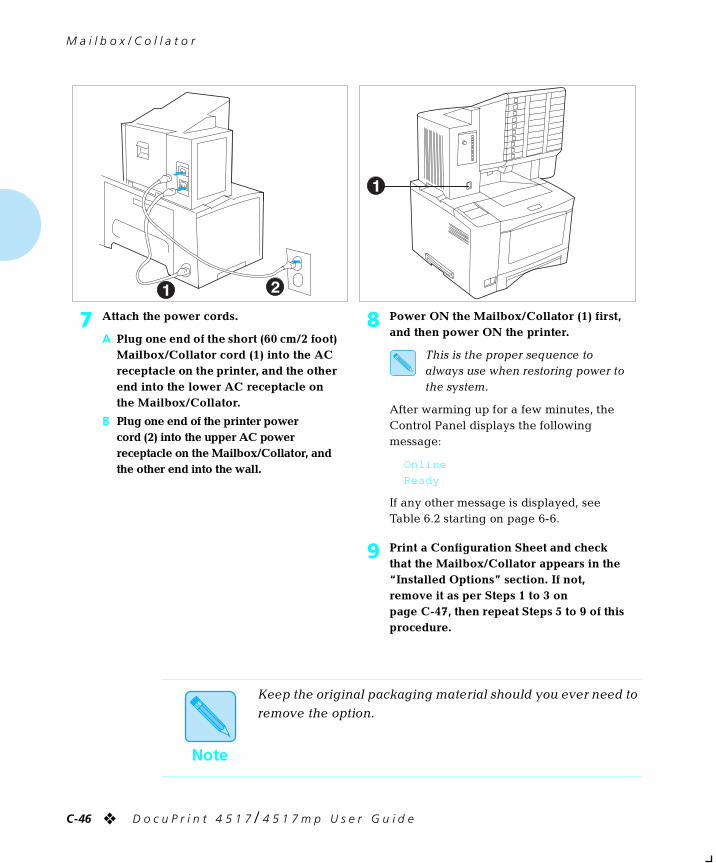
M a i l b o x / C o l l a t o r
C-46 ❖ D o c u P r i n t 4 5 1 7 / 4 5 1 7 m p U s e r G u i d e
7 Attach the power cords.
A Plug one end of the short (60 cm/2 foot) Mailbox/Collator cord (1) into the AC receptacle on the printer, and the other end into the lower AC receptacle on the Mailbox/Collator.
B Plug one end of the printer power cord (2) into the upper AC power receptacle on the Mailbox/Collator, and the other end into the wall.
8 Power ON the Mailbox/Collator (1) first, and then power ON the printer.
This is the proper sequence to always use when restoring power to the system.
After warming up for a few minutes, the Control Panel displays the following message:
Online
Ready
If any other message is displayed, see Table 6.2 starting on page 6-6.
9 Print a Configuration Sheet and check that the Mailbox/Collator appears in the “Installed Options” section. If not, remove it as per Steps 1 to 3 on page C-47, then repeat Steps 5 to 9 of this procedure.
Note
Keep the original packaging material should you ever need to
remove the option.
chapterc.frm Page 46 Friday, July 11, 1997 9:25 PM
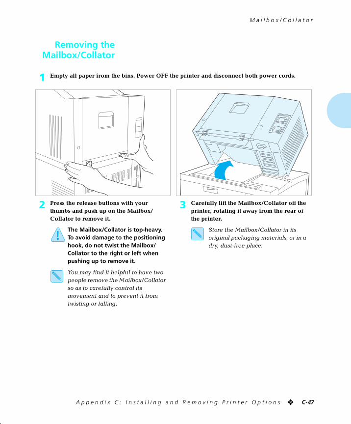
M a i l b o x / C o l l a t o r
A p p e n d i x C : I n s t a l l i n g a n d R e m o v i n g P r i n t e r O p t i o n s ❖ C-47
Removing theMailbox/Collator
1 Empty all paper from the bins. Power OFF the printer and disconnect both power cords.
2 Press the release buttons with your thumbs and push up on the Mailbox/Collator to remove it.
The Mailbox/Collator is top-heavy. To avoid damage to the positioning hook, do not twist the Mailbox/Collator to the right or left when pushing up to remove it.
You may find it helpful to have two people remove the Mailbox/Collator so as to carefully control its movement and to prevent it from twisting or falling.
3 Carefully lift the Mailbox/Collator off the printer, rotating it away from the rear of the printer.
Store the Mailbox/Collator in its original packaging materials, or in a dry, dust-free place.
chapterc.frm Page 47 Friday, July 11, 1997 9:25 PM
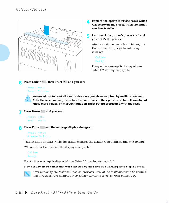
M a i l b o x / C o l l a t o r
C-48 ❖ D o c u P r i n t 4 5 1 7 / 4 5 1 7 m p U s e r G u i d e
4 Replace the option interface cover which was removed and stored when the option was first installed.
5 Reconnect the printer’s power cord and power ON the printer.
After warming up for a few minutes, the Control Panel displays the following message:
Online
Ready
If any other message is displayed, see Table 6.2 starting on page 6-6.
6 Press Online , then Reset and you see:
Reset Menu
Reset Printer
You are about to reset all menu values, not just those required by mailbox removal. After the reset you may need to set menu values to their previous values. If you do not know these values, print a Configuration Sheet before proceeding with the reset.
7 Press Down and you see:
Reset Menu
Reset Menus
8 Press Enter and the message display changes to:
Reset Menus
Please Wait...
This message displays while the printer changes the default Output Bin setting to Standard.
When the reset is finished, the display changes to:
Online
Ready
If any other message is displayed, see Table 6.2 starting on page 6-6.
Now set any menu values that were affected by the reset (see warning after Step 6 above).
After removing the Mailbox/Collator, previous users of the Mailbox should be notified that they need to reconfigure their printer drivers to select another output tray.
chapterc.frm Page 48 Friday, July 11, 1997 9:25 PM
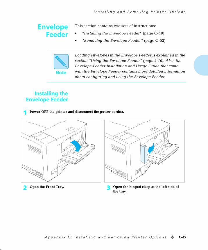
I n s t a l l i n g a n d R e m o v i n g P r i n t e r O p t i o n s
A p p e n d i x C : I n s t a l l i n g a n d R e m o v i n g P r i n t e r O p t i o n s ❖ C-49
EnvelopeFeeder
This section contains two sets of instructions:
• “Installing the Envelope Feeder” (page C-49)
• “Removing the Envelope Feeder” (page C-52)
Installing theEnvelope Feeder
Note
Loading envelopes in the Envelope Feeder is explained in the
section “Using the Envelope Feeder” (page 2-16). Also, the Envelope Feeder Installation and Usage Guide that came with the Envelope Feeder contains more detailed information
about configuring and using the Envelope Feeder.
1 Power OFF the printer and disconnect the power cord(s).
2 Open the Front Tray. 3 Open the hinged clasp at the left side of the tray.
chapterc.frm Page 49 Friday, July 11, 1997 9:25 PM
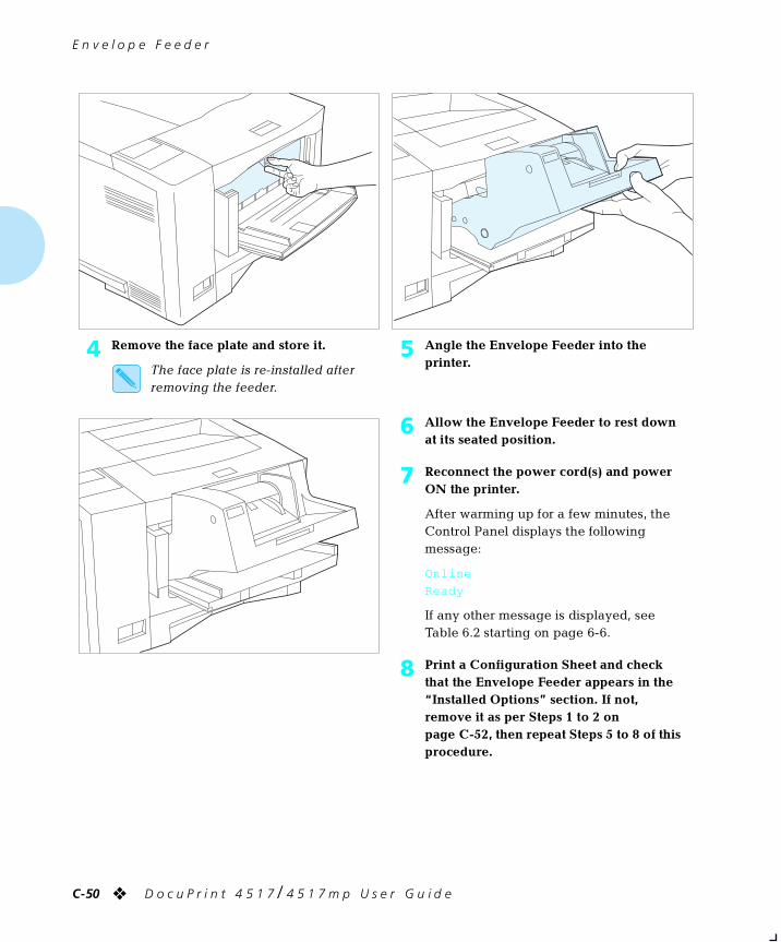
E n v e l o p e F e e d e r
C-50 ❖ D o c u P r i n t 4 5 1 7 / 4 5 1 7 m p U s e r G u i d e
4 Remove the face plate and store it.
The face plate is re-installed after removing the feeder.
5 Angle the Envelope Feeder into the printer.
6 Allow the Envelope Feeder to rest down at its seated position.
7 Reconnect the power cord(s) and power ON the printer.
After warming up for a few minutes, the Control Panel displays the following message:
Online
Ready
If any other message is displayed, see Table 6.2 starting on page 6-6.
8 Print a Configuration Sheet and check that the Envelope Feeder appears in the “Installed Options” section. If not, remove it as per Steps 1 to 2 on page C-52, then repeat Steps 5 to 8 of this procedure.
chapterc.frm Page 50 Friday, July 11, 1997 9:25 PM
E n v e l o p e F e e d e r
A p p e n d i x C : I n s t a l l i n g a n d R e m o v i n g P r i n t e r O p t i o n s ❖ C-51
9 Press Online , then Reset and you see:
Reset Menu
Reset Printer
10 Press Down and you see:
Reset Menu
Reset Menus
11 Press Enter and the message display changes to:
Reset Menus
Please Wait...
This message displays while the printer resets the Source Mapping (PCL Menu) settings to factory defaults, including the Envelope Feeder.
When the reset is finished, the display changes to:
Online
Env Feeder Empty
If any other message is displayed, see Table 6.2 starting on page 6-6.
12 Set the Envelope Feeder size to the size of envelopes you will be loading into the feeder:
A Press Online to take the printer offline.
B Press Menu .
C Press Down until PCL Emulat. Menu (or PostScript Menu) is displayed, then press Enter .
D Press Down until Env Feeder Size is displayed, then press Enter .
E Press Down until your envelope size is displayed, then press Enter .
F After the printer finishes displaying *saved* press Online to bring the printer online.
13 Load envelopes as per the instructions in the section “Using the Envelope Feeder” (page 2-16). For information on configuring your printer driver or application to use the Envelope Feeder, refer to the Installation and Usage Guide that came with the Envelope Feeder.
Note
Keep the original packaging material in case you ever need to remove the option.
chapterc.frm Page 51 Friday, July 11, 1997 9:25 PM
E n v e l o p e F e e d e r
C-52 ❖ D o c u P r i n t 4 5 1 7 / 4 5 1 7 m p U s e r G u i d e
Removing theEnvelope Feeder
1 Power OFF the printer and disconnect the power cord(s).
2 Lift the Envelope Feeder up and out from the printer.
Store the Envelope Feeder in its original packaging materials, or in a dry, dust-free place.
3 Re-attach the face plate that was removed when the Envelope Feeder was installed.
4 Close the hinged clasp at the left side of the Front Tray.
Close the Front Tray if not needed.
5 Reconnect the power cord(s) and power ON the printer.
After warming up for a few minutes, the Control Panel displays the following message:
Online
Ready
If any other message is displayed, see Table 6.2 starting on page 6-6.
chapterc.frm Page 52 Friday, July 11, 1997 9:25 PM
E n v e l o p e F e e d e r
A p p e n d i x C : I n s t a l l i n g a n d R e m o v i n g P r i n t e r O p t i o n s ❖ C-53
6 Press Online , then Reset and you see:
Reset Menu
Reset Printer
7 Press Down and you see:
Reset Menu
Reset Menus
8 Press Enter and the message display changes to:
Reset Menus
Please Wait...
This message displays while the printer resets the Source Mapping (PCL Menu) settings to factory defaults.
When the reset is finished, the display changes to:
Online
Ready
If any other message is displayed, see Table 6.2 starting on page 6-6.
chapterc.frm Page 53 Friday, July 11, 1997 9:25 PM
I n s t a l l i n g a n d R e m o v i n g P r i n t e r O p t i o n s
C-54 ❖ D o c u P r i n t 4 5 1 7 / 4 5 1 7 m p U s e r G u i d e
Font Cards andMacro Cards
Follow the instructions below to either install or remove font
cards or macro cards. Up to two cards can be installed, in any combination.
1 Press Online to take the printer offline.
2 Insert or remove the card.
If removing a card, skip to Step 5.
3 Press Online to put the printer back online.
4 To verify that the printer recognizes the card as installed, print a Configuration Sheet.
A Press Online to take the printer offline.
B Press Menu , then Down or Up until you see:
Main Menu
Test Menu
C Press Enter and the message display changes to:
Test Menu
Config. sheet
D Press Enter again to print a Configuration Sheet.
You should see the card listed under “Installed options.”
5 Press Online to put the printer back online.
chapterc.frm Page 54 Friday, July 11, 1997 9:25 PM
I n s t a l l i n g a n d R e m o v i n g P r i n t e r O p t i o n s
A p p e n d i x C : I n s t a l l i n g a n d R e m o v i n g P r i n t e r O p t i o n s ❖ C-55
XeroxNetwork
Interface Card(XNIC)
This section contains two sets of instructions:
• “Installing the XNIC” (page C-56)
• “Removing the XNIC” (page C-60)
These instructions apply to Ethernet (XNIC-E’NET), Token Ring (XNIC-T’RING) and LocalTalk (XNIC-L’TALK).
Caution
The XNIC and controller board are sensitive to static electricity. Before installing the XNIC, discharge static electricity from your body by touching something metal, such as the metal back plate on any device plugged into a grounded power source. If you walk around before finishing the installation, again discharge any static electricity.
Never remove the printer controller board while the printer is plugged in.
Note
The printer is capable of supporting two XNICs; however, do not install two of the same XNICs in the printer.
chapterc.frm Page 55 Friday, July 11, 1997 9:25 PM
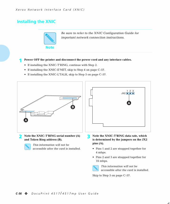
X e r o x N e t w o r k I n t e r f a c e C a r d ( X N I C )
C-56 ❖ D o c u P r i n t 4 5 1 7 / 4 5 1 7 m p U s e r G u i d e
Installing the XNIC
Note
Be sure to refer to the XNIC Configuration Guide for important network connection instructions.
1 Power OFF the printer and disconnect the power cord and any interface cables.
• If installing the XNIC-T’RING, continue with Step 2.
• If installing the XNIC-E’NET, skip to Step 4 on page C-57.
• If installing the XNIC-L’TALK, skip to Step 5 on page C-57.
2 Note the XNIC-T’RING serial number (A) and Token Ring address (B).
This information will not be accessible after the card is installed.
3 Note the XNIC-T’RING data rate, which is determined by the jumpers on the JX2 pins (A).
• Pins 1 and 2 are strapped together for 4 mbps.
• Pins 2 and 3 are strapped together for 16 mbps.
This information will not be accessible after the card is installed.
Skip to Step 5 on page C-57.
chapterc.frm Page 56 Friday, July 11, 1997 9:25 PM
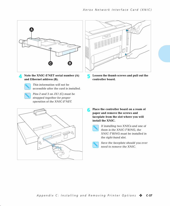
X e r o x N e t w o r k I n t e r f a c e C a r d ( X N I C )
A p p e n d i x C : I n s t a l l i n g a n d R e m o v i n g P r i n t e r O p t i o n s ❖ C-57
4 Note the XNIC-E’NET serial number (A) and Ethernet address (B).
This information will not be accessible after the card is installed.
Pins 2 and 3 on JX1 (C) must be strapped together for proper operation of the XNIC-E’NET.
5 Loosen the thumb screws and pull out the controller board.
6 Place the controller board on a ream of paper and remove the screws and faceplate from the slot where you will install the XNIC.
If installing two XNICs and one of them is the XNIC-T’RING, the XNIC-T’RING must be installed in the right-hand slot.
Save the faceplate should you ever need to remove the XNIC.
chapterc.frm Page 57 Friday, July 11, 1997 9:25 PM
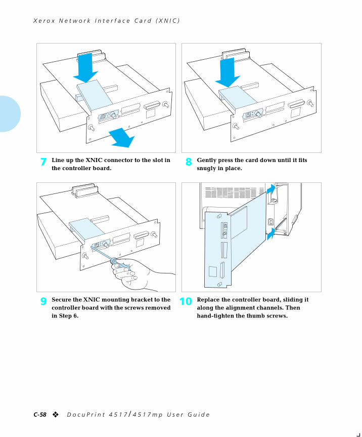
X e r o x N e t w o r k I n t e r f a c e C a r d ( X N I C )
C-58 ❖ D o c u P r i n t 4 5 1 7 / 4 5 1 7 m p U s e r G u i d e
7 Line up the XNIC connector to the slot in the controller board.
8 Gently press the card down until it fits snugly in place.
9 Secure the XNIC mounting bracket to the controller board with the screws removed in Step 6.
10 Replace the controller board, sliding it along the alignment channels. Then hand-tighten the thumb screws.
chapterc.frm Page 58 Friday, July 11, 1997 9:25 PM
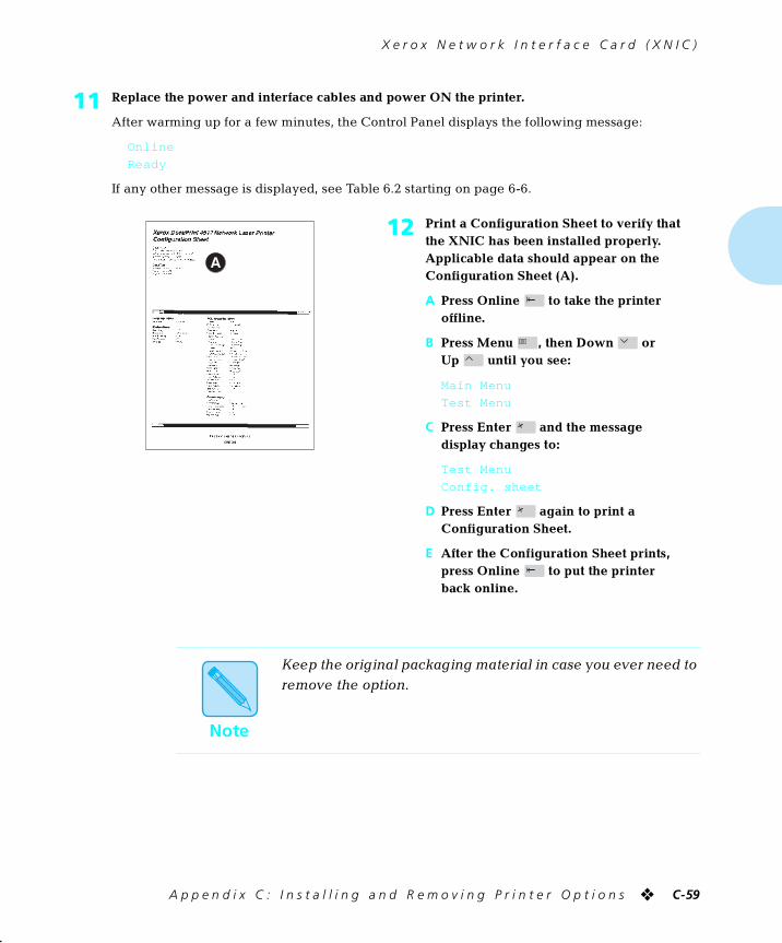
X e r o x N e t w o r k I n t e r f a c e C a r d ( X N I C )
A p p e n d i x C : I n s t a l l i n g a n d R e m o v i n g P r i n t e r O p t i o n s ❖ C-59
11 Replace the power and interface cables and power ON the printer.
After warming up for a few minutes, the Control Panel displays the following message:
Online
Ready
If any other message is displayed, see Table 6.2 starting on page 6-6.
12 Print a Configuration Sheet to verify that the XNIC has been installed properly. Applicable data should appear on the Configuration Sheet (A).
A Press Online to take the printer offline.
B Press Menu , then Down or Up until you see:
Main Menu
Test Menu
C Press Enter and the message display changes to:
Test Menu
Config. sheet
D Press Enter again to print a Configuration Sheet.
E After the Configuration Sheet prints, press Online to put the printer back online.
Note
Keep the original packaging material in case you ever need to remove the option.
chapterc.frm Page 59 Friday, July 11, 1997 9:25 PM
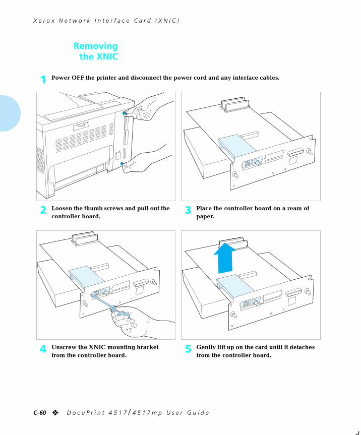
X e r o x N e t w o r k I n t e r f a c e C a r d ( X N I C )
C-60 ❖ D o c u P r i n t 4 5 1 7 / 4 5 1 7 m p U s e r G u i d e
Removingthe XNIC
1 Power OFF the printer and disconnect the power cord and any interface cables.
2 Loosen the thumb screws and pull out the controller board.
3 Place the controller board on a ream of paper.
4 Unscrew the XNIC mounting bracket from the controller board.
5 Gently lift up on the card until it detaches from the controller board.
chapterc.frm Page 60 Friday, July 11, 1997 9:25 PM
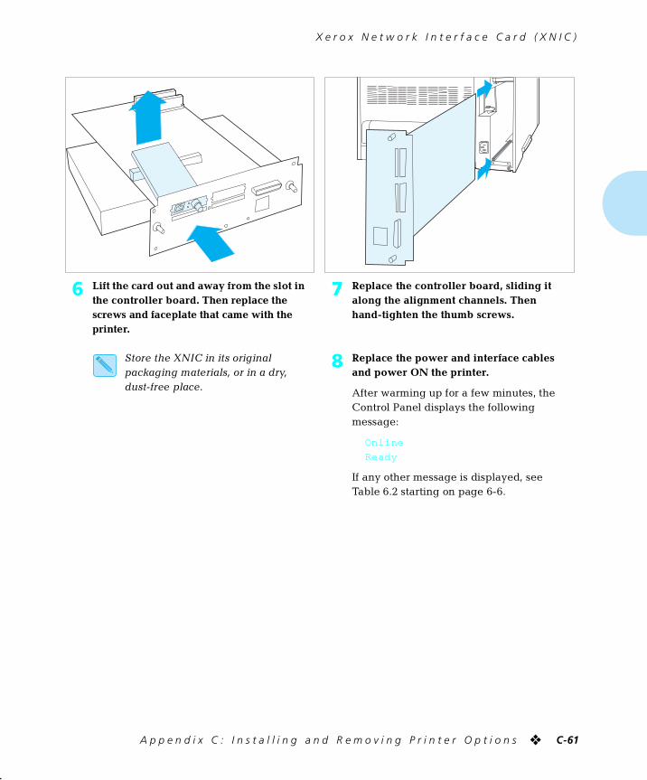
X e r o x N e t w o r k I n t e r f a c e C a r d ( X N I C )
A p p e n d i x C : I n s t a l l i n g a n d R e m o v i n g P r i n t e r O p t i o n s ❖ C-61
6 Lift the card out and away from the slot in the controller board. Then replace the screws and faceplate that came with the printer.
7 Replace the controller board, sliding it along the alignment channels. Then hand-tighten the thumb screws.
Store the XNIC in its original packaging materials, or in a dry, dust-free place.
8 Replace the power and interface cables and power ON the printer.
After warming up for a few minutes, the Control Panel displays the following message:
Online
Ready
If any other message is displayed, see Table 6.2 starting on page 6-6.
chapterc.frm Page 61 Friday, July 11, 1997 9:25 PM

C-62 ❖ D o c u P r i n t 4 5 1 7 / 4 5 1 7 m p U s e r G u i d e
chapterc.frm Page 62 Friday, July 11, 1997 9:25 PM
Appendix D
A p p e n d i x D : C o n t r o l P a n e l O p t i o n s ❖ D-1
Control Panel Options AppendixD
chapterd.frm Page 1 Friday, July 11, 1997 10:19 PM
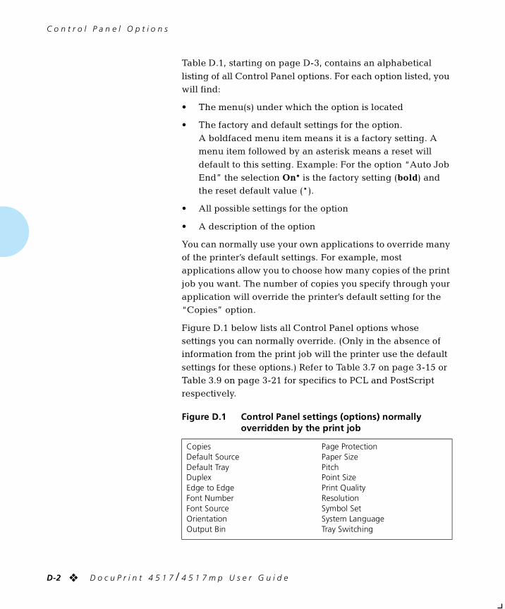
C o n t r o l P a n e l O p t i o n s
D-2 ❖ D o c u P r i n t 4 5 1 7 / 4 5 1 7 m p U s e r G u i d e
Table D.1, starting on page D-3, contains an alphabetical
listing of all Control Panel options. For each option listed, you will find:
• The menu(s) under which the option is located
• The factory and default settings for the option.
A boldfaced menu item means it is a factory setting. A menu item followed by an asterisk means a reset will
default to this setting. Example: For the option “Auto Job End” the selection On* is the factory setting (bold) and the reset default value (*).
• All possible settings for the option
• A description of the option
You can normally use your own applications to override many of the printer’s default settings. For example, most applications allow you to choose how many copies of the print
job you want. The number of copies you specify through your application will override the printer’s default setting for the “Copies” option.
Figure D.1 below lists all Control Panel options whose settings you can normally override. (Only in the absence of information from the print job will the printer use the default
settings for these options.) Refer to Table 3.7 on page 3-15 or Table 3.9 on page 3-21 for specifics to PCL and PostScript respectively.
Figure D.1 Control Panel settings (options) normally overridden by the print job
CopiesDefault SourceDefault TrayDuplexEdge to EdgeFont NumberFont SourceOrientationOutput Bin
Page ProtectionPaper SizePitchPoint SizePrint QualityResolutionSymbol SetSystem LanguageTray Switching
chapterd.frm Page 2 Friday, July 11, 1997 10:19 PM
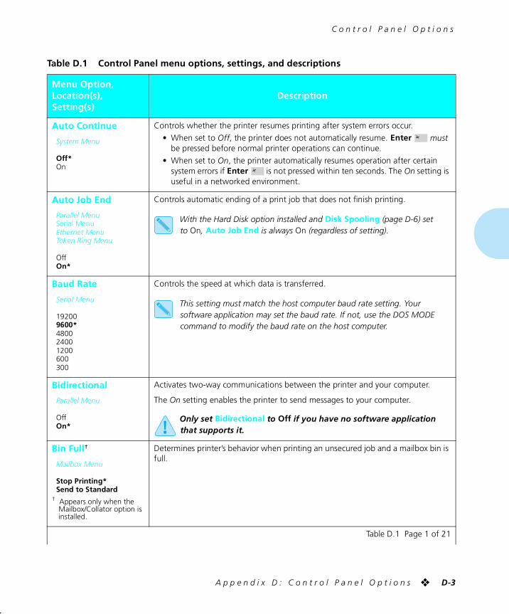
C o n t r o l P a n e l O p t i o n s
A p p e n d i x D : C o n t r o l P a n e l O p t i o n s ❖ D-3
Table D.1 Control Panel menu options, settings, and descriptions
Menu Option,Location(s),Setting(s)
Description
Auto Continue
System Menu
Off*On
Controls whether the printer resumes printing after system errors occur.
• When set to Off, the printer does not automatically resume. Enter must be pressed before normal printer operations can continue.
• When set to On, the printer automatically resumes operation after certain system errors if Enter is not pressed within ten seconds. The On setting is useful in a networked environment.
Auto Job End
Parallel MenuSerial MenuEthernet MenuToken Ring Menu
OffOn*
Controls automatic ending of a print job that does not finish printing.
With the Hard Disk option installed and Disk Spooling (page D-6) set to On, Auto Job End is always On (regardless of setting).
Baud Rate
Serial Menu
192009600*480024001200600300
Controls the speed at which data is transferred.
This setting must match the host computer baud rate setting. Your software application may set the baud rate. If not, use the DOS MODE command to modify the baud rate on the host computer.
Bidirectional
Parallel Menu
OffOn*
Activates two-way communications between the printer and your computer.
The On setting enables the printer to send messages to your computer.
Only set Bidirectional to Off if you have no software application that supports it.
Bin Full†
Mailbox Menu
Stop Printing*Send to Standard
† Appears only when the Mailbox/Collator option is installed.
Determines printer’s behavior when printing an unsecured job and a mailbox bin is full.
Table D.1 Page 1 of 21
chapterd.frm Page 3 Friday, July 11, 1997 10:19 PM
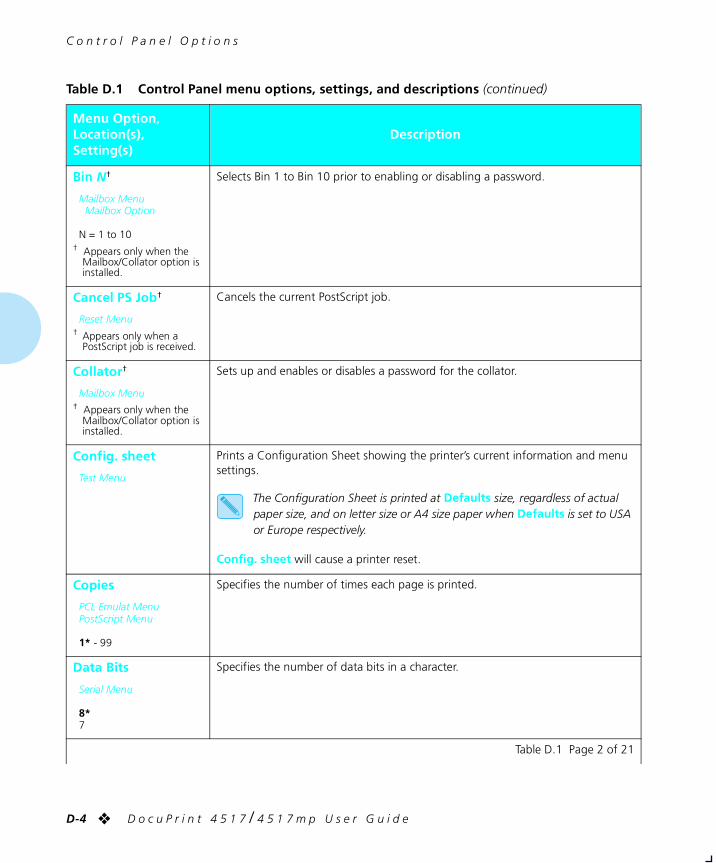
C o n t r o l P a n e l O p t i o n s
D-4 ❖ D o c u P r i n t 4 5 1 7 / 4 5 1 7 m p U s e r G u i d e
Bin N†
Mailbox MenuMailbox Option
N = 1 to 10† Appears only when the
Mailbox/Collator option is installed.
Selects Bin 1 to Bin 10 prior to enabling or disabling a password.
Cancel PS Job†
Reset Menu† Appears only when a
PostScript job is received.
Cancels the current PostScript job.
Collator†
Mailbox Menu† Appears only when the
Mailbox/Collator option is installed.
Sets up and enables or disables a password for the collator.
Config. sheet
Test Menu
Prints a Configuration Sheet showing the printer’s current information and menu settings.
The Configuration Sheet is printed at Defaults size, regardless of actual paper size, and on letter size or A4 size paper when Defaults is set to USA or Europe respectively.
Config. sheet will cause a printer reset.
Copies
PCL Emulat MenuPostScript Menu
1* - 99
Specifies the number of times each page is printed.
Data Bits
Serial Menu
8*7
Specifies the number of data bits in a character.
Table D.1 Control Panel menu options, settings, and descriptions (continued)
Menu Option,Location(s),Setting(s)
Description
Table D.1 Page 2 of 21
chapterd.frm Page 4 Friday, July 11, 1997 10:19 PM
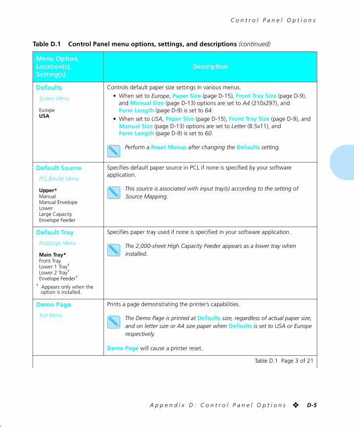
C o n t r o l P a n e l O p t i o n s
A p p e n d i x D : C o n t r o l P a n e l O p t i o n s ❖ D-5
Defaults
System Menu
EuropeUSA
Controls default paper size settings in various menus.
• When set to Europe, Paper Size (page D-15), Front Tray Size (page D-9), and Manual Size (page D-13) options are set to A4 (210x297), and Form Length (page D-9) is set to 64.
• When set to USA, Paper Size (page D-15), Front Tray Size (page D-9), and Manual Size (page D-13) options are set to Letter (8.5x11), and Form Length (page D-9) is set to 60.
Perform a Reset Menus after changing the Defaults setting.
Default Source
PCL Emulat Menu
Upper*ManualManual EnvelopeLowerLarge CapacityEnvelope Feeder
Specifies default paper source in PCL if none is specified by your software application.
This source is associated with input tray(s) according to the setting of Source Mapping.
Default Tray
PostScript Menu
Main Tray*Front TrayLower 1 Tray†
Lower 2 Tray†
Envelope Feeder†
† Appears only when the option is installed.
Specifies paper tray used if none is specified in your software application.
The 2,000-sheet High Capacity Feeder appears as a lower tray when installed.
Demo Page
Test Menu
Prints a page demonstrating the printer’s capabilities.
The Demo Page is printed at Defaults size, regardless of actual paper size, and on letter size or A4 size paper when Defaults is set to USA or Europe respectively.
Demo Page will cause a printer reset.
Table D.1 Control Panel menu options, settings, and descriptions (continued)
Menu Option,Location(s),Setting(s)
Description
Table D.1 Page 3 of 21
chapterd.frm Page 5 Friday, July 11, 1997 10:19 PM
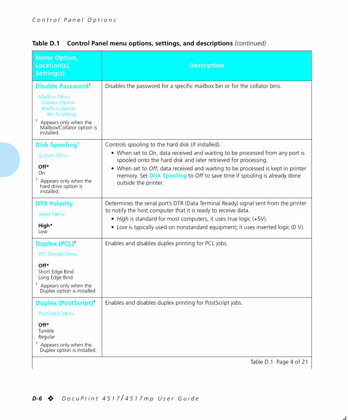
C o n t r o l P a n e l O p t i o n s
D-6 ❖ D o c u P r i n t 4 5 1 7 / 4 5 1 7 m p U s e r G u i d e
Disable Password†
Mailbox MenuCollator OptionMailbox Option
Bin N Setting† Appears only when the
Mailbox/Collator option is installed.
Disables the password for a specific mailbox bin or for the collator bins.
Disk Spooling†
System Menu
Off*On
† Appears only when the hard drive option is installed.
Controls spooling to the hard disk (if installed).
• When set to On, data received and waiting to be processed from any port is spooled onto the hard disk and later retrieved for processing.
• When set to Off, data received and waiting to be processed is kept in printer memory. Set Disk Spooling to Off to save time if spooling is already done outside the printer.
DTR Polarity
Serial Menu
High*Low
Determines the serial port’s DTR (Data Terminal Ready) signal sent from the printer to notify the host computer that it is ready to receive data.
• High is standard for most computers; it uses true logic (+5V).
• Low is typically used on nonstandard equipment; it uses inverted logic (0 V).
Duplex (PCL)†
PCL Emulat Menu
Off*Short Edge BindLong Edge Bind
† Appears only when the Duplex option is installed.
Enables and disables duplex printing for PCL jobs.
Duplex (PostScript)†
PostScript Menu
Off*TumbleRegular
† Appears only when the Duplex option is installed.
Enables and disables duplex printing for PostScript jobs.
Table D.1 Control Panel menu options, settings, and descriptions (continued)
Menu Option,Location(s),Setting(s)
Description
Table D.1 Page 4 of 21
chapterd.frm Page 6 Friday, July 11, 1997 10:19 PM
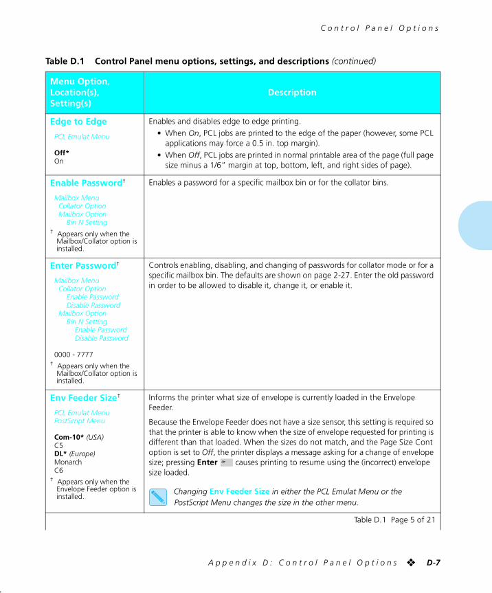
C o n t r o l P a n e l O p t i o n s
A p p e n d i x D : C o n t r o l P a n e l O p t i o n s ❖ D-7
Edge to Edge
PCL Emulat Menu
Off*On
Enables and disables edge to edge printing.
• When On, PCL jobs are printed to the edge of the paper (however, some PCL applications may force a 0.5 in. top margin).
• When Off, PCL jobs are printed in normal printable area of the page (full page size minus a 1/6” margin at top, bottom, left, and right sides of page).
Enable Password†
Mailbox MenuCollator OptionMailbox Option
Bin N Setting† Appears only when the
Mailbox/Collator option is installed.
Enables a password for a specific mailbox bin or for the collator bins.
Enter Password†
Mailbox MenuCollator Option
Enable PasswordDisable Password
Mailbox OptionBin N Setting
Enable PasswordDisable Password
0000 - 7777† Appears only when the
Mailbox/Collator option is installed.
Controls enabling, disabling, and changing of passwords for collator mode or for a specific mailbox bin. The defaults are shown on page 2-27. Enter the old password in order to be allowed to disable it, change it, or enable it.
Env Feeder Size†
PCL Emulat MenuPostScript Menu
Com-10* (USA)C5DL* (Europe)MonarchC6
† Appears only when the Envelope Feeder option is installed.
Informs the printer what size of envelope is currently loaded in the Envelope Feeder.
Because the Envelope Feeder does not have a size sensor, this setting is required so that the printer is able to know when the size of envelope requested for printing is different than that loaded. When the sizes do not match, and the Page Size Cont option is set to Off, the printer displays a message asking for a change of envelope size; pressing Enter causes printing to resume using the (incorrect) envelope size loaded.
Changing Env Feeder Size in either the PCL Emulat Menu or the PostScript Menu changes the size in the other menu.
Table D.1 Control Panel menu options, settings, and descriptions (continued)
Menu Option,Location(s),Setting(s)
Description
Table D.1 Page 5 of 21
chapterd.frm Page 7 Friday, July 11, 1997 10:19 PM
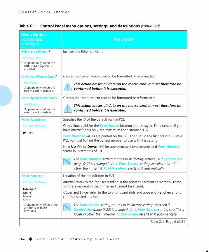
C o n t r o l P a n e l O p t i o n s
D-8 ❖ D o c u P r i n t 4 5 1 7 / 4 5 1 7 m p U s e r G u i d e
Ethernet Menu†
Interface Menu† Appears only when the
XNIC-E’NET option is installed.
Invokes the Ethernet Menu.
Fmt LwrMacroCard†
Test Menu† Appears only when the
macro card is installed.
Causes the Lower Macro card to be formatted or reformatted.
This action erases all data on the macro card. It must therefore be confirmed before it is executed.
Fmt UprMacroCard†
Test Menu† Appears only when the
macro card is installed.
Causes the Upper Macro card to be formatted or reformatted.
This action erases all data on the macro card. It must therefore be confirmed before it is executed.
Font Number
PCL Emulat Menu
0* - 999
Specifies the ID of the default font in PCL.
Only values valid for the Font Source location are displayed. For example, if you have internal fonts only, the maximum Font Number is 52.
Font Number values are printed on the PCL Font List in the first column. Print a PCL Font List to find the correct number to use with this setting.
Hold Up or Down for approximately two seconds and Font Number scrolls in increments of 10.
The Font Number setting returns to its factory setting (0) if Symbol Set (page D-22) is changed. If the Font Source setting specifies a location other than Internal, Font Number reverts to 0 automatically.
Font Source
PCL Emulat Menu
Internal*Upper†
Lower†
Soft†† Appears only when there
are fonts in these locations.
Location of the default font in PCL.
Internal refers to the font set residing in the printer’s permanent memory. These fonts are resident in the printer and cannot be altered.
Upper and Lower refer to the two font card slots and appear only when a font card is installed in a slot.
The Font Source setting returns to its factory setting (Internal) if Symbol Set (page D-22) is changed. If the Font Source setting specifies a location other than Internal, Font Number reverts to 0 automatically.
Table D.1 Control Panel menu options, settings, and descriptions (continued)
Menu Option,Location(s),Setting(s)
Description
Table D.1 Page 6 of 21
chapterd.frm Page 8 Friday, July 11, 1997 10:19 PM
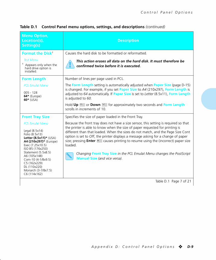
C o n t r o l P a n e l O p t i o n s
A p p e n d i x D : C o n t r o l P a n e l O p t i o n s ❖ D-9
Format the Disk†
Test Menu† Appears only when the
hard drive option is installed.
Causes the hard disk to be formatted or reformatted.
This action erases all data on the hard disk. It must therefore be confirmed twice before it is executed.
Form Length
PCL Emulat Menu
005 - 12864* (Europe)60* (USA)
Number of lines per page used in PCL.
The Form Length setting is automatically adjusted when Paper Size (page D-15) is changed. For example, if you set Paper Size to A4 (210x297), Form Length is adjusted to 64 automatically. If Paper Size is set to Letter (8.5x11), Form Length is adjusted to 60.
Hold Up or Down for approximately two seconds and Form Length scrolls in increments of 10.
Front Tray Size
PCL Emulat Menu
Legal (8.5x14)Folio (8.5x13)Letter (8.5x11)* (USA)A4 (210x297)* (Europe)Exec (7.25x10.5)ISO B5 (176x250)Statement (5.5x8.5)A6 (105x148)Com-10 (4-1/8x9.5)C5 (162x229)DL (110x220)Monarch (3-7/8x7.5)C6 (114x162)
Specifies the size of paper loaded in the Front Tray.
Because the front tray does not have a size sensor, this setting is required so that the printer is able to know when the size of paper requested for printing is different than that loaded. When the sizes do not match, and the Page Size Cont option is set to Off, the printer displays a message asking for a change of paper size; pressing Enter causes printing to resume using the (incorrect) paper size loaded.
Changing Front Tray Size in the PCL Emulat Menu changes the PostScript Manual Size (and vice versa).
Table D.1 Control Panel menu options, settings, and descriptions (continued)
Menu Option,Location(s),Setting(s)
Description
Table D.1 Page 7 of 21
chapterd.frm Page 9 Friday, July 11, 1997 10:19 PM
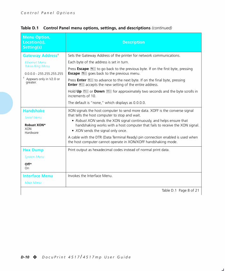
C o n t r o l P a n e l O p t i o n s
D-10 ❖ D o c u P r i n t 4 5 1 7 / 4 5 1 7 m p U s e r G u i d e
Gateway Address†
Ethernet MenuToken Ring Menu
0.0.0.0 - 255.255.255.255† Appears only in V2.0 or
greater.
Sets the Gateway Address of the printer for network communications.
Each byte of the address is set in turn.
Press Escape to go back to the previous byte. If on the first byte, pressing Escape goes back to the previous menu.
Press Enter to advance to the next byte. If on the final byte, pressing Enter accepts the new setting of the entire address.
Hold Up or Down for approximately two seconds and the byte scrolls in increments of 10.
The default is “none,” which displays as 0.0.0.0.
Handshake
Serial Menu
Robust XON*XONHardware
XON signals the host computer to send more data. XOFF is the converse signal that tells the host computer to stop and wait.
• Robust XON sends the XON signal continuously, and helps ensure that handshaking works with a host computer that fails to receive the XON signal.
• XON sends the signal only once.
A cable with the DTR (Data Terminal Ready) pin connection enabled is used when the host computer cannot operate in XON/XOFF handshaking mode.
Hex Dump
System Menu
Off*On
Print output as hexadecimal codes instead of normal print data.
Interface Menu
Main Menu
Invokes the Interface Menu.
Table D.1 Control Panel menu options, settings, and descriptions (continued)
Menu Option,Location(s),Setting(s)
Description
Table D.1 Page 8 of 21
chapterd.frm Page 10 Friday, July 11, 1997 10:19 PM
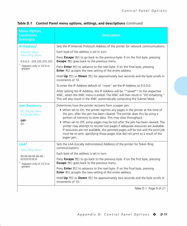
C o n t r o l P a n e l O p t i o n s
A p p e n d i x D : C o n t r o l P a n e l O p t i o n s ❖ D-11
IP Address†
Ethernet MenuToken Ring Menu
0.0.0.0 - 255.255.255.255† Appears only in V2.0 or
greater.
Sets the IP (Internet Protocol) Address of the printer for network communications.
Each byte of the address is set in turn.
Press Escape to go back to the previous byte. If on the first byte, pressing Escape goes back to the previous menu.
Press Enter to advance to the next byte. If on the final byte, pressing Enter accepts the new setting of the entire address.
Hold Up or Down for approximately two seconds and the byte scrolls in increments of 10.
To enter the IP Address default of “none” set the IP Address to 0.0.0.0.
After setting the IP Address, the IP Address will be “*saved*” to the respective XNIC, when the XNIC menu is exited. The XNIC will then result in “I/O Initializing.” This will also result in the XNIC automatically computing the Subnet Mask.
Jam Recovery
PCL Emulat MenuPostScript Menu
Off*On
Determines how the printer recovers from a paper jam.
• When set to On, the printer reprints any pages in the printer at the time of the jam, after the jam has been cleared. The printer does this by using a portion of memory to store data. This may slow throughput.
• When set to Off, some pages may be lost after the jam has been cleared. The printer may attempt to recover lost pages if adequate resources are available. If resources are not available, the jammed pages will be lost and the print job must be re-sent, specifying those pages that did not print as a result of the paper jam.
LAA†
Token Ring Menu
00.00.00.00.00.00 - FF.FF.FF.FF.FF.FF
† Appears only in V2.0 or greater.
Sets the LAA (Locally Administered Address) of the printer for Token Ring communications.
Each byte of the address is set in turn.
Press Escape to go back to the previous byte. If on the first byte, pressing Escape goes back to the previous menu.
Press Enter to advance to the next byte. If on the final byte, pressing Enter accepts the new setting of the entire address.
Hold Up or Down for approximately two seconds and the byte scrolls in increments of 10.
Table D.1 Control Panel menu options, settings, and descriptions (continued)
Menu Option,Location(s),Setting(s)
Description
Table D.1 Page 9 of 21
chapterd.frm Page 11 Friday, July 11, 1997 10:19 PM
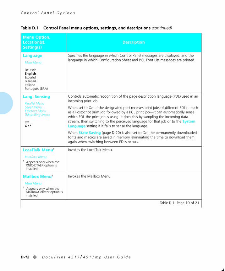
C o n t r o l P a n e l O p t i o n s
D-12 ❖ D o c u P r i n t 4 5 1 7 / 4 5 1 7 m p U s e r G u i d e
Language
Main Menu
DeutschEnglishEspañolFrançaisItalianoPortuguês (BRA)
Specifies the language in which Control Panel messages are displayed, and the language in which Configuration Sheet and PCL Font List messages are printed.
Lang. Sensing
Parallel MenuSerial MenuEthernet MenuToken Ring Menu
OffOn*
Controls automatic recognition of the page description language (PDL) used in an incoming print job.
When set to On, if the designated port receives print jobs of different PDLs—such as a PostScript print job followed by a PCL print job—it can automatically sense which PDL the print job is using. It does this by sampling the incoming data stream, then switching to the perceived language for that job or to the System Language setting if it fails to sense the language.
When State Saving (page D-20) is also set to On, the permanently downloaded fonts and macros are saved in memory, eliminating the time to download them again when switching between PDLs occurs.
LocalTalk Menu†
Interface Menu† Appears only when the
XNIC-L’TALK option is installed.
Invokes the LocalTalk Menu.
Mailbox Menu†
Main Menu† Appears only when the
Mailbox/Collator option is installed.
Invokes the Mailbox Menu.
Table D.1 Control Panel menu options, settings, and descriptions (continued)
Menu Option,Location(s),Setting(s)
Description
Table D.1 Page 10 of 21
chapterd.frm Page 12 Friday, July 11, 1997 10:19 PM
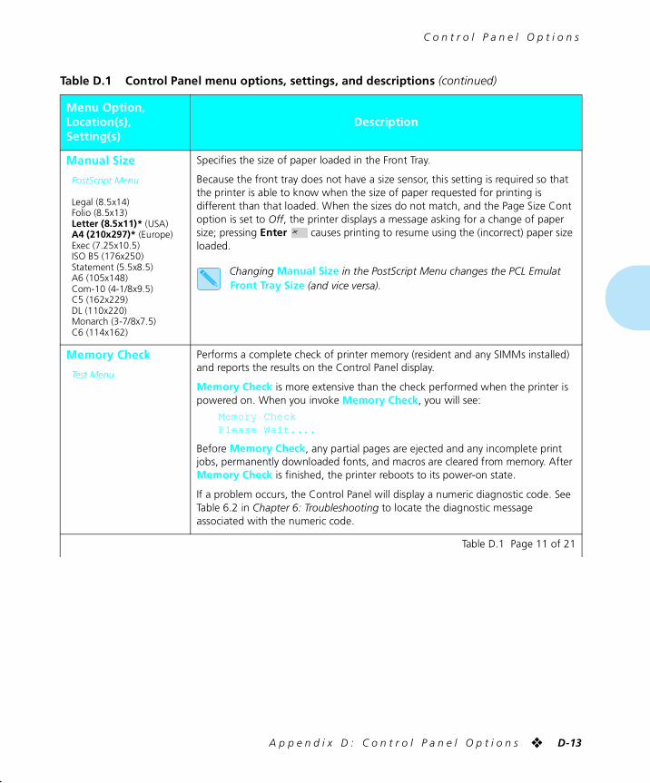
C o n t r o l P a n e l O p t i o n s
A p p e n d i x D : C o n t r o l P a n e l O p t i o n s ❖ D-13
Manual Size
PostScript Menu
Legal (8.5x14)Folio (8.5x13)Letter (8.5x11)* (USA)A4 (210x297)* (Europe)Exec (7.25x10.5)ISO B5 (176x250)Statement (5.5x8.5)A6 (105x148)Com-10 (4-1/8x9.5)C5 (162x229)DL (110x220)Monarch (3-7/8x7.5)C6 (114x162)
Specifies the size of paper loaded in the Front Tray.
Because the front tray does not have a size sensor, this setting is required so that the printer is able to know when the size of paper requested for printing is different than that loaded. When the sizes do not match, and the Page Size Cont option is set to Off, the printer displays a message asking for a change of paper size; pressing Enter causes printing to resume using the (incorrect) paper size loaded.
Changing Manual Size in the PostScript Menu changes the PCL Emulat Front Tray Size (and vice versa).
Memory Check
Test Menu
Performs a complete check of printer memory (resident and any SIMMs installed) and reports the results on the Control Panel display.
Memory Check is more extensive than the check performed when the printer is powered on. When you invoke Memory Check, you will see:
Memory CheckPlease Wait....
Before Memory Check, any partial pages are ejected and any incomplete print jobs, permanently downloaded fonts, and macros are cleared from memory. After Memory Check is finished, the printer reboots to its power-on state.
If a problem occurs, the Control Panel will display a numeric diagnostic code. See Table 6.2 in Chapter 6: Troubleshooting to locate the diagnostic message associated with the numeric code.
Table D.1 Control Panel menu options, settings, and descriptions (continued)
Menu Option,Location(s),Setting(s)
Description
Table D.1 Page 11 of 21
chapterd.frm Page 13 Friday, July 11, 1997 10:19 PM
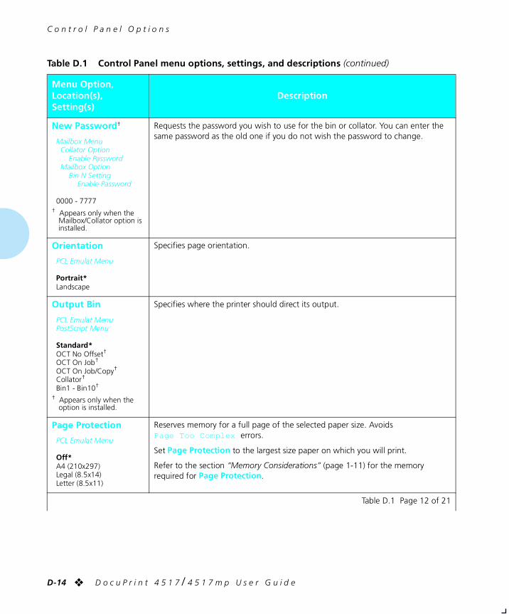
C o n t r o l P a n e l O p t i o n s
D-14 ❖ D o c u P r i n t 4 5 1 7 / 4 5 1 7 m p U s e r G u i d e
New Password†
Mailbox MenuCollator Option
Enable PasswordMailbox Option
Bin N SettingEnable Password
0000 - 7777† Appears only when the
Mailbox/Collator option is installed.
Requests the password you wish to use for the bin or collator. You can enter the same password as the old one if you do not wish the password to change.
Orientation
PCL Emulat Menu
Portrait*Landscape
Specifies page orientation.
Output Bin
PCL Emulat MenuPostScript Menu
Standard*OCT No Offset†
OCT On Job†
OCT On Job/Copy†
Collator†
Bin1 - Bin10†
† Appears only when the option is installed.
Specifies where the printer should direct its output.
Page Protection
PCL Emulat Menu
Off*A4 (210x297)Legal (8.5x14)Letter (8.5x11)
Reserves memory for a full page of the selected paper size. Avoids Page Too Complex errors.
Set Page Protection to the largest size paper on which you will print.
Refer to the section “Memory Considerations” (page 1-11) for the memory required for Page Protection.
Table D.1 Control Panel menu options, settings, and descriptions (continued)
Menu Option,Location(s),Setting(s)
Description
Table D.1 Page 12 of 21
chapterd.frm Page 14 Friday, July 11, 1997 10:19 PM
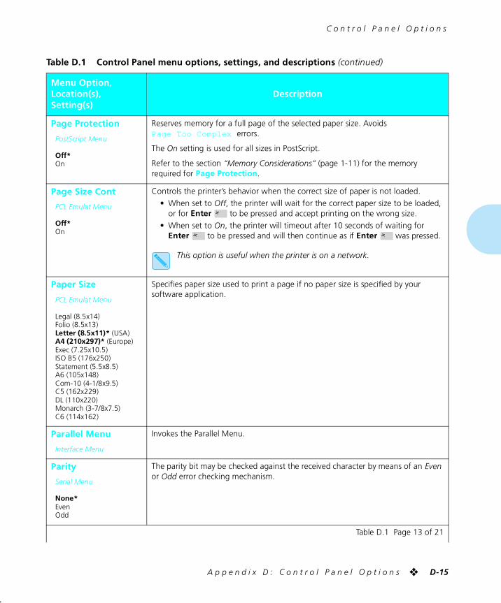
C o n t r o l P a n e l O p t i o n s
A p p e n d i x D : C o n t r o l P a n e l O p t i o n s ❖ D-15
Page Protection
PostScript Menu
Off*On
Reserves memory for a full page of the selected paper size. Avoids Page Too Complex errors.
The On setting is used for all sizes in PostScript.
Refer to the section “Memory Considerations” (page 1-11) for the memory required for Page Protection.
Page Size Cont
PCL Emulat Menu
Off*On
Controls the printer’s behavior when the correct size of paper is not loaded.
• When set to Off, the printer will wait for the correct paper size to be loaded, or for Enter to be pressed and accept printing on the wrong size.
• When set to On, the printer will timeout after 10 seconds of waiting for Enter to be pressed and will then continue as if Enter was pressed.
This option is useful when the printer is on a network.
Paper Size
PCL Emulat Menu
Legal (8.5x14)Folio (8.5x13)Letter (8.5x11)* (USA)A4 (210x297)* (Europe)Exec (7.25x10.5)ISO B5 (176x250)Statement (5.5x8.5)A6 (105x148)Com-10 (4-1/8x9.5)C5 (162x229)DL (110x220)Monarch (3-7/8x7.5)C6 (114x162)
Specifies paper size used to print a page if no paper size is specified by your software application.
Parallel Menu
Interface Menu
Invokes the Parallel Menu.
Parity
Serial Menu
None*EvenOdd
The parity bit may be checked against the received character by means of an Even or Odd error checking mechanism.
Table D.1 Control Panel menu options, settings, and descriptions (continued)
Menu Option,Location(s),Setting(s)
Description
Table D.1 Page 13 of 21
chapterd.frm Page 15 Friday, July 11, 1997 10:19 PM
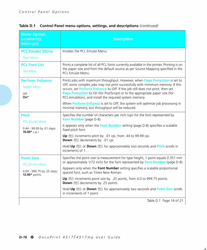
C o n t r o l P a n e l O p t i o n s
D-16 ❖ D o c u P r i n t 4 5 1 7 / 4 5 1 7 m p U s e r G u i d e
PCL Emulat Menu
Main Menu
Invokes the PCL Emulat Menu.
PCL Font List
Test Menu
Prints a complete list of all PCL fonts currently available in the printer. Printing is on the paper size and from the default source as per Source Mapping specified in the PCL Emulat Menu.
Perform Enhance
System Menu
OffOn*
Prints jobs with maximum throughput. However, when Page Protection is set to Off, some complex jobs may not print successfully with minimum memory. If this occurs, set Perform Enhance to Off. If the job still does not print, then set Page Protection to On (for PostScript) or to the appropriate paper size (for PCL emulation), and install the required system memory.
When Perform Enhance is set to Off, the system will optimize job processing in minimal memory, but throughput will be reduced.
Pitch
PCL Emulat Menu
0.44 - 99.99 by .01 steps10.00* c.p.i.
Specifies the number of characters per inch (cpi) for the font represented by Font Number (page D-8).
It appears only when the Font Number setting (page D-8) specifies a scalable fixed pitch font.
Up increments pitch by .01 cpi, from .44 to 99.99 cpi. Down decrements by .01 cpi.
Hold Up or Down for approximately two seconds and Pitch scrolls in increments of 1.
Point Size
PCL Emulat Menu
4.00 - 999.75 by .25 steps12.00* points
Specifies the point size (a measurement for type height, 1 point equals 0.351 mm or approximately 1/72 inch) for the font represented by Font Number (page D-8).
Appears only when the Font Number setting specifies a scalable proportional spaced font, such as Times New Roman.
Up increments point size by .25 points, from 4.0 to 999.75 points. Down decrements by .25 points.
Hold Up or Down for approximately two seconds and Point Size scrolls in increments of 1 point.
Table D.1 Control Panel menu options, settings, and descriptions (continued)
Menu Option,Location(s),Setting(s)
Description
Table D.1 Page 14 of 21
chapterd.frm Page 16 Friday, July 11, 1997 10:19 PM
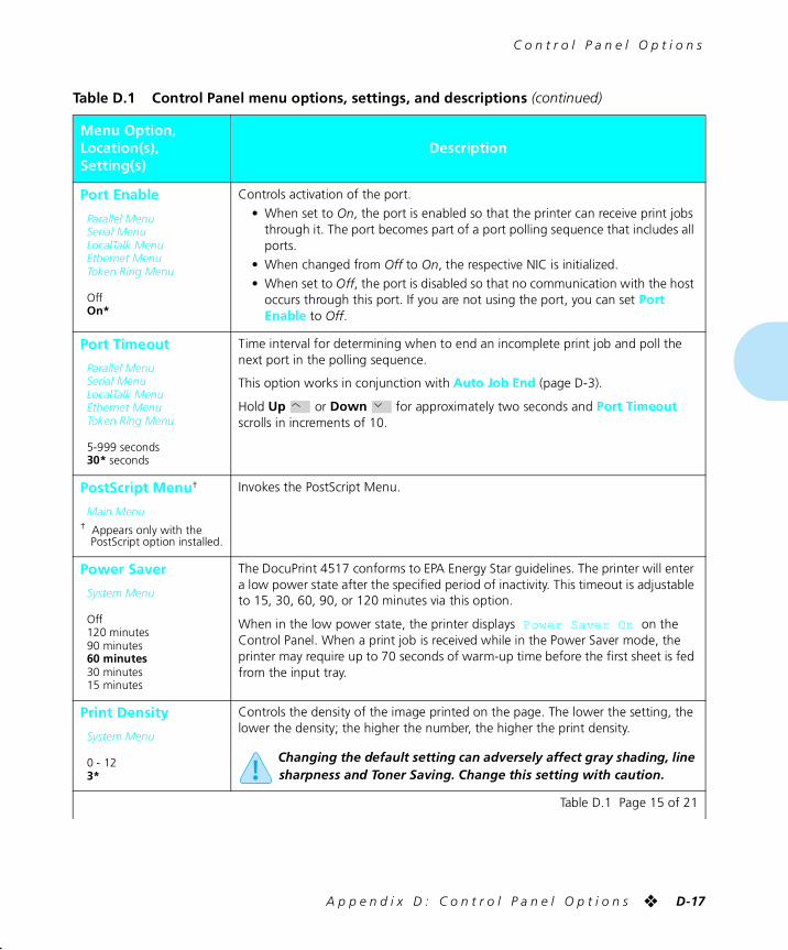
C o n t r o l P a n e l O p t i o n s
A p p e n d i x D : C o n t r o l P a n e l O p t i o n s ❖ D-17
Port Enable
Parallel MenuSerial MenuLocalTalk MenuEthernet MenuToken Ring Menu
OffOn*
Controls activation of the port.
• When set to On, the port is enabled so that the printer can receive print jobs through it. The port becomes part of a port polling sequence that includes all ports.
• When changed from Off to On, the respective NIC is initialized.
• When set to Off, the port is disabled so that no communication with the host occurs through this port. If you are not using the port, you can set Port Enable to Off.
Port Timeout
Parallel MenuSerial MenuLocalTalk MenuEthernet MenuToken Ring Menu
5-999 seconds30* seconds
Time interval for determining when to end an incomplete print job and poll the next port in the polling sequence.
This option works in conjunction with Auto Job End (page D-3).
Hold Up or Down for approximately two seconds and Port Timeout scrolls in increments of 10.
PostScript Menu†
Main Menu† Appears only with the
PostScript option installed.
Invokes the PostScript Menu.
Power Saver
System Menu
Off120 minutes90 minutes60 minutes30 minutes15 minutes
The DocuPrint 4517 conforms to EPA Energy Star guidelines. The printer will enter a low power state after the specified period of inactivity. This timeout is adjustable to 15, 30, 60, 90, or 120 minutes via this option.
When in the low power state, the printer displays Power Saver On on the Control Panel. When a print job is received while in the Power Saver mode, the printer may require up to 70 seconds of warm-up time before the first sheet is fed from the input tray.
Print Density
System Menu
0 - 123*
Controls the density of the image printed on the page. The lower the setting, the lower the density; the higher the number, the higher the print density.
Changing the default setting can adversely affect gray shading, line sharpness and Toner Saving. Change this setting with caution.
Table D.1 Control Panel menu options, settings, and descriptions (continued)
Menu Option,Location(s),Setting(s)
Description
Table D.1 Page 15 of 21
chapterd.frm Page 17 Friday, July 11, 1997 10:19 PM
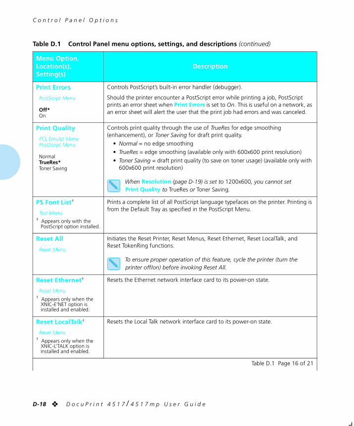
C o n t r o l P a n e l O p t i o n s
D-18 ❖ D o c u P r i n t 4 5 1 7 / 4 5 1 7 m p U s e r G u i d e
Print Errors
PostScript Menu
Off*On
Controls PostScript’s built-in error handler (debugger).
Should the printer encounter a PostScript error while printing a job, PostScript prints an error sheet when Print Errors is set to On. This is useful on a network, as an error sheet will alert the user that the print job had errors and was canceled.
Print Quality
PCL Emulat MenuPostScript Menu
NormalTrueRes*Toner Saving
Controls print quality through the use of TrueRes for edge smoothing (enhancement), or Toner Saving for draft print quality.
• Normal = no edge smoothing
• TrueRes = edge smoothing (available only with 600x600 print resolution)
• Toner Saving = draft print quality (to save on toner usage) (available only with 600x600 print resolution)
When Resolution (page D-19) is set to 1200x600, you cannot set Print Quality to TrueRes or Toner Saving.
PS Font List†
Test Menu† Appears only with the
PostScript option installed.
Prints a complete list of all PostScript language typefaces on the printer. Printing is from the Default Tray as specified in the PostScript Menu.
Reset All
Reset Menu
Initiates the Reset Printer, Reset Menus, Reset Ethernet, Reset LocalTalk, and Reset TokenRing functions.
To ensure proper operation of this feature, cycle the printer (turn the printer off/on) before invoking Reset All.
Reset Ethernet†
Reset Menu† Appears only when the
XNIC-E’NET option is installed and enabled.
Resets the Ethernet network interface card to its power-on state.
Reset LocalTalk†
Reset Menu† Appears only when the
XNIC-L’TALK option is installed and enabled.
Resets the Local Talk network interface card to its power-on state.
Table D.1 Control Panel menu options, settings, and descriptions (continued)
Menu Option,Location(s),Setting(s)
Description
Table D.1 Page 16 of 21
chapterd.frm Page 18 Friday, July 11, 1997 10:19 PM
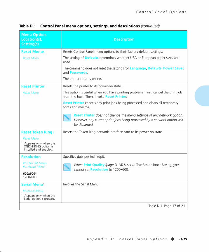
C o n t r o l P a n e l O p t i o n s
A p p e n d i x D : C o n t r o l P a n e l O p t i o n s ❖ D-19
Reset Menus
Reset Menu
Resets Control Panel menu options to their factory default settings.
The setting of Defaults determines whether USA or European paper sizes are used.
The command does not reset the settings for Language, Defaults, Power Saver, and Passwords.
The printer returns online.
Reset Printer
Reset Menu
Resets the printer to its power-on state.
This option is useful when you have printing problems. First, cancel the print job from the host. Then, invoke Reset Printer.
Reset Printer cancels any print jobs being processed and clears all temporary fonts and macros.
Reset Printer does not change the menu settings of any network option. However, any current print jobs being processed by a network option will be discarded.
Reset Token Ring†
Reset Menu† Appears only when the
XNIC-T’RING option is installed and enabled.
Resets the Token Ring network interface card to its power-on state.
Resolution
PCL Emulat MenuPostScript Menu
600x600*1200x600
Specifies dots per inch (dpi).
When Print Quality (page D-18) is set to TrueRes or Toner Saving, you cannot set Resolution to 1200x600.
Serial Menu†
Interface Menu† Appears only when the
Serial option is present.
Invokes the Serial Menu.
Table D.1 Control Panel menu options, settings, and descriptions (continued)
Menu Option,Location(s),Setting(s)
Description
Table D.1 Page 17 of 21
chapterd.frm Page 19 Friday, July 11, 1997 10:19 PM
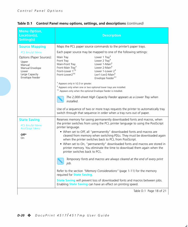
C o n t r o l P a n e l O p t i o n s
D-20 ❖ D o c u P r i n t 4 5 1 7 / 4 5 1 7 m p U s e r G u i d e
Source Mapping
PCL Emulat Menu
Options (Paper Sources):UpperManualManual EnvelopeLowerLarge CapacityEnvelope Feeder
Maps the PCL paper source commands to the printer’s paper trays.
Each paper source may be mapped to one of the following settings:
Main Tray Lower 1 Tray‡
Front Tray Lower 2 Tray‡
Main-Front Tray Lower 1-Main‡
Front-Main Tray† Lower 2-Main‡
Front-Lower 1†‡ Lower 1-Lower 2‡
Front-Lower2†‡ Lwr1-Lwr2-Main‡
Envelope Feeder††
† Appears only in V2.0 or greater.‡ Appears only when one or two optional lower trays are installed.†† Appears only when the optional Envelope Feeder is installed.
The 2,000-sheet High Capacity Feeder appears as a Lower Tray when installed.
Use of a sequence of two or more trays requests the printer to automatically tray switch through that sequence in order when a tray runs out of paper.
State Saving
PCL Emulat MenuPostScript Menu
Off*On
Reserves memory for saving permanently downloaded fonts and macros, when the printer switches from using the PCL printer language to using the PostScript printer language.
• When set to Off, all “permanently” downloaded fonts and macros are cleared from memory when switching PDLs. They must be downloaded again when the printer switches back to PCL from PostScript.
• When set to On, “permanently” downloaded fonts and macros are stored in printer memory. You eliminate the time to download them again when the printer switches back to PCL.
Temporary fonts and macros are always cleared at the end of every print job.
Refer to the section “Memory Considerations” (page 1-11) for the memory required for State Saving.
State Saving will prevent loss of downloaded fonts and macros between jobs. Enabling State Saving can have an effect on printing speed.
Table D.1 Control Panel menu options, settings, and descriptions (continued)
Menu Option,Location(s),Setting(s)
Description
Table D.1 Page 18 of 21
chapterd.frm Page 20 Friday, July 11, 1997 10:19 PM
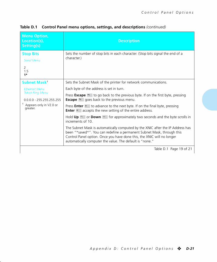
C o n t r o l P a n e l O p t i o n s
A p p e n d i x D : C o n t r o l P a n e l O p t i o n s ❖ D-21
Stop Bits
Serial Menu
21.51*
Sets the number of stop bits in each character. (Stop bits signal the end of a character.)
Subnet Mask†
Ethernet MenuToken Ring Menu
0.0.0.0 - 255.255.255.255† Appears only in V2.0 or
greater.
Sets the Subnet Mask of the printer for network communications.
Each byte of the address is set in turn.
Press Escape to go back to the previous byte. If on the first byte, pressing Escape goes back to the previous menu.
Press Enter to advance to the next byte. If on the final byte, pressing Enter accepts the new setting of the entire address.
Hold Up or Down for approximately two seconds and the byte scrolls in increments of 10.
The Subnet Mask is automatically computed by the XNIC after the IP Address has been “*saved*”. You can redefine a permanent Subnet Mask, through this Control Panel option. Once you have done this, the XNIC will no longer automatically computer the value. The default is “none.”
Table D.1 Control Panel menu options, settings, and descriptions (continued)
Menu Option,Location(s),Setting(s)
Description
Table D.1 Page 19 of 21
chapterd.frm Page 21 Friday, July 11, 1997 10:19 PM
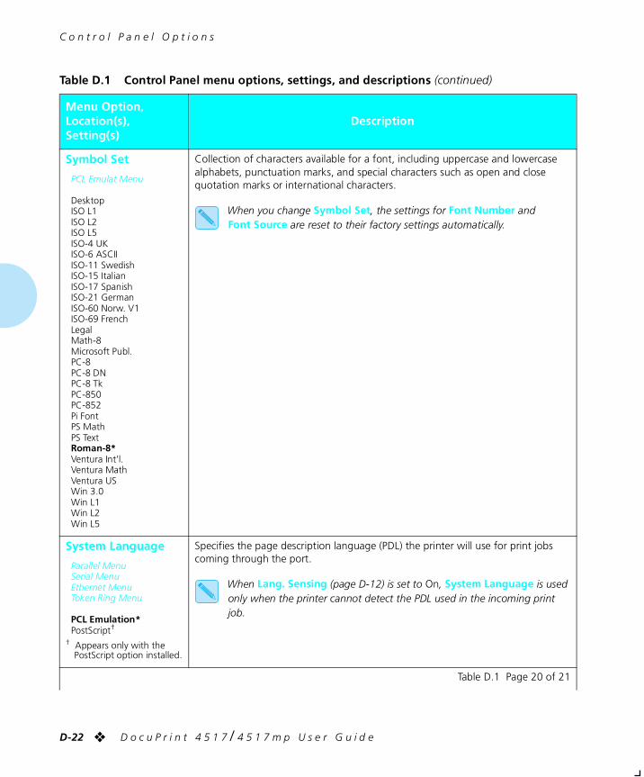
C o n t r o l P a n e l O p t i o n s
D-22 ❖ D o c u P r i n t 4 5 1 7 / 4 5 1 7 m p U s e r G u i d e
Symbol Set
PCL Emulat Menu
DesktopISO L1ISO L2ISO L5ISO-4 UKISO-6 ASCIIISO-11 SwedishISO-15 ItalianISO-17 SpanishISO-21 GermanISO-60 Norw. V1ISO-69 FrenchLegalMath-8Microsoft Publ.PC-8PC-8 DNPC-8 TkPC-850PC-852Pi FontPS MathPS TextRoman-8*Ventura Int’l.Ventura MathVentura USWin 3.0Win L1Win L2Win L5
Collection of characters available for a font, including uppercase and lowercase alphabets, punctuation marks, and special characters such as open and close quotation marks or international characters.
When you change Symbol Set, the settings for Font Number and Font Source are reset to their factory settings automatically.
System Language
Parallel MenuSerial MenuEthernet MenuToken Ring Menu
PCL Emulation*PostScript†
† Appears only with the PostScript option installed.
Specifies the page description language (PDL) the printer will use for print jobs coming through the port.
When Lang. Sensing (page D-12) is set to On, System Language is used only when the printer cannot detect the PDL used in the incoming print job.
Table D.1 Control Panel menu options, settings, and descriptions (continued)
Menu Option,Location(s),Setting(s)
Description
Table D.1 Page 20 of 21
chapterd.frm Page 22 Friday, July 11, 1997 10:19 PM
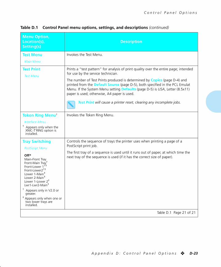
C o n t r o l P a n e l O p t i o n s
A p p e n d i x D : C o n t r o l P a n e l O p t i o n s ❖ D-23
Test Menu
Main Menu
Invokes the Test Menu.
Test Print
Test Menu
Prints a “test pattern” for analysis of print quality over the entire page; intended for use by the service technician.
The number of Test Prints produced is determined by Copies (page D-4) and printed from the Default Source (page D-5), both specified in the PCL Emulat Menu. If the System Menu setting Defaults (page D-5) is USA, Letter (8.5x11) paper is used; otherwise, A4 paper is used.
Test Print will cause a printer reset, clearing any incomplete jobs.
Token Ring Menu†
Interface Menu† Appears only when the
XNIC-T’RING option is installed.
Invokes the Token Ring Menu.
Tray Switching
PostScript Menu
Off*Main-Front TrayFront-Main Tray†
Front-Lower 1†‡
Front-Lower2†‡
Lower 1-Main‡
Lower 2-Main‡
Lower 1-Lower 2‡
Lwr1-Lwr2-Main‡
† Appears only in V2.0 or greater.
‡ Appears only when one or two lower trays are installed.
Controls the sequence of trays the printer uses when printing a page of a PostScript print job.
The first tray of a sequence is used until it runs out of paper, at which time the next tray of the sequence is used (if it has the correct size of paper).
Table D.1 Control Panel menu options, settings, and descriptions (continued)
Menu Option,Location(s),Setting(s)
Description
Table D.1 Page 21 of 21
chapterd.frm Page 23 Friday, July 11, 1997 10:19 PM

D-24 ❖ D o c u P r i n t 4 5 1 7 / 4 5 1 7 m p U s e r G u i d e
chapterd.frm Page 24 Friday, July 11, 1997 10:19 PM
Appendix E
A p p e n d i x E : P r i n t e r R e s i d e n t F o n t s ❖ E-1
Printer Resident Fonts AppendixE
Base Printer Fonts ................................................................. E-2
Printing a PCL Font List ......................................................... E-3
PostScript Fonts .................................................................... E-4
chaptere.frm Page 1 Friday, July 11, 1997 8:56 PM
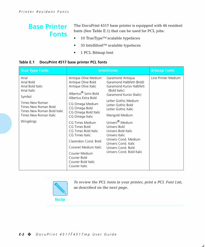
P r i n t e r R e s i d e n t F o n t s
E-2 ❖ D o c u P r i n t 4 5 1 7 / 4 5 1 7 m p U s e r G u i d e
Base PrinterFonts
The DocuPrint 4517 base printer is equipped with 46 resident
fonts (See Table E.1) that can be used for PCL jobs:
• 10 TrueType™ scalable typefaces
• 35 Intellifont™ scalable typefaces
• 1 PCL Bitmap font
Table E.1 DocuPrint 4517 base printer PCL fonts
True Type Fonts Intellifonts Bitmap Fonts
ArialArial BoldArial Bold ItalicArial Italic
Symbol
Times New RomanTimes New Roman BoldTimes New Roman Bold ItalicTimes New Roman Italic
Wingdings
Antique Olive MediumAntique Olive BoldAntique Olive Italic
Albertus® Semi BoldAlbertus Extra Bold
CG Omega MediumCG Omega BoldCG Omega Bold ItalicCG Omega Italic
CG Times MediumCG Times BoldCG Times Bold ItalicCG Times Italic
Clarendon Cond. Bold
Coronet Medium Italic
Courier MediumCourier BoldCourier Bold ItalicCourier Italic
Garamond AntiquaGaramond Halbfett (Bold)Garamond Kursiv Halbfett(Bold Italic)
Garamond Kursiv (Italic)
Letter Gothic MediumLetter Gothic BoldLetter Gothic Italic
Marigold Medium
Univers® MediumUnivers BoldUnivers Bold ItalicUnivers ItalicUnivers Cond. MediumUnivers Cond. ItalicUnivers Cond. BoldUnivers Cond. Bold Italic
Line Printer Medium
Note
To review the PCL fonts in your printer, print a PCL Font List,
as described on the next page.
chaptere.frm Page 2 Friday, July 11, 1997 8:56 PM
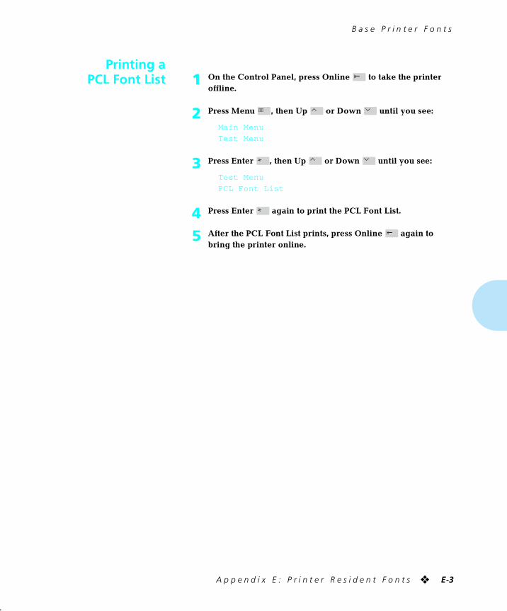
B a s e P r i n t e r F o n t s
A p p e n d i x E : P r i n t e r R e s i d e n t F o n t s ❖ E-3
Printing aPCL Font List 1 On the Control Panel, press Online to take the printer
offline.
2 Press Menu , then Up or Down until you see:
Main Menu
Test Menu
3 Press Enter , then Up or Down until you see:
Test Menu
PCL Font List
4 Press Enter again to print the PCL Font List.
5 After the PCL Font List prints, press Online again to bring the printer online.
chaptere.frm Page 3 Friday, July 11, 1997 8:56 PM
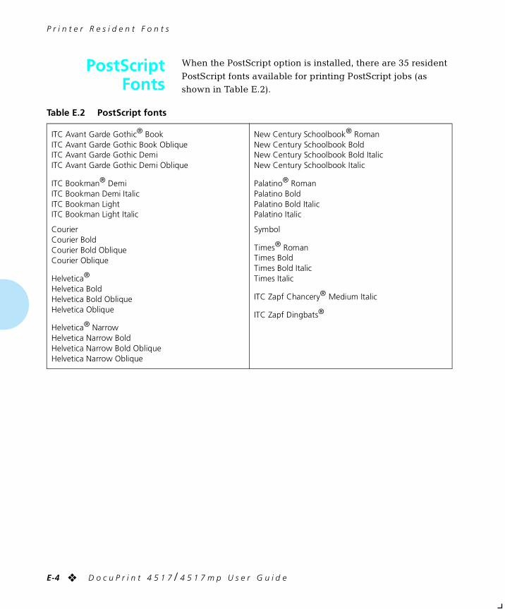
P r i n t e r R e s i d e n t F o n t s
E-4 ❖ D o c u P r i n t 4 5 1 7 / 4 5 1 7 m p U s e r G u i d e
PostScriptFonts
When the PostScript option is installed, there are 35 resident
PostScript fonts available for printing PostScript jobs (as shown in Table E.2).
Table E.2 PostScript fonts
ITC Avant Garde Gothic® BookITC Avant Garde Gothic Book ObliqueITC Avant Garde Gothic DemiITC Avant Garde Gothic Demi Oblique
ITC Bookman® DemiITC Bookman Demi ItalicITC Bookman LightITC Bookman Light Italic
CourierCourier BoldCourier Bold ObliqueCourier Oblique
Helvetica®
Helvetica BoldHelvetica Bold ObliqueHelvetica Oblique
Helvetica® NarrowHelvetica Narrow BoldHelvetica Narrow Bold ObliqueHelvetica Narrow Oblique
New Century Schoolbook® RomanNew Century Schoolbook BoldNew Century Schoolbook Bold ItalicNew Century Schoolbook Italic
Palatino® RomanPalatino BoldPalatino Bold ItalicPalatino Italic
Symbol
Times® RomanTimes BoldTimes Bold ItalicTimes Italic
ITC Zapf Chancery® Medium Italic
ITC Zapf Dingbats®
chaptere.frm Page 4 Friday, July 11, 1997 8:56 PM
Appendix F
A p p e n d i x F : P r i n t e r S p e c i f i c a t i o n s ❖ F-1
Printer Specifications AppendixF
chapterf.frm Page 1 Friday, July 11, 1997 9:04 PM
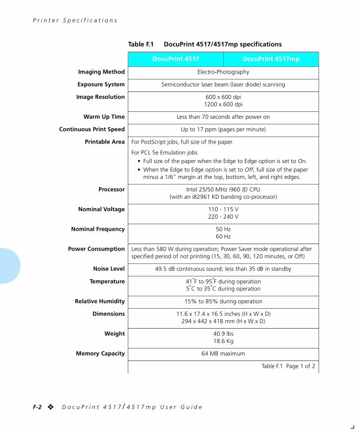
P r i n t e r S p e c i f i c a t i o n s
F-2 ❖ D o c u P r i n t 4 5 1 7 / 4 5 1 7 m p U s e r G u i d e
Table F.1 DocuPrint 4517/4517mp specifications
DocuPrint 4517 DocuPrint 4517mp
Imaging Method Electro-Photography
Exposure System Semiconductor laser beam (laser diode) scanning
Image Resolution 600 x 600 dpi1200 x 600 dpi
Warm Up Time Less than 70 seconds after power on
Continuous Print Speed Up to 17 ppm (pages per minute)
Printable Area For PostScript jobs, full size of the paper.
For PCL 5e Emulation jobs
• Full size of the paper when the Edge to Edge option is set to On.
• When the Edge to Edge option is set to Off, full size of the paper minus a 1/6” margin at the top, bottom, left, and right edges.
Processor Intel 25/50 MHz i960 JD CPU (with an i82961 KD banding co-processor)
Nominal Voltage 110 - 115 V220 - 240 V
Nominal Frequency 50 Hz60 Hz
Power Consumption Less than 580 W during operation; Power Saver mode operational after specified period of not printing (15, 30, 60, 90, 120 minutes, or Off)
Noise Level 49.5 dB continuous sound; less than 35 dB in standby
Temperature 41°F to 95°F during operation5°C to 35°C during operation
Relative Humidity 15% to 85% during operation
Dimensions 11.6 x 17.4 x 16.5 inches (H x W x D)294 x 442 x 418 mm (H x W x D)
Weight 40.9 lbs18.6 Kg
Memory Capacity 64 MB maximum
Table F.1 Page 1 of 2
chapterf.frm Page 2 Friday, July 11, 1997 9:04 PM
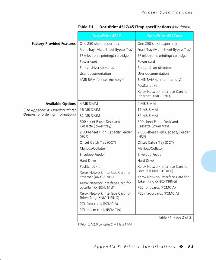
P r i n t e r S p e c i f i c a t i o n s
A p p e n d i x F : P r i n t e r S p e c i f i c a t i o n s ❖ F-3
† Prior to V2.0 contains 2 MB less RAM.
Factory-Provided Features One 250-sheet paper tray
Front Tray (Multi-Sheet Bypass Tray)
EP (electronic printing) cartridge
Power cord
Printer driver diskettes
User documentation
4MB RAM (printer memory)†
One 250-sheet paper tray
Front Tray (Multi-Sheet Bypass Tray)
EP (electronic printing) cartridge
Power cord
Printer driver diskettes
User documentation
8 MB RAM (printer memory)†
PostScript kit
Xerox Network Interface Card for Ethernet (XNIC-E’NET)
Available Options
(See Appendix A: Ordering PrinterOptions for ordering information.)
4 MB SIMM
16 MB SIMM
32 MB SIMM
500-sheet Paper Deck and Cassette (lower tray)
2,000-sheet High Capacity Feeder (HCF)
Offset Catch Tray (OCT)
Mailbox/Collator
Envelope Feeder
Hard Drive
PostScript kit
Xerox Network Interface Card for Ethernet (XNIC-E’NET)
Xerox Network Interface Card for LocalTalk (XNIC-L’TALK)
Xerox Network Interface Card for Token Ring (XNIC-T’RING)
PCL font cards (PCMCIA)
PCL macro cards (PCMCIA)
4 MB SIMM
16 MB SIMM
32 MB SIMM
500-sheet Paper Deck and Cassette (lower tray)
2,000-sheet High Capacity Feeder (HCF)
Offset Catch Tray (OCT)
Mailbox/Collator
Envelope Feeder
Hard Drive
Xerox Network Interface Card for LocalTalk (XNIC-L’TALK)
Xerox Network Interface Card for Token Ring (XNIC-T’RING)
PCL font cards (PCMCIA)
PCL macro cards (PCMCIA)
Table F.1 DocuPrint 4517/4517mp specifications (continued)
DocuPrint 4517 DocuPrint 4517mp
Table F.1 Page 2 of 2
chapterf.frm Page 3 Friday, July 11, 1997 9:04 PM

F-4 ❖ D o c u P r i n t 4 5 1 7 / 4 5 1 7 m p U s e r G u i d e
chapterf.frm Page 4 Friday, July 11, 1997 9:04 PM
Appendix G
A p p e n d i x G : D o c u P r i n t 4 5 1 7 U n i q u e P r i n t e r C o m m a n d s ❖ G-1
DocuPrint 4517 Unique Printer Commands AppendixG
Overview .............................................................................. G-2
Paper Size ............................................................................. G-3
Paper Source Selection ........................................................ G-5
Output Trays ........................................................................ G-6
Raster Resolution ................................................................. G-7
PCL Macro Commands ......................................................... G-8
Font Priority ....................................................................... G-11
chapterg.frm Page 1 Friday, July 11, 1997 9:05 PM
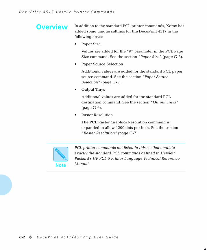
D o c u P r i n t 4 5 1 7 U n i q u e P r i n t e r C o m m a n d s
G-2 ❖ D o c u P r i n t 4 5 1 7 / 4 5 1 7 m p U s e r G u i d e
Overview In addition to the standard PCL printer commands, Xerox has
added some unique settings for the DocuPrint 4517 in the following areas:
• Paper Size
Values are added for the “#” parameter in the PCL Page
Size command. See the section “Paper Size” (page G-3).
• Paper Source Selection
Additional values are added for the standard PCL paper
source command. See the section “Paper Source Selection” (page G-5).
• Output Trays
Additional values are added for the standard PCL
destination command. See the section “Output Trays” (page G-6).
• Raster Resolution
The PCL Raster Graphics Resolution command is
expanded to allow 1200 dots per inch. See the section “Raster Resolution” (page G-7).
Note
PCL printer commands not listed in this section emulate
exactly the standard PCL commands defined in Hewlett Packard’s HP PCL 5 Printer Language Technical Reference Manual.
chapterg.frm Page 2 Friday, July 11, 1997 9:05 PM
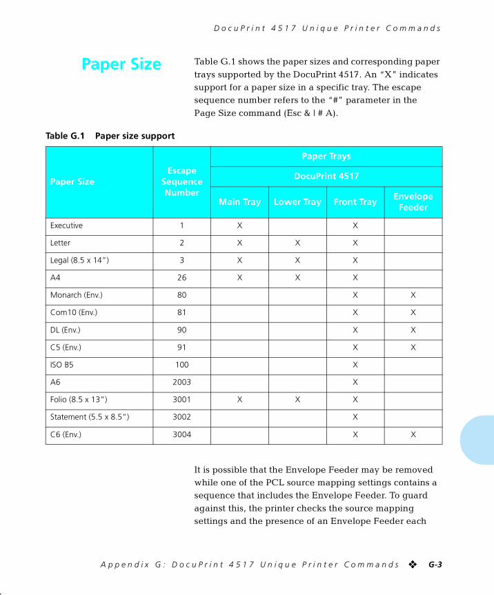
D o c u P r i n t 4 5 1 7 U n i q u e P r i n t e r C o m m a n d s
A p p e n d i x G : D o c u P r i n t 4 5 1 7 U n i q u e P r i n t e r C o m m a n d s ❖ G-3
Paper Size Table G.1 shows the paper sizes and corresponding paper
trays supported by the DocuPrint 4517. An “X” indicates support for a paper size in a specific tray. The escape sequence number refers to the “#” parameter in the
Page Size command (Esc & | # A).
It is possible that the Envelope Feeder may be removed while one of the PCL source mapping settings contains a sequence that includes the Envelope Feeder. To guard
against this, the printer checks the source mapping settings and the presence of an Envelope Feeder each
Table G.1 Paper size support
Paper SizeEscape
Sequence Number
Paper Trays
DocuPrint 4517
Main Tray Lower Tray Front TrayEnvelope
Feeder
Executive 1 X X
Letter 2 X X X
Legal (8.5 x 14”) 3 X X X
A4 26 X X X
Monarch (Env.) 80 X X
Com10 (Env.) 81 X X
DL (Env.) 90 X X
C5 (Env.) 91 X X
ISO B5 100 X
A6 2003 X
Folio (8.5 x 13”) 3001 X X X
Statement (5.5 x 8.5”) 3002 X
C6 (Env.) 3004 X X
chapterg.frm Page 3 Friday, July 11, 1997 9:05 PM
P a p e r S i z e
G-4 ❖ D o c u P r i n t 4 5 1 7 / 4 5 1 7 m p U s e r G u i d e
time the printer is powered on. If an Envelope Feeder is
not attached, any mapping that contains “Envelope Feeder” will be changed to “Front.” If an Envelope Feeder is attached to the printer again, the Envelope
Feeder will not be restored in any source mapping setting automatically. The Control Panel can be used to perform a “Reset Menus” or to select a new value for source
mapping.
chapterg.frm Page 4 Friday, July 11, 1997 9:05 PM
D o c u P r i n t 4 5 1 7 U n i q u e P r i n t e r C o m m a n d s
A p p e n d i x G : D o c u P r i n t 4 5 1 7 U n i q u e P r i n t e r C o m m a n d s ❖ G-5
Paper SourceSelection
PCL recognizes the six paper sources shown in Table G.2.
(These PCL paper sources may, or may not, appear in your software application, or they may appear under alternate names. Remember that these logical sources are mapped to
actual trays by the settings of Source Mapping (see page 2-19.)
† The character following the “&” in the command string is the lower case character “L.”
Table G.2 Six PCL paper sources
PCL Paper Source PCL Command† Alternate Names
Upper <Esc>& l1H Main Tray, Paper Tray, Paper Cassette
Manual <Esc>& l2H Front Tray, Manual Feed
Manual Envelope <Esc>& l3H Envelope Manual Feed
Lower <Esc>& l4H Lower Tray
Large Capacity <Esc>& l5H Paper Deck
Envelope Feeder <Esc>& l6H N/A
chapterg.frm Page 5 Friday, July 11, 1997 9:05 PM
D o c u P r i n t 4 5 1 7 U n i q u e P r i n t e r C o m m a n d s
G-6 ❖ D o c u P r i n t 4 5 1 7 / 4 5 1 7 m p U s e r G u i d e
Output Trays The output tray is selected with the standard PCL destination
command, but with additional values given in Table G.3 to address all the possible DocuPrint 4517 output trays. Selection of the collator output value causes each copy of the
output to use a different bin of the optional Mailbox/Collator, the first n bins for n copies (up to 10). The HP standard output value of 2 will be accepted for compatibility, and will use the
standard output tray.
† The character following the “&” in the command string is the lower case character “L.”
Table G.3 Output tray selection
Output Tray PCL Command†
Standard <Esc>& l1G
OCT <Esc>&l99G
Collator <Esc>&l100G
Mailbox bin 1 <Esc>&l101G
Mailbox bin 2 <Esc>&l102G
Mailbox bin 3 <Esc>&l103G
Mailbox bin 4 <Esc>&l104G
Mailbox bin 5 <Esc>&l105G
Mailbox bin 6 <Esc>&l106G
Mailbox bin 7 <Esc>&l107G
Mailbox bin 8 <Esc>&l108G
Mailbox bin 9 <Esc>&l109G
Mailbox bin 10 <Esc>&l110G
chapterg.frm Page 6 Friday, July 11, 1997 9:05 PM
D o c u P r i n t 4 5 1 7 U n i q u e P r i n t e r C o m m a n d s
A p p e n d i x G : D o c u P r i n t 4 5 1 7 U n i q u e P r i n t e r C o m m a n d s ❖ G-7
RasterResolution
The PCL Raster Graphics Resolution command (<Esc>*t#R) is
expanded to allow 1200 dots per inch. It also accepts negative arguments to indicate a resolution that applies in the fast-scan dimension only, in order to accommodate 1200x600
resolution.
chapterg.frm Page 7 Friday, July 11, 1997 9:05 PM
D o c u P r i n t 4 5 1 7 U n i q u e P r i n t e r C o m m a n d s
G-8 ❖ D o c u P r i n t 4 5 1 7 / 4 5 1 7 m p U s e r G u i d e
PCL MacroCommands
The DocuPrint 4517 supports downloading of PCL macros to
memory, optional PCMCIA card and or Hard Disk. The 4517 PCL Windows driver provides the capability to create and download macros which will work with most applications. In
addition, application specialists that develop tailored applications can use form creation packages or hand code macros and include the 4517 PCL macro download/delete
commands.
These commands should be used only by technical persons programming printer applications programs that involve
storing/deleting macros on the printer’s Hard Disk and/or PCMCIA card.
The 4517 uses custom PCL commands to download and
delete PCL macros to/from the optional Hard Disk and PCMCIA card. Standard PCL commands are used to download PCL Macros to memory, and to invoke the
downloaded Macros from any device via reference to the Macro ID#. In cases where a duplicate Macro number exists on the printer, the printer will access the Macro in priority
order as follows: Memory, PCMCIA Upper Card, PCMCIA Lower Card, Rigid Disk. However, to ensure consistent results, it is recommended to delete duplicate Macro ID#s
from the printer, prior to downloading a new Macro.
chapterg.frm Page 8 Friday, July 11, 1997 9:05 PM
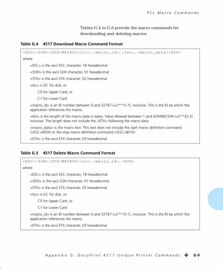
P C L M a c r o C o m m a n d s
A p p e n d i x G : D o c u P r i n t 4 5 1 7 U n i q u e P r i n t e r C o m m a n d s ❖ G-9
Tables G.4 to G.6 provide the macro commands for
downloading and deleting macros.
Table G.4 4517 Download Macro Command Format
<ESC><SOH><STX>MACROL<loc>,<macro_ id>,< len>,<macro_da ta><ETX>
where
<ESC> is the ascii ESC character, 1B hexadecimal
<SOH> is the ascii SOH character, 01 hexadecimal
<STX> is the ascii STX character, 02 hexadecimal
<loc> is DC for disk, or
C0 for Upper Card, or
C1 for Lower Card
<macro_id> is an ID number between 0 and 32767 (=2**15-1), inclusive. This is the ID by which theapplication references the macro.
<len> is the length of the macro data in bytes. Value allowed between 1 and 4294967294 (=2**32-2)inclusive. The length does not include the <ETX> following the macro data.
<macro_data> is the macro text. This text does not include the start macro definition command(<ESC>&f0X) or the stop macro definition command (<ESC>&f1X)
<ETX> is the ascii ETX character, 03 hexadecimal
Table G.5 4517 Delete Macro Command Format
<ESC><SOH><STX>MACROD<loc>,<macro_ id>,<ETX>
where
<ESC> is the ascii ESC character, 1B hexadecimal
<SOH> is the ascii SOH character, 01 hexadecimal
<STX> is the ascii STX character, 02 hexadecimal
<loc> is DC for disk, or
C0 for Upper Card, or
C1 for Lower Card
<macro_id> is an ID number between 0 and 32767 (=2**15-1), inclusive. This is the ID by which theapplication references the macro.
<ETX> is the ascii ETX character, 03 hexadecimal
chapterg.frm Page 9 Friday, July 11, 1997 9:05 PM
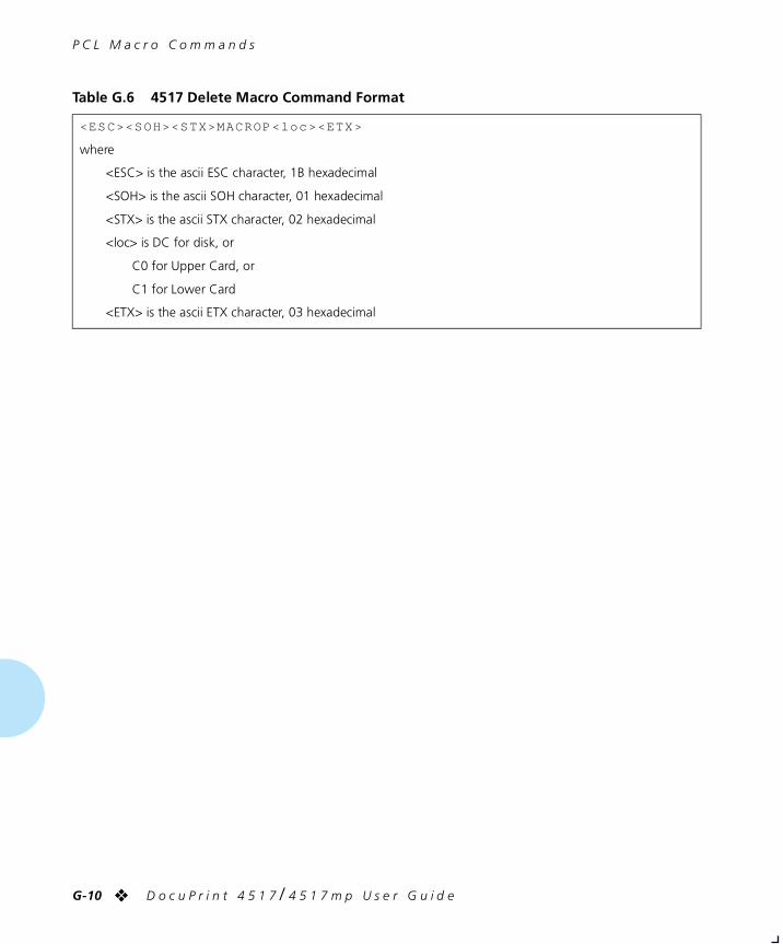
P C L M a c r o C o m m a n d s
G-10 ❖ D o c u P r i n t 4 5 1 7 / 4 5 1 7 m p U s e r G u i d e
Table G.6 4517 Delete Macro Command Format
<ESC><SOH><STX>MACROP<loc><ETX>
where
<ESC> is the ascii ESC character, 1B hexadecimal
<SOH> is the ascii SOH character, 01 hexadecimal
<STX> is the ascii STX character, 02 hexadecimal
<loc> is DC for disk, or
C0 for Upper Card, or
C1 for Lower Card
<ETX> is the ascii ETX character, 03 hexadecimal
chapterg.frm Page 10 Friday, July 11, 1997 9:05 PM
D o c u P r i n t 4 5 1 7 U n i q u e P r i n t e r C o m m a n d s
A p p e n d i x G : D o c u P r i n t 4 5 1 7 U n i q u e P r i n t e r C o m m a n d s ❖ G-11
Font Priority In cases where a duplicate font exists on the printer, the
printer will access the font in priority order as follows:
1. Soft
2. Upper Font Card
3. Lower Font Card
4. Disk
5. Resident
chapterg.frm Page 11 Friday, July 11, 1997 9:05 PM

G-12 ❖ D o c u P r i n t 4 5 1 7 / 4 5 1 7 m p U s e r G u i d e
chapterg.frm Page 12 Friday, July 11, 1997 9:05 PM

Appendix H
A p p e n d i x H : E n v i r o n m e n t a l S p e c i f i c a t i o n s ❖ H-1
Environmental Specifications AppendixH
chapterh.frm Page 1 Friday, July 11, 1997 9:06 PM

E n v i r o n m e n t a l S p e c i f i c a t i o n s
H-2 ❖ D o c u P r i n t 4 5 1 7 / 4 5 1 7 m p U s e r G u i d e
The XeroxCommitment toEnvironmental
Quality
Xerox Corporation is committed to an international program
to safeguard our environment by diverting certain products and materials from the solid waste stream. We do this by reusing serviceable components and remanufacturing
selected products.
To support this effort, we have made it easy for you to return selected printer equipment and empty print cartridges to
Xerox. We recondition the print cartridges and refill them with Xerox toner and developer. All products we manufacture meet our stringent performance standards.
The world-wide effort to remanufacture printer equipment and recall EP (print) cartridges benefits the environment and conserves our natural resources by reducing waste going into
our landfills. Besides, it makes good business sense for Xerox and Xerox customers. Please join us in this effort.
Acoustic NoiseFigures
On Standby (ROS Pause): 35dB(A)
Under Operation:
Continuous Sound: 49.5 dB(A)
chapterh.frm Page 2 Friday, July 11, 1997 9:06 PM
E n v i r o n m e n t a l S p e c i f i c a t i o n s
A p p e n d i x H : E n v i r o n m e n t a l S p e c i f i c a t i o n s ❖ H-3
FCC ComplianceStatement forUnited States
Users
Class B:
This equipment has been tested and found to comply with the limits for a Class B digital device, pursuant to Part 15 of the FCC Rules. These limits are designed to provide reasonable
protection against harmful interference in a residential installation. This equipment generates, uses, and can radiate radio frequency energy and, if not installed and used in
accordance with the instructions, may cause harmful interference to radio communications. However, there is no
guarantee that interference will not occur in a particular installation. If this equipment does cause harmful interference to radio or television reception, which can be
determined by turning the equipment off and on, the user is encouraged to try to correct the interference by one or more of the following measures:
• Reorient or relocate the receiving antenna.
• Increase the separation between the equipment and receiver.
• Connect the equipment into an outlet on a circuit different from that to which the receiver is connected.
• Consult the dealer or an experienced radio/television technician for help.
Shielded cables must be used with this equipment to maintain compliance with FCC regulations.
Caution: Changes or modifications not expressly approved by Xerox Corporation could void the user’s authority to operate the equipment.
chapterh.frm Page 3 Friday, July 11, 1997 9:06 PM
E n v i r o n m e n t a l S p e c i f i c a t i o n s
H-4 ❖ D o c u P r i n t 4 5 1 7 / 4 5 1 7 m p U s e r G u i d e
ComplianceStatement for
International Users
Canadian EME Regulations:
This digital apparatus does not exceed the Class B limits for radio noise emissions from digital apparatus set out in the radio interference regulations of the Canadian Department of
Communications.
Cet appareil numérique est conforme aux limites d’émission de bruits radioélectriques pour les appareils de Classe B
stipulées dans le Réglement sur le brouillage radioélectrique du Ministère des Communications du Canada.
European EME Regulations:
“The CE marking applied to this product symbolizes Rank Xerox Declaration of Conformity with the following applicable Directives of the European Union as of the dates
indicated:
January 1, 1995: - Council Directive 73/23/EEC amended by Council Directive 93/68/EEC, approximation of the laws of the member states related to low voltage equipment.
January 1, 1996: - Council Directive 89/336/EEC, approximation of the laws of the member states related to electromagnetic compatibility.
A full declaration, defining the relevant Directives and
referenced standards can be obtained from your Rank Xerox representative.”
chapterh.frm Page 4 Friday, July 11, 1997 9:06 PM
E n v i r o n m e n t a l S p e c i f i c a t i o n s
A p p e n d i x H : E n v i r o n m e n t a l S p e c i f i c a t i o n s ❖ H-5
Operational Safety Your Xerox equipment and supplies were designed and
tested to meet strict safety requirements. These include safety agency examination, approval, and compliance with established environmental standards.
Attention to the following notes ensures the continued safe operation of your equipment.
Always connect the equipment to a properly grounded power
source receptacle. If in doubt, have the receptacle checked by a qualified electrician.
WARNING: Improper connection of the equipment grounding conductor can result in electrical shock.
Always follow all warnings and instructions marked on, or supplied with, the equipment.
Always locate the equipment on a solid support surface with adequate strength for the weight of the machine.
Always exercise care in moving or relocating the equipment.
Always place the equipment in an area which provides adequate room area for ventilation and servicing.
Always use the materials and supplies specifically designed
for your Xerox equipment. Use of unsuitable materials may result in poor performance and, possibly, a hazardous situation.
Never use a ground adaptor plug to connect the equipment to
a power source receptacle that lacks a ground connection terminal.
Never attempt any maintenance function that is not
specifically described in this documentation.
Never obstruct ventilation openings. These are provided to prevent overheating.
Never install the equipment near a radiator or any other heat
source.
chapterh.frm Page 5 Friday, July 11, 1997 9:06 PM
E n v i r o n m e n t a l S p e c i f i c a t i o n s
H-6 ❖ D o c u P r i n t 4 5 1 7 / 4 5 1 7 m p U s e r G u i d e
Never override or “cheat” electrical or mechanical interlock
devices.
Never push objects of any kind into the ventilation openings.
Never operate the equipment if you notice unusual noises or odors. Disconnect the power cord from the power source
receptacle and contact your dealer or Xerox / Rank Xerox to correct the problem.
If you need any additional safety information concerning the
equipment or materials, contact your dealer or Xerox / Rank Xerox.
WARNING: Use of controls, adjustments, or performance of
procedures other than those specified herein may result in a hazardous radiation exposure.
This product will produce less than 0.1 ppm ozone during normal operation. The ozone produced is dependent on copy
volume and is heavier than air. Providing the proper environmental parameters as specified by Xerox will ensure that concentration levels meet safe limits.
If additional information concerning ozone is needed, request the Xerox publication (600P83222), “Ozone,” by calling in the USA 1-800-828-6571.
chapterh.frm Page 6 Friday, July 11, 1997 9:06 PM
E n v i r o n m e n t a l S p e c i f i c a t i o n s
A p p e n d i x H : E n v i r o n m e n t a l S p e c i f i c a t i o n s ❖ H-7
Laser Safety WARNING: Use of controls or adjustments or performance of
procedures other than those specified herein may result in hazardous light exposure.
This equipment complies with appropriate safety standards.
With specific regard to lasers, the equipment complies with
laser product performance standards set by governmental, national, and international agencies as a Class 1 laser
product. It does not emit hazardous light as the beam is totally enclosed during all phases of customer operation and maintenance.
When you perform various operator functions, laser danger
labels may be visible. These labels are for your dealer or service technician and are placed on or near panels, or shields, which require a tool for removal. THESE PANELS
ARE NOT TO BE REMOVED BY USERS OF THE PRINTER. THERE ARE NO USER SERVICEABLE AREAS INSIDE THESE COVERS.
Laser SafetyWarning forFinland and
Sweden
Luokitus on tehty standardin EN 60825 mukaisesti
Klassningen är gjord i enlighet met standarden EN 60 825
LUOKAN 1 LASERLAITEKLASS 1 LASER APPARAT
VAROITUS!
Laitteen käyttäminen muulla kuin tässä käyttöohjeessa mainitulla tavalla saattaa altistaa käyttäjän turvallisuusluokan 1 ylittävälle näkymättömälle
lasersäteilylle.
VARNING!Om apparaten används på annat sätt än i denna
bruksansvisning specficerats, kan användaren utsättas för osynlig laserstrålning, som överskrider gränsen för laserklass 1.
chapterh.frm Page 7 Friday, July 11, 1997 9:06 PM

H-8 ❖ D o c u P r i n t 4 5 1 7 / 4 5 1 7 m p U s e r G u i d e
chapterh.frm Page 8 Friday, July 11, 1997 9:06 PM
Index
I n d e x ❖ IX-1
Numerics
500-sheet Paper Deck and Cassette
Installing C-24 to C-30Ordering A-2Overview 1-9Removing C-31 to C-32
A
Auto Continue option D-3
Auto Job End option D-3
B
Bias Transfer Roll, see Fuser cartridge
Bin Full option D-3
Bin N option D-3
C
Cancel PS Job option D-4
Collator option D-4
Config. sheet option D-4
Configuration SheetControl Panel message 6-8Control Panel option D-4
Overview 1-8
Control PanelKeys 3-4 to 3-5
Down 3-5Enter 3-5Esc 3-4Form Feed 3-4Menu 3-4Online 3-4Reset 3-4Up 3-5
Location 1-5Menus
Ethernet Menu 3-22, 3-23Interface Menu 3-20 to 3-24Language Menu 3-12LocalTalk Menu 3-22, 3-23Mailbox Menu 3-13Main Menu 3-11Parallel Menu 3-21PCL Emulat Menu 3-14 to
3-16PostScript Menu 3-17 to
3-19Reset Menu 3-27System Menu 3-25Test Menu 3-26Token Ring Menu 3-22,
3-24Messages 6-6 to 6-26Navigating 3-6 to 3-10
index.frm Page 1 Friday, July 11, 1997 9:08 PM
D
IX-2 ❖ D o c u P r i n t 4 5 1 7 / 4 5 1 7 m p U s e r G u i d e
Copies option D-4
D
Default Source option D-5
Default Tray option D-5
Defaults option D-4
Demo PageOverview 1-8
Demo Page option D-5
Deutsch optionLanguage Menu 3-12
Disable Password option D-5
Disk drive, see Hard drive
Disk Spooling option D-5
Disk spooling, see Hard drive
DocuPrint 4517Control panel location 1-5Front cover location 1-5Front tray location 1-5Main tray location 1-5Maintaining
Cleaning 1-13Recycling EP cartridge 1-13Replacing EP cartridge 1-13Replacing fuser cartridge 1-14
Memory considerations 1-11Memory expansion 1-10Memory requirements 1-12Network ports location 1-5Option interface cover location 1-5Parallel port location 1-5PCMCIA card slots location 1-5Power inlet location 1-5Power switch location 1-5Printer components 1-5Rear cover location 1-5Specifications F-2 to F-3Standard output tray location 1-5Technical support 1-15Transporting 1-16
DocuPrint 4517mp 1-3Also see DocuPrint 4517
Down key 3-5
Downloading, see Hard drive
Drivers, see Printer drivers
Duplex feeder, see Duplex module
Duplex module 2-29 to 2-30Installing C-21 to C-22Ordering A-2Overview 1-9Paper jams 6-32Paper orientation 2-30Paper sizes 2-29Paper weights 2-29Removing C-23
Duplex option D-6
Duplex printing, see Duplex module
E
Edge to Edge option D-6Overview 1-7
Enable Password option D-6
English optionLanguage Menu 3-12
Enter key 3-5
Env Feeder Size option D-6
Envelope Feeder 2-27 to 2-28Envelope jams 6-31Envelope sizes 2-3Installing C-43 to C-45Loading envelopes 2-28Ordering A-2Removing C-46 to C-47Using 2-27 to 2-28
EP cartridge A-2Paper jams 6-33Recycling 1-13Replacing 1-13, B-2 to B-4
Error Messages 6-6 to 6-26
Esc key 3-4
Español optionLanguage Menu 3-12
Ethernet card, see XNIC-E’NET
Ethernet Menu 3-22, 3-23Auto Job End option D-3
index.frm Page 2 Friday, July 11, 1997 9:08 PM
F
I n d e x ❖ IX-3
Lang. Sensing option D-9Port Enable option D-13Port Timeout option D-13System Language option D-17
F
Fmt LwrMacroCard option D-7
Fmt UprMacroCard option D-7
Font cardsInstalling C-48Ordering A-16Removing C-48
Font Number option D-7
Font Source option D-7
FontsDownloading 5-4PCL E-2PostScript E-4Printing PCL Font List E-3
Form Feed key 3-4
Form Length option D-8
Format the Disk option D-8
Français optionLanguage Menu 3-12
Front coverLocation 1-5
Front trayLoading 2-11 to 2-12Location 1-5Paper jams 6-29Paper orientation 2-9 to 2-10Paper sizes 2-3
Front Tray Size option D-8
Fuser cartridgeOrdering A-2Replacing 1-14, B-5 to B-9
H
Hard disk, see Hard drive
Hard drive 5-2 to 5-5Disk spooling 5-2Downloading 5-2, 5-4Formatting 5-3
Installing C-16 to C-18Ordering A-3Print spooling 5-2Removing C-19 to C-20State saving 5-2
Hex Dump option D-8
I
Interface Menu 3-20 to 3-24
Italiano optionLanguage Menu 3-12
J
Jam Recovery option D-9
L
Lang. Sensing option D-9
Language 3-12
Language Menu 3-12Options
Deutsch 3-12English 3-12Español 3-12Français 3-12Italiano 3-12Portugués (BRA) 3-12
Language sensingOverview 1-7
LocalTalk card, see XNIC-L’TALK
LocalTalk Menu 3-22, 3-23Port Enable option D-13Port Timeout option D-13
Lower trayAdjusting size 2-8Capacity 2-5Ordering A-2Overview 1-9Paper jams 6-30Paper orientation 2-5 to 2-6Paper sizes 2-3
M
Macro cardsInstalling C-48Ordering A-2
index.frm Page 3 Friday, July 11, 1997 9:08 PM
N
IX-4 ❖ D o c u P r i n t 4 5 1 7 / 4 5 1 7 m p U s e r G u i d e
Removing C-48
MacrosDownloading 5-4
Mailbox Menu 3-13Bin Full option D-3Bin N option D-3Collator option D-4Disable Password option D-5Enable Password option D-6
Mailbox/Collator 2-19 to 2-25Bin numbering 2-20Capacity 2-20Installing C-38 to C-40Opening bins 2-25Ordering A-2Overview 1-9, 2-19Paper jams 6-32Paper sizes 2-3Removing C-41 to C-42Using passwords 2-20 to 2-25
Disabling 2-23 to 2-24Enabling 2-21 to 2-22
Main Menu 3-11
Main trayAdjusting size 2-7Capacity 2-5Location 1-5Ordering A-2Paper jams 6-29Paper orientation 2-5 to 2-6Paper sizes 2-3
Manual Size option D-10
MemoryConsiderations 1-11Expansion 1-10Requirements 1-12See also SIMMs
Memory Check option D-10
Menu key 3-4
Messagesalso see Control PanelError 6-6 to 6-26
Multi-sheet Bypass Tray, see Front tray
N
Network portsLocation 1-5
O
OCT 2-26Capacity 2-26Installing C-33 to C-35Ordering A-2Overview 1-9, 2-26Paper jams 6-31Paper sizes 2-3Removing C-36 to C-37Using 2-26
Offset Catch Tray, see OCT
Online key 3-4
Option interface coverLocation 1-5
Ordering A-2
Orientation option D-11
Output Bin option D-11
P
Page Protection option D-11
Page Size Cont option D-11
PaperJams 3-4, 6-28 to 6-34
Causes 6-28Clearing 6-28 to 6-34
Sizes 2-3Storage of 2-4
Paper Size option D-12
Parallel MenuAuto Job End option D-3Lang. Sensing option D-9Overview 3-21Port Enable option D-13Port Timeout option D-13System Language option D-17
Parallel portLocation 1-5
Password optionMailbox Menu
Password option D-12
index.frm Page 4 Friday, July 11, 1997 9:08 PM
R
I n d e x ❖ IX-5
PCL Emulat Menu 3-14 to 3-16Copies option D-4Default Source option D-5Duplex option D-6Edge to Edge option D-6Env Feeder Size option D-6Font Number option D-7Font Source option D-7Form Length option D-8Front Tray Size option D-8Jam Recovery option D-9Orientation option D-11Output Bin option D-11Page Protection option D-11Page Size Cont option D-11Paper Size option D-12Pitch option D-13Point Size option D-13Print Quality option D-14Resolution option D-16Source Mapping option D-16State Saving option D-16Symbol Set option D-17
PCL Font ListOverview 1-8
PCL Font List option D-12
PCMCIA cardsInstalling C-48Ordering A-2, A-16Removing C-48Slot location 1-5
Perform Enhance option D-12
Pitch option D-13
Point Size option D-13
Port Enable option D-13
Port Timeout option D-13
Portugués (BRA) optionLanguage Menu 3-12
PostScriptFonts E-4Installing C-10 to C-12Removing C-13 to C-15Upgrade 1-8
PostScript Font ListOverview 1-8
PostScript Menu 3-17 to 3-19Copies option D-4Default Tray option D-5Duplex option D-6Env Feeder Size option D-6Jam Recovery option D-9Manual Size option D-10Output Bin option D-11Page Protection option D-11Print Errors option D-14Print Quality option D-14PS Font List option D-14Resolution option D-16State Saving option D-16Tray Switching option D-18
PostScript optionOrdering A-3
Power inletLocation 1-5
Power Saver modeOverview 1-6
Power Saver option D-14
Power switchLocation 1-5
Print cartridge, see EP cartridge
Print Density option D-14
Print Errors option D-14
Print Quality option D-14Overview 1-6
Print quality problems 6-35 to 6-41
Print spooler, see Hard drive
Printer drivers 4-2 to 4-3Ordering A-5 to A-9PCL 5e Emulation 4-2PostScript 4-3
PS Font List option D-14
R
Rear coverLocation 1-5
Reset All option D-15
Reset Ethernet option D-15
Reset key 3-4
index.frm Page 5 Friday, July 11, 1997 9:08 PM
S
IX-6 ❖ D o c u P r i n t 4 5 1 7 / 4 5 1 7 m p U s e r G u i d e
Reset LocalTalk option D-15
Reset Menu 3-27Cancel PS Job option D-4Reset All option D-15Reset Ethernet option D-15Reset LocalTalk option D-15Reset Menus option D-15Reset Printer option D-15Reset Token Ring option D-15
Reset Menus option D-15
Reset Printer option D-15
Reset Token Ring option D-15
Resolution option D-16
S
SIMMs 1-10Installing C-5 to C-7Ordering A-3Removing C-8 to C-9
Source Mapping option D-16
Source mapping, see Tray switching
Standard output trayLocation 1-5Paper sizes 2-3
State Saving option D-16Overview 1-8
State saving, see Hard drive
Symbol Set option D-17
System Language option D-17
System Menu 3-25Auto Continue option D-3Defaults option D-4Disk Spooling option D-5Hex Dump option D-8Perform Enhance option D-12Power Saver option D-14Print Density option D-14
T
Technical support 1-15
Test Menu 3-26Config. sheet option D-4Demo Page option D-5
Fmt LwrMacroCard option D-7Fmt UprMacroCard option D-7Format the Disk option D-8Memory Check option D-10PCL Font List option D-12Test Print option D-18
Test PrintOverview 1-8
Test Print option D-18
Token Ring card, see XNIC-T’RING
Token Ring Menu 3-22, 3-24Auto Job End option D-3Lang. Sensing option D-9Port Enable option D-13Port Timeout option D-13System Language option D-17
Toner, see EP cartridge
Tray switching 2-13 to 2-18Overview 1-7PCL 2-14 to 2-18PostScript 2-13
Tray Switching option D-18
TroubleshootingControl Panel messages 6-6
TrueResOverview 1-6
U
Up key 3-5
X
XNIC-E’NETInstalling C-50 to C-53Ordering A-4Removing C-54 to C-55
XNIC-L’TALKInstalling C-50 to C-53Ordering A-4Removing C-54 to C-55
XNIC-T’RINGInstalling C-50 to C-53Ordering A-4Removing C-54 to C-55
index.frm Page 6 Friday, July 11, 1997 9:08 PM