Embed Size (px)
Citation preview

(NASA-CR-198818) THE FUTURE OF
SPACE IMAGING. REPORT OF A
COMMUNITY-BASED STUDY OF AN
ADVANCED CAMERA FOR THE HUBBLE
SPACE TELESCOPE Final Technical
Report (Space Telescope ScienceInst.) 150 p
N95-31364
Unclas
G3/89 0055789
TheFuture ofSpaceImaging
hen Lyman Spitzer first proposed a great,earth-orbiting telescope in I946, the nudear
energy source of stars had been known for just six
years. Knowledge of galaxies beyond our own and
the understanding that our universe is expanding
were only about twenty years of age in the human
consciousness. The planet Pluto was seventeen.
Quasars, black holes, gravitational lenses, and detection of the Big Bang were
still in the future--together with much of what constitutes our current un-
derstanding of the solar system and the cosmos beyond it. In I993, forty-
seven years after it was conceived in a forgotten milieu of thought, the
Hubble Space Telescope is a reality.
Today, the science of the Hubble attests to the forward momentum of
astronomical exploration from ancient times. The qualities of motion and
drive for knowledge it exemplifies are not fixed in an epoch or a generation:
most of the astronomers using Hubble today were not born when the idea of
it was first advanced, and many were in the early
stages of their education when the glass for its mirror
was cast,
The commitments we make today to the future
of the Hubble observatory will equip a new genera-
tion of young men and women to explore the astro-
nomical frontier at the start of the 2I st century.
/
The Future of SpaceImaging
Report of a Community-Based Study
of_nAdvanced Camera
fortheHubble Space Telescope
Edited by Robert A. Brown
Space Te[escope Science bmitute
3700 5hn Martin Ddve
Ba[timore, Ma_[a,ld 21218
October J9_

II!
Authorship
This report is the product of the Future of Space hnaging study' and
of the subsequent preparation of the proposal of the Advanced Camera
to the ESA M3 competition 2, in which the following people participated
or to which they contributed. It was our privilege to conduct this study
and author this report on behalf of the international community of as-
tronomers. We express our particular gratitude to our many colleagues
who responded to the community survey.
James Beletic'
Pierre Bely'
J. Chris Blades _
Robert Brown I'2
Christopher Burrows'
Mark Clampin ''2France Cordova 2
Edward Cheng _
James Crocker t'z
Greg Davidson
Jean Michel Deharveng 2
Robert Fosbury _'2
John Hoessel _
John Huchra ''2
Garth lllingworth z
Roll-Peter Kudritzki z
Tod Lauer'
Michael Lesser ''_
Edwin Lob _
Duccio Macchetto 2
Aden & Marjorie Meinel'
George Miley 2
Georgia Institute of Technology
Space Telescope Science Institute, ESA
Space Telescope Science Institute
Space Telescope Science Institute
Space Telescope Science Institute, ESA
Space Telescope Science Institute
Pennsylvania State University
Goddard Space Flight Center
Space Telescope Science Institute
National Aeronautics and Space Administration
Laboratoire d'Astronomie Spatiale, Marseille
ST-European Coordinating Facility, ESA
University of Wisconsin
Center for Astrophysics
Lick Observatory
University of Munich
National Optical Astronomy Observatories
Steward Observatory
Michigan State University
Space Telescope Science Institute, ESA
Jet Propulsion Laboratory
Leiden Observatory
PRECEDING PAGE BLANK NOT FI,LMEFPAC__.iL__ ii': f_£,_l!C:,_!_[_i.f_Ai:K

Jv FOSI: Frontiers of Space Imaging
Wal-rcll moos 1
Jeremy Mould'
Susan Ne_
Francesco Paresce z
Ronald Polidan _
Michel Sffisse z
Francois Schweizer'
Donald York _
Johns Hopkins University
California Institute of Technology
Goddard Space Flight Center
Space Telescope Science Institute, Torino, ESA
Goddard Space Flight Center
Laboraroire d'Astronomie Spatiale, Marseille
Carnegie Institution of Washington
University of Chicago

Preface
In March I99Z, the National Aeronautics and Space Administration
(NASA) Program Scientist for Hubble Space Telescope (HST) invited
the Space Telescope Science Institute (ST Scl) to conduct a commu-
ni[y-based study of an Advanced Camera (AC), which would be in-
stalled on a scheduled HST servicing mission in [999. The study had
three phases: a broad community survey of vicws ola the candidate sci-
ence program and required performance of the AC, an analysis of tech-
nical issues relating to its implementation, and a panel of experts to for-
mulate conclusions and prioritize recommendations. An oral report was
delivered in December r99z, at which time NASA made a second re-
quest to ST ScI, to assist in preparing a proposed for the AC on behalf'of
the astronomical community to the European Space Agent T (ESA) (.'_all
Jbr Missio,z Ideas oF26 November i992 ("M3 competition.") A joint US-
ESA science team was formed fbr this purpose, and the proposal was
submitted in May i993. This report--- The l_)alo'e of Space [magip_-is a
compilation of the results of'both the study and ESA proposal.

VII
Introduction
The Hubble Space Telescope (HST) is a cooperative program of the
European Space Agency (ESA) and the U.S. National Aeronautics and
Space Administration (NASA) to operate a long-lived observatory, in
space for the benefit of the international astronomical community. The
three years since the launch of liST in 199o have been momentous, with
the discovery of spherical aberration and the search for a practical solu-
tion. HST was designed for servicing in orbit by the Space Shuttle.
NASA and ESA are now preparing intensively for the first shuttle repair
mission scheduled for December 1993, which should obviate the effects
of spherical aberration and restore the functionality expected for HSTat launch.
Despite spherical aberration, hundreds of astronomers around the
world are analyzing HST data and reporting their discoveries. The earl),
results of HST are outstanding, as is illustrated by the recently published
proceedings of an international conference, Science with the Hubble
Space Telescope.' The HST program of astronomical research is un-
matched by any ground-based telescope, and it refreshes the original vi-
sion of what could be achieved by a great telescope unlettered by the
Earth's atmosphere--a vision postponed briefly but not foreclosed by
spherical aberration.
HST is now at a crossroads with respect to the second half of its de-
sign lifetimeIthe period after I997, when an advanced spectrograph
and a near infrared camera will be installed on the second servicing mis-
sion. In 1999, a third servicing mission will be required to restore the
spacecraft orbit, which decays due to atmospheric drag. Owing to the
long development time for space-qualified instruments, now is the time
to make critical decisions with respect to what scientific instrument can
or should be installed during the 1999 servicing mission. This instrument
must be started now to be ready on time in I999.
Over the past year and a half, in consultation with the international
PRECEDING PAGE BLANK NOT FW..MEJ_ GE V_ INTENTIONALLYBLA/VK
VIII FOSI: Frontiers of Space hnaging
astronomical community, we have studied the issue of what best can be
done with the I999 instrument opportunity. We have asked if there is
still a role for HST at the turn of the century. The answer is clearly: Yes/
We are convinced that HST, properly instrumented, will make unique
and important astronomical discoveries into the 2I_t century. This is be-
cause no ground-based telescope, no matter how large nor how well
equipped with adaptive optics, will match HST in terms of wavelength
coverage and image quality over a wide field.
We have asked what type of instrument will provide the greatest sci-
entific benefit to astronomers. We are convinced that it should be a cam-
era because otherwise an adequate optical and ultraviolet imaging capa-
bility will not be assured in 1999. Furthermore, it should be advanced
because detector and computer technology is now capable of deriving
full value from a 2.4 m diffraction-limited telescope in space.
What combination of scientific programs should define the priorities
for the technical performance of the Advanced Camera (AC)? The
breadth and depth of the highly competitive HST imaging science program.
We have assessed the imaging tasks astronomers have proposed for or
desired from HST, and we believe the most valuable 1999 instrument
would be a camera with both near ultraviolet/optical (NUVO) and far
ultraviolet (FUV) sensitivity, and with both wide field and high resolu-
tion options.
This report puts forth the scientific case and the technical basis for an
AC. It lays the groundwork for a Phase A study to assure feasibility, de-
termine cost and schedule considerations, and inform an Announce-
ment of Opportunity for the astronomical community to participate in
the development of the AC.
1. ST-ECF/STScl Workshop: Science with the Hubble Space Telescope, Pro-
ceedings, eds. P. Benvenuti and E. Schreier, (Munich: European South-
ern Observatory, i992.)
Contents
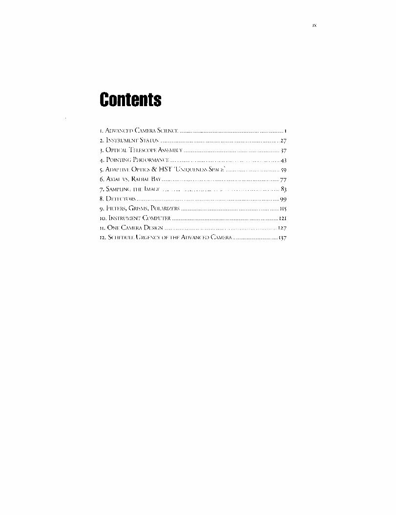
[. AD\:AN(Zlil) CAME1L,X SCIt,,NCE ................................................................................... 1
z. IN,_Tt',UMEN'r S']'ATU_; ................................................................................................ Z 7
3. Ol"l'l(:al, TH jsS(:OPr ASS_:.Mt_I Y. ............................................................................ 37
4- POINIIN(; PH_,FOI_,MANCE ........................................................................................ 43
5. AI)APTIVI", OIrI'ICS & HST 'UNIQUENF, SS SI'A(IF,'. .......................................... 59
6. Axial vs. RADiAl. BAY..............................................................................................77
7. SAMI'I,IN(; [ui_: IMA(ai ...............................................................................................83
8. Dvrt_cl_()Rs .................................................................................................................. 99
9. FIl,Il-l(s, GRISMS, P()I.ARIZEI(S .............................................................................. II 5
IO. [NNFRUMENT COivlI'UTER ..................................................................................... IZl
n. ONI_ C,_ML:J_aDt!.sk;N .......................................................................................... I27
I2. NCI IEDUI,F, UR( ;ENCY OF THF AIIVANCED CAMI',RA .................................... ]37


1, AdvancedCameraScience
Today, astronomers have at their disposal or see on the hori-
zon--a variety of telescopes and instruments, in space
and on the ground, operating at a wide range of wavelengths.
Given this variety, as well as the intense competMon for resources to
start new projects, we have been mindfid that a solid scientific case
is needed to support fitture investments in Iqubble Space Telescope
(HST)--an observatory conceived in the x94os, desig_wd and built
in the I97os, and now operational in the x99os. For this reason, we
have developed the issue of whether the Advanced Camera (AC)
should be built, and if so, what its characteristics must be to assure
it will provide" valuable capabilities not duplicated by other
ground-based or space-based observatories.
he great potential of the Hubble Space Telescope (HST) is con-
centrated in two extremely important capabilities: (I) the cover-
age of wavelengths inaccessible from the ground and (z) su-
perb, stable images. HST's superior image quality consists of two as-
pects: low image wings, and a wide field of view (FOV).
Ground-based telescopes--even m m class telescopes with adaptive
optics---cannot rival the ensemble of advantages of space imaging at op-
tical and ultraviolet wavelengths. (See chapter 5.) However, HST itself
will achieve this potentiality only when the planned corrections for
spherical aberration are in place--and then, completely, only when a
camera instrument takes full advantage of the quality wavefront the
HST telescope optics deliver to the focal surface.
HST's outstanding capability for imaging is essential for two of its
three 'Key Projects', which are critical astronomical programs singled
out by an international panel of astronomers prior to launch. Further-
more, imaging requirements that demanded what uniquely HST can
provide comprised the justification for a major fraction of the initial
General Observer (GO) and Guaranteed Time Observer (GTO) sci-
ence programs. And even with the spherical aberration problem, a sig-

2 FOSI:FrontiersofSpaceImaging
nificantfractionof thesciencealreadydonein thefirstthreeyearsofHSToperations--andthegreatbulkof thedatavolumethathasac-crued-havecomefromHST'sinitialcomplement of cameras. As of
April I, I993, HST had acquired 8,65I astronomical images, of which
6,o6_ were obtained with the Wide Field Planetary Camera (WFPC)
and 2,59o with the Faint Object Camera (FOC).
I.I SURVEY OF CANDIDATE SCIENCE PROGRAM
We have examined the ultraviolet, optical, and near infrared imaging
science programs that could and would be done with HST. We put par-
ticular emphasis on those scientific projects that could be best or only
addressed by HST and an Advanced Camera (AC). Input was solicited
from the international community and from individual experts; sample
programs were selected from the community input as well as an exami-
nation of the accepted proposals from the first three years of HST opera-
tions. Each research area was examined to determine (I) what camera ca-
pabilities would be required to make the necessary observations, (2)
whether ground-based capabilities might have advanced sufficiently to
solve nearly or completely the astrophysical problem before the year
2ooo, and (3) what impact HST observations would or could have on
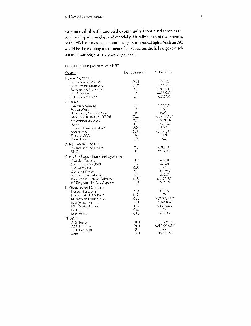
the solution and on the field in general. The list of such projects is given
in table H, along with our assessment of the camera characteristics (field,
preferred wavelength coverage, time resolution, apodization, filtration)
required to address the scientific issues squarely.
The list of scientific programs and opportunities given in table i.i is
extensive. It argues that the advantages of space imaging are substantial,
notably because o_ 0) the access to ultraviolet wavelengths, blocked at
ground-based observatories, which permits the study of energetic phe-
nomena and highly ionized regions; (2) the dark sky in the near infrared,
uncontaminated by OH atmospheric emission, which permits more
sensitive investigations of redshifted, reddened, or cooler objects; (3) the
stable, superb image quality at all wavelengths, over a wider FOV than at
ground-based sites, which generally provides a factor of Io gain in acuity
or factor of Ioo gain in spatial information; and (4) the ability to sample
flexibly in time, including continuous viewing in some parts of the sky,
plus the certainty of clear weather, which allows variable phenomena to
be discovered or critically examined.
The conclusion we have drawn from table l.I is that an AC would be
*. Advanced Camera Science 3
extremely valuable if it assured the community's continued access to the
benefits of space imaging, and especially if it fully achieved the potential
of the HST optics to gather and image astronomical light. Such an AC
would be the enabling instrument of choice across the full range of disci-
plines in astrophysics and planetary science.
Table 1.1.imaging science with HST
Programs Bandpasses Other Char
1,Solar SystemTime Variable Studies O,U,I H,W,N,S
Atmospheric Chemistry U,I,Q N,W,H,S
Atmospheric Dynamics 0,1 W,N,S,O.01Small Bodies 0 W,C,R,O.Q1
Extrasolar Planets Q,I C,O.01,R
2, Stars
Planetary Nebulae U,O O.Q1,G,NStellar Winds U,Q C,N,P
High Energy Sources, C_s U S,W,P
Star Forming Regions, YSO'S O,I,U W.C,O.Q1,N,P
Protoplanetary Disks Q,U,I C,O.01,P,RNovae U,Q,I O.01,N,C
Massive Luminous Stars U,O,I Nl,O_01
Astrometry O,I,U W,0.03,0.01Pulsars, OVV's U,Q S,N
Brown Dwarfs I,Q W,C
3. Interstellar Medium
H [i Regions - structure O,U W,N,Q.03SNR's U,Q W,N,Q.01
4. Stellar Populations and SystemsGlobular Clusters U,O W,O.Ol
Galactic Center (BW) 1,0 W,O.01
The Galaxy Halo Q,U,I W
Giant H II Regions O,U O.Ol,W,RGC's in other Galaxies O,U W,Q.01
Populations in other Galaxies O,U,I W,O.O1,N,G
HR Diagrams, IMF's, UV upturn U,O W,O.Q3
5. Galaxies and ClustersNuclear Structure Q,U Q.Q1,N
Integrated Stellar Pops U,O,i WMergers and Starbursts O,U,I W,Q.Q3,N,T,P
ISM(SNR,PN) O,U O.03,N,WICM (Cooling Flows) U,O W,N,T,O.03Evolution Q,U,I W
Morphology Q,I,U W,O.05
6. AGN'sAGN Hosts I,U,O C,T,N,O.Q1,P
AGN Environs Q,U,I W,N,Q.O3,C,T,P
AGN Evolution 0,1 W,G
Jets U,O,I C,P,O.O1,W,T

4 FOSI: Frontiers of Space Imaging
Nearby AGN
7. Cosmology
Distance Scale
QSO Absorbers
Primeval Galaxies
Galaxy CountsGravitational Lenses
SNe, Ho, %
Radio/X-ray ID's/IRSource Sizes
Large Scale Structure
Key:
BandpassesU* Far Ultraviolet (FUV), 1100/_ to 2500
0 Near UV/Opticai (NUVO),2500/_ to 10,000/_
i Near IR, 10,000 to 28,000 )_
Camera CharacteristicsW Wide field needed
D Day or longer time resolution neededH Hour time resolution neededM Minute time resolution
desirable
U,O,I T,P,O.O1,C,G,H
O,i,U W,D,H,Q.Q3
O,U T,W,G,O.03
I,O,U W,N,TO,I,U W
O,U D,M,W,O.O1,G0 W,D
O,U,I W,D
O,U 0.01
0,1 W
C Coronographic mode neededN Narrow band filters needed
T Tunable filters desirable
P Polarization measurements.
S Seconds or better time res. needed R High dynamic range desirable
G Grism mode needed 0.01, 0.03 Resolution needed, arcsec
*Calls for a "solar blind' detector for FUV, i.e., one that is insensitive to or blocked
against longer wavelength ultraviolet and visible light. Without such blocking, the FUV
signal would be swamped.
I.Z PERFORMANCE PRIORITIES FOR THE AC
We assessed what technical performance the AC should have to ad-
dress the candidate science program to the fullest feasible extent. We as-
signed priorities to those capabilities based on judgements that sought to
balance depth on some important problems with breadth corresponding
to the wide range of astronomical interests. In doing so, we recognized
that the HST community is widely ranging yet supportive of focused
progress on fundamental problems. On this basis, we recommend these
priorities:
• Highest priority is both (I) a wide-field near-ultraviolet/optical
(NUVO) mode, 2oo"x zoo" nominal field of view, half critical sam-
piing at 5500 A and (2) a high-resolution far ultraviolet (FUV) mode,
preferably solar blind, 12.5" x I2.5" nominal field of view, critical sam-
piing at I8OO A.
• Second priority is a high-resolution NUVO mode, 5o" x 50" nomi-
nal field of view, critical sampling at 5500 A. This mode should include a
coronographic option if the impact on efficiency is acceptable.

*.Advanced Camera Science 5
• Tbirdpriorigy is either (i) a wide-fleld FUV mode, 50" x 50" or
greater nominal field of view, half critical sampling at _8oo A, or (2) an
independent NUVO coronographic mode if this mode is implemented
separately from the high-resolution NUVO mode.
1.3 SPECIFIC AC SCIENTIFIC PROGRAMS
With confidence in the forgoing assertions about the general utility
of an AC with the stated performance specifications, we have selected
seven specific fields to illustrate the particular benefits of the AC:
• Planetary atmospheres
• Protoplanetary disks
• Stellar chromospheres
• Stellar populations
• Active galactic nuclei
• Galaxies and galaxy clusters
• The cosmological model
These sdentific topics are seven important and unique areas of op-
portunity for observations with the AC on HST. In general, substantial
progress on these critical programs will require both the imaging capa-
bilities of the AC and complementary observations, such as spectroscopy
from ground-based telescopes or measurements at longer or shorter
wavelengths by other spacecraft.
1.3.I PLANETARY ATMOSPHERES
For planetary observations, the customary advantages of space imag-
ing are compounded with the synoptic perspective of earth orbit, which
permits flexibly timed observations to address the variability of planetary
phenomena and to accommodate the effects of planetary rotation. In
this way, HST and the AC will provide a unique and valuable comple-
ment to space probes, which provide detailed measurements limited in
time and place, and to ground-based studies, which are limited in time,
wavelength, and spatial resolution.
The critically sampled NUVO mode of the AC will permit the glo-
bal atmospheres of Mars, Jupiter, Saturn, Uranus, and Neptune to be
studied with unprecedented acuity. Table 1.2 restates the specifications
of this mode in planetary terms. Figure LI illustrates the resolution in the
case of Jupiter.
For wind studies on Jupiter and Saturn, these performance improve-

6 FOSI: Frontiers of Space Imaging
ments will permit (I) more reliable measurements, resulting from the ability
to identify more individual tracers (improved statistics, more precise po-
sitions); (2) better access to convective features (smaller features at lower
contrast levels); and (3) greater sensitivity to vertical structure (more pre-
cise coordinates especially near the limb). (See Beebe et al., I989.)
During a disturbed phase on Jupiter or Saturn, the rapid framing ca-
pability of the AC will allow the acquisition of image series through dif-
ferent filters, for example, centered in methane absorption bands and
Table 1.2. For planets at opposition, the number of critically-sampledresolution elements (ResEi) per diameter at 5500/_, number of diam-
eters (D) per 50" FQV, and the minimum time for features to shift by one
spatial resolution element due to rotation.
Planet ResEIs/D D/FOV Sec/ResEi
Mars 190 2.80 72
Jupiter 499 1.07 11Saturn 208 2.56 28Uranus 38 13.9 239
Neptune 23 23.6 610
Figure 1.1.Jupiter and 1o.A mosaic of images taken by the WFPC in the PC
mode, on May 28, 1991. At the top of the figure, a diagram of the
pixelations of the WFPC and WFPC il is compared to the expectedcapabilities of the AC.
f. Advanced Camera Scielwr 7
nearby continuum. Such series will allow the observer to track indi-
vidual features to the limb, which should overcome many of the prob-
lems associated with vertical structure in the presence of an in-
homogenous cloud deck.
Other AC giant planet studies will address the temporal variations of
the ammonia clouds, the nature of convection in the upper troposphere,
meridional stratospheric circulation, seasonal variability, and the dy-
namic coupling between the stratosphere and the troposphere (Drossart
eta/., _989). Studying the vertical distribution of aerosols in Jupiter's up-
per atmosphere requires carefully timed observations to extract center-
to-limb brightness variations, which are best made both at long wave-
lengths (890o/_ methane band) and in the near ultraviolet (to achieve
good vertical discrimination.)
To address the issue of Martian dust storm evolution as well as other
questions about the meteorology and climatic change on Mars, the AC
will be capable of rapidly capturing registered images through different
filters. This will help us/earn how' dtist storms on Mars arise and propa-
gate to veil the entire planet in a few days. Models to explain them have
been proposed, which are variously based on terrestrial hurricanes, plan-
etary-scale circulation, and dust-sensitive tides. The AC may provide the
first high resolution images of the critical early development stages of
these dust storms.
At FUV wavelengths, the AC's UV sensitivity and absolute absence
of red leak will be important improvements for studies of energetic plan-
etary phenomena. These improvements will permit exposures with
higher time and spatid resolution, uncontaminated by reflected sunlight
from the bright visible disk.
The giant planets' aurora, one of the most energetic phenomenon in
the solar system, is characterized by bright FUV emissions from atomic
and molecular hydrogen. The estimated energy output of the Jovian au-
rora is Io _4Watts, more than a thousand times more powerfu[ than for
the Earth. This energy profoundly affects the atmosphere locally, and
determines the thermal structure, aeronomy, and dynamics of the upper
atmosphere. (See Clarke et aL, I989.)
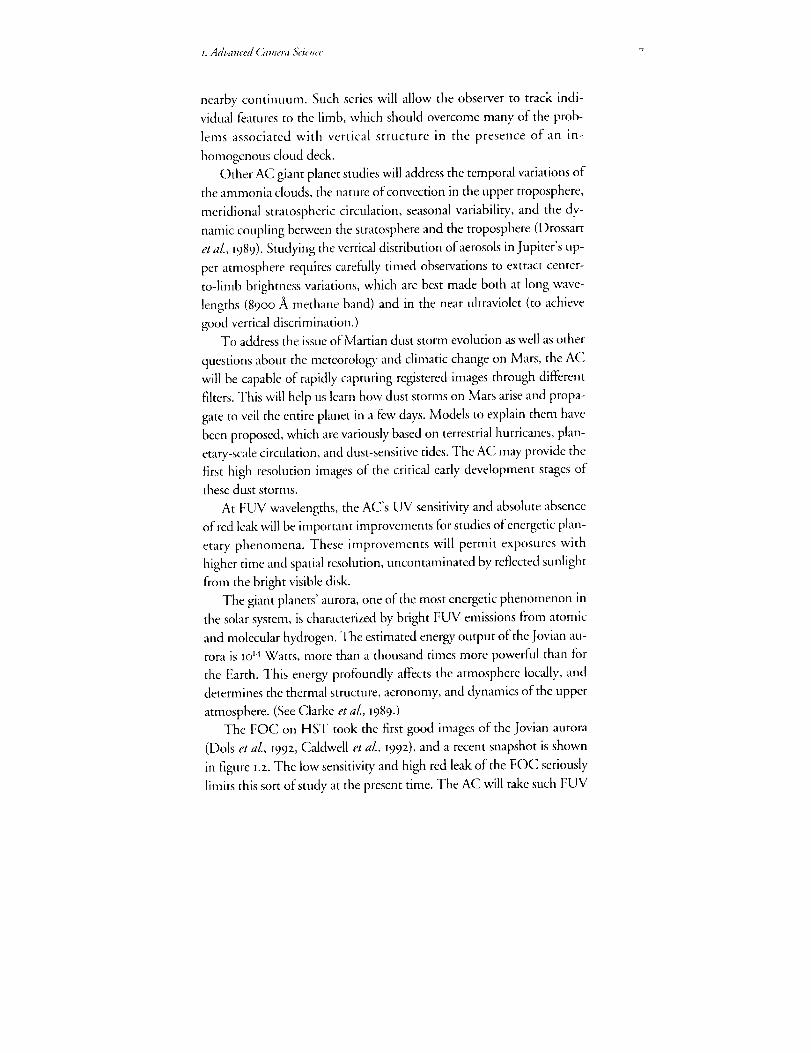
The FO( ] on HST took the first good images of the Jovian aurora
(Dols et al., I992, Caldwell et aL, I992), and a recent snapshot is shown
in figure i.z. The low sensitivity and high red leak of the FOC seriously
limits this sort of study at the present time. The AC will take such FUV

8 FOSI: Frontiers of'Space Imaging
Figure 1.2.FUV image of north
polar region of Jupiter takenby the FOCon Feb. 16, 1993.The image covers a 200/I,
spectral range centered at1530 _, clearly showing thebright ring of the auroracircling the northern hemi-
sphere. This 11"x 11"image hasa spatial resolution ofapproximately 200 km on theplanet. The AC will be able totake such FUVimages withthree times the signal tonoise ratio at one-fifth the
exposure time.
images with 3 times the signal to noise ratio in U5 the exposure time.
Some of the outstanding issues that can be addressed with these capabili-ties are:
• How does the aurora affect thegiantplanets'aeronomy?
• What are the auroralparticles (electrons, protons or heavy ions)
and where do they comej_om?
• What is the connection between the Io plasma torus and the Jovianaurora?
• Is there a connection between the aurora and the Lyman alpha
bulge and dayglow emissions on Jupiter?
• What are the morpholog_ andcause of the Lyman alpha bulge on
Jupiter?
1.3.2 PROTOPLANETARY DISKS
A detailed understanding of the genesis of planets is one of the major
goals of astronomy. Current models of stellar formation and subsequent
evolutionary stages imply the natural occurrence of flattened disks of
material orbiting around young dwarf stars, which would provide the
conditions and opportunity for the accumulation of planets. While the
observational evidence for disks (Bertout, I989; Backman and Paresce,
I99Z) is varied and convincing, the field is still in its infancy and now re-
quires substantial improvements in technical capabilities to advance.
The AC promises to make an important contribution by providing
NUVO images with improved spatial sampling and reduced contami-

t.Advanced Camera &'ience 9
nation by direct starlight. This high dynamic range imaging will be pro-
vided by the high resolution NUVO capability, and will be greatly en-
hanced if the NUVO coronograph is implemented.
Recent studies of large samples ofpre-main sequence stars (PMS) in
the Taurus-Auriga star-forming complex suggest that half the solar-type
stars of age less than 3 million years (Myr) have optically thick disks. At
ages greater than IO Myr, fewer than Io% show signatures of disks. At
these early ages, which are clearly critical for planet building, PMSs also
display energetic stellar winds and bipolar outflows, sometimes with em-
bedded Herbig-Haro objects. High resolution images can be expected to
reveal important clues to the relative roles of accretion and stellar wind
interactions in the evolution of the disks. The gaseous streams should be
evident in emission lines of H, O, Si, and other species, which are ex-
cited by shock heating. Images in the continuum should reveal aspects
of the disk morphology. An appropriate selection of narrow band filters
and interference filters centered on the most important spectral features
as well as the continuum will be a key capability of the AC .The exciting
possibilities of the AC for studies of protoplanetary disks are illustrated
by the recent WFPC images shown in figure 1.3.
PMS protoplanetary disks may be the precursor to optically thin
Figure 1.3. Massive gas disks around PMS stars in M42 as imaged by theWFPC (O'Deli, et al., 1995). A dark accretion disk varies dramatically in itsappearance according to whether it is found close to a hot star (left),which results in the outer disk material being ionized luminous, or at anintermediate (middle), or large distance (right), in which case the disk isseen in silhouette against the bright background of the nebula. Each pixelin this image represents 30 AU. NUVOimages from the AC will provideimproved spatial sampling and reduced contamination by direct starlight,and such images will be further enhanced if the NUVOcoronograph is
implemented.

IO FOSI: Frontiers of Space Imaging
disks like the ones identified by infrared excess around the main se-
quence stars Vega, Fomalhaut, and Beta Pictoris, which are the only
disks thus far confirmed by direct imaging (Backman and Paresce, I992 ).
With ground-based images, the Beta Pictoris disk can be measured in
optical light in to about 4o astronomical units (AU) from the star
(Golimowski, etaL, I993). The zone between io and 5oAU iscritical, for
it is there that a possible planetary system either in formation or already
well formed might reside (Backman, et aL, 199z). Preliminary calcula-
tions for the AC coronographic mode indicate that the scattered light
from the central star will be low enough to permit reliable detection of
the Beta Pictoris disk to within approximately o.7" to I" of the star cor-
responding to 12 to 17 AU. This performance will enable the detailed
study of the colour, radial profile, and possible deviations from symme-
try of the inner regions of the Beta Pictoris system, which could reflect
the presence of planets or planetesimals interacting with the inner diskenvironment.
The AC should also be capable of imaging disks similar to Beta
Pictoris around other IR excess main sequence stars--such as,
Fomalhaut, Vega, and Epsilon Eridani--which has not been possible
from ground-based observatories.
1.3. 3 STELLAR CHROMOSPHERES
Key to the study of the fundamental physics of stars is the imaging of
their surfaces and their interaction with the surrounding circumstellar
environment. Surface imaging of stars revealing the size, structure, place-
ment, and longevity of surface features elucidates the energetics of their
atmospheres, magnetic dynamo and convection theory, and their evolu-
tion. Imaging of winds and extended atmospheres tests and defines the
acceleration mechanisms of mass loss, the structure of extended atmo-
spheres, and the origin of highly energetic processes such as jets from a
surprising number of otherwise mundane systems such as symbiotic
stars. Direct imaging ofsupergiants in the ultraviolet should also reveal
nearby surrounding material indicative of previous mass loss episodes,
and help to define the evolutionary state of these stars. Supergiants offer
one of the most attractive classes of targets for surface imaging because of
their brightness and size.
In the UV, plasmas are sampled at higher temperature than is pos-
sible in the optical region. The chromospheres and coronas of stars are
z. Advanced Camera &:ience n
very extended making them larger targets than their photospheric di-
mensions imply. Recent ultraviolet and X-ray observations of cool stars
in binary systems, for example, suggest that structures extend to several
stellar radii, far in exce_ of the sizes observed on the Sun. Physical inter-
action between these structures and winds of each component would
not be unexpected. The contrast of such structures is high when ob-
served against tbe stellar disk because the photospheric continuum is
weak or absent in the ultraviolet.
Excellent targets for the AC include circumstellar shells such as those
around Gamma Ori. High resolution imaging coupled to ultraviolet
spectroscopy would reveal the place of origin of the wind on the stellar
surface, the morphology of the interaction of the wind with the sur-
rounding medium, the energetics of the wind (fast, slow, hot, cool, etc.),
and molecular formation in extended atmospheres. Two putative com-
panions to the M supergiant Alpha Ori have been reported from speckle
imaging reconstruction techniques: one at a distance ofo.o6", the other
at o.51" (Karovska eta[., I986). Direct imaging with a coronograph
blocking the M supergiant could easily reveal their presence.
Study of targets containing cool stars demands solar blind detectors
to detect the FUV emissions without long wavelength contamination.
Narrow band or interference filters will be required to isolate important
strong stellar and circumstellar emission features such as C lII, C IV,
Hz, Mg II, etc. Search for extended emission around a central star will be
carried out, in many cases, with the AC coronographic mode used to oc-
cult the bright central object.
The nova is another important class of object that now can be stud-
ied in greater detail. High resolution UV and optical imaging is required
to study the initial development of instabilities in the shell before sub-
stantial mixing occurs with the interstellar medium. For Nova Cyg I99z,
for example, an optical interferometric angular diameter measurement
in the first three weeks after outburst gave o.o33" at Balmer alpha, corre-
sponding to material moving at about 50o km/sec, for a distance of
I kpc. This implies that the o.os" to o.I" imaging capability of the AC
will permit direct imaging of the early shell within the first year of a
bright, nearby ejection. Ultraviolet narrow band imaging measures the
different depths in the shell by using specific permitted and
intercombination transitions and would permit measurement of the
structure of the highest velocity material. The direct imaging of the shell
I2 FOSI: Frontiers of Space Imaging
is a key to the interpretation of ultraviolet and optical spectra, providing
explicit information about departures from spherical symmetry.
Comparison between UV and radio imaging is an especially impor-
tant aim for this part of the study. For recurrent novae and symbiotics,
imaging of jets and circumstellar material originating from the interac-
tion between different components of binary systems, including red gi-
ants (as in T CrB and RS Oph), will be a important objective of the AC.
Direct spatial resolution of the binary system and its accretion disk in
nearby objects is a distinct possibility, since they are expected to have
typical sizes of order o.o4" to o.o6" at 25o pc.
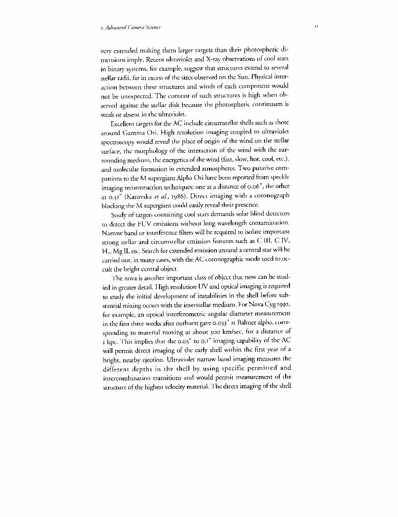
Figure _.4 shows an FOC image of R Aqr, which is an example of
Figure 1.4. Direct image in the emission line C Ill at 1909/_ of the jet
emanating from R Aqr, a Mira variable that is a component of an activesymbiotic binary system. Because the very bright Mira is cool and,
therefore, its ultraviolet continuum weak, the FUV emissions from the jetcan beisolated easilyall the waydownto severalAU from the Mira. Theinsert in this figure showsthat the putative hot, compact secondary (H)may bejust resolvedfrom the Mira (M). North is up,east is to the left.Each pi×elin this imagecorresponds to 0.022" onthe sky.
stellar imaging of this type (Paresce and Wilkins, I992). The AC, with its
superior resolution and sensitivity, should establish the nature of such
interesting objects and allow studies of their evolution, since significant
changes are observed to occur on time scales of less than a year. The for-
I.Advanced Camera &'ience _3
tuitous fact that R Aqr is close by (-zoo pc) suggests the possibility of
imaging in similar detail a large number of other more distant active stel-
lar systems. This should clarify the physical processes that are common
to all post MS systems especially those in which extended atmospheres
interact strongly with the circumstellar environment.
1.3. 4 STELLAR POPULATIONS
An understanding of the mechanisms of star formation, including
the parameters that govern the process, is a critical problem in both stel-
lar astrophysics and cosmology. A central issue is the determination of
the initial mass function (IMF), which is the function describing the
production rate versus stellar mass. The slope, shape and mass range of
the IMF influence a wide range of processes and problems, including the
early chemical history of the Galaxy, the evolution and predicted prop-
erties of high redshift galaxies, the population of stellar remnants in the
Galaxy, and the missing mass problem.
Studies of resolved stellar populations in nearby galaxies have taught
us a great deal about stellar evolution, including some of the parameters
of star formation in particular systems: IMFs, chemical abundances, and
age distributions. However, ground-based studies are severely confu-
sion-limited and are impeded by restricted wavelength coverage. Only
in the nearest systems, such as the Magellanic Clouds, have we been able
to construct colour-magnitude diagrams down to I to z magnitudes be-
low the main-sequence turnoffofthe old populations. Many fundamen-
tal questions remain unanswered: How variable is the IMF over the
Universe? How does it depend on the mean metallicity of the gas fromwhich stars are formed? Is there bimodal star formation in normal and/
or starburst galaxies?
The ultraviolet holds great potential for resolving these and other
vexing problems concerning the age and metalticity distributions of stel-
lar populations, including the problem of the ultraviolet upturn in old
stellar populations. A single solar-blind, wide-field ultraviolet exposure
with the AC will yield a complete sample of hot stars in a nearby galaxy.
Such an exposure would include specimens exhibiting rapid and there-
fore rare phases of post-giant-branch evolution, the status of which ob-
jects is not yet fully understood.
In very crowded regions, ultraviolet images taken with the AC will
isolate hot objects from the often dominant background of cool stars

I4 FOSI: Frontiers of Space Imaging
Figure 1.5. Woif-Rayet stars in a large extragalactic starburst region,imaged in B-band, of the giant HII region NGC 604 in M33 (Drissen et at.,
1993). The image on the left was obtained using the 3.6 m Canada-France-Hawaii Telescope (seeing = 0.8"). The image on the right was takenwith the HST WFPC in PC mode. All previously claimed 'superluminous'Wolf-Rayet stars (as inferred from ground-based images) are now foundto be tight (diameter < 5 pc) aggregates containing one (or sometimesmore) normal W-R star on HST images. Atso, such HST images have
allowed a preliminary determination of the initial mass function for starsin the 15 to 7Q solar masses range. With the AC, such stellar populationstudies will be powerfully extended.
(e.g., in the crowded cores of globular clusters in the Magellanic Clouds
and in the nuclei of nearby galaxies.) Ultraviolet images will also contain
much information on interstellar dust and be aided by significantly
darker sky background. In short, the AC with a wide separation of pass-
bands from 12oo to Io,ooo fit will separate factors of age, metallicity, and
reddening much more effectively than previously possible.
Besides increased ultraviolet sensitivity, both high-resolution and
wide-field capabilities of the AC will be important for stellar-population
studies. To learn the star formation histories in Local Group galaxies, in-
cluding the dwarf spheroidals around the Milky Way and M3_, the AC
will obtain multi-colour images (including the ultraviolet) that cover
relatively wide areas (several arcminutes). Large-area coverage will also be
an advantage for studying such objects as the blue So galaxy NGC 5Io2,
in which the AC can establish_irectly by star counts--the fraction of
stars formed in a recent starburst, rather than having to rely upon inter-
preting the integrated spectrum via the cruder technique of population
synthesis. In other studies, the highest possible resolution over smaller

l.Advanced Camera N'iencc 15
areas (tens of arcseconds) will be necessary to diminish problems due to
crowding. In this way, for example, high-resolution AC images of
globular clusters in M31 and other Local Group galmxies may help settle
the question of the age spread in these cluster systems.
1.3.6 ACTIVE GALACTIC NUCLEI
Quasars and active galactic nuclei (AGN) are among the most im-
portant targets for the HST for at least two reasons. First, they include
the most energetic objects known, and are believed to be powered by the
gravitational energy released as matter is accreted onto a rotating black
hole. They are therefore fundamental testbeds for studying high-enerDr
astrophysical processes. Secondly, because of their enormous luminosi-
ties, the), can be studied out to distances corresponding to the epoch
when the Universe was only about m% of its present age. Their attrac-
tiveness a.s probes of the early Universe is reinforced because they fre-
quently emit luminous emission lines, from the ultraviolet to the infra-
red, w_ich _lows them to be recognized and their distances determined.
Among basic physical questions of interest are:
• Are AGN really pouered by ffravitatio,ml energy released by the accre-
tion of material onto a black hole?
• What # the relative effbct of orientation, environment (hostga_xy and/
or cluster), and hDtory on determining the obserwational properties of
AGN?
• How # nuclear activity related to the formation and evolution of"
galaxies?
]'here are several spatially-extended components of active galaxies
that can be studied in the optical and the FUV. These include light from
stars of various ages, non-thermal radiation from synchrotron jets, scat-
tered emissions, and emission lines from ionized gas. Observations over
a range of wavelengths from the red to the far ultraviolet through broad
and narrowband filters are essential to separate these various compo-
nents. Imaging polarimetry will provide an important discriminant in
the case of synchrotron emission and scattered light.
Several capabilities of the AC will 'allow important advances in the
study of'quasars and AGN. These include (I) high dynamic range and/
or coronographic observations of the nuclear environments ofAGN, (z)
UV broad-band imaging of AGN hosts, (3) wide-field narrow-band im-
aging of nearby, active galaxies, and (4) wide-field imaging of host envi-

r6 FOSI: Frontiers of Space Imaging
rons (e.g. host clusters) surrounding AGN.
Detailed imaging of the central i kpc of AGN is crucial for studying
the interaction of AGN with their host galaxies. By imaging in several
bands in the optical and ultraviolet, morphological information on the
different components of the stellar population can be obtained and re-
lated to that of the ionized gas close to the AGN. Do younger stars tend
to be formed closer to the AGN? ls there morphological evidence indi-
cating the presence of massive black holes (cusps, disks etc.)? Because
such observations must be carried out near a dominant central point
source, they place stringent requirements on dynamic range and spatial
resolution. The AC's coronograph, non-blooming charge coupled de-
vices (CCD), high spatial resolution, and enhanced FUV imaging capa-
bilities should revolutionize such studies. In particular, comparison of
the optical imaging with radio interferometfic imaging carried out with
similar resolution will provide unique diagnostics of astrophysical pro-
cesses involving jets and their interaction with the nuclear regions
(Miley, _98I).
To study the evolution of the host galaxies, it is vital to image distant
and nearby galaxies at similar rest wavelengths. FUV imaging of nearby
active galaxies is therefore complementary to optical imaging of high-
redshift AGN hosts. Radio galaxies are of particular interest for such
studies. Distant radio galaxies tend to have their optical continuum
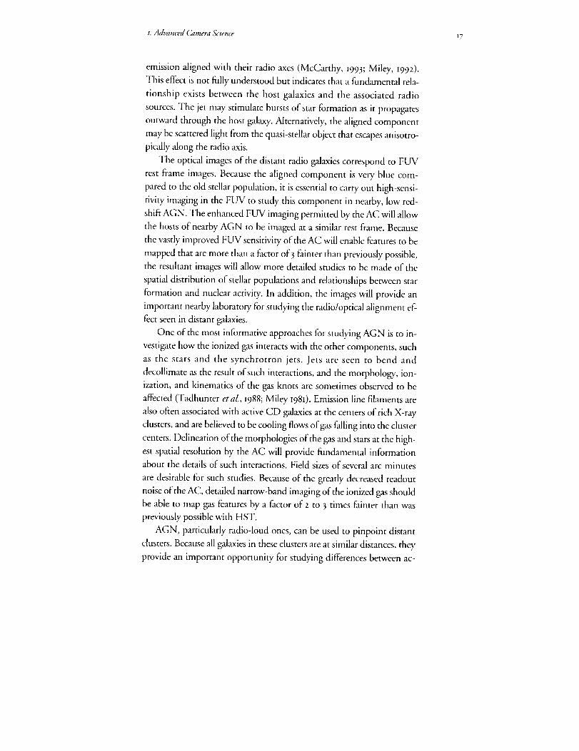
Figure 1.6. FUV image taken with the HST FOC of the long plasma jetemanating from the active nucleus of the giant elliptical galaxy M87
(Macchetto 1992). The jet's high polarization and similar appearance atradio wavelengthsindicate non-thermalsynchrotron emission.TheimprovedFUVcapabilities of the ACwill allowthe mappingof AGNfeatures a factor of three times, and at higherresolution than previouslyachieved.
I. Advanced Camera &'ience 17
emission aligned with their radio axes (McCarthy, 1993; Miley, 1992 ).
This effect is not fully understood but indicates that a fundamental rela-
tionship exists between the host galaxies and the associated radio
sources. The jet may stimulate bursts of star formation as it propagates
outward through the host galaxy. Alternatively, the aligned component
may be scattered light from the quasi-stellar object that escapes anisotro-
pically along the radio axis.
The optical images of the distant radio galaxies correspond to FUV
rest frame images. Because the aligned component is very blue com-
pared to the old stellar population, it is essential to carry out high-sensi-
tivity imaging in the FUV to study this component in nearby, low red-
shift AGN. The enhanced Fl_ imaging permitted by the AC will allow
the hosts of nearby AGN to be imaged at a similar rest frame. Because
the vastly improved FUV sensitivity of the AC will enable features to be
mapped that are more than a factor of 3 fainter than previously possible,
the resultant images will allow more detailed studies to be made of the
spatial distribution of stellar populations and relationships between star
formation and nuclear activity. In addition, the images will provide an
important nearby laboratory for studying the radio/optical alignment ef-
fect seen in distant galaxies.
One of the most informative approaches for studying AGN is to in-
vestigate how the ionized gas interacts with the other components, such
as the stars and the synchrotron jets. Jets are seen to bend and
decollimate as the result of such interactions, and the morphology, ion-
ization, and kinematics of the gas knots are sometimes observed to be
affected (Tadhunter et al., I988; Miley 198I ). Emission line filaments are
also often associated with active CD galaxies at the centers of rich X-ray
clusters, and are believed to be cooling flows of gas falling into the cluster
centers. Delineation of the morphologies of the gas and stars at the high-
est spatial resolution by the AC will provide fundamental information
about the details of such interactions. Field sizes of several arc minutes
are desirable for such studies. Because of the greatly decreased readout
noise of the AC, detailed narrow-band imaging of the ionized gas should
be able to map gas features by a factor of 2 to 3 times fainter than was
previously possible with HST.
AGN, particularly radio-loud ones, can be used to pinpoint distant
clusters. Because all galaxies in these clusters are at similar distances, they
provide an important opportunity for studying differences between ac-

18 FOSI: Frontiers of Space lmaging
tive and passive galaxies and the evolution of nuclear activity. The simul-
taneous ability to provide high spatial resolution and wide field give the
AC a clear advantage in carrying out such programs.
AGN research of the types mentioned here will be especially impor-
tant drivers for the design of the coronograph, the requirements of the
polarizers, and the specification of the filters.
1.3. 7 GALAXIES AND GALAXY CLUSTERS
One of contemporary astronomy's outstanding issues is understand-
ing how galaxies evolve and when this evolution takes place. While we
have been very successful ill characterizing the present state of nearby gal-
axies, it has proved to be quite difficult to unambiguously define their evo-
lutionary history and time scales. When galaxies first formed they would
have been quite unlike those of today. Their sizes, shapes, and internal
dynamics, as well as the age and abundance characteristics of their stellar
and gaseous constituents, have changed since fbrmation, reflecting the physi-
cal processes that have acted upon them over the last -IO billion years (Gyr).
Galaxies also bear the imprint of their environment; galaxies in denser re-
gions systematically differ from those in less dense or 'field' regions. To
establish what has happened we need to analyze the properties of distant
galaxies and the characteristics of their environment as a function of'lookback'
time. The AC will be eminently suited for this task.
Studies of galaxy evolution also have ramifications for cosmology.
Firstly, the observations carried out to characterize galaxy properties as a
function of redshift typically also provide data on the spatial distribution
of galaxies and on the evolution of their clustering properties with red-
shift. Such results provide a window on the scale and amplitude of the
perturbations that seeded galaxies in the early universe. Secondly, a vari-
ety of key tests for deriving cosmological parameters (e.g., qo and A from
the geometry of the Universe) require that we have galaxy samples for
which the evolutionary changes with redshift have been quantified. Ad-
equate samples do not yet exist with demonstrable, quantified con-
straints on evolutionary change.
Structures in galaxies (e.g., spiral arms, disk and bulge sizes), which
provide a means of establishing the galaxy type and its dynamical state,
typically have length scales less than about I kpc (and sometimes
<< I kpc). Since one arcsecond corresponds to roughly 7 kpc at a redshift
z = o.5 (for qo = o.5 and Ho = 5o), imaging with resolutions of better

*.Advanced Camera Science 19
than o.l" are essential. As illustrated in figure 1.7, WFPC is providing a
glimpse of what the required capability will accomplish: images of dis-
tant clusters and field galaxies from Dressier et al. (I993), Couch et al.
(i993), and Griffiths et al. (I99 z) provide truly unique data from which
we can determine morphological types, determine length scales, and
characterize the environment of galaxies.
Qualitative analyses, which compare the data with the large body of
morphologically defined types of nearby galaxies, are superficial but im-
mediately productive. The reason is that the morphological appearance
reflects certain physical and kinematical properties of the galaxy. The
quantitative measurements extend the characterization of distant galax-
Figure 1.7. One WFC frame in R-band of the distant cluster CL 0939+4713at z=0.40. Such a detailed view over a large field of a distant cluster is a
unique capability of HST. The outlined area at the top, west of the QSO,
shows a concentration of faint, compact galaxies that may be at the
quasar redshift (z=2.055), and so could be the highest redshift clusterknown.
The insert shows the gravitationally lensed galaxy in the cluster AC 114
at z=0.3 from a V-band WFC image. The remarkable symmetry in this faint
image exemplifies the power of HST for studies of distant galaxies.

20 FOSI: Frontiers of Space Imaging
ies and directly rdate them to their present-day counterparts.
HST AC images will allow the identification of the regions in which
star formation (if any) is taking place, characterize the presence of spiral
arms, bars, and other structural features, highlight the existence of inter-
actions and mergers, identify whether AGN-like compact cores exist,
and quantify the distribution of dust, gas and different stellar popula-
tions. Correlation of these properties with other data such as radio, X-
ray and infrared observations will add further insight into the physics
that governs galaxy evolution. HST with the AC will provide images of
distant galaxies that will show more detail, irrespective of their redshifi,
than those that are typically obtained with ground-based telescopes ofthe Coma cluster.
The case for the wide-field, high resolution capability of the AC is
enhanced by consideration of the synergism with multi-object spectro-
scopic observations on large ground-based telescopes. Spectroscopic ob-
servations alone are not sufficient for a comprehensive study of distant
galaxies, but they do provide unique data that greatly strengthens the
value of imaging data from HST. Such images allow us to relate the ob-
jects being studied directly to their present day counter-parts, while the
spectroscopic results provide an estimate of their physical state. The im-
portance of this complementary role cannot be stressed too highly. Dis-
tant galaxies are incredibly difficult objects to study and relate to well-
understood, nearby systems.
By the late i99os and into the next century, huge investments will
have been made in the VLT at ESO, at Keck, and most likely in the
Magellan, Columbus, and Gemini telescopes. These ground-based ob-
servatories will surely conduct major programs on distant galaxies using
multi-object spectrographs. The FOVs covered by these spectroscopic
systems and the HST AC are comparable, as are the magnitude limits
for high resolution imaging of galaxies and multi-object spectroscopy
(B _ 24 to 25"magnitude). The synergism and scientific returns that will
result from concurrent use of these 8 to IO m class telescopes for multi-
object spectroscopy with high-resolution, wide-field, NUVO imagesfrom the AC on HST cannot be overstated.
It is crucial that an imager such as the HST AC be available when the
8 to io m telescopes with their complementary multi-object spectro-
graphs are being used to carry out deep galaxy surveys. Yet, because of
lifetime considerations, the WFPC II may not be available, and thus no
s.Adl,a,ced Camera &:ience 21
relevant imaging capability is assured around the year 2000 without the
AC. While WFPC II, if it is available, will clearly provide substantially
improved imaging capability for distant galaxies over that of WFPC,
and could provide the imaging data for the complementary spectro-
scopic programs, it is substantially inferior to the baseline AC. It will
have a figure of merit that is < io% of that of the AC. Its areal coverage
will be < 5o% of the baseline AC, its quantum efficiency < 5o%, and it
will have poorer resolution by at least a factor of 2 (and probably worse
since the potential gains with sub-pixel stepping will be less because of its
poorer spatial scale: o.i" in WFC mode versus o.o5" in the AC wide-
field mode.) The gains to be made with the AC over WFPC II for dis-
tant galaxies are comparable to those of WFPC II over the aberrated im-
ages of WFPC.
It is clear that a wide-field, high-resolution AC with NUVO spectral
coverage will provide a uniquely powerful capability for obtaining the
large samples and detailed images of galaxies and clusters of galaxies that
are needed for tackling one of the most outstanding and interesting
problems of astronomy.
1.3,8 THE COSMOLOGICAL MODEL
The determination of the global value of the Hubble constant is the
most important question in observational cosmology today. A close sec-
ond is the determination of the mean mass density of the Universe,
which means its total dark matter content. Despite over 6o years of work
on the fundamental cosmological model and the substantial improve-
ment in our ability to detect and observe galaxies and other cosmological
tracers, there remains considerable uncertainty in the parameters of the
currently accepted cosmological model, the Friedmann-Lemaitre model
(also known as 'the hot Big Bang'). In particular, despite recent suc-
cesses, including the improved calibration of the luminosities of type Ia
Supernovae (SN) from HST observations of Cepheids in IC418z
(Sandage et aL, x992), a new measurement of the distance to the LMC
(Panagia et al., 199I), and improved ultraviolet spectroscopy of type II
SN (Kirshner eta/., I993), the value of the Hubble Constant (Ho) is still
uncertain by more than 5o%. This is due to the lack of agreement be-
tween several powerful methods (Huchra, I992; Jacoby et al., 1992; Van
den Bergh, 1992).
An accurate and unambiguous determination of Ho is essential. The

22 FOSI:FrontiersofSpace Imaging
Figure 1.8. A Cepheid in the spiral galaxy/C 4182 shown in two imagestaken five days apart by the WFPC in the WF mode. The superior imagingcapabilities of the AC will permit detection of Cepheids at furtherdistances than currently possiHe, and yield more data to narrow downthe value of the Hubble constant.
high values for Ho preferred by most observers are in serious conflict
with the combination of the age determinations for globular clusters
(and the oldest stars in the Galaxy) and with the requirement of a flat
Universe from inflationary cosmologies.
Without an accurate calibration for Ho, we cannot even determine
the fundamental parameters for extragalactic objects, much less test the
cosmological model. An ambitious Key Project was planned to provide
this calibration via the measurement of accurate Cepheid scale distances
to a large number of galaxies using HST. This program was put on hold
by spherical aberration. While WFPC II will provide some capability for
proceeding with the program, the AC will provide substantially improved
capability, including a significantly larger and better sampled FOV. Cep-
heids in Virgo cluster galaxies would have been marginally detectable with
WFPC unhamperedby spherical aberration. TheAC, with 2x better sam-
piing, the use ofsubstepping, improved throughput, image deconvolu-
tion techniques, and a 3x larger FOV, will reach Cepheids beyond Virgo,
and provide much improved accuracy in nearer galaxies.
In addition, several other key distance measuring techniques depend
on the ability to survey galaxies with high spatial resolution, high send-
tivity, and a wide FOV. These include measurement of brightest stars,
the globular cluster luminosity function, the planetary nebulae luminos-
z.Advanced (5zmeraScience z3
ity function, and even the fluctuation technique of Tonry and Schneider
0988) (because the amplitude of fluctuations in an unresolved stellar
population depends inversely on the area of the spatial resolution ele-
ments). While these techniques generally depend on the Cepheid cali-
bration, and are somewhat less accurate, with the AC they can be ex-
tended to much larger distances.
Currently, density determinations based on dynamical studies of in-
dividual galaxies or bound galaxy systems, such as clusters and groups,
indicate that the mass density Fails to meet the closure density by a factor
of 3 to 5 (Trimble, i988 ). Attempts to match large scale galaxy velocity
fields and the cosmic microwave background dipole velocity with the
local large scale galaxy density field, however, appear to be giving values
of_;2 near unity (Strauss eta/., I992).
While ground-based surveys of galaxy velocities will substantially im-
prove our knowledge of the density field over the next decade, the factor
limiting the errors in flow determinations is our ability to measure accu-
rate relative distances for large numbers of galaxies. Global techniques,
such as Tully-Fisher or fundamental plane relations, provide distances to
individual galaxies that are at best zo% accurate, and can only be used
on a fraction of all galaxies. Furthermore, they suffer from selection bi-
ases, such as the Malmquist effect (Huchra, 1992 ). The substanti'al im-
provement in distance-measuring accuracy needed to map the velocity
field to IO,OOO km/s, which would provide an unambiguous determina-
tion of_ on large scales, can be provided only by the AC on HST.
21.O i P 4_*_; _ , V, I:
•".. ,..... ,.'._;i;' iL;' , ; •
°°°l _°°¢
23,;' F' :32 _ , '_ :, bl.;{_3 ,
25 ,)
24.(! ' f 4Z, _ ,'v> 2_9_F, -
%* "i;1÷f +!!!!+++
0 0 C' _-; 1 () I _ 2, :'
Phase
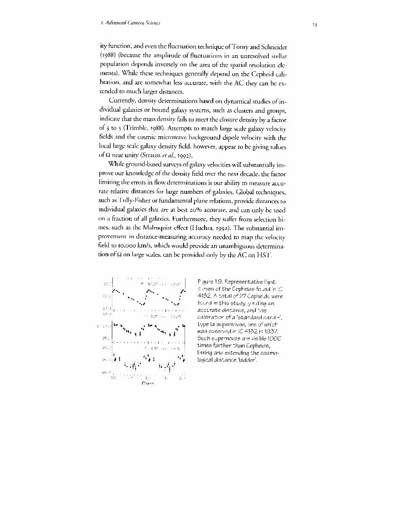
Figure 1.9. Representative lightcurves of the Cepheids found in IC4182. A total of 27 Cepheids werefound in this study, yielding anaccurate distance, and thecalibration of a 'standard candle',
type la supernovae, one of whichwas observed in IC4182 in 1937.
Such supernovae are visible 1QO0
times farther than Cepheids,linking and extending the cosmo-logical distance 'ladder'.
24 FOSI: Frontiers of Space Imaging
Lastly, the determination ofqo independent of rio and _ has eluded
astronomers for decades. Chief among the problems associated with its
determination is the effect discussed in the earlier section on galaxies and
galaxy clusters--the evolution of the standard candles and standard
measuring rods that might be used to measure the curvature of the uni-
verse. There is at least one route to qo which depends on a standard
candle for which the evolution expected is small or nonexistent. The
mechanism for the detonation of SN Ia is probably dependent only on
the accretion processes onto white dwarfs in binary systems. SN la can
be seen to great distances (redshifts) and can be discovered by large
ground-based telescopes. However, to unambiguously classify the SN
and to follow its light curve long enough to measure the expected time
delay (I + z) requires imaging with the superb resolution of HST. Only
this capability can extract the SN from the light of the surrounding gal-
axy. Galaxy clusters are now being observed at redshifts near unity. A
well observed sample of a few dozen supernovae la in these clusters will
provide a galaxy and cluster evolution independent estimate ofqo.
Similarly, the use of gravitational lenses to study cosmological pa-
rameters is just coming into its own (Schneider, Ehlers and Falco, i99z).
The monitoring of existing lensed quasars requires excellent and stable
imaging performance, and new lenses discovered by HST perforce will
require HST follow-up observations, especially in the blue and ultravio-
let, where quasar variations are largest. The improved sensitivity and
spatial resolution of the AC are crucial not only for finding new lenses
but also for systematic, high precision monitoring of these objects over
long periods of time and for accurate determination of the mass models
for the lens systems themselves (Bernstein et al., I993).
ACKNOWLEDGEMENTS
John Huchra was the lead author of chapter i. Contributions were made byReta Beebe, Howard Bond, Andrea Dupree, Heidi Hammel, John
Hoessel, Garth Illingworth, Tod Lauer, Edwin Loh, Duccio Macchetto,
Bruce Margon, John Mathis, Melissa McGrath, George Miley, David
Monet, Jeremy Mould, Susan Neff, Francesco Paresce, John Raymond,Francois Schweizer, Steven Shore, Man Stern, and Donald York.
REFERENCES
Backman, D.E., Gillett, F.C., and Witteborn, F.C. 1992. Infrared observa-
tions and thermal models of the Beta Pictoris disk. Ap.J., 385, 67o-679.
1. AdvaJ_ced (.}lmera Science z_
Backman, D.E., and Paresce, F. Main sequence stars with circumstellar solid
material: the Vega phenomenon. In ProtostarsandPlanetslIl, eds. E.H.
Le W, J.1. Lunine, and M.S. Matthews (Tucson: Univ. of Arizona Press,
t99z) Iz53.
Beebe, R.F., Orton, G.S., and West, R.A. i989. Time-variable nature of'the
Jovian cloud properties and thermal structure: an observational per-
spective. In Time Variable Phenomena in the Jovian System, eds. M.
Belton, R. West, and J. Rahe. NASA SP-494, 245-z88.
Bernstein, G., Tyson, J.A., and Kochanek, C. 1993. A large arc in the
gravitational lens system o957+56t. AJ, 1o 5, 816-83o.
Bertout, C. 1989. T Tauri stars: wild as dust. AnnRevA&Ap, z 7, 39-395.
Caldwell, J., Turgeon, B., and Hua, X.-M. I99z. Hubble Space Telescope
imaging of the north polar aurora on Jupiter. &ience, 2,57, I512-I5I 5
Clarke, J., Caldwell, J., Skinner, T., and Yelle, R. 1989. The aurora and
airglow of Jupiter. In Time Variable Phenomena in the Jovian System,
eds. M. Belton, R. West, and J. Rahe. NASA SP-494, 2H-22o.
Couch, W.J., Ellis, R.S., Sharpies, R.M., and Small, I.R. I993 In Texas/
PASCOS Symposium, Berkeley, in press.
Dols, V., Gdrard, J.C., Paresce, F., Prangd, R., and Vidal-Madjar, A. 1992-.
Ultraviolet imaging of the Jovian aurora with the Hubble Space
Telescope. Geophys.Res.Lett., 19, 18o3q8o6.
Dressier, A., Oemler, A. Jr., Gunn, J., and Butcher, H. 1993. A cluster of
nascent galaxies at z=z? ApJL, 404, L45-L49.
Drissen, L., Moffat, A.F.J., Shara, M.M. 1993. Hubble Space Telescope
Planetary Camera view of giant H II regions: the Wolf-Rayet content
of NGC 595 and NGC 6o 4 in M33. A.J., IO_, t4oo-m.
Drossart, P., Courtin, R., Atreya, S., and Tokunaga, A. I9g 9. Variations in the
Jovian atmospheric composition and chemistry. In Time Variable
Phenomena in the Jovian System, eds. M. Belton, R. West, and J. Rahe.
NASA SP-494, 344-36z.
Ellis, R. etal. t993- MNRAS, in press.
Golimowski, D., Durrance, S., and Clampin, M. _993- Coronographic
imaging of the Beta Pictoris circumstellar disk: evidence of changing
disk structure within mo AU. ApJL., in press.
Griffiths, R., Ramatunga, K., Doxsey, R.E., Ellis, R. etal. The Hubble Space
Telescope medium deep survey: status report and first results. In ST-
ECF/STScI Workshop: Science with the Hubble Space Telescope, Proceed-
ings, eds. P. Benvenuti and E. Schreier (Munich: European Southern
Observatory, I992) 13-zo.
Huchra, J. I992. The Hubble Constant. Science, z56, 3zi-32. 5.
26 FOS[: Frontiers of Space Imaging
Jacoby, G., Branch, D., Ciardullo, R., Davies, R., etal. I992. A critical review
of selected techniques for measuring extragalactic distances. PASP, lO4,
599-662.
Karovska, M., Nisenson, P., and Noyes, R. 1986. On theAlpha Orionis triple
system. ApJ, 3o8, 26o-269.
Macchetto, F.D. I992. HST observations of Jets. In ST-ECF/STScI Work-
shop: Science with the Hubble Space Telescope, Proceedings, eds. P.
Benvenuti and E. Schreicr (Munich: European Southern Observatory,
1992) 73-81.
McCarthy, P. 1993. High redshift radio galaxies. AnnRevA&Ap, in press.
Miley, G.K. Distant galaxies with the Hubble Space Telescope. In ST-ECF/
STScI Workshop: Science with the Hubble Space Telescope, Proceedings,
eds. P. Benvenuti and E. Schreier (Munich: European Southern Obser-
vatory, I992) t-II.
Miley, G.K. [98I. Jets and the Space Telescope--an introduction. Proc.
ESO/ESA workshop "optical jets in galaxies." ESA Publications, 22.
O'Dell, C.R., Wen, Z., and Hu, X. 1993. Discovery of new objects in the
Orion Nebula on HST images: shocks, compact sources, and proto-
planetary disks. Ap.J., in press.
Panagia, N., Gilnlozzi, R., Machetto, F., Adorf, H.-M., and Kirshner, R.P.
I99I. Properties of the SN I987A circumstellar ring and the distance to
the Large Magellenic Cloud. ApJL, 380, L23-L26.
Paresce, F., and Wilkins, T. The core and jet of the symbiotic R Aquarii
resolved in the UV with HST. In ST-ECF/STScI Workshop: Science with
the Hubble Space Telescope, Proceedings, eds. P. Benvenuti and E.
Schreier (Munich: European Southern Observatory, I992) 329-33 [.
Sandage, A., Saha, A., Tammann, G.A., Panagia, Nino, and Macchetto, D.
1992. The Cepheid distance to IC 4182: calibration ofM (max) for SN
la 1937C and the value of H. ApJL, 4Ol, L7-L[o.
Schneider, P., Ehlers,J., and Falco, E., GravitationalLenses(Berlin: Springer-
Verlag, t992).
Strauss, M., Yahil, A., Davis, M., Huchra,J., Fisher, K. _992. A redshift survey
of IRASgalaxies v. the acceleration on the local group. ApJ, 397, 395-419 •
Tadhunter, C.N., Fosbury, R.A.E., di Serego Alighieri, S., Bland, J., Danziger,
I.J., Goss, W.M., McAdam, B. and Snijders, M.A.J. [988. Very ex-
tended ionized gas in radio galaxies - 1V PKS 2152-69. MNRAS, 235,
403-423.
Tonry, J. and Schneider, D. I988. A new technique for measuring extragalac-
tic distances. AJ, 96, 8o7-815.
Trimble, V. _988. Existence and nature of dark matter in the Universe. In
AnnRevA&Ap, 25, 425-472.
van den Bergh, S. t992. The Hubble parameter. PASP, Io4, 861-883.

27
2. Instrument Status
What scientific imm_ments will be operational on Hubble 3paceTelescope (HST) in _999? By mid-I999 there will have been nvo
servMng missions and several insowments will have been rep_leed.
We have reviewed, the current instrumentation and future plansboth to assure that an Adwmced Camera (A 0 is needed in I999_
rather than some other ty])e of instrument--and" to understand
how the AC could best extend, or complement previous hnaging ol-
])abilities.
We co,_rm that an 3C operating between fooo and m, ooo 14 is
required, to assure an eadequate imaging capabili O, on 1-15"Tat t_e
turn of the century.
rom its conception, instrument replacement has been a fhnda-mental aspect of" the design and program plan of the HubbleSpace Telescope (HST). Experience with ground-based observa-
tories shows telescopes to have longer useful lives than instruments,
which demand frequent repairs and can become outdated by advances
in technology. HST's instrument replacement philosophy assures the
continuity of basic observing capabilities while enabling the introduc-
tion of different or more powerful instruments as they become available.
This approach promises to accrue fill scientific benefit from the signifi-
cant capital investment in the HST spacecraft and telescope optics,
which are the stable foundation of an observatory with a usefid life of'at
least 15years.
2..I HST SCIENTIFIC iNSTRUMENTS IN I993
Currently, in I993, HST science instrumentation consists of two
cameras, the Wide Field Planetary Camera (WFPC) and the Faint Ob-
ject Camera (FOC), two spectrographs, the Goddard High Resolution
Spectrograph (GHRS) and the Faint Object Spectrograph (FOS), and
the High Speed Photometcr (HSP). WFPC occupies a radial bay, while
the other instruments occupy the four axi_ bays. (See chapter 6.) Fine

28 FOSI:Frontiersof Space Imaging
Guidance Sensors (FGS) in the other radial bays are used for telescope
guiding and are also available for astrometric studies. (See chapter 4-)
Spherical aberration of the H ST primary mirror has affected the per-
formance of all current scientific instruments (Sis). The aberration has
caused some but not all astronomical imaging programs to be delayed
until after the I993 servicing mission, the primary objective of which is
to restore image quality. The science program of HST in the first three
years has tended to emphasize spectroscopy over imaging. To mitigate
the effects of spherical aberration, many scientists routinely use image
deconvolution techniques.
Hardware problems have developed in all the instruments, which af-
fects their scientific use. Several problems are serious. The WFPC has no
useful response below 3ooo A because of internal contamination and is
being used solely as an optical camera. The FOC f/48 imaging mode has
developed an intermittent operating problem in its high voltage circuits.
Early on in the mission, GHRS suffered an electronics failure, with the
main loss being the echelle mode in the far ultraviolet (from 125o to 18OO A),
this loss may be recovered during the 1993 servicing mission. FOS suffers
from a loss in sensitivity in a narrow wavelength region centered near I95o -'_.
Other, but less serious, instrumental problems have appeared, which can
be corrected by additional calibrations or new observing procedures.
2.2 EXPECTED STATUS IN I999
To understand the niche and role of the AC, it is necessary to con-
struct an understanding of the status of liST and its instrumentation in
I999, based on developments underway and servicing missions planned.
On the first HST servicing mission in I993, astronauts will replace
the WTPC with an improved version 0WFPC II), which will correct in-
ternally for the spherical aberration of the primary mirror. They will also
install the Corrective Optics Space Telescope Axial Replacement
(COSTAR), which will deploy correction optics in front of the FOS,
GHRS and FOC. Also, the solar arrays, gyro packages and other failed
or degraded units will be replaced.
The second servicing mission, planned for I997, will install two sec-
ond-generation instruments in HST--the Space Telescope Imaging
Spectrograph (STIS) and the Near Infrared Camera (NICMOS)--and
replace other spacecraft hardware units that may have failed.
2. ]nstrument Stctttls 29
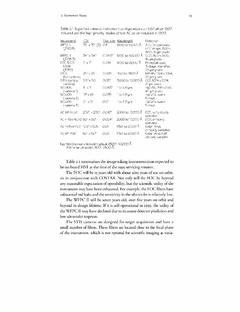
Table 2.1. Expected camera instrument configurations on HST after 1997.
included are the high-priority modes of the AC to be installed in 1999.
Instrument FOV Pi×el size Wavelength Detector
WPFC I] 75" × 75" (3) 0.1" 1200 to 10,000 _ 3 CCDs combined
(f/12.9) in 'L' shape. 800 ×
800, 15 tam pixeisWFPC II 34" × 34" 0.046" 1200 to 10,000/_ CCD, 800 × 800,
(f/28,3) 15urn pi×elsFOC & CO- 7"x 7': 0.014" 1200 to 6000/_ Photocathode,
STAR 3-stage intensifier,
(f/151) 25 _m pixelsSTiS 25" × 25:' 0.025" 1150 to 5100/_ MAMA, 1024 x 1024,
(UV camera) 25 _m pi×els
STiS (optical 50" × 50" 0.05" 3000 to 10,000/_ CCD, 1024 x 1024,
camera) 21 _ pixels
NICMOS 11" × 11" 0.043" 1 to 2.5 tam HgCdTe, 256 x 256,
(camera 1) 40 tam pi×els
NICMOS 19"x 19" 0.075" 1 to 2.5 lain HgCdTe, same
(camera 2) format
NICMOS 51"x 51" 0.2" 1to 2.5 _ HgCdTe, same
(camera 3) format
AC WF-N UVO 200:' x 200:' 0.047" 2000 to 10,000 ._ CCD, half critically
sampledAC Hi Res-NUVO 50 II x 50'; 0.024" 2000 to 10,000/_ CCD, critically
sampledAC Hi Res-FUV 12.5"x 12.5" 0.01" 1150 to 2000/_ Solar-blind,
critically sampledAC WF-FUV 50'x 50" 0.02" 1150 to 2000/_ Solar-blind, half
critically sampled
Key: NUVO is near ultraviolet/optical, 2500 - 10,000/_.FUV is far ultraviolet, 1100 - 2500/_.
Table z._ summarizes the image-taking instrumentation expected to
be on-board HST at the time of the 1999 servicing mission.
The FOC will be I5 years old with about nine years of use on-orbit,
six in conjunction with COSTAR. Not only will the FOC bc beyond
any reasonable expectation of operability, but the scientific utiliw of the
instrument may have been exhausted. For example, the FOC filters have
substantial red leaks and the sensitivity in the ultraviolet is relatively low.
The WFPC II will be seven years old, over five years on-orbit and
beyond its design lifetime. If it is still operational in I999, the utility of
the WFPC II may have declined due to its coarse detector pixelation and
low ultraviolet response.
The STIS cameras are designed for target acquisition and have a
small number of filters. These filters are located close to the focal plane
of the instrument, which is not optimal for scientific imaging as varia-
3o FOSI: Frontiers of Space Imaging
tions in the filter will produce field-dependent effects. STIS is by no
means an adequate stand-in for either the FOC or the WFPC II--and
certainly not for the AC.NICMOS will serve the role of the WFPC or WFPC II for wave-
lengths I to 2.5 _rn.
In 1999, STIS and NICMOS will be operating well within their design
lifetimes, and are likely to be returning new scientific results in their do-
mains of ultraviolet and optical spectroscopy and near infrared imaging.
2. 3 DESCRIPTION OF THE INSTRUMENTS
2.3.I WFPC
The WFPC is a dual, z-dimensional spectrophotometer, operating
from 3ooo to io,ooo A with spatial resolutions of oA arcsec per pixel
(Wide Field Camera (WFC) f/I2. 9) and o.o43 arcsec per pixel (Plan-
etary Camera (PC) f/3o), using a 2 x 2 mosaic of four optically contigu-
ous Charge-Coupled Device (CCD) detectors. _The WFC provides the
largest field of view (FOV) available on the telescope, _6o" x I6o", how-
ever the WFC pixel spacing undersamples the image at all wavelengths
with reference to the Nyquist criterion. (As explained in chapter 7,
Nyquist sampling--which may be achieved either by pixelation or by
substepping multiple exposures--is required to achieve full spatial reso-
lution.) The pixelation of the PC is sufficiently fine to sample critically
sample its 64" x 64" FOV at wavelengths longer than 93oo fit.
The WFPC field of view is divided into four beams by a pyramid-
shaped mirror near the HST focal plane. There are eight sets of relay optics
and CCDs, four of which--either those of the PC or the WFC--are active
simultaneously, depending on the rotation of the pyramid.
The CCDs, which were fabricated by Texas Instruments (T1), are
thinned, backside-illuminated devices with an 8oo x 8oo array of IS 0m
pixels. They are coated with the phosphor coronene, which is meant to
convert ultraviolet (UV) light to visible light for more effective detec-
tion. Each CCD is hermetically packaged in a ceramic tube body, sealed
with a MgF: field flattener, and cooled to an operating temperature of
-87° C. The contaminants that cause the currently experienced loss of
UV response have collected on the field flattener.
Optical filters are used to define the spectral bandpass imaged on the
WFPC detectors. The filter assembly contains 12 filter wheels each with
four filters, consisting of a variety of narrow, medium, wide, and long-

2. [nstntment Status 31
pass filters.
The optical efficiency of the combined WFPC and Optical Tele-
scope Assembly (OTA) has a peak at 6000 ,_t, where the detective quan-
tum efficiency (DQE) is about o.18 electrons (e-) per photon. Toward
longer and shorter wavelengths, the DQE drops to roughly o.o5 near
4o0o and 1o,ooo A. t
2.3.2 WFPC II
This camera _ was designed to be a copy of the WFPC. Accordingly,
the two Sis have similar overall design, electronics, and mechanisms.
However, a number of changes have been introduced in the design in
order to correct for spheric_d aberration, to incorporate improvements in
CCDs and filters, to maintain sensitivity in the ultraviolet, and to save
costs as a result of a reduction of scope in I992. 5
The WFPC II FOV is divided into four cameras by a stationary, four-
faceted pyramid mirror. There are four sets of relay optics and CCDs in
_TPC II rather than the eight in WFPC. Instead of four WF camera
relay channels as in WFPC, there are now three, and instead of four PC
channels, there is now one, with the PC being mounted into a position
formerly occupied by the absent WFC channel. The plate scales are very
similar between WFPC and WFPC II, although the overall FOVs are
smaller. Each shutter opening exposes a mosaic of one PC and three
WFC images.
The WFPC I1 CCDs, fabricated by Loral, are unthinned, front-illu-
minated, phosphor-coated devices with the same 8oo x 8oo, I5 Bin pixd
format as the WFPC devices. Various deficiencies of the TI CCDs, such
as quantum efficiency hysteresis (QEH) and the deferred charge problem
are rectified in the new detectors. The Loral CCDs also exhibit consider-
ably lower dark current and read noise, larger full well capacities, and are
substantially more uniform in response. The expected DQE of the WFPC
1I and OTA is expected to exhibit a peak ofo.4o e- per photon at 65o0 A.
The phosphor coating should maintain a response of about o.14 + o.o2 e-
per photon I6oo to 45o0 ,ai,declining toward shorter wavelengths to about
o.o9 e- per photon at i2oo A. 4
An important aim of WFPC II is to provide a UV imaging capabil-
ity. As stated earlier, the cold front windows of the CCD assemblies in
the WFPC trap molecular condensates, which has destroyed the WFPC
UV sensitivity. WFPC II follows a similar design. However, condensa-
.:;2 FOSI:FromicrsofSpacehnaging
tionratesareexpectedto bereducedbythreeto fourordersof magni-tudethroughacombinationofimprovedmanufacturingqualitycon-trol, improvedventing,theadditionof adsorbentmaterial,andawarmer(-7o°C)operatingtemperaturefortheWFPCII CCDs.TheengineeringgoalforWFPCII isacondensationratethatwoulddegradethesystemsensitivityat147oA by no more than I percent per 30 days. If
that goal is achieved on-orbit, then a WFPC II UV imaging programwill be feasible.
Like its predecessor, WFPC II has a set of 48 filters but with a num-
ber of modifications and improvements. The core set includes identical
filters to WFPC covering standard UBVRI bands and extends the se-
quence of wide filters into the UV. New filtcrs include a set of
Stromgren uvby filters. Improved narrow band spectral coverage has
been achieved with the introduction of both quad and ramp filters. Ad-
ditionally, there is a Wood's filter that is a broad band, short-pass ultra-
violet filter. At I6oo A, the transmission of the Wood's filter is about I6
percent, cutting off" sharply at zIoo A, with transmission below _o-(' at
wavelengths longer than 3ooo A. This filter will generally be used as a
blocking filter in conjunction with far ultraviolet filters, which by them-
selves would transmit some long-wavelength light to the red-sensitive
CCD detectors.
2.3. 3 FOC PLUS COSTAR
The European Space Agency (ESA) FOC is one of the current four
axial Sis and is affected badly by the spherical aberration of the HST pri-
mary. COSTAR should restore fidl use of the FOC in both the high
spatial resolution, f/96 mode and in the long slit fhcility.
There are two optical chains, currently f/96 and f/48, which have
independent photon-counting detectors and electronics. Each detector
consists of a three-stage image intensifier, which is optically coupled by a
relay lens to an electron-bombardment, silicon-target TV tube. The pho-
tocathodes are sensitive to radiation between n5o and 6ooo _. Optical
flters are used to define the spectral bandpass imaged on the detectors.
The filter assembly in the f/96 mode contains four filter wheels with n
filters each, which consist of a variety of narrow, medium, wide, and long-
pass filters, as well as an objective prism and neutral density filters.
In combination with COSTAR, the f/96 chain will become f/ISI
and will be the preferred channel for imaging with the FOC. The nor-

2. [nstrument Status 33
real field size will become 7" x 7" with o.oi4 arcsec pixels (25 _m). A field
of view as large as 14" x I4" can be obtained but will require a larger pixel
(25 x 50 0m.)
The design performance of the f/15I chain is 6o percent encircled
energy within o.l arcsec radius at the field center and within o.I5 arcsec
radius at the edge of the FOV of the full format imaging mode. The de-
sign also predicts a Strehl ratio ofo.55 at the field center.
Based on actual reflectivity measurements, the additional reflections
introduced by COSTAR are expected to reduce the throughput of the
FOC by factors 0.56 at 12oo fit and o.78 at 63oo A. The DQE of the
combined FOC, COSTAR, and the OTA will peak near 4ooo A at o.o8
counts per photon and drop to o.oI at I2OO _.s
2.3.4 FOS AND GHRS
The FOS performs low-resolution (resolving power (R) _25o and
-I3OO) spectroscopy of faint sources over the wavelength range II5O to
85oo ,_. A variety of apertures of different sizes and shapes is available to
optimize either the resolution or the throughput. The GHRS operates
with resolving powers of R -2o,ooo (H5o to 33oo A) and R -9o,ooo
0700 to 32oo A) and has two entrance apertures. These first generation
Sls do not have any useful imaging capabilities and are expected to be re-
placed on the I997 servicing mission with NICMOS and ST1S.
2.3. 5 NICMOS
NICMOS contains three cameras of different spatial resolutions,
which view different portions of the image plane and operate simulta-
neously. NICMOS serves the role of the WFPC or WFPC II for near
infrared (IR) imaging, but with the added advantage of fully-sampled,
diffraction-limited images in two of the three cameras. 6
Each of the NICMOS cameras has a 256 x 256 HgCdTe detector ar-
ray inside a cryogenic dewar. The NICMOS fore-optics focus the HST
focal plane on field-splitting mirrors, which send the appropriate fields
to individual optical systems that determine the magnification for each
camera. Camera z has a coronographic mask and a filter wheel that con-
tains polarizers for polarization studies. The nominal lifetime of the
NICMOS cryogenic system is 5 years of operating time with a IO per-
cent margin.
The NICMOS cameras I and 2 are critically sampled according to
34 FOSI:FrontiersofSpacehnaging
theNyquistcriterionforwavelengthsi.o _tmand1.75_rnrespectively,whichensuresdiffraction-limitedimagingat anywavelengthinNICMOS'sfullI.Otoz.5_naimagingspectral range. NICMOS camera
3 provides wider field images for survey work and extended objects such
as galaxies and planets.
All of the optical elements of the NICMOS cameras are outside of
the dewar for easy alignment and access. Thermal control maintains the
camera optics at a maximum stable temperature of 2° C to reduce ther-
mal background emission and variation. The cryogenic dewar contains
the second pupil apertures, filter wheels and detector arrays for all of the
cameras. The cold filter wheels contain the polarization analyzers for camera z.
The detectors are 256 x 256 pixel hybrid arrays of HgCdTe photo-
diodes indium bump bonded to silicon direct-readout multiplexers. All
of the arrays have long wavelength cutoffs of z.5 I.tm.
2.3.6 STIS
The STIS provides 2-dimensional spectroscopy and limited imaging
in a variety of different modes using IO24 x IO24 Multi-Anode
Microchannel Array (MAMA) and CCD detectors. The STIS spectral
range is 115o to io,ooo _.. The purpose of STIS is to provide a wide range
of spectral resolutions, very low (R -moo) to very high (R -Ioo,ooo), to
cover all the spectroscopic functions currently provided by either the
FOS or the GHRS. Further, the two-dimensional aspect of the detectors
allows spatially resolved spectra to be obtained for extended astronomi-
cal targets. STIS offers advances over the FOS through the lack of red
leak in the ultraviolet and over GHRS through reduced scattered light
due to improvements in the grating and the detector design and due to a
coronographic mode. 7
An earlier version of the STIS included a high-resolution, UV imag-
ing mode with a FOV of 6" x 22" and pixel size ofo.olI arcsec, using
the far-UV(FUV) MAMA detector (115o to 17oo ill). This mode was de-
leted in an effort to simplify the instrument and contain the overall cost.
Nevertheless, STIS does retain a target acquisition camera mode with
basic imaging characteristics. This camera mode has a 25" x 25" FOV
with o.o25 arcsec pixel size in the UV (MAMA detector), and a 5o" x 5o"
FOV with o.o5 arcsec pixels in the optical (CCD detector).
The STIS cameras are designed for target acquisition and presently
have a small number of filters, which include neutral density and narrow
2. ]nstru_ent Status 35
band filters. The filters are located close to the focal plane of the instru-
ment, which is not optimal for scientific imaging as variations in the fil-
ter produce field-dependent effects.
The far-UV MAMA detector has a Csl photocathode, and early re-
suits from a demonstration of this detector show an excellent DQE of I9
percent at I22O fit. Thus, this camera mode should have better sensitivity
in the far-UV than FOC with COSTAR.
Adding a small set of filters into existing vacancies in the filter wheel
would be a modest change in STIS with significant scientific benefits.
First, this enhancement would provide insurance for imaging capability
with HST, particularly in the ultraviolet: STIS would retain capabilities
similar to the FOC should that SI experience further problems. Second,
adding a few filters would exploit the value of the solar-blind aspect of
the STIS UV detector, which neither WFPC II nor FOC provide. Op-
erating as a scientific imaging system, the STIS UV camera has better
ultraviolet sensitivity and dynamic range than the FOC. STIS would
also have better ultraviolet sensitivity than the WFPC II with its combi-
nation of a Wood's filter and CCD detector, and the STIS visible cam-
era mode could serve as a backup to WFPC II in the optical. However,
STIS is by no means an adequate replacement for either the FOC or the
WFPC ll--and certainly not for the AC. Providing STIS with sufficient
filters for its existing camera modes is simply a prudent option.
2. 4 RECOMMENDATIONS
Based on the foregoing considerations, we foresee an overriding need
in I999 for a modern camera with high spatial resolution and high
throughput operating in the wavelength range lI5o to IO,OOO A. It seems
unthinkable that lIST should have no imaging capability in that wave-
length range, yet without the AC the risk of that eventuality is significant.
Also, it is a great shortcoming--one which the AC can correct--that
HST will otherwise never have had a camera that takes full advantage of
its imaging quality in the near ultraviolet/optical (NUVO) and of its far
FUV efficiency. (The AC will be operating in parallel with NICMOS
for three years on orbit and will provide a valuable, complementary ul-
traviolet-optical capability.)
We recommend that the STIS team expand the filter set on STIS to
provide a limited, back-up, far-FUV imaging mode, provided this addi-
tion has no impact to STIS or NICMOS development nor any delay in
36 FOSI: Frontiers of Space Imaging
the I997 flight schedule.
ACKNOWLEDGEMENT
J. Chris Blades was the lead author of chapter 2.
ENDNOTES
I. Mackenty, J.W. et al., I992. , WFPC Handbook, ST ScI Publication.
2. Burrows, c.J. et al., 1993, WFPC II Handbook, ST ScI Publication.
3. Trauger, J.T. et al., 1992, in Science with the Hubble Space Telescope.
4. Janesick, J.R. and Collins, S.R. r992, Jet Propulsion Laboratory (JPL)memo.
5. Paresce, F. 1992-, FOC Handbook, ST Scl Publication.
6. A detailed description of the instrument is given by Thompson, R.I. 099I,
University of Arizona report)
7- Woodgate, B.E. 199i, GSFC Report.
37
3. OpticalTelescopeAssembly
What are the qualities of the astronomical image at the entrance of
the Advanced Camera (AC) as determined by the Optical Tele-
scope Assembly (O TA)?
The 0 TA image exhibits spherical aberration, u&ich can be cor-
rected internally by the A C 0 TA "breatt_ing" tm{y require a_ au-
tonomous fiwussitg mechanism in the AC 77w OTA image u,ings
are di_'action limited at wider angles and shorter u,avele_whsthan evpected before launch, which indicates that an apodizing
coronw'aphh" ,,,ode in the A C would be particuhlr]y effbctive.
he Hubble Space Telescope (HST) Optical Telescope Assem-
bly (OTA) was designed _tsa 2.4 m diameter Ritchey-Chrctientelescope with an f/2.3 prima W mirror, final focal ratio of
f/24, and back focus of 1.5 m.
The OTA collects and delivers light to the scientific instruments po-
sitioned close to the optical axis below the central hole in the primary
mirror. HST has four "axial" bays for instruments behind the focal plane
and one "radial" bay for a scientific instrument in front of the focal
plane. The radial bay instrument views the center of the telescope field
of view through a pick-off mirror. The four quadrants of the focal plane,
outside the zone vignetted by this mirror, are accessible to the [our .axial
bay instruments. The Advanced Camera (AC) could occupy either the
radial or axial bays. (Chapter 2 discusses the instruments presently in-
stalled in the telescope, and chapter 6 discusses the choice of bay 9'pe.)
3.I OPTICAL PRESCRIPTION
The main difference between the OTA design and as-built optical
prescription for the telescope, is that the primary mirror was built with a
conic constant different from that specified. It should have been
-Loo22985, and instead was -I.OI39(5). As a result, the edge of the pri-

38 FOSI: Frontiers of Space Imaging
mary mirror is two microns too low, and rays hitting that region of the
mirror focus 38 millimeters behind rays striking near the center of the
mirror. (See figure 3.1.)
: : i
;ll_mm_l :Secondaryi?_ I : _!Mirror
I I; ',! I! I_ ',1 I
iI I;11 I*,il i l_1 I I
11 t i ;:u i :; I, I ;: I
i " I111 i I_ Primary
I,,II::I _ MirrorI::1
'il,i I,,:f
_: I"1
L i/ :'
\\\ ,
\,&\
Figure 3.1. Spherical aberration
means that light rays from
different radii on the primary
mirror come to focus at different
distances. The marginal focus is
38 mm below the focus of the
innermost rays, which graze the
secondary mirror. The paraxial
focus, which is obscured, is 43 mm
above the marginal focus. The
adopted focus (not shown) is
13.5 mm below the paraxial focus.
.- ...... I :;1 ...... ..
I ;ll Paraxial
'T I_i Focus".
F _z li
1 "/'
.... _ _ Marginal."
Focus y
One effect of spherical aberration on the image is to cause a loss in
limiting magnitude when background limited of approximately two
magnitudes. It also causes a loss of contrast in crowded or complex
fields. It is often impossible to tell which structures are caused by faint
objects and which are parts of the image blur associated with brighter ar-eas or stars in the field.
The first HST servicing mission, currently scheduled for December
I993, will effectively solve the spherical aberration problem with respect
to the first generation spectrographs and cameras. The Corrective Op-
tics Space Telescope Axial Replacement (COSTAR) will deploy pairs of
corrective mirrors in front of the axial Faint Object Camera (FOC),
Faint Object Spectrograph (FOS), and Goddard High Resolution Spec-
trograph (GHRS). (COSTAR will replace the High Speed Photometer
3. Optical TelescopeAssembly 39
(HSP).) The Wide Field Planetary Camera (WFPC) will be replaced by
WFPC II, a similar instrument with internal correction for spherical ab-
erration.
The AC must correct spherical aberration--probably by including
the reverse error on an internal mirror on which the HST primary mir-
ror is imaged, as is the approach of COSTAR and WFPC II. The degree
of correction possible in the absence of any active (defornlable) optical
elements depends on the accuracy with which the error has been charac-
terized. The quoted error of_+ .0005 in the conic constant measurement
corresponds to about two hundredths of a wave of spherical aberration.
This figure may be improved after the servicing mission, however even
at this level, the errors in the prescription are smaller than other errors in
the original polishing and figuring of the mirrors unrelated to the spheri-
cal aberration.
In all corrective schemes, it is necessary to steer the beam onto the
corrective element because the positions of the latches that hold both
axial and radial bay instruments in position is not sufficiently well
known. The uncertainty corresponds to a twisting of the instrument up
to about 9° arcsec, which is one and a half percent of the beam diameter.
If the beam is mispositioned on the pupil image by this amount, the re-
sult would be approximately a tenth of a wave of coma in the resulting
image, which would be unacceptable. The only way this coma could be
corrected without active optics within the instrument would be by repo-
sitioning the OTA secondary mirror, which is undesirable as it would af-
fect all instruments and Fine Guidance Systems (FGS). Thus, the AC
must have internal steerable elements to correctly position the re-imaged
pupil relative to the optical train within the camera.
3.z POINT SPREAD FUNCTION
A corrected HST image has three important attributes: 0) a high
Strehl ratio (small low-order aberration, which results in concentrated
image cores), (2) deep, diffraction-limited image wings (the mirror is
very smooth, which results in small scattering), and (3) a wide field of
view (FOV) where aspects 0) and (z) apply. The Streht ratio is the ratio
of the intensity of the actual image peak to that of the theoretically per-
fect image for that system. An optical system is commonly called 'dif-
fraction-limited' if its Strehl ratio is greater than o.8 (Mar&hal's condi-
tion), which corresponds to wavefront errors totaling less than _/I 4 if
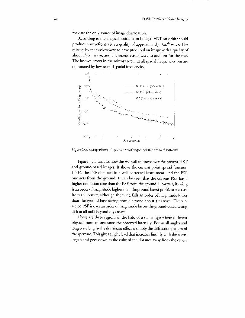
4o FOSI:Frontiersof Space Imaging
they are the only source of image degradation.
According to the original optical error budget, HST on-orbit should
produce a wavefront with a quality of approximately i/zo th wave. The
mirrors by themselves were to have produced an image with a quality of
about I/30th wave, and alignment errors were to account for the rest.
The known errors in the mirrors occur at all spatial frequencies but are
dominated by low to mid spatial frequencies.
10 j I I , I '
10:4t WFPC2PC(Corrected)
_-"'77-t,- _, WFPC-1(Aberrated)10_I GB(1arcsecseeing)
{
_g 10 ,IIii
, , J i !10*0 1 2 3 4 5 6
Arcseconas
Figure 3.2. Comparison of optical-wavelength point spread functions.
Figure 3.2 illustrates how the AC will improve over the present HST
and ground-based images. It shows the current point spread function
(PSF), the PSF obtained in a well-corrected instrument, and the PSF
one gets from the ground. It can be seen that the current PSI; has a
higher resolution core than the PSF from the ground. However, its wing
is an order of magnitude higher than the ground based profile at z arcsec
from the center, although the wing falls an order of magnitude lower
than the ground base-seeing profile beyond about 3.5 arcsec. The cor-
rected PSF is over an order of magnitude below the ground-based seeing
disk at all radii beyond o. 5 arcsec.
There are three regions in the halo of a star image where different
physical mechanisms cause the observed intensity. For small angles and
long wavelengths the dominant effect is simply the diffraction pattern of
the aperture. This gives a light level that increases linearly with the wave-
length and goes down as the cube of the distance away from the center
3. O,otical Telesco/_eAssembly 41
of a point image. At larger distances from the star or at shorter wave-
length, we expect to start seeing the effects of the mirror microroughness
structure and polishing imperfections, which vary approximately as the
inverse square of the wavelength and as the inverse of the square of the
scattering angle. Both of these effects fall offrapidly enough that beyond
about z arc minutes we expect the halo in the image to be dominated by
dust scattering from the primary mirror. (Approximately 5% of the area
is covered by particles 5 to zoo lum in size.) Note that this region of the
PSF mode of the AC is outside that observed directly even by the pro-
posed wide field, so only sources outside the field of view of the detector
would lead to scattered light dominated by the dust on the optics.
There are some effects that are intrinsic to the present PSF and that
might be avoided or mitigated in the AC by design. One is the simple
fact that the surface ofa CCD or photocathode is shiny and reflects light
back up through the optical system. In the case of WFPC and in some
modes of WFPC I1, this light is reflected almost back upon itself.' it hits
the filter and then returns to the detector as an expanding cone of light.
The result is a large halo around any point source with about the diam-
eter of the chip and containing about five percent of the light.
This ghost is clearly unacceptable in high-contrast fields. For ex-
ample, it could mask an extended source to be imaged in the neighbor-
hood of a bright object. The problem can easily be controlled either by
tilting the detector slightly within the constraints of maintaining focus,
or better, by tilting the filters so that the reflected light is steered awayfrom the detector into baMes.
For the current instruments, the ghost dominates the wings of the im-
age profile. This was not expected before launch. This region of the ina-
age of the PSF was expected to be dominated, at short wavelengths at least,
by scattering from the mirror surface. In fact we find that the scatter from
the mirror surface is between five and ten times lower than predicted and
may not even have been detected yet. The level of light that is observed
in the wings outside of the ghost is consistent with a ghost of the ghost.
If this ghost is eliminated, considerable benefit may be obtained by the
installation ofa apodizing coronagraph to suppress the PSF wings.
3.3 Focus STABILITY
The telescope is known to gradually shrink as a result ofdesorption
of water from the graphite-epoxy metering truss that connects the pri-
42 FOShFrontiersofSpaceImaging
mary and secondary mirrors. The rate ofdesorption is now of order one
micron per month, and appears to be approximately constant. This is
not a problem for the AC because it can be corrected by periodic adjust-
ments of the secondary mirror.
Additionally, there appears to be a "breathing" variation in focus
with an orbital time scale. Observations both in the FOC and the
WFPC taken within the same orbit show changes in focus with a peak-
to-peak amplitude corresponding to about five microns on the second-
ary mirror, or half a millimeter in focus. This difference is 1/20 th of a
wave. If the effect is limited to such changes, and we are able to focus at
the middle position, the largest focus error is I/4 oth of a wave, which
would represent an acceptable amount relative to an overall diffraction-
limited budget of I/I3 th wave. This assumes that slow focus changes can
be taken out accurately by moving the secondary mirror.
A peak-to-peak amplitude zx larger has been observed in one case in
August _992. Frequent changes of this magnitude would represent a seri-
ous threat to the error budget of any instrument that is not capable of
autonomous focus. At this stage we see no compelling need for an au-
tonomous focusing mechanism in the AC. If the effect develops a larger
amplitude and frequency than we presently believe, it will become obvi-
ous in observations by the WFPC II.
The amplitude of the short term component of the breathing has
been correlated with the forward light shield temperature (present value
minus the average over the last orbit). This correlation could be used for
an internal open loop control of AC focus if autonomous focussing
should prove necessary.
WFPC II does not have any internal focus mechanism and relies on
the telescope's secondary mirror to provide all of its focusing capability.
An advanced radial camera could operate on the same assumption. On
the other hand, if the advanced camera is an axial instrument, it will re-
quire its own focus mechanism in order to assure confocality with
WFPC II. The absolute focus of the telescope will be known to about
i mm when uncertainties in the COSTAR and WFPC II focus are taken
into account.
ACKNOWLEDGEMENT
Christopher Burrows was the lead author of chapter 3.
43
4. PointingPerformance
Unlike with ground-based telescopes, for which atmospheric 'seeing'
is the major source of image degradation, pointing errors are the
dominant source for diffraction-limited telescopes in space. We find
that except for disturbances caused by the solar arrays, which are due
to befixed, and except for requiring relatively bright guide stars, the
current pointing performance of Hubble Space 7"elescope (HS T) is
much better than expected before launch. The current line-ofsight
stability is adeqtmte for the Advanced Camera (AC), assuming the
solar array problem is eliminated by replacing the arrays.
Adeqtmte guide stars will be available for the AC only if it is in-
stalled in an a.x'ial bay.
Although not strictly required, an autonomous guiding feature #2
the AC, would offer insurance against the degradation of the exist-
ing pointing system, allow higher time resolution by synchronousscanning, and provide efficient and precise sub-stepping for recover-
ing spatial resolution in a wide-field camera mode with coarsely-
spaced pixels.
s shown in figure 4.I, pointing errors distribute the light from apoint source over a larger area and reduce the intensity of the
image peak, which is to say its Strehl ratio. (See chapter 3.z.)
Figure 4.z, which shows the Strehl ratio of an optically perfect Hubble
Space Telescope (HST) as a function of the magnitude of the pointing
errors, indicates that pointing errors should not be more than a few
milliarcseconds (mas) in order to maintain diffraction-limited quality in
the ultraviolet (UV). The design specifications for the HST Pointing
Control System (PCS) called for a pointing error over 24 hours of less
than 7 mas rms (root mean square). At the time, this level of image sta-
bility was unprecedented in either ground telescopes or space platforms,
and achieving it was one of the major challenges in the HST develop-
ment project. In this chapter we examine how this requirement has been
met--and exceeded---on orbit and why we find the pointing quality

44 FOSI: Frontiers of Space Imaging
60 40 -20 XG
Milliarcseconds
Figure 4.1. Effects ofjitter on a perfect diffraction limited image.
_OOnm
_/ 4 mas _ "-.._OQnm
c!_ _OOnm
' } / _ '0 I ) [)()F_ 0.010 ( .01FJ _ ta.lO OZC:
Standard Deviation of Jitter (milliarcseconds)
Figure 4.2. Effects of jitter on the Strehl ratio of a perfect image as a
function of wave length.
appears adequate for the proposed Advanced Camera (AC). We also ex-
amine the availability of guide stars and the potential benefits of an au-
tonomous guiding function for the AC to provide insurance and en-
hanced scientific capability.
4.i DESCRIPTION OF THE GUIDING SYSTEM
The PCS uses several sources to determine the attitude of HST: sun
sensors, magnetic sensors, external star trackers, field star trackers and
gyroscopes. During observations, however, the stabilization of the line-
of-sight (in other words, 'guiding') relies solely on the gyroscopes with a
4. />ohlting Perfi)rmance 45
periodic position update supplied by two (of three) Fine Guidance Sen-
mrs (FGS), which track two guide stars in the fdd of view (FOV) of the
telescope. (Very short observations can bc guided using the gyroscopes
alone, i.e. without FGS update; short term drift is typically less than
I mas per second.) Attitude corrections are applied to the entire space-
craft by' varying the speed of spinning flywheels called 'reaction wheels'.
An FGS has two operational modes: a coarse mode ('coarse track')
based on image scanning and a fine mode ('fine lock') based on iuter-
ferometric fringe tracking. Fine lock is the only mode capable of provid-
ing the image stability required for high spatial resolution. Because fine
lock has a limited capture range, coarse track is used as a preliminao, step
in the acquisition sequence to center the guide star before initiating the
fine lock mode. Coarse track is more robust than fine lock, and can also
be used as the primary guiding mode in observations not requiring the
ultimate in pointing perfbrmance.
4.I.I GUIDE STAR ACQUISITION PROCEDURE
A ,typical guide star acquisition begins with the telescope slewing to
the desired field, usually followed by refining the attitude by a fixed-
head star tracker update. At that point, the residual attitude error is
about lz". Next, one FGS starts to search R)r the first guide star using a
spiral pattern with its 5" x 5" instantaneous FOV. When it finds a star of
the correct brightncss, the FGS tracks it in coarsc track mode, and thc
second F(;S searches for its guide star. When the second star is fbund, its
position relative to the first provides a check. If'the guide star pair is not
verified, the search resumes. If the pair is confirmed, the FGSs continue
in coarse track if that is the desired mode, other,vise they transition tofine-lock mode.
The actual duration of the guide star acquisition process depends on
the guiding mode and on how long the star search lasts. For first-time
acquisitions, typical durations are I8o seconds fi)r coarse track and z8o
seconds for fine lock. Subsequent re-acquisitions in either coarse track or
fine lock _pically require 40 seconds less than first-time acqt, isitions.
If the guide star acquisition process fails because one of the two guide
stars cannot be fbund or tracked, a second attcmpt is made on a dif}erent
pair of guide stars. Up to three guide star pairs can be tried in one acqui-
sition sequence. In practice, failed acquisitions are rare, and generally
only one guide star pair is planned for each observation.
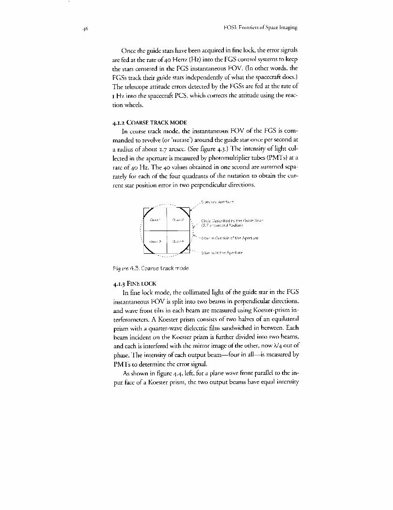
46 FOSI:FrontiersofSpace Imaging
Once the guide stars have been acquired in fine lock, the error signals
are fed at the rate of 4o Hertz (Hz) into the FGS control systems to keep
the stars centered in the FGS instantaneous FOV. (In other words, the
FGSs track their guide stars independently of what the spacecraft does.)
The telescope attitude errors detected by the FGSs are fed at the rate of
I Hz into the spacecraft PCS, which corrects the attitude using the reac-
tion wheels.
4.1.2 COARSE TRACK MODE
In coarse track mode, the instantaneous FOV of the FGS is com-
manded to revolve (or 'nutate') around the guide star once per second at
a radius of about z. 7 arcsec. (See figure 4.3.) The intensity of light col-
lected in the aperture is measured by photomultiplier tubes (PMTs) at a
rate of4o Hz. The 40 values obtained in one second are summed sepa-
rately for each of the four quadrants of the nutation to obtain the cur-
rent star position error in two perpendicular directions.
/ _ argsec aperture
Quad 1 Q_Jad 2 • _ Circle Described by the Guide Star
',F -'_ (27 arcsecond Radius)
.';_'" Star is Outside of the Aperture
, ;'t_*d 3 Qtaa4 ,
_, Star- is in the Aperture/x_
Figure 4.3. Coarse track mode
4.L3 FINE LOCK
In fine lock mode, the collimated light of the guide star in the FGS
instantaneous FOV is split into two beams in perpendicular directions,
and wave front tilts in each beam are measured using Koester-prism in-
terferometers. A Koester prism consists of two halves of an equilateral
prism with a quarter-wave dielectric film sandwiched in between. Each
beam incident on the Koester prism is further divided into two beams,
and each is interfered with the mirror image of the other, now X/4 out of
phase. The intensity of each output beam--four in all--is measured by
PMTs to determine the error signal.
As shown in figure 4-4, left, for a plane wave front parallel to the in-
put face ofa Koester prism, the two output beams have equal intensity

4. l'ointing Pe_ibrman,'e 47
o/V
Figure 4.4. Fine lock mode. At [eft, wavefront parallel to input face, at
right the wavefront is tilted.
('grey' because of the )v/4 retardation). If the plane wave is tilted, how-
ever, figure 4.4 right the outer portion of one of the output beams will
tend to experience constructive interference (higher overall intensity),
while the outer portion of the other output beam will tend to experience
destructive interference (lower over'all intensity). The position error sig-
nal is formed by combining and normalizing the intensity in the two
channels ((A-B)/(A+B)). The error signal as a function of wave front tilt,
commonly called an 'S-curve', is illustrated in figure 4.5- The theoretical
modulation is +_0.7 for a peak-to-peak separation of 43 mas, which is the
diffraction limit of the telescope at wavelength 6ooo A.
The problem with fine lock is its limited dynamic range--about
80 mas--which renders this mode very sensitive to vehicle jitter. Atti-
tude disturbances can throw the pointing out into the S-curve aprons,
where the error signal does not provide the information required to re-
cover the central null, i.e., lock is lost.
I
Figure 4.5. Theoretical error signal of the fine lock interferometer.

48 FOSI: Frontiers ofSpacc lmaging
4.I.4 EFFECT OF SPHERICAL ABERRATION ON THE GUIDING SYSTEM
The spherical aberration in the HST primary mirror redistributes light
from the core of a star image into a surrounding halo. In coarse track, this
means starlight falls outside the FGS instantaneous FOV--6o% or about
halfa magnitude loss averaged over a nutation cycle. Also, the coarse track
modulation (sensor gain) is reduced as a result of image wings still present
in the aperture when the image core is outside. Hence, even for brighter
stars, the error signal is not as strong as expected before launch, and the
control system response is degraded.
in the case of fine lock, the efliect of the spherical aberration is more
subtle. In principle, the 'mirror image' interferometric system is insensi-
tive to any symmetric aberration such as focus or spherical aberration.
However, this is not true in practice due to small misalignments be-
tween the incoming beam and the Koester prism axis. For a focus
change, these misalignments cause a shift in the position of the S-curve
null, and for spherical aberration, they reduce the error signal modula-
tion. A typical real S-curve is shown in figure 4.6, which, when com-
pared to the ideal one in figure 4.5, indicates how much internal
misalignments affect both the amplitude and the shape of the S-curves.
Due to the reduction of modulation and the secondary maxima, fine
lock cannot be reliably obtained with the full pupil, and the use of the
pupil stop (2/3 full aperture) to reduce the efl-_ct of spherical aberration is
man&to W on an operational basis.
Figure 4.6. Typical actual S-curves. Dotted, an S-curve obtained with thefull pupil. It is so degraded than reliable guiding is not possible. Solid, an S-curve obtained with a 2/3 aperture stop shows how proper modulationcan be restored.

4. Pointing Pe_ormance 49
The HST guiding system was designed to operate on stars down to
I4.5 magnitude in order to ensure an 85% probabili_ of finding guide
stars near the galactic pole, where the distribution of field stars is most
sparse. This specification was based both on the statistical occurrence of
stars as a function of apparent magnitude and on the expected frequency
of unidentified binary stars that would deny fine lock. Due to the neces-
sity to mask the pupil used by the FGS to 2/3 of its full diameter for ad-
equate modulation in fine lock, guidance is not reliable on guide stars
fainter than i3tll magnitude in fine lock. When an adequate pair of guide
stars--stars bright enough and properly separated----cannot be found,
the observation is either done in coarse track (if acceptable to the ob-
server) or rescheduled later in the year for a different roll configuration.
Currently, out of approximately 7oo observations per year that are re-
quested in fine-lock guidance, 30 are executed in coarse track, IOO are re-
scheduled later in the year, and only 2 or 3 are not executed at all for lack
of guide stars, whether in fine lock or coarse track.
4.i.5 BINARY GUIDE STARS
Somewhat counteracting the loss in FGS sensitivity due to spherical
aberration, it was a pleasant surprise to find after launch that binary
guide stars have much less effect on fine-lock guidance than expected.
Missed acquisitions or repetitive losses of lock attributable to the possi-
bility that guide star is a binary represent only about Io% of all acquisi-
tions. Binary stars can distort S-curve significantly, but the effects on
guidance has now been shown to have been grossly overestimated. This
development has obviated the need to uplink several pairs of guide stars
to ensure acquisition success, and currently essentially all star acquisi-
tions use only one pair.
4.2 CURRENT GUIDING PERFORMANCE
4.2.1 MEASURING HST's LINE-OF-SIGHT JITTER
HST pointing jitter can be analyzed routinely using telemetry data
from the gyroscopes and the FGSs, which in principle are the best indi-
cators as they sense the line-of-sight directly through the entire optical
train. The gyroscopes sense only the overall body inertial attitude, which
may differ from the line-of-sight orientation due to the motion of opti-
cal components. In practice, however, the optical components contrib-
ute very little to jitter, and the gyroscopes and FGSs tend to agree on the
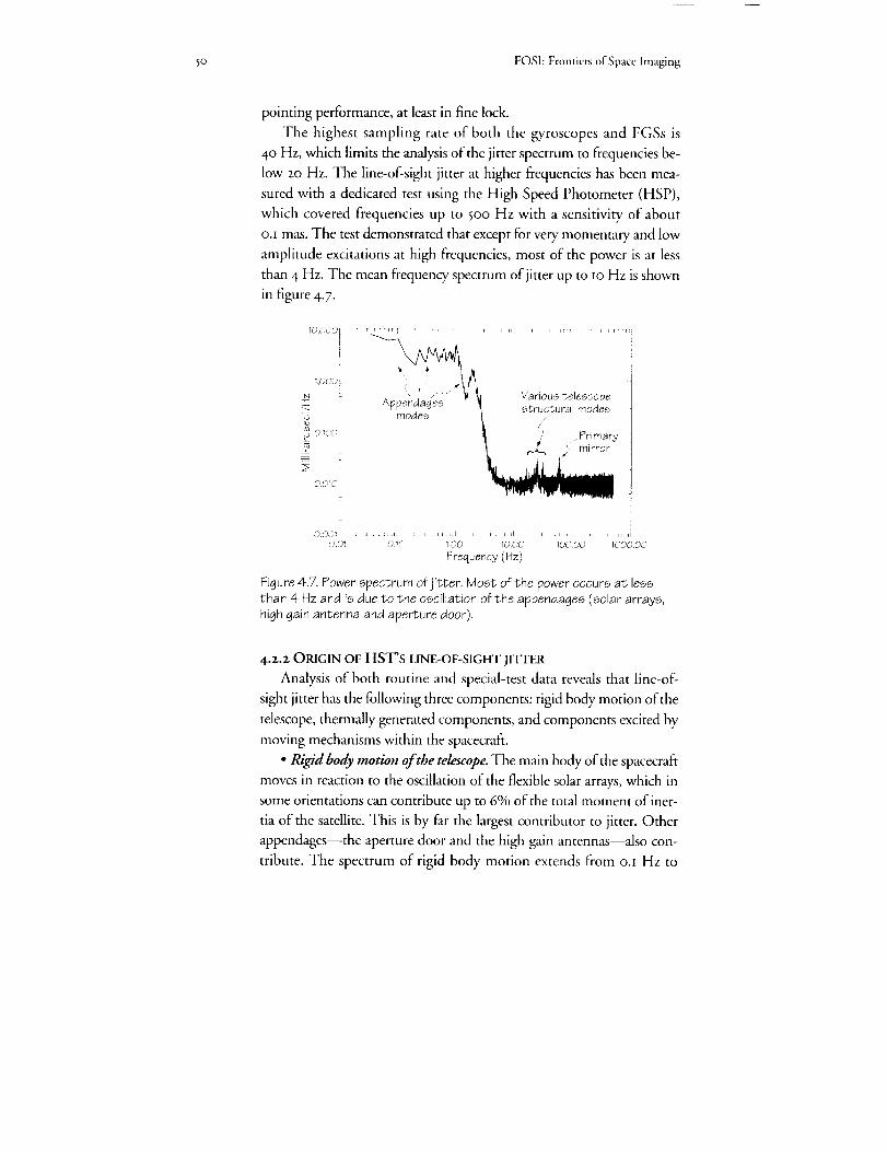
50 FOSI: Frontiers of Space Imaging
pointing performance, at least in fine lock.
The highest sampling rate of both the gyroscopes and FGSs is
4o Hz, which limits the analysis of the jitter spectrum to frequencies be-
low 2o Hz. The line-of-sight jitter at higher frequencies has been mea-
sured with a dedicated test using the High Speed Photometer (HSP),
which covered frequencies up to 5oo Hz with a sensitivity of about
o.i mas. The test demonstrated that except for very momentary and low
amplitude excitations at high frequencies, most of the power is at less
than 4 Hz. The mean frequency spectrum of jitter up to ro Hz is shown
in figure 4-7.
10,000 tI
:,000;
O_QOL_
0.010
000_ J
O.O!
i
Various telescopestructural modes
,, Primawj<, mirror
0._0 100 1000 10,o.00 T000,00
Frequency (Hz)
Figure 4.7. Power spectrum of jitter. Most of the power occurs at less
than 4 Hz and is due to the oscillation of the appendages (solar arrays,high gain antenna and aperture door).
4.2.2 ORIGIN OF HST's LINE-OF-SIGHT JITTER
Analysis of both routine and special-test data reveals that line-of-
sight jitter has the following three components: rigkt body motion of the
telescope, thermally generated components, and components excited by
moving mechanisms within the spacecraft.
• Rigid body motion of the telescope. The main body of the spacecraft
moves in reaction to the oscillation of the flexible solar arrays, which in
some orientations can contribute up to 6% of the total moment of iner-
tia of the satellite. This is by far the largest contributor to jitter. Other
appendages--the aperture door and the high gain antennas--also con-
tribute. The spectrum of rigid body motion extends from o.I Hz to

4. Pointing Pe_fbrmance fl
about 4 Hz. Rigid body motion of the telescope is especially strong dur-
ing earth terminator passages, when the solar arrays experience a thermal
shock. During the rest of an orbit, it results from secondary solar array
disturbances, thermal creaks in the outer body of the spacecraft, and
PCS instability residuals.
• Thermally-generated excitations propagating to the optical train.
The tilting vibration of the primary mirror on its support is particularly
noticeable at about 6o Hz, and various modes in the telescope support
structure contribute in the range ofu to 3o Hz. However, no vibration
of the secondary mirror has been identified. These vibrations in the opti-
cal train and their supporting structure appear to be excited by shocks
induced by the solar array disturbances and/or by thermal creaks within
the outer body. The resulting image motion has small amplitude--a ffw
mas--and damps quickly with no significant effect on observations.
• Internally-generated excitationspropagating to the optical train or
the science instruments. In principle, every active device on board the
spacecra_reaction wheels, antennas, and tape recorders, as well as the
mechanisms in the guiding systems and the Sis--can potentially excite
jitter. Because they are always operative and constantly changing speed,
the influence of the reaction wheels is difficult to separate from the back-
ground excitation created by the solar arrays. Of the other devices, only
the tape recorder produces a clearly identified effect. While in use at the
normal record/playback tape speed, the tape recorder induces a continu-
ous vibration of the line of sight at 65 and 3oo Hz with an amplitude of
I tO 2. mas.
4.z.3 MAIN POINTING DISTURBANCES
The largest pointing disturbances occur twice per orbit at the passage
between sunlight and darkness. The thermal shock to the solar arrays
had been grossly underestimated before launch. The main body of the
spacecraft reacts with an attitude displacement of several tenths of anarcsecond and oscillates for about two minutes at o.l and o.6 Hz, which
are the frequencies of the main torsional and in-plane bending modes of
the solar arrays. The PCS has now been tuned to minimize this effect,
but the limited bandwidth of the PCS does not permit full cancellation.
In addition to the terminator passagm, the telescope pointing exhib-
its relatively frequent, abrupt, non-oscillatory glitches. These distur-
bances are lo to 5o mas in amplitude, last 3 to 5seconds and occur at ap-
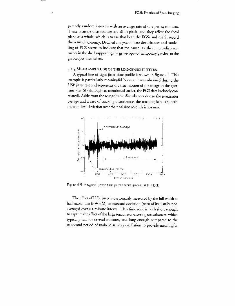
5z FOSh Frontiers of Space lmaging
parently random intervals with an average rate of one per I4 minutes.
These attitude disturbances are all in pitch, and they affect the focal
plane as a whole, which is to say that both the FGSs and the SI record
them simultaneously. Detailed analysis of these disturbances and model-
ling of PCS seems to indicate that the cause is either micro-displace-
ments in the shelf supporting the gyroscopes or temporary glitches in the
gyroscopes themselves.
4.2.4 MEAN AMPLITUDE OF THE LINE-OF-SIGHT JH'TER
A typical line-of-sight jitter time profile is shown in figure 4.8. This
example is particularly meaningful because it was obtained during the
HSP jitter test and represents the true motion of the image in the aper-
ture of an SI (although, as mentioned earlier, the FGS data is closely cor-
related). Aside from the recognizable disturbances due to the terminator
passage and a case of tracking disturbance, the tracking here is superb:
the standard deviation over the final 8o0 seconds is 2.9 mas.
2ooo
5_ o
_ 2o
Tracking disturbance []
0 200 40Q 800 1000 120Q
Terminator passage
b z9 _as _ms q
t
600
Time in Seconds
Figure4.8. A typical jitter time profile whileguiding in fine lock.
The effect of liST jitter is customarily measured by the full width at
half maximum (FWHM) or standard deviation (rms) of its distribution
averaged over a _-minute interval. This time scale is both short enough
to capture the effect of the large terminator-crossing disturbances, which
typically last for several minutes, and long enough compared to the
Io-second period of main solar array oscillation to provide meaningful
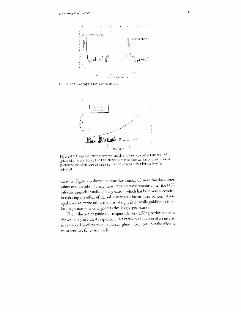
4. Pointing Pe_)q_rmance 53
Figure 4.9. Averaojejitter during an orbit
1! I;: I?,
Itdagnitu,_e
Figure 4._0. Typical jitter in coarse track and fine lock as a function of
guide star magnitude. The two curves are representative of best guiding
performance that can be obtained when vehicle disturbance level isrqfnirqai.
statistics. Figure 4-9 shows the time distribution of mean fine-lock jitter
values over an orbit. (These measurements were obtained after the PCS
software upgrade installed on day 92.m7, which has been very successful
in reducing the effect of the solar array terminator disturbances.) Aver-
aged over an entire orbit, the line-of sight jitter while guiding in fine-
lock is 3.5 mas--twice as good as the design specification!
The influence of guide star magnitude on tracking performance is
shown in figure 4.IO. As expected, jitter varies as a function of an inverse
square root law of the main guide star photon connects, but the effect is
most sensitive for coarse track.
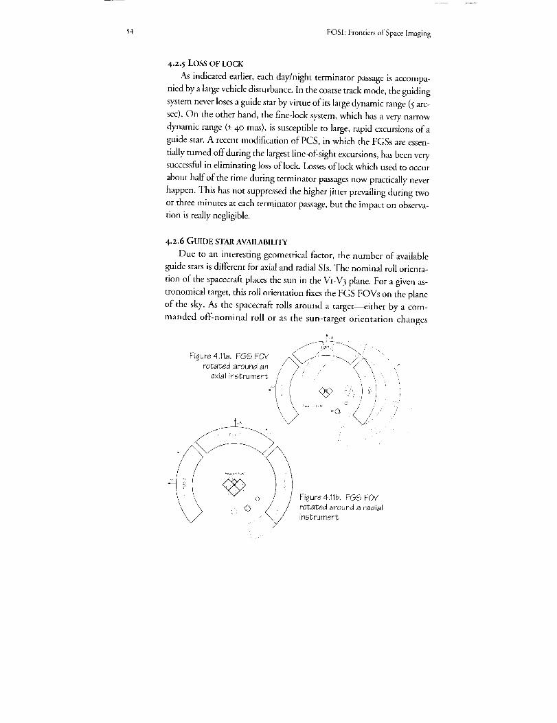
54 FOShFrontiersof Space Imaging
4.2.5 LOSS OF LOCK
As indicated earlier, each day/night terminator passage is accompa-
nied by a large vehicle disturbance. In the coarse track mode, the guiding
system never loses a guide star by virtue of its large dynamic range (5 arc-
sec). On the other hand, the fine-lock system, which has a very narrow
dynamic range (+ 40 mas), is susceptible to large, rapid excursions of a
guide star. A recent modification of PCS, in which the FGSs are essen-
tially turned off during the largest line-of-sight excursions, has been very
successful in eliminating loss of lock. Losses of lock which used to occur
about half of the time during terminator passages now practically never
happen. This has not suppressed the higher jitter prevailing during two
or three minutes at each terminator passage, but the impact on observa-
tion is really negligible.
4.2.6 GUIDE STAR AVAILABILITY
Due to an interesting geometrical factor, the number of available
guide stars is different for axial and radial Sis. The nominal roll orienta-
tion of the spacecraft places the sun in the VI-V 3 plane. For a given as-
tronomical target, this roll orientation fixes the FGS FOVs on the plane
of the sky. As the spacecraft rolls around a target--either by a com-
manded off-nominal roll or as the sun-target orientation changes
Figure 4.11a. FGS FOV ___--'_x"
rotated around an /J7 / _ _/"
axial instrument [/' : \
/
0 Figure 4.11b. FGS F0Vrotated around a radialinstrument

4. Pointin_ peoCormance SS
through the seasons--the FGS FOVs move relative to the target, which
makes more guide stars available to support the observation. As illus-
trated in figures 4.iia and 4.llb, this effect is much more dramatic for a
roll around an off-axis than an on-axis target, which means that more
guide stars are available to an axial than to a radial SI. This is shown
quantitatively in figures 4.r2 and 4.I 3, which compares guide star prob-
abilities for typical axial and radial Sis. As summarized in table 4.1, the
typical axial SI has a significantly higher probability of finding a pair of
I3 tt_ magnitude guide stars at mid- and high galactic latitudes.
G._ide Star Den<ties from ,Operat o_a Guide Star Catalog
5
11 12 13 14 15 IS
!vlag qittJ_e
Figure 4.12. Guide star
densities per Fgs field ofview as a function of
magnitude and galactic
latitude (b)
FIF_5 ;a*:ial :'a,,
Figure 4.13. Probability of
finding an adequate pair ofguide stars as a function of
magnitude for an axial or a
radial bay instrument
Table 4.1. Effect of limiting guide stars to 13 > magnitude
Guide star density(13> magnitude guide stars/FGS FOV)
Axial SI success probability(1pair of guide stars)
Radial SI success probability(1pair of guide stars)
Galactic Latitude
15°<b<30 ° b>30 °
0.55 0.4
99% 95%
75% 55%

56 FOSh Frontiers of Space Imaging
4.3 IMPROVEMENTS EXPECTED FROM THE REPAIR MISSION
On the first servicing mission, new solar arrays will installed that
have been designed to be insensitive to the thermal shock of the day/
night transition. This should eliminate all terminator-induced high jitter
as well as losses of lock. If this is achieved, we expect the amplitude of
line-of-sight jitter to be about 3 to 4 mas routinely--twice as good as the
original specification and adequate not to degrade the point-spread
function significantly even a _.= noo A, the shortest wavelength we en-
vision for the AC. The small and random tracking discontinuities will
likely still remain, however, but their scientific impact on AC observa-
tions will be minimal.
4.4 FOCAL PLANE STABILITY AND CONTRIBUTION BY THE
SCIENCE INSTRUMENTS
In addition to pointing errors which strictly refer to the motion of
optical images delivered at the focal plane, focal plane or FGS instabili-
ties can add their own contribution. Indeed, there is evidence that for
long exposures, the image can move by somewhat more than what the
simple line-of-sight jitter would indicate. Whether this is due to effects
internal to the instruments, drift in the FGS, changes in the telescope
optical train, or instabilities in the focal plane is not yet clear.
For example, there is the suspicion that the FGS may experience
slight thermally-induced drift at the milliarcsecond level. There is also
one HSP long observation which exhibited a flux variation which could
be attributed to a motion of the HSP respective to the FGS, although
there are alternate explanations (focus changes). Concerning the cam-
eras, image size measurements do not quite match the values predicted
from the simple line-of-sight jitter. Overall these effects appear to be on
the order of io mas at the most.
In the current design of HST, there is no provision for the pointing
system to guide these effects out since the FGS can only correct for er-
rors that affect the focal plane image as a whole. Only a guiding system
internal to an instrument would be able to correct for these focal plane
drifts or SI internal instabilities.
4.5 ADVANTAGES OF AN AUTONOMOUS GUIDING FUNCTION IN
THE AC
Even if line-of-sight jitter is reduced to a fully acceptable level with
4. Pointing Pe_ c°rmance 57
the repair mission, an autonomous guiding function in the AC would
have multiple advantages:
i. A local guiding would guarantee a short term line-of-sight stability
to a level better than what can be provided by the FGS/PCS, because
any PCS residual errors would thus be corrected. Mthough these re-
sidual errors may be brought down to within specifications with the in-
stallation of the modified solar arrays it is likely that the spacecraft will
still be sensitive to some extent to thermal creak affecting either still the
solar arrays or the spacecraft body. Sudden disturbances of the type de-
scribed above in section 4.2.3 would also be eliminated.
2. Local guiding would guarantee the long term line-of-sight stability
which is affected by the differential motion of the FGS and the SI. This
thermally-driven effect is not fully characterized yet but thought to be onthe order of several milli-arcseconds over a time scale of several orbits (due
to the thermal inertia of the spacecraft). The current FGS based guiding
system is, by design, incapable of detecting these errors and only a system
internal to an SI can compensate for them.
3. An autonomous guiding system would serve as a backup, in case of
failure or degradation of the primary FGS-based system. Our current
system is resilient to failures, and there exist several levels of backup
modes which would maintain some sort of guiding capability. Examples
of these backup modes are: only two FGS, FGS with only one axis con-
trol, or one FGS combined with FHST or gyros. Most backup cases
would lead to a guiding degradation. An autonomous guiding capability
would act as an insurance, and guarantee that even in the case of backup
operation, the line-of-sight stability of the AC is kept at the highest level.
4. It may be possible to feed the error signal back to the PCS in order
to control the entire spacecraft. This could be advantageous in order to
maintain a high guiding quality for all the SI's in case of degradation of
the primary (FGS-based) guiding mode. The AC being then only used a
guider.
5- An autonomous system which allows precise and rapid control of
the line-of-sight beyond the capability of the normal guiding system, has
many potential astronomical applications. One example is increasing
the time resolution beyond the nominal frame rate of the camera by syn-
chronous scanning. In this technique, the line of sight is rotated on the
imaging camera and variable sources can be detected by measuring the
change in intensity over the circular trace.

5g FOSI: Frontiers of Space Imaging
6. Increasing the efficiency of the observatory by allowing the sys-
tematic use of the FGS coarse track mode instead of fine lock, the higher
associated jitter being compensated by the autonomous system. Coarse
track leads to essentially full sky coverage, and saves about IOOseconds in
acquisition time.
7. Increasing the efficiency of the observatory by allowing faster step
and dwell than what the current pointing system is capable of (2 arc_sec-
ond per second).
4.6 CONCLUSION
In conclusion, we consider that once the terminator passage distur-
bances will have been eliminated by the replacement of the solar arrays,
pointing should be well within the specification for the AC. Still, although
not strictly required, a guiding system integral to the AC would offer an
insurance against pointing degradation, improve overall observing effi-
ciency and allow sophisticated observational techniques that the current
slow and somewhat imprecise pointing system cannot offer. Concerning
guide star availability, full sky coverage can only be guaranteed if the AC
is in an axial bay.
ACKNOWLEDGEMENT
Pierre Bely was the lead author of chapter 4.

S9
5. AdaptiveOptics& HST'UniquenessSpace'
Adaptive optics at ground-based observatories p_wnises enhancedresokttion and raises"the question: What are the unique imaging
aspects of the Hubble Space Telescope (HST)? Upon ret,ieu,, we
find adaptive optics is an inherent[y limited movnomica] so]ution
compared with space imaging. An advanced camera _vmexploit the
advantages of space to provide scientific benefits unchalh'nged by
ground-based te[escopes.
Adaptive optics offers greatest gains h_ the infi'ared, u,ith progres-
sively smaller gains in the green and Hue. Adaptit,e optics'provides
only sma// fields of vieu,, which rules out crisp images fbr accurate
photometry of extended objects like pkmets and ckcsters of stars and
go&vies. Adaptive optics improves on]y the centra/ part of the im-
age, and the remaining halo of scattered light degrades the obtain-
ab[e contrast and dynamic range for detecting f#nt companions
and studying subtle features on extended objects.
[IS T pe_forms better than adaptive optics in p_vviding a stable, su-perb image over a u,ide field of vieu, from far ultraviolet to near
infi'ared wavelengths.
daptive optics (AO) is a technique that aims to compensate for
the aberrations caused by the Earth's atmosphere in real-time.he measurement and compensation cycle is I to IO millisec-
onds (reset) of time. This approach is different from active optics, which
aims to provide corrections to mirrorfigure errors on a slower time scale.
AO is intriguing bccause it has the potential to completely remove
atmospheric distortions attd to achieve diffraction-limited imagery. The
outlook for AO is promising: it is making technical strides, its funding
levels are increasing, and it should attain the status of Gcility instrumen-
tation at many ground-based observatories by the end of the I99OS. In
view of these developments, this study of the Advanced Camera (AC)
for the Hubble Space Telescope (HST) must confront the following is-
6o FOSI: Frontiers of Space Imaging
sue: How will ground-based AO restrict the 'uniqueness space' of the
AC? It would be foolish to implement a capability in space that could be
achieved at lower cost on the ground.
To approach the uniqueness issue, we have synthesized several
sources of information. We have reviewed the responses from the com-
munity to our broadcast letter soliciting ideas about the AC, current
adaptive optics research results, and recently declassified military tech-
nology. Our initial assessment was that the role of AO would depend
greatly on the funding and focus of the major research groups, which
prompted us to conduct a supplemental survey of the AO community
before forming our final prognosis.
In this chapter, we begin by stating the imaging attributes of HST
that define its potential uniqueness space. We then explain the atmo-
spheric distortion problem, present the generic AO approach, identify
its physical limitations, and discuss the cost drivers for its implementa-
tion. We summarize the major adaptive optics projects and their current
goals. On the basis of all this information, we give our prognosis for AO
and delineate the performance aspects of the AC that will remain un-
questionably unique and valuable for science.
5.I THE ADVANTAGES OF SPACE-BASED IMAGING
Two of the main advantages of a space-based telescope are wave-
length coverage and the potential for a point-spread function (PSF)
characterized by three attributes: (i) high resolution, i.e. a diffraction-
limited core, (z) low scattering, i.e. diffraction-limited wings, and (3)
wide field of view (FOV) over which the PSF does not vary.
Useful ancillary descriptors of the PSF are (a) the encircled energy
function (EEF), which is the definite integral of the PSF as a function of
the radial distance from the PSF centroid, (b) the full-width at half-maxi-
mum (FWHM), which for a diffraction-limited system is approximately
k/D where k is the wavelength of light and D is the diameter of the tele-
scope aperture, and (c) the Strehl ratio, which is the ratio of the intensity
of the actual image peak to that of the theoretically perfect image for that
system. We will use the Strehl ratio rather than the FWHM to measure
spatial resolution because it is more sensitive for nearly diffraction-limited
systems. The EEF is a useful shortform for comparing PSF wings.
The relative importance of resolution (Strehl ratio) and PSF wings
(EEF) depends on the imaging scenario. For instance, measurement of

_.Addptive Optics & LIST 'UniquenessSpace' 61
the separation of two equal-magnitude stars is primarily limited by reso-
lution because the stochastic uncertainty is dominated by the statistical
noise in the cores of the two source images. On the other hand, for faint
companions or low-contrast features in extended objects, both high
Strehl ratio and tight EEF may be necessary conditions for detection.
For surveys and sensitive photometry of scattered sources, the varia-
tion of PSF over the FOV is an important consideration, which for vari-
ous observations combine with high Strehl ratio or tight EEF or both as
performance requirements. Ideally, the PSF is the same over the entire
image plane, that is, the PSF is 'isoplanatic'.
Interestingly, the following sections will show that comparing the
expected I999 capabilities of ground-based AO with HST is similar to
comparing performance before and after correcting HST spherical aber-
ration. Ground-based AO will reach very high resolution, but its PSF
will be spatially varying and will exhibit a significant halo, which is
analogous to the present HST performance. Thus, our assessment of the
uniqueness of HST in I999--and the scientific benefits of capitalizing
on those strengths by building the AC---echo the prospects of the HST
as planned and the arguments for correcting the spherical aberration, as
is planned in late I993 on the first servicing mission.
5.2 OVERVIEW OF ATMOSPHERIC DISTORTIONS AND THE AO
APPROACH
During the propagation of light from an astronomical object to a
ground-based telescope, the wave front of the electromagnetic radiation
is effectively unperturbed in its transit through space (neglecting dust
obscuration and gravitational lenses). However, during the last 3° mi-
croseconds of the light's travel it encounters a distorting medium, the
earth's atmosphere. Fluctuations in the atmosphere's index of refraction,
due to temperature inhomogeneities, induce phase distortions on the
wave front. These effects occur throughout the troposphere, from the
ground up to an altitude of about IO kilometers (km). The aggregate ef-
fect is a phase-distorted wave-front surface that has a fractal-like appear-
ance. The wave-front surface is nearly same for all wavelengths due to
the weak wavelength dependence of the index of refraction of air. There
are three main parameters used to describe the atmospheric distortions:
the lateral coherence length, Po, the atmospheric correlation time, Zo,
and the isoplanatic angle, 0o.

6z FOSI: Frontiers of Space Imaging
5..?..I LATERAL COHERENCE LENGTH OF THE ATMOSPHERE, P0
The distortions in the wave-front surface can be described by the
phase structure function, which is the mean-square difference of the
phase between two points on a plane that is orthogonal to the propaga-
tion vector. The two points are considered 'out of phase' when the
mean-square difference is greater than I radian of phase angle; the sepa-
ration of the out-of-phase points is termed the lateral coherence length
of the wave front. For simplicity, the distortions are considered to be iso-
tropic and homogeneous, and the lateral coherence length is stated as a
scalar quantity, po. A practical and intuitive definition ofpo is the maxi-
mum aperture diameter that can attain a diffraction-limited PSF.
The phase of the wave front depends on wavelength, and longer wave-
lengths will have larger po. Due to the random-walk nature of phase sur-
face, 9o grows faster than the first power of wavelength. Using the most
widely accepted model of atmospheric turbulence (due to Kolmogorov),
one finds that po is proportional to k"L For one arcsec seeing, Po is ap-
proximately Io centimeters (cm) in the visible spectrum near 55oo fit.
5.2.2 ATMOSPHERIC CORRELATION TIME, zO
The wave-front distortions evolve in two ways. On short time scales,
the distortions can be considered to be frozen and blowing past the tele-
scope at some given velocity; this is termed the Rayleigh model of atmo-
sphere turbulence. In reality, the atmosphere is not frozen, and if one could
fly along with the wave front at its mean velocity, the wave front would
appear to evolve in a boiling fashion; this effect is Mintzer turbulence. For
AO, Rayleigh turbulence defines the correlation time of phase variation
over an po-sized subaperture or zone of the telescope entrance aperture.
Thus, the time over which the wave-front phase does not vary by more
than one radian, %, is simply po divided by the wind velocity, and
Zo _ kIL In the visible, at a good site with good seeing, Zo -2 to 5 msec.
5.z.3 ISOPLANATIC ANGLE, 00
If the atmospheric distortions were concentrated in a thin layer im-
mediately in front of the telescope, light from any angle in the FOV
would get the same distortion. Neglecting the effects ofobscuration, the
PSF would be the same for all angles (isoplanatic).
Unfortunately, for ground-based imaging, the atmosphere is 3-dimen-
sional and the distortions occur over a Io km tall volume above the tele-

y.Adapti_,eOptics O HST '_Imqz,e_J,:,-s.Space' 63
scope, which causes the distortions to be non-isoplanatic. To draw a simple
picture that gives a physical understanding of non-isoplanatism, let us
assume that all distortions occur in two thin layers---one immediately above
the telescope and a second layer that is io km above the telescope aper-
ture. Also,assume that po = 15cm in both layers. If the telescope looks directly
overhead, a star that is on-axis will experience a total distortion that is the
sum of the lower and upper distortions (after propagation of the upper
atmosphere distortion) and the effective po will be less than 15cm. For a
star off the zenith, the upper atmosphere distortion is shifted relative to
the lower atmosphere distortion and the overall distortion is different. At
an angle of 3 arcsec (3 arcsec -_ 2.5x IO"5radian = I5 cm/Io kin), the pro-
jected upper atmospheric distortion has shifted by a distance po- Thus, in
this simple model, the isoplanatic angle is 3 arcsec. In practice for the 3-D
atmosphere, the isoplanatic angle at visible wavelengths is typicatlly about
5arcsec; in the infrared (IR), 0o ranges from xo arcsec at I.o _m to 25 arcsec
at z.5 _rn. As for po and %, Oo is proportional to _."-'.
We note that at least one AO group is attempting to expand the
isoplanatic angle by using two or more adaptive mirrors, each conjugate
with a layer that may be producing a distortion. While this approach may
show promise if the layered atmosphere model has validity, the efforts are
embryonic and largely theoretical; their costs and limitations are not yet
well-defined, and we do not address this approach further in this report.
5.2,.4 SCHEMATIC DIAGRAM OF ADAPTIVE OPTICS SYSTEM
AO aims to correct for the atmospheric distortions by measuring
and compensating po size subapertures on a time scale shorter than _o.
The five main components of an AO system are shown in figure 5.I: (t) a
wave-front sensor that measures the atmospheric distortions using light
from a reference source, (z) a wave-front reconstructor that converts the
wave-front sensor measurements into a phase surface and sends informa-
tion on the required compensation to the adaptive elements, (3) a
deformable mirror that bends to correct the distortion, (4) a tip/tilt mir-
ror that is usually required to compensate the large image translations
that are outside the dynamic range of the deformable mirror, (5) the im-
aging (science) camera.
A_sseen in figure 5.1, these systems are usually arranged so that the
wave-front sensor looks at the wave front after correction; that is, it mea-
sures the residual wave-front error and commands the tip/tilt and

64 FOSI: Frontiers of Space Imaging
deformable mirrors to achieve a flat wave front.
There are various ways to measure the wave front, a variety of types
of deformable mirrors, and alternate approaches to wave-front recon-
struction. However, for current purposes, one only needs to be aware
that these differences are not drivers in terms of ultimate system perfor-
mance. While some approaches are more appropriate for more elemen-
tary AO, all systems have the same fundamental physical limitations,
which we discuss in the next section.
Fig. 5.1 Main components of
adaptive optics systems. The AO
system attempts to correct inreal-time the distortions that
occur in the troposphere, domi-nated by boundary layer effects
and the jet stream (at the
tropopause, about 10 km abovesea level).
The critical components of an AOsystem are the deformable mirror
(DM) and the wavefront sensor
(WFS). The most advanced DM inuse today has about 500 actua-
tors ansi can distort the surface
+4 IJm. The WFS either measures
the first order (slope--Hartmann-Shack design) or second order
(curvature--Roddier approach)properties of the wavefront. A
critical aspect of wavefrontsensing is the efficiency and noise
of the detector; new generation
high speed, low noise CCD devicesdefine the state-of-the-art.
'Wavefronts E×ternaJ
Earth's Atmosphere
-- Tropopac>,e 10 kin)
"k*'Xl _3ouncJ_ryt ayer
J.V II _ ol im_tc, r
_T I_ DeformaBle
_,4rror
Mirror
DichroicCamer'a
[ '_Vavefront J. _ Wa_efrontReconstructor Sensor
/
f/"
5-3 PHYSICAL LIMITATIONS OF AO AND COST DRIVERS
The fundamental physical limitation to AO performance is incom-
plete information about the wave-front distortions. The wave-front
measurement is limited by sampling in both space and time, and it is
subject to errors due to photon noise. Wave-front sensors measure the
tilt (or curvature) of the wave front in individual subapertures averaged
over the sample time. The subapertures cannot be made arbitrarily
small, nor the sample times too short because the reference source is not

_.Adaptive Optics & HST 'UniquenessSpace' 65
infinitely bright. The ratio of the maximum number of subapertures to
the sample time proportional to the brightness of the reference source.
The distortion measurements are undersampled in both time and
space, and they cannot be used to compensate for distortions at spatial
or temporal frequencies than those for which information has been ob-
tained. Distortion power at higher spatial frequencies will scatter into a
halo of the size of the ambient seeing disk; that at higher temporal fre-
quencies will appear as fluctuations in the image.
The optimal trade-off between subaperture size and sample time for
given light level is the most basic design choice for AO systems. If one
wishes to provide high-order correction, the subapertures must be small
and sample times short, with the requirement that the wave-front refer-
ence source be bright. In order to utilize fainter reference sources, the
subapertures can be made larger and cycle times longer; this is termed low-
order AO. A minimal number of photons must be detected in each
subaperture for the distortion measurement to be useful; most AO sys-
tem designers require that at least ioo photons be detected for a useful
measurement.
One approach to system design is to match the subaperture size to Oo,
estimate the maximum sampling time that is useful and then calculate
the faintest reference source that will provide IOO detected photons. As an
example, let us assume 15cm square subapertures and z msec sample time.
In the best case, with 9o% atmospheric transmission, 5o% optical eM-
ciency, and o.8o electrons (e') per photon detective quantum efficiency
(DQE) in the detector over the band 4ooo to IO,OOO _. Using the flux
calibration of 94o photons/sec/cm2/A for an m,,= o star, the number of
photons detected per subaperture per frame time is:
photons/subaperture/frame time - (940)(152)(0.002)(6000)(0.9)(0.5) (0.8)
- 920,000 (m- o star)
=100 (m= io star).
Equation 5.1. Typical calculation of the required reference star brightness.
The presently operating AO systems do not have the high efficiency
assumed in equation 5.I and thus are limited to my= 6 to 7. By 1999, how-
ever, reference stars as faint as 1oth magnitude may be accessible to high-
order AO systems. A low-order AO system--adequate for IR imaging at
a good site----could use 6o cm subapertures with a lo msec cycle time, which
would make i5*hmagnitude reference stars useful.
66 FOSI:FrontiersofSpaceImaging
5.3.ILASERREFERENCESTARS
The magnitude limit for AO with natural starlight can be overcome
by using an artificial reference star produced by a laser which is collo-
cated with the imaging telescope. Successful use has been made of
Nd:YAG and copper vapor lasers to produce reference stars from
Rayleigh scatter in the lower atmosphere at 6 to io km range; eventually
these systems may be able to work up to zo km range.
An artificial reference star located at this close distance is a poor
probe of the upper atmosphere distortions. This is primarily due to the
geometric 'cone effect' shown in figure 5.z, also known as focal
anisoplanatism. A better solution would be to place the reference star at
a greater distance to minimize the cone effect.
Due to a unique conjunction of disparate physical phenomena, it is
possible to make reference stars in the mesosphere between 85 and
Ioo km (MSL), where there is a tenuous layer of sodium atoms, a few
thousand atoms per cmL Sodium exhibits strong resonance fluorescence
at 589o A, a wavelength for which it has proven difficult to make a high
power monochromatic laser. By a fortunate coincidence of nature, how-
ever, a laser source for sodium layer excitation can be made by mixing
two lines ofa Nd:YAG laser; the Io,o6o A line mixed with the 13,I9O A
line will produce 589o A radiation. While lasers of adequate power for
producing a sodium layer reference stars are presently under develop-
ment, no AO system has yet become operational with this technology.
Even though a sodium layer reference star provides a tenfold geo-
metrical improvement over present day Rayleigh reference stars, the
cone effect still cannot be neglected for large apertures. It is commonly
held that a single sodium layer reference star is only adequate for correc-
tion of 3 to 4 m apertures; for larger apertures an array of reference stars
is required and the wave-front measurements need to be stitched to-
gether to provide the full aperture correction signals. Thus, a number of
technical problems need to be overcome to provide full aperture correc-
tion to the largest telescopes.
The artificial reference stars also have a peculiar problem. Although
they hold promise for high-order correction, they are not useful for the
most basic measurement of the atmosphere: the tilt of the wave front.
This is due ro the reciprocity of light propagation. If the atmosphere is
thought of as behaving as a wedge of refractive material, the light will re-
trace its path upon return through the atmosphere. There is no proven

5. Ad_tptive Optics _" t 15"Y'{ lniqueness 5"pace' 67
SodiumBeacon
RayleighBeaco_
9C;'km
8O
I
7(9
i (}_;
5 0
!
403(;'
iJo
Fig. 5.2 Cone effect of laser guidestar. The light rays from an
astronomical object, which is
effectively at infinity, are all
parallel to each other. However, alaser guide star generated in the
Earth's atmosphere is at a finitedistance, and its light rays do
not propagate through the same
path to the telescope mirror.Thus, the distortion to the
wavefront phase at the mirrorsurface is not the same for laser
guide stars and astronomical
objects. This effect is greater for
larger telescopes and for closerange guide stars. For a 10-
meter class telescope with a
Rayieigh guide star, thewavefront errors induced by this
so-called "focal anisoplanatism"would dominate all other sources
of error. Thus, there is great
interest in development of in-
expensive, reliable sodium wave-length lasers with the power re-
quired by astronomers (2 to20 W).
solution for this effect other than to utilize some natural light, from ei-
ther the object of interest or a nearby source to track the wave-front tilt.
Advances on this problem are hard to predict, and until solutions appear
ground-based AO will have a disadvantage compared to HST in terms
of magnitude limit (where the target must supply tilt information) and
sky coverage (where a nearby reference star must be used).
Even without any cost constraints, there are fundamental physical
limits to the performance of AO systems using laser reference stars. The
cone eftbct is one, but more basic are the same wave-front measurement
errors that are associated with natural starlight AO systems. The
subapertures cannot be made arbitrarily small, nor the cycle times too
short, because not enough photons will be detected for a useful measure-
ment. There are limits to the brightness of the sodium layer bright star
because the sodium layer will saturate if pumped with too much power.
68 FOSI: Frontiers of Space imaging
5.3.2, LASER REFERENCE STAR IMPLEMENTATION CONSTRAINTS
The physical limits notwithstanding, the performance of AO in the
green and blue during the next decade will be limited primarily by the
funding level for developing AO and focus of the major AO groups.
The use of a larger number of subapertures requires that all parts of
the AO system scale up in a comparable fashion. There must be a larger
number of wave-front sensor detector pixels, a correspondingly larger
and faster computer, and a deformable mirror with a large number of
degrees of freedom. Each of these components is quite expensive for
large scale systems; the military systems now in use cost many millions of
dollars. Cost is a more important issue for astronomical than for na-
tional security applications.
The high-performance sodium-layer reference star systems face a
number of potentially costly technical challenges. Bringing an appropri-
ate working laser on-line will require both the initial acquisition cost and
a sizable operational cost estimated at several hundred dollars per hour.
Also, a sizable staff'may be required to run and maintain the system and
to provide the safety precautions required by the FAA. (Interestingly, the
respondents to our AO survey did not feel that regulatory approval for
high power laser operation was a significant issue. Some respondents
had attained limited approvals and found that the regulatory process was
not unduly restrictive.)
5.4 PROGNOSIS FOR AO PERFORMANCE
We have developed our prognosis for the optical performance of AO
in I999 from the expectations of current ground-based AO programs.
The main progress will be in achieved resolution (Strehl ratio) and op-
erational duty cycle. We have accepted AO limitations based on physical
principles as fixed: FOV size equals isoplanatic angle, halo due to seeing
image being uncompensated outside subaperture diffraction FWHM,
and magnitude limitation due to tip/tilt.
5.4.t CURRENT GROUND-BASED AO PROGRAMS
There are several strong efforts aimed at the advancement and imple-
mentation of adaptive optics. In the U.S., the National Science Founda-
tion (NSF) is supporting AO system development at the University of
Chicago, University of Arizona and University of Hawaii. Private foun-
dation, other federal agencies, and state funds are also expected to play

5. Adaptive Optics & HST 'Uniqueness Space' 69
an important role in AO: Mt. Wilson Observatory, the Carnegie Insti-
tution, Lawrence Livermore National Laboratory and the California As-
sociation for Research in Astronomy have AO programs that are
either underway or in the nascent stages.
In Europe, the Meudon Observatory and collaborators is one of the
leaders in AO. The European Southern Observatory has plans to make
AO an integral part of the Very Large Telescope (VLT), and the Max
Planck Institutes in Germany have several groups planning to imple-
ment some aspect of AO.
To date, the largest AO program has been that of the U.S. military
establishment. The U.S. Air Force operates systems in Maul and Albu-
querque and supports a Rayleigh reference star system at the Massachu-
setts Institute of Technology's Lincoln Laboratory. U.S. Department of
Defense funds have Jso supported the National Solar Observatory AO
system and a number of industry efforts, including those at Litton Itek
Optical Systems and ThermoTrex (formerly Thermoelectron Tech-
nologies Corporation).
This list of AO projects is not all-inclusive; combined with other ef-
forts and proposals presently in review, the AO community has appar-
ently achieved the vitality and critical mass necessary for fulfilling the
predictions made in this report_iven adequate funding. These groups
represent the scope of efforts upon which we have based our prognosis.
Through our communications with these groups, we find that
ground-based AO systems are proceeding upon two distinct paths as de-
fined by funding levels and group interest. Perhaps not surprisingly, the
groups divide into those focused on astronomical research and those
concerned with military applications.
As discussed in section 5.3, AO becomes much more difficult--and
expensive--as one attempts to correct shorter wavelengths; the cost is
driven by the associated demands for shorter response time, more pixels
on the wave-front sensor, more actuators on the deformable mirror,
higher power lasers (for reference stars), and larger and faster computers.
The cost of implementing visible light correction on an HST-sized
aperture can be estimated from the military systems. The two most
prominent are under the purview of Phillips Laboratory of the U.S. Air
Force; these are the 3.5 meter AO telescope being completed in Albu-
querque and a similar system planned for Maui, which will have darker
skies and probably better seeing. The AO system at Albuquerque is esti-

7o FOShFrontiersofSpace hnaging
mated to cost Sz million per year to upgrade and operate, thus the total
AO system cost is about $_5 million through 1999. The future availabil-
ity of these systems for astronomy is uncertain.
It is easier and less costly to implement AO in the IR on a larger tele-
scope than to attempt visible light correction on smaller telescopes.
Since astronomers wish to get productive systems on-line with minimal
cost, nearly all astronomical groups are focusing on correction in the IR.
The performance of astronomical AO systems optimized for IR on a
large telescope will degrade gracefully toward shorter wavelengths.
Our performance projections for the two types of ground-based AO
systems are shown in figure 5.3 as two zones on a plot of Strehl ratio as a
function of wavelength. We derived the performance projection from
the replies from the our AO survey, a number of articles, and conversa-
tions with AO researchers. The exact shape of the curve can be debated,
but unless the performance is significantly enhanced for k < 60oo A, the
conclusions reached in the next section are fundamentally unchanged.
It is interesting to note that achieved Strehl ratio is largely indepen-
dent of telescope aperture. This is because the performance depends
most strongly on the photon noise and sampling errors of individual
subapertures. Of course, there is a geometric increase in cost for enlarg-
Ve W difficuit and very e×pensive (>$15mI
Being pursued by U.S. Air Force [,Albuquerque, Maui)
I I _"/ I ] [ I I [ I I I i I I
i
PotgmtJa} Performance
I
....... J .J_/ Adaptive Opt,cs Prog ....
//7:
....z i _---
,,," ?
I ! J . : L : J J : [ t i ] [ [ l • L
Fig. 5.3 Projected performance of AO systems: Strehl ratio. High Streh{will be difficult and expensive to attain in the visible. Thus, all majorastronomical AQ programs have targeted the infrared for application ofthis technology. Only the U.S. Air Force is presently concentrating inearnest on high order correction in the visible. Since the U.S. Air Forcetelescopes will not be routinely used for astronomical investigations, theHST should retain uniqueness space for high resolution visible imaging.

f. Adaptive Optics & HST 'Uniqueness,S/,a,'e" 71
ing telescope aperture. One should also note that the resolution of the
large telescope astronomical I R systems will be comparable to that of the
military visible light systems due to the difference in aperture.
5-5 CORE:HALO INTENSITY RATIO
An important parameter to assess in an imaging system is the core:halo
intensity ratio. A simple first order modal of the AO PSF is a diffraction-
limited core combined with a uniform halo the size of the ambient seeing
disk. In practice the halo will extend beyond the seeing angle (usually
defined by FWHM) and it will be closer to a Gaussian profile than a
uniform disk. However, the simple "thumbtack" model is useful for pro-
viding a first order estimate of system performance. The fraction of light
that is concentrated in the core is approximately equal to the Strehl ratio,
and the remaining light is spread uniformly in the seeing disk which has
an angular width ofk/po. The core:halo intensity ratio is thus,
core = Strehl (D'_;'Strehl tl_Strehl) kr/
Using the projected performance shown in figure 5.3, the core:halo
ratio is plotted in figure 5.4. Interestingly, this ratio is about 1oo for most
of the visible band; the increase in Strehl ratio at longer wavelengths is
compensated by the smaller number of resolution elements within the
seeing disk.
At a 0.25 arcsec radius the aberration-corrected HST core:halo ratio
is tooo to 4000 in the visible, depending on the location and strength of
the PSF sidelobes. We will adopt a value oflooo so as to be certain that
no sidelobe of the HST PSF can be confused with presence of a second-
ary source.
FO
17 100cJC_
< v>c
LO, t
i I ii I ii
• 0.5' seengat o.5_
[ J L J [ / J
(.5 i0 lf,
Wavelength(urn)
Fig. 5.4 The projected AOcore:halo contrast ratio.
For imaging faint objectsnear bright objects orimaging low contrastfeatures on an extended
object, the core:halocontrast ratio is more
important that FHWM ofthe PSF. This ratio is
projected to be about IOQfor 0.5-1.5 !urn imaging.
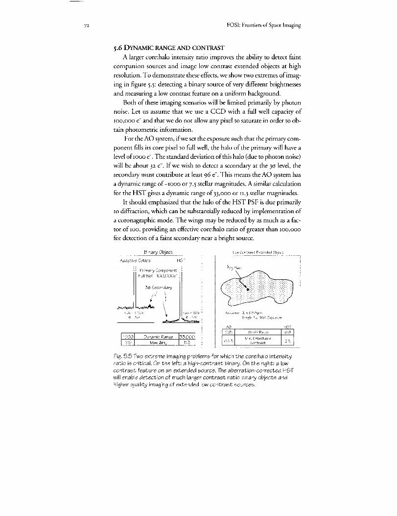
72 FOSI: Frontiers of Space imaging
5.6 DYNAMIC RANGE AND CONTRAST
A larger core:halo intensity ratio improves the ability to detect faint
companion sources and image low contrast extended objects at high
resolution. To demonstrate these effects, we show two extremes of imag-
ing in figure 5.5: detecting a binary source of very different brighmesses
and measuring a low contrast feature on a uniform background.
Both of these imaging scenarios will be limited primarily by photon
noise. Let us assume that we use a CCD with a full well capacity of
Ioo,ooo e- and that we do not allow any pixel to saturate in order to ob-
tain photometric information.
For the AO system, if we set the exposure such that the primary com-
ponent fills its core pixel to full well, the halo of the primary will have a
level ofIooo e-. The standard deviation of this halo (due to photon noise)
will be about 32 e-. If we wish to detect a secondary at the 3(s level, the
secondary must contribute at least 96 e-. This means the AO system has
a dynamic range of-Iooo or 7.5 stellar magnitudes. A similar calculation
for the HST gives a dynamic range of 33,ooo or I1.3 stellar magnitudes.
It should emphasized that the halo of the HST PSF is due primarily
to diffraction, which can be substantially reduced by implementation of
a coronagraphic mode. The wings may be reduced by as much as a fac-
tor of IOO, providing an effective core:halo ratio of greater than Ioo,ooo
for detection of a faint secondary near a bright source.
Binary Object
Adaptive Optics
:: Primary Component
Full Well 100,000e-
3_ Secondary
,(Hal,) h3Ol)e \
Ic_ 32e
HST
Low Contrast Extended Object
iiiil;iiiiDi
Assume: X : 0.55UrnSingle Full Well Exposure
AO
0,25
6.5 %
Strehl Ratio
1000 Dynamic Ranqe 3,0001 i Min Detectabletl _ I Contrast
7,5 Max Am v !
Fig. 5.5 Two extreme imaging problems for which the core;halo intensityratio is critical. On the left: a high-contrast binary. On the right: a lowcontrast feature on an extended source. The aberration-corrected HST
will enable detection of much larger contrast ratio binary objects andhigher quality imaging of extended low contrast sources.
HST

5. Adaptive Optics & HST 'Uniqueness Space' 73
The second imaging scenario involves detecting low contrast features
on an extended object. Here, too, sensitivity is critically dependent on
the core:halo ratio. Using Strehl ratios ofo.25 for AO and o.8 for HST,
we find that a uniform extended disk will have 3csphoton noise of 6.5%
of the mean intensity of the disk for AO imaging whereas the HST will
be able to be able to make a 3csdetection for intensity variation of z%.
5.7 PSF STABILITY
The uniqueness space of HST is further defined by the spatial and
temporal stability of the PSF.
The FOV limitation of AO is well known. Possibly a set of imagery
could be patched together to obtain a larger FOV. This approach has
not been explored and would be difficult for objects that change rapidly,
such as planets in our Solar System. (see section 1.3.I ) Faint large field
objects that require long exposures would also be difficult for AO. The
relative fields of view of ground-based AO and an axial bay HST AC are
shown in figure 5.6. Note that isoplanatism is best preserved by an ad-
vanced camera that uses non-vignetting relay optics.
The ground-based AO PSF will exhibit a time-variable halo of light,
due to the remnant seeing disk after correcting the lower spatial and
temporal frequencies of the atmospheric distortion.
200
tt
2 15o<
% _oo
so
Unvlgnetted HST AC
Groun_.Base_i Adaptive Optics0.5 1.0 l,b 2 0
Wavelength (pm)
Figure 5.6. The field of view over which diffraction-limited image quality isavailable. Comparison of HST and ground-based AO. One of the best
qualities of HST imagery will be the wide field over which high qualityimaging and photometry can be obtained.
2.5
74 FOSI: Frontiers of Space hnaging
An issue which has not been discussed much in the AO literature are
limitations to the length of AO exposures. The AO systems we are fa-
miliar with have difficulty maintaining lock, and the showpiece AO im-
agery often are IO msec exposures during which the system was "locked
in". We expect significant strides to be made in temporal stability of AO
systems, but establishing the capability to routinely take multi-hour ex-
posures may prove to be a tough task.
5.8 CONCLUSIONS
We expect that ground-based AO will make significant technical
strides during the I99o's. The advancements should include develop-
ment of reliable lasers for generation of sodium layer reference stars, very
low noise wave-front sensor cameras, large degree of freedom
deformable mirrors at lower expense and special purpose computers to
run the AO systems.
The level of funding and diversity of funding sources appears to be
adequate to accomplish the goal of wave-front compensation in the IR.
However, due to the limits on funding levels, the astronomical commu-
nity does not plan to pursue high quality correction for _.< 60oo a.
Ground-based AO will achieve higher resolution than HST in the
visible and near IR, due to diffraction-limited performance with the
larger apertures of ground-based telescopes. HST will provide a much
better core: halo ratio than AO, which will be limited in quality due to
the residual halo from lack of full compensation. The AO halo, which
will be significant in the visible, limits the dynamic range of imagery and
the detection of low contrast features on an extended object.
HST will provide a much larger FOV than ground-based AO: 20o
arcsec for the HST AC in an axial bay, compared with 5arcsec in the vis-
ible and IO to 25 arcsec in the IR for AO. Thus, wide field photometry
and wide field imaging of faint sources will best be done with the HST.
Other difficulties of AO, such as the tilt determination problem of
laser reference stars and the long term stability of the lock of an AO sys-
tem, may lead to an advantage of HST in terms of sky coverage and
magnitude limit.
All of these performance projections when combined with the UV
capability of HST, lead us to conclude that HST will have a unique por-
tion of parameter space within which the advanced camera can pursue
unequalled astronomical research.
_.Ag_ptive Optics & HS"T 'Uniqueness 8pace' 75
ACKNOWLEDGMENTS
James Beletic was the lead author of chapter 5.
We wish to acknowledge and thank those who took the time to make
thoughtful and insightfifl responses to the AO survey: Roger Angel,
Horace Babcock, Jacques Beckers, Steven Beckwith, Chris Dainty,
Robert Fugate, Brent Ellerbrock, Edward Kibblewhite, Tadashi
Nakajima, Malcolm Northcott, Ronald Parenti, Retie Racine, Bruce
Sams, I)avid Sandlcr, Donald McCarthy, Laird Thonlpson, and Peter
Wizinowich. The survcy responses were critical to the validity of thisdocu rllent.
Mark Colavita and Mike Shao wrote an excellent white paper for the panel,
as did Chris Burrows and Pierre Bely. Richard Goody gave us some
valuable mid-course guidance during our synthesis process.
REFERENCES
Beckers, J.M. 0993)- "Adaptive optics for astronomy: principles, perfor-
mance and applications," to be published in Annual Reviews of'As-
trono_{), and Astrophysics, 3I.
Fugate, R.Q., editor (r992). Laser Guide Star Adaptive Optics P(/or/es/aop,
Proceedings I & 2, lo-J2 March I992, Albuquerque. These volumes
contain over 5o articles that prcscnt most of the latest research in this
area.
Parenti, R.P. 0992). "Adaptive optics for astronomy," The Lincoht Labora-
tory,Journal, 5, no. l, pp. 93-114. The entire issue of this journa[ is dew)ted
to adaptive optics work at MIT [.incoln I.aboratory and the interested
reader should obtain the full issue for review.

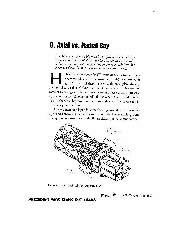
77
6. Axialvs.RadialBay
The Advanced Camera (A C) must be desigTzed fbr hzstallation into
either an axial or a radial bay. We have examined the scientijq_;technical, and logistical considerations that bear on this isszte. We
recommend that the A C be designed as an aMa/ insov4ment.
H ubble Space Telescope (HST) contains five instrument baysto accommodate scientific instruments (Sis), as illustrated infigure 6.i. Four of theses bays view the focal plane directly
and are called 'axial bays'. One instrument bay--the 'radial bay'--is lo-
cated at right angles to the telescope beam and receives the beam via a
45° pickoff mirror. Whether to build the Advanced Camera (AC) for an
axial or the radial bay position is a decision that must be made early in
the development process.
A new camera developed for either bay type would benefit from de-
signs and hardware inherited from previous Sis. For example, ground
test equipment exists to test and Gdibrate either option. Appropriate car-
• i/f
Fbjure 6.1. Axial and radial instrument bays
PAGE /7_.. INTENTIONALI.'VBLARR
PRECEDING PAGE BLANK NOT FI,LMP.D
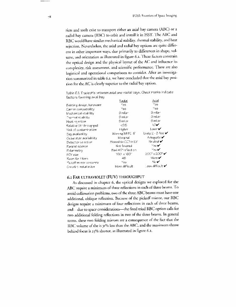
78 FOSI: Frontiers of Spacc Imaging
tiers and tools exist to transport either an axial bay camera (ABC) or a
radial bay camera (RBC) to orbit and install it in HST. The ABC and
RBC would have similar mechanical stability, thermal stability, and heat
rejection. Nevertheless, the axial and radial bay options are quite differ-
ent in other important ways, due primarily to differences in shape, vol-
ume, and orientation as illustrated in figure 6.2. These factors constrain
the optical design and the physical layout of the AC and influence its
complexity, risk assessment, and scientific performance. There are also
logistical and operational comparisons to consider. After an investiga-
tion summarized in table 6a, we have concluded that the axial bay posi-
tion for the AC is dearly superior to the radial bay option.
Table 6.1. Tradeoffs between axial and radial bays. Check marks indicate
factors favoring a×iai bay.Radial A×ia!
Existing design, hardware Yes Yes
Carrier compatibility Yes YesMechanical stability Similar Similar
Thermal stability Similar SimilarHeat rejection Similar Similar
Relative UV throughput <0.5 1.Or'Risk of contamination Higher Lower I/Bay availability Working WFPC II? Likely 2 - 3 free e¢
Guide star availability Marginal Adequate v'Detector selection 5iased to CCD in UV Neutral _#Parallel science Not favored Yes v'
Polarimetry Bad 45 ° reflection Yes e¢FOV size 160" x 160" 200" x 200"
Room for filters 48 More V'Pickoff mirror concerns Yes No V'
On-orbit installation More difficult Less difficult I/
6.I FAR ULTRAVIOLET (FUV) THROUGHPUT
As discussed in chapter 6, the optical designs we explored for the
ABC require a minimum of three reflections in each of three beams. To
avoid collimation problems, two of the three ABC beams must have one
additional, oblique reflection. Because of the pickoff mirror, our RBC
designs require a minimum of four reflections in each of three beams,
and--due to space considerations--the fixed triad RBC option calls for
two additional folding reflections in two of the three beams. In general
terms, these two folding mirrors are a consequence of the fact that the
RBC volume of the is 3I% less than the ABC, and the maximum throw
behind focus is 25% shorter, as illustrated in figure 6.z.
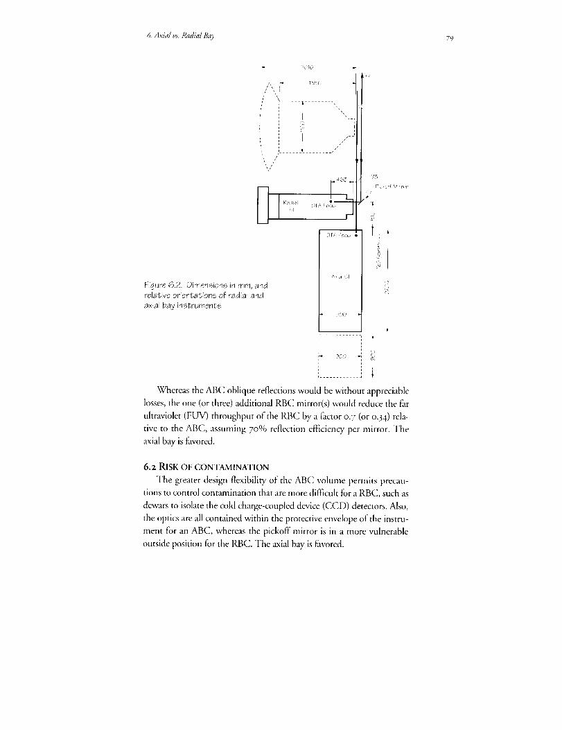
6. Axl}d l,s.Radial I_O, 79
Figure 6.2. Dimensions in mm, andrelative orientations of radial and
a×iar bay instruments
I '
jJJ
' IJr
i
[ i I
/
463L_ _
,:} T/, F ;{i J,
900
p
173
Picko_ Mir rot ¸
i
.!
,Ti
' i........ J
Whereas the ABC oblique reflections would be without appreciable
losses, the one (or three) additional RBC mirror(s) would reduce the fhr
ultraviolet (FUV) throughput of the RBC by a l_actor 0.7 (or o.34) rela-
tive to the ABC, assuming 7o% reflection efficiency per mirror. The
_i,"d bay is favored.
6.z RISK OF CONTAMINATION
The greater design flexibility of the ABC volume permits precau-
tions to control contamination that are more diflqcult for a RBC, such as
dewars to isolate the cold charge-coupled device (CCD) detectors. Also,
the optics are all contained within the protective envelope of the instru-
ment for an ABC, whereas the pickoff mirror is in a more vulnerable
outside position for the RBC. The axial bay is favored.
8o FOSI:Frontiersof Space Imaging
6.3 BAY AVAILABIHTY
Because one SI must be removed to make a place for the AC, the ex-
pected status of the on-board Sis around the year 2ooo is an important
consideration, as it would be unfortunate to replace a functioning, pro-
ductive instrument. As discussed in chapter 2, the Faint Object Camera
(FOC) will be will be far beyond its expected lifetime and has a low
probability of useful operation at the time in question---due mostly to
its high-voltage detectors. Also, after the second servicing mission, the
FOC will be the only SI still dependent on the Corrective Optics Space
Telescope Axial Replacement (COSTAR) for its optical correction.
Depending on the date of the AC installation, another axial SI--the
Near Infrared Camera (NICMOS)--might be due for change out. The
NICMOS detector will be cooled by a cryogen, which will be depleted
with time and operations on orbit. The lifetime of the cryogen will be 3
to 5 years depending on the schedule of use. Thus, the opportunity may
exist to replace the NICMOS with the AC, return the NICMOS to the
ground, replenish the cryogen, and re-fly the NICMOS. In this instance,
the NICMOS would provide a very low cost instrument for the next service
mission.
The second Wide Field Planetary Camera (WFPC II) will occupy
the radial instrument bay when the AC is installed, kVc'hileit will be be-
yond its design life, the WFPC II contains no consumable materials and
employs low-voltage solid state detectors. For these reasons, it is likely
that the 9ffFPC II will be at least partially operational in the post-zooo
period.
Thus, at least two and perhaps three of the four axial bays will likely
contain inoperative Sis at the time the AC is installed, whereas the one
radial bay will likely contain a working WFPC II. If the radial bay is
chosen for the AC, the almost certain result would be just one opera-
tional camera on HST. On the other hand, selecting a likely-available
axial bay would increase the probability of two functional cameras. The
axial bay is favored.
6. 4 GUIDE STAR AVAILABIHTY
As discussed in section 4.2, more guide stars are available to an axial
SI than to a radial SI due to increased area of the sky swept out by the
FGS field of view (FOV) as the spacecraft rolls. AS shown in table 4.2, an
estimated 25% of mid-galactic latitude targets would be unavailable to

6.Axial vs. Radial Bay 8r
the AC installed in a radial bay, a loss that increases to 45% at high lati-
tudes. The corresponding losses are I% and 5% for the AC in an axial
bay, and hence the axial bay is favored.
6. 5 DETECTOR SELECTION AND PARALLEL SCIENCE
Three of the four camera designs we have explored have independent
detectors for each beam, and in principle these detectors can operate si-
multaneously to provide a parallel science capability. The exception, the
RBC carousel option, requires one detector, which would necessarily be
a CCD to satisfy both long- and short-wavelength requirements. Select-
ing the RBC carousel option would resolve the issue of the FUV detec-
tor not on the basis of performance but of versatility. Of the two RBC
options, the carousel design is somewhat superior due to higher UV
throughput. Therefore, because it better assures that detector selection
will be based on merit and that parallel science operations will be fea-
sible, the axial bay is favored
6.6 POIARIMETRY
The large angle of the pickoffmirror eliminates the possibility ofpo-
larimetry with the RBC. The axial bay is favored.
Vi__ Axial FieldOSViewRa_ial Fieldof
/ ,,\ FGS 2 /_/_.._imes Larger
v2
\
_ cc
I IO0 mm I
101I
Figure 6.3.configuration after 1997 servicing mission.
\
//
instrument FOVs as projected onto the sky. Expected

82 FOS[: Frontiers of Space Imaging
6. 7 FOV SIZE
The maximum RBC FOV is about 16o x 16o arcsec to avoid vignett-
ing the FOVs of the axial Sis. As shown in figure 6.3, the axial bays have
a three times larger area available to accommodate larger FOVs. As dis-
cussed in chapter ii, ABC optical designs can achieve full correction of
spherical aberration and diffraction-limited performance over at least
2oo x 2oo arcsec FOVs. The axial bay is favored.
6.8 ROOM FOR FILTERS
The WFPC II has a total of 48 filters, limited mainly by the space
constraints of the radial bay. The larger volume of the axial bay increases
the space available for the filter complement, perhaps by as much as
5o%. The axial bay is favored.
6. 9 PICKOFF MIRROR CONCERNS.
The RBC's pickoffmirror appears to be an unavoidable single point
of failure, located as it is in a vulnerable, extended position. It appears to
be both at physical risk and susceptible to contamination, as discussed in
section 6.2. Also, the pickoff arm may have reduced dynamic stability:
its position must be stable to about i micron to avoid detectable image
degradation. The axi,-d bay is Favored.
6.io ON-ORBIT INSTALLATION
The delicate light seal of the RBC radiator may result in a more diffi-
cult on-orbit installation as compared with the ABC, which is within the
light-tight aft shroud. The axial bay is favored.
ACKNOWLEDGEMENT
James Crocker was the lead author of chapter 6.
7. Samplingthe Image
What image sampling strategy is appropriateJbr the Advanced Cam-
era (AC)? The ability to critically (Nyquist) sample the image is re-
quired at all wavelengths. 7his may be accomplished either ky su_-
ciently fine pixelation in the detectors or by substepping." moving the
telescope slightly and taking another exposure. Substepping may berequired in the AC's wide-fieM mode.
he choice of how finely to sample the image produced by theOptical Telescope Assembly (OTA) and Advanced Camera
(AC) optics has profound effects on the instrument design.
That is, the process of decision making inw31ves technical compromises
depending on the characteristics of the detector(s) and the physical con-
straints imposed by the spacecraft. Here we explore the sampling re-
quirements imposed by the scientifc case for the AC to see how these
can be achieved given our projections of optical and detector perfor-
mance. The expectation is that the choice of sampling depcnds critically
on the parameters that are to be estimated from the data and on the sig-
nal-to-noise ratio attained by the observations. The availabilit T of suit-
able image processing tools also bears on our degree of confidence in dif-
ferent approaches. It is desirable to search for a strategy that can, by
suitable choice from an array of available observation modes, achieve a
wide range of goals in an optimal manner.
It is important in the following discu_sion to distinguish clearly between
the 'pixel size'--which is a characteristic of the detector and camera focal
ratio--and the 'sampling' which c_m be determined by multiple expo-
sures with different pointings on the sky. A space-borne caunera with cur-
rent detectors, can achieve significant advantages from 'interleaved sarn-
piing' (sub-stepping) strategies coupled with suitable image combination
algorithms.
We first sketch out in general terms the impacts of the sampling
choice and show that some of these are substantially different with dif-

84 FOSI: Frontiersof Space Imaging
ferent types of detector. The discussion is based on critical (Nyquist)
sampling of the Airy function for a circular aperture. The necessity for
sub- and super-Nyquist sampling is investigated using model calcula-
tions and simulations based on realistic estimates of camera and detector
parameters. The experience of restoring the currently aberrated images is
relevant since the aberrated point spread function (PSF) still shows char-
acteristics of diffraction-limited performance in the core. Finally, we give
some recommendations for the camera design based on these consider-
ations, including suggestions for those parameters that need to be well
measured and understood before final design decisions are made.
7.I GENERAL IMPLICATIONS
The set of closely linked characteristics that are affected by or will de-
termine the image sampling are sketched in figure 7.t. As a reference for
the discussion, figure 7.2 gives a geometrical overview of the sampling pa-
rameters on which are marked the first and second generation of Hubble
Space Telescope (HST) imaging instruments expected to be in operation
after the I997 servicing mission (see chapter 2). The lower part of the fig-
ure gives the locus for critical (Nyquist) sampling by a detector array as a
function of wavelength. We have used a critical interval of half the dis-
tance to the first minimum of the Airy pattern for a circular aperture, o.6I
x/d, where d is the diameter of the aperture. Since sky background and
Cosmic Ray
Discrimination
Readout Noise
Sky Noise
Dark Current
Data Volume
Telemetry Rates
Count Rate
(brightness)limitation
Physical Pi×el Size
Data Compression
f ratio
Field of View
Dynamic Range
Figure 7.1. Some of the implications of the choice of how finely to samplethe image.

7. Sampling the bnage
240
! 80
8
60
"_ 50©
£
:_ 1000
1500
Figure 7.2. The relationship between wavelen6th for critical (Nyquist)
sampling and camera field of view for detectors with a set of different
pixel array dimensions recording the image without sub-stepping. The
projected set of post-1997 HST imaging instruments is marked alongwith the 'fiducial' camera discussed in the text and described in table 1.
The FOV limit imposed by the pickoff mirror for a radial camera is shown.
The lines (with ,) in the lower panel show the loci where sRy equals readoutnoise for a CCD detector working in the current WFPC wide filters
(F336W, 439W, 555W, 622W, 791W) with readout noise from 1 to 30 e .
detector noise will, in practice, limit the size of the pixels, we show in fig-
ure 7.2 some loci on which readout noise of a Charged Coupled Device
(CCD) equals sky noise for some broad-baald filters. This gives a relatively
crude picture of the very limited regimes---broad-band imaging near the
peak of the detector spectral sensitivity--in which a CCD detector can
be used effectively with critically sampling pixels and suggests strongly that
we have to search for alternative strategies.
Figure 7.3 shows the output focal ratio required to critically sample
the image with the basic pixel array as a function of wavelength. Curves
are plotted for four different physical pixel sizes from 7-5_rn (the mini-
mum size expected from available technologies) to 25_tm. The posH997
instruments have pixels of4o _ Near-Infrared Camera (NICMOS, all
85

_6 FOSh Frontiers of Space Imaging
1000 ...................................... ,.....................
qb
c_
1oo
10, -----a_
.... i .... | .... iO 500 1000 1500
Wavelength (rim)
Figure 7.3. The required camera output focal ratio to achieve criticalsampling for a set of four physical pixel sizes from 7,5 to 25 lain,
cameras), 25 _ Faint Object Camera (FOC), zI _rn Space Telescope
Imaging Spectrograph (STIS optical) and 15 _m Wide Field Planetary
Camera GYc'FPC II, STIS UV).
The simultaneous desire for wide field of view and appropriately fine
sampling leads to very large data volumes, especially for the shorter
wavelengths. This carries immediate implications for the type of on-
board computing needed in order to overcome the limited spacecraft
system telemetry rate of_ Mbit/sec (see chapter to). To put these con-
cerns into perspective, we consider a 'fiducial' camera/detector system
with a focal ratio of 2o and a detector with an array of 4o96 x 4o96
Io _n pixels. Table 7.I shows the characteristics of such a device which
would critically sample only in the near-infrared.
Table7.1.A fiducial camera/detector to
Pixel pitch 10Detector size 41
f/ratio 20Pixel 43
FOV 176
2.94
number of pixels
pixets per row & column
data volume (2 byte/pix)
1 dumptime at megabit/sec50 kHz read time
illustrate some basic quantities.
urnmm
mas
arcsec
arcmin
1.68 x t07
4096
32 megabytes4.4 min
5.6 min

Z Sampling the Image 87
7.2 DETECTOR SPECIFIC IMPLICATIONS
Further detailed implications depend on the nature of the detector
operation and we distinguish two basic types for discussion in turn. (See
chapter 8.)
7.2.i INTEGRATING DETECTOR (CCD)
CCDs can currently be fabricated with physical pixel sizes as small as
7.5 _m although these have full-well capacities limited to around
25,ooo e-. The capacity increases approximately with the pixel area and
so a balance between the achievable dynamic range in a single exposure
and the optical relay magnification will have to be achieved.
It may not always be desirable to operate this type of detector at full
resolution because of the effect of readout noise or data-rate limitations.
These parameters are coupled by the need to read the detector relatively
slowly for the best noise performance (50 kHz for I [o 2. e- rms noise).
While pixels can be binned on chip to achieve greater surface brighmess
sensitivity, there is still clearly a field of view (FOV) penalty incurred
when the pixels have a small angular size.
An important issue for these detectors is the very high rate of cosmic
ray induced charge generation. Fine sampling of the PSF in a single expo-
sure allows for considerably easier discrimination of such events from real
image features. If on-board cosmic ray cleaning is considered, full sam-
piing by the pixel array would be an advantage.
At the long focal ratios needed for a space-based camera and typical
detector sizes, the thermally generated dark current in a CCD can be-
come a significant source of noise compared with the sky and readout
contributions. Care has to be taken, therefore, to reduce this to an ac-
ceptable level by adjustment of tile operating temperature and/or keep-
ing the physical area of the resolution element projected onto the detec-
tor sufficiently small. The balance between the various noise sources for
the current generation of CCD detectors used in a space-based camera is
discussed in the appendix. There, we make a specific comparison be-
tween a single, one-orbit observation made with a critically sampling ar-
ray in the V-band with four, half-pixel stepped sub-images taken at half
the focal ratio with the same detector. It is this example which is illus-
trated in the simulation shown in figure 7-4.

88 FOSI:FrontiersofSpacehnaging
(a)
® @ @
(b) (c)
Figure 7.4. Three sampling/pixel size scenariosappropriate to theexamples discussed in theappendix. The schematicstellar image is scaled to
a 22 mas grid spacing inthe V-band. (a) small
(22 mas) pixels, nointerleaving. (b) 44 mas
pixels, 2 sub-stepsdisplaced along a diagonal.(c) Four-fold interleavimgof 44 mas pixels by onegrid-spacing.
7.2.z PHOTON COUNTING DETECTOR
The photon counting detectors do not generally suffer a readout
noise and so a fine image pixelation does not carry a signal/noise penalty
with it. The most severe constraint comes from the total number ofpix-
els since the array has to be read faster than the photon arrival rate. The
details of this saturation depend on the particular technology and can
result in either a limited rate per pixel or a limited rate integrated over
the whole array. In the former case, there is clearly an advantage in a
high magnification since this will reduce the count rate per pixel for a
given source. This means that the best performance in terms of dynamic
range, astrometric precision and image resolution can be obtained with
an array which critically samples, or even oversamples the image.
7-3 A WIDE-FIELD CHANNEL
A wide-field channel working in the optical/near infrared bands will
almost certainly use a CCD detector. The noise characteristic of'such a
device--dark current, susceptibility to cosmic rays, readout noise--will
determine the optimum strategy for a particular kind of observation.
The range of application for this channel will, of course, be very wide--
from spatial resolution of bright, complex structures to the detection of

7. Sampling :he [mage X9
very faint extended objects against the sky background. Therein lies the
difficulty in choosing design parameters. The goal will be a solution
which is flexible in allowing both of these extremes while maintaining
the widest possible field of view.
High astrometric precision and the resolution of structure at high sin
demands critical sampling. Photometric performance, we will show, is
better--at least for faint sources--with pixels which themselves
undersample the image. The limit in this case is likely to be the knowl-
edge of the pixel-scale variations in the flat-field response. For a given
detector pixel grid the spatial sampling can be improved by combining
multiple 'interlaced' (or 'interleaved' or 'sub-stepped') frames (Adorf
I989, I99O). The method of interlaced frames is very flexible since it al-
lows different sampling geometries to be realized simply by observa-
tional design. Doublets of frames, shifted by half a pixel-diagonal with
respect to each other, increase the spatial sampling by a factor of 2 in
both the principal detector directions. Quartets of subframes can be
combined either in a square grid or, perhaps more interestingly, in a hex-
agonal grid resulting in an improved spatial sampling of the isotropic
optical PSF generated by a circular aperture. The scenario described in
the appendix considers the case of broad-band V imaging of point
sources using a total exposure time of one orbit (2,4oo s). It compares
the photometric and astrometric precision which can be obtained in
three different modes:
i. a single exposure with critically sampling pixels (figure 7.4a)
2. a single exposure with pixels which two-times undersample
3. four I/2 pixel interleaved exposures with the larger pixels--
identical samplingto case I (figure 7.4b).
Cases 2 and 3 result, of course, in an image field which is four times
as large as that in case ].
Calculations of the minimum-variance (Cramer-Rao) bound for
these cases (Adorf private communication, see also King _983) show the
variation of the photometric and astrometric information content in the
observation of a point source with sky and detector background in these
three and other cases. The realization of this lower botmd in the data
analysis demands an appropriate combination of the interleaved sub-im-
ages. With the simple interleaving of the sub-images onto a finer grid,
the resolution is, of course, determined by the convolution of the optical
PSF with the large pixel response function. A conservative application of
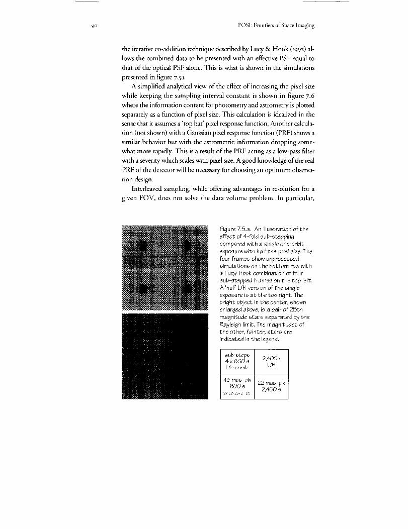
90 FOSI:FrontiersofSpace Imaging
the iterative co-addition technique described by Lucy & Hook 099z) al-
lows the combined data to be presented with an effective PSF equal to
that of the optical PSF alone. This is what is shown in the simulations
presented in figure 7.5a.
A simplified analytical view of the effect of increasing the pixel size
while keeping the sampling interval constant is shown in figure 7.6
where the information content for photometry and astrometry is plotted
separately as a function of pixel size. This calculation is idealized in the
sense that it assumes a 'top hat' pixel response function. Another calcula-
tion (not shown) with a Gaussian pixel response function (PRF) shows a
similar behavior but with the astrometric information dropping some-
what more rapidly. This is a result of the PRF acting as a low-pass filter
with a severity which scales with pixel size. A good knowledge of the real
PRF of the detector will be necessary for choosing an optimum observa-
tion design.
Interleaved sampling, while offering advantages in resolution for a
given FOV, does not solve the data volume problem. In particular,
Figure 7.5.a. An illustration of theeffect of 4-fold sub-steppingcompared with a single one-orbit
exposure with half the pixel size. Thefour frames show unprocessedsimulations on the bottom row with
a Lucy-Hook combination of four
sub-stepped frames on the top left.A 'null' L/H version of the single
exposure is at the top right. Thebright object in the center, shown
enlarged above, is a pair of 25thmagnitude stars separated by theRayleigh limit. The magnitudes ofthe other, fainter, stars are
indicated in the legend.
sub-steps 2,400s4 x 600 s
L/HL/H comb.
43 mas_pix 22 mas_pix600 s2,400 s
2'728 25x2 2!9
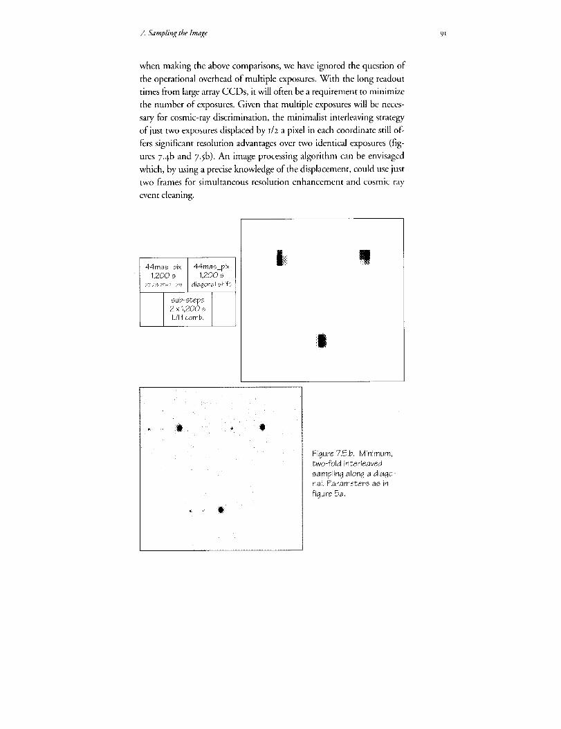
7. Sampling the Image 91
when making the above comparisons, we have ignored the question of
the operational overhead of multiple exposures. With the long readout
times from large array CCDs, it will often be a requirement to minimize
the number of exposures. Given that multiple exposures will be neces-
sary for cosmic-ray discrimination, the minimalist interleaving strategy
of just two exposures displaced by I/z a pixel in each coordinate still of-
fers significant resolution advantages over two identical exposures (fig-
ures 7.4b and 7.5b). An image processing algorithm can be envisaged
which, by using a precise knowledge of the displacement, could use just
two frames for simultaneous resolution enhancement and cosmic ray
event cleaning.
44mas_pix1,200 s
27 28 25×2 Z9
44mas_pix1,200 s
diagonal shift
sub-steps2 × _,200 sL/H comb.
Q_ • Q
Figure 7.5.b. Minimum,two-fold interleaved
sampling along a diago-nal. Parameters as in
figure 5a.
• •
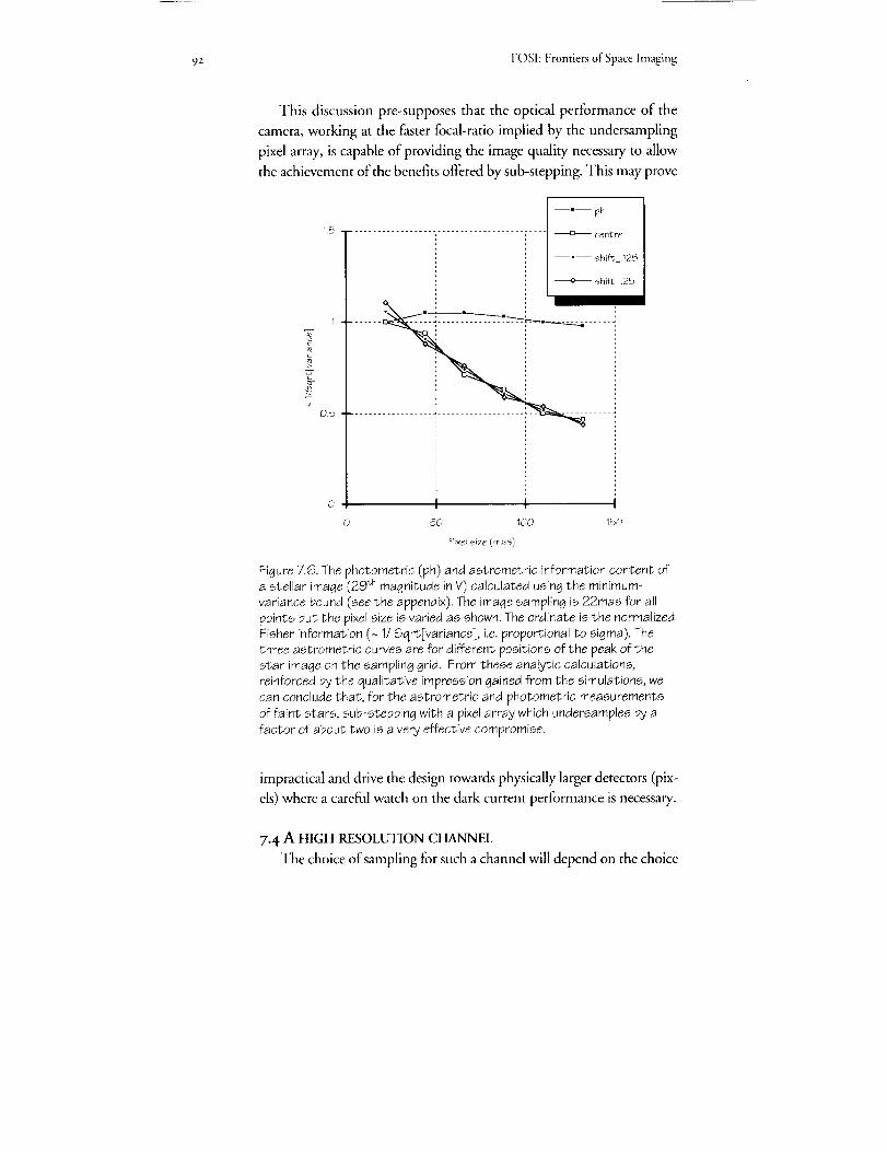
92 FOSI: Frontiers of Space Imaging
This discussion pre-supposes that the optical performance of the
camera, working at the faster focal-ratio implied by the undersampling
pixel array, is capable of providing the image quality necessary to allow
the achievement of the benefits offered by sub-stepping. This may prove
T
1.,5
0.5
0
©
--'-- ph
................... : ........................ _ centre
--.-- shift .125
shift .25
i I
5_) 100 150
Pix¢l size (mas)
Figure 7.6. The photometric (ph) and astrometric information content ofa stellar image (29 th magnitude in V) calculated using the minimum-
variance bound (see the appendix). The image sampling is 22mas for all
points but the pixel size is varied as shown. The ordinate is the normalizedFisher information (~ 1/Sqrt[variance], i.e. proportional to sigma). The
three astrometric curves are for different positions of the peak of the
star image on the sampling grid. From these analytic calculations,
reinforced by the qualitative impression gained from the simulations, we
can conclude that, for the astrometric and photometric measurements
of faint stars, sub-stepping with a pixel array which undersamples by a
factor of about two is a very effective compromise.
impractical and drive the design towards physically larger detectors (pix-
els) where a careful watch on the dark current performance is necessary.
7.4 A HIGH RESOLUTION CHANNEL
The choice of sampling for such a channel will depend on the choice

7. Sampling the hnage 93
of detector. For photon counting devices, as we have already pointed out,
there are advantages in having pixels which critically or super-sample the
PSF. For integrating detectors on the other hand, it is clear that the pixel
readout will be the dominant noise source for Faint objects since such a
device will not see the sky background even in broad-band filters. Criti-
cal sampling in this case can only be recommended to satisfy scientific
requirements other than reaching the faintest objects. Apart from straight-
forward high-resolution studies of bright objects, the application of
coronographic techniques and/or the use ofapodizers may demand that
the image is sampled directly with a fine grid. It is clear that telescope
repointing cannot be used for sub-stepping the image in this case ,although
an internal tip-tilt mirror system could, possibly, be devised.
7.5 CALIBRATION AND IMAGE PROCESSING REQUIREMENTS
The existence and maintenance of good calibration isessential for high
quality data analysis. This rather obvious statement includes the need for
a detailed (stochastic) model of both the deterministic and noise charac-
teristics of the instrument. Optimum estimators can then be constructed
for a particular measurement task. Such a model has been derived for the
WFPC and isdescribed by Snyder, Hammoud & White (I99Z).
In practice, with a high dynamic range detector, uncertainties in flat-
fielding and knowledge of the PSF can become the limiting factor in the
accuracy of measurement.
7.6 THE PSF
Photometric and astrometric experience with ground-based observa-
tions has generally been based on simple 'unimodal' PSFs with a nearly
Gaussian shape (e.g. King-profile, Moffat-profite etc.) produced by at-
mospheric distortions. These PSFs, characterized by a sharp central peak
and featureless wings, are usually sufficiently well sampled that knowl-
edge of the exact shape of the pixel and its sensitivity response function is
not important. In particular, there is practically no positional informa-
tion in the outer PSF-wings.
The nearly diffraction-limited PSF of a space telescope has quite dill
ferent characteristics. Apart from the central peak there are diffraction
rings, into which the flux of the wings is concentrated. Thus more pho-
tometric/flux information is contained in the wings of a diffraction-lim-
ited PSF than in that of a structureless PSF. For a centrally obscured ap-

94 FOSI: Frontiers of Space Imaging
erture like HST, more than a quarter of the photometric, and a signifi-
cant fraction of the astrometric, information is carried outside the PSF
core.
When the PSF is near-critically sampled the exact shape and re-
sponse function of the pixds and the geometry of the sampling grid be-
come important. The available astrometric information resides in the
slopes of the effective PSF. Assuming an ideaJ (hat-shaped) PRF, appro-
priate for a thinned CCD-detector, each pixel contributes astrometric
information (in the appendix we use the 'Fisher' information from sta-
tistics-the inverse of the variance) proportional to the square of the dif-
ference of the optical PSF value at its boundaries (Adorf, priv. comm.).
Thus two pixels contribute relatively more astrometric information
when a mode of the PSF coincides with their mutual boundaries, com-
pared with the situation when the mode coincides with one of the pixel
centres,
Thus the rings of a diffraction-limited PSF contribute a significant
fraction of the overaJl astrometric information, particularly since their
modes cross pixel boundaries even when the core is centered on a pixd.
For bright objects the diffraction spikes due to the spiders in the optical
path may hold considerable additional spatial information, particularly
when their modes coincide with pixel boundaries. Only a full zD-calcu-
lation of the relevant minimum variance bound can darify the quantita-
tive aspects of these considerations.
The spherical aberration corrected OTA will deliver images which
are close to being diffraction limited in the optical. In the UV, the PSF
will contain more structure with some fixed 'speckles' around a sharp
core. The image restoration techniques, whose accelerated development
was necessary to deal with spherical aberration, will remain fully appli-
cable to the corrected images. This implies that a high precision knowl-
edge of the PSF will be essential.
Currently, HST PSFs are being derived from a combination of mea-
surement and modelling. For the treatment of high dynamic range data,
observed PSFs of sufficient quality are very hard to obtain and even the
best computed functions are inadequate. In the case of the WFPC, the
situation is exacerbated by the strong spatial dependence introduced by
asymmetric pupil shadowing from the Cassegrain repeater secondary mirror.
The lesson we learn from this is that the PSF of a new camera needs
to be precisely known from measurement or accurately computable for

Z 5:ampling the Image 95
the appropriate conditions or, preferably, both. The modelling will al-
ways be necessary at some level, even if only to provide interpolating
functions, since the PSF needs to be known at finer sampling than the
data and the color dependence will produce object dependent results forbroad filter observations.
The spatial variation of the PSF introduces considerable computa-
tional complexity into the restoration task and the best solution would
be an optical design which minimized it. If spatial variation is unavoid-
able, it is important that we are able to compute it accurately.
Spatial distortions in the pixel array, unless well calibrated and
treated in a sophisticated way, can cause loss of resolution and undesir-
able noise correlations as a result of conventional resampling algorithms.
Such an effect is seen clearly in geometrically corrected images from the
FOC which has substantial geometric distortion arising within its elec-
tron optical components.
With the high optical magnifications needed to sample the PSF in
the far-UV, it is possible to run into difficulties with 'edge-effects'. The
sidelobes of the Airy function spread a long way from the core and re-
storing high dynamic range data can be a problem if the detector has
only a small area. This problem is seen with FOC f/96 data at the mo-
ment with the very wide aberrated PSF.
For the ultimate resolution on high dynamic range objects to be
achieved using techniques such as 'roll-&convolution', Mueller and
Weigelt 0987) recommend pixel sizes as small as 4 to 6 mas in the far-
UV. Similar results could be achieved by an active control of the PSF,
e.g. by small focus changes, which are similarly able to move the zeroes
in the Modulation Transfer Function (MTF) of the camera. Since
changing the OTA focus as part of an observing program is undesirable
and unlikely to be allowed by the project, the ability to change the cam-
era focus internally on a regular and highly repeatable basis could be
considered important. For well-sampled images, the limits to the resolu-
tion which can be obtained using non-linear restoration algorithms have
been derived as a function of signal-to-noise ratio by Lucy 0992a,b).
7.7 POINTING AND TRACKING
The projected tracking performance of the HST is discussed in
chapter 4, and we make a few remarks here which are pertinent to image
processing.
96 FOSI: Frontiers of Space Imaging
An rms jitter of 3 to 4 mas will not have a profound effect on resolu-
tion, even in the far-UV. Since it is not clear, however, that this jitter will
have a Gaussian distribution and be circularly symmetric, it is important
that the data carry with them the record of the actual telescope pointing
during an observation. This can be used in the construction of the ap-
propriate PSF.
If undersampled frames are to be obtained and processed, the ability
to offset the telescope by non-integral pixel steps can be used, with sub-
sequent combination, to recover resolution. While this technique can be
used for random, non identical, pointings (Adorf I992), the ability to
specify and control sub-pixel pointings is desirable. The ability to do this
quickly and repeatedly without incurring the overhead of telescope re-
pointing, could be important for operational efficiency.
7.8 CONCLUSIONS
I. The pixel size of the detector and the frequency of the grid used to
sample the image should be considered separately since their relation-
ship to one another depends on the detector noise characteristics.
2. For high signal/noise observations, the ability to critically sample
the image is essential in order to recover and, in some cases, exceed the
resolution of the optical system.
3- Given the very wide wavelength coverage available to the camera,
this critical sampling requirement, coupled with the desire for the widest
FOV, will necessitate more than one optical magnification or channel.
4- To achieve the highest surface brightness sensitivity in the pres-
ence of detector readout noise, it will be necessary to use relatively large
pixels. This can be achieved, in the case ofa CCD, by 'noiseless' on-chip
binning techniques.
5. Sub-critical sampling may be necessary in some cases to alleviate
data volume and telemetry constraints and to achieve fast exposure re-
peats.6. The use of 'interleaved sampling' (sub-stepping) strategies offers
the prospect of obtaining a large FOV with available CCD detector ar-
rays while maintaining good astrometric precision and image resolution.
The effective and efficient use of these techniques may require that the
camera have a precise internal pointing/guiding system for producing
sub-pixd offsets. Very effective sub-frame combination algorithms al-
ready exist and can be optimized for this application.

7. SamplingtheImage 97
7. The resolution of an image in inherent in the sampling grid, The
increase in pixel size above the grid spacing by up to a factor of about
two produces only a slow loss ofastrometric/resolution information.
8. A 'minimalist' sub-stepping strategy, using just two exposures,
should be developed for simultaneous resolution recovery and cosmic
ray detection and removal.
9- Image restoration and combination techniques require an accurate
model of the deterministic and the noise characteristics of the instru-
ment. In particular, the PSF needs to be precisely measured and/or accu-
rately computable. A precise knowledge of the individual pixel response
function of the detector(s) will be necessary for devising appropriate sub-
stepping strategies.
io. A high-resolution channel, which may provide coronographic
and/or apodizing capabilities, will probably require a detector array
which critically or supercritically samples the image directly.
ii. For very high precision observations, active control of the PSF
(i.e., internal focusing) is desirable.
On this basis, we recommend:
I. The ability to critically (Nyquist) sample the image is required at all
wavelengths.
2. In the wide-field mode, it may be neither feasible nor desirable to
achieve critical sampling with the pixel array in a single exposure.
ACKNOWLEDGEMENTS
Robert Fosbury was the lead author of chapter 7. Hans-Martin Adorf,
Richard Hook, Leon Lucy, Wolfram Freudling, and Adeline Cauletcontributed.
REFERENCES
Adorf, H.-M., i989, "On the HST Wide Field and Planetary Camera
Undersampling Problem", in: ?tESO/ST-ECFDataAnalysis Workshop,Aprz989, Garching b. Miinchen, FRG, P. Grosbol, R.H. Warmels, and
F. Murtagh (eds.), European Southern Observatory, Garching b.Mtinchen, FRG, pp. 2t5-2_8.
Adorf, H.-M., I99o, "WFPC: Options for Overcoming Undersampling", in:Workshop "Errors, Bias, and Uncertainties in Astronomy", Sep z989,
Strasbourg, France, C. Jaschek and F. Murtagh (eds.), Cambridge
University Press, Cambridge, UK, pp. 71-78.

98 FOSI: Frontiers of Space Imaging
Adorf, H.-M., i99z, "HST image restoration--recent developments", in:
Science with the Hubble Space Telescope, Chia Laguna, Sardinia, z 9 Jun-
7 Jul I992, P. Benvenuti and E. Schreier (ed.), European Southern
Observatory, Garching b. Miinchen, FRG.
Cheung, K.F., Marks, R.J., II: i99o, "Imaging sampling below the Nyquist
density without aliasing", J. Opt. Soc. America A 7, No. I, 9z.
Ghiglia, D.C.: 1984, "Space-invariant deblurring given N independently
blurred images of a common object", J. Opt. Soc. America A l, No. 4,
398-4oz.
Hildebrant, J.W., Newsam, G.N.: i99o, "Subpixel Resolution by Image
Registration", IEEEE ISSPA , 59-518.
Irani, M., Peleg, S.: I99I, "Improving resolution by image registration",
CVGIP: Graph. Models Image Proc. 53, No. 3, z3I-Z39-
Kim, S.P., Bose, N.K., Valenzueta, H.M.: I99o, "Recursive Reconstruction
of High Resolution Image From Noisy Undersampled Multiframes",
lEEk" Trans. Acoust. Speech Signal Proc. ASSP-38, No. 6, loI3-Ioz 7.
King, I. J., _983. "Accuracy of Measurement of Star Images on a Pixel Array".
PASP, 95, 163.
Lucy, L.B., _99za. "Resolution limits for deconvolved images". Astronomical
Journal, in press.
Lucy, L.B., 199zb. "Statistical limits to superresolution". Astronomy &
Astrophysics, in press.
Lucy, L.B. & Hook, R.N., I99z. In: Proceedings of the ,stAnnual Conference
on Astronomical Data Analysis and Systems, Tucson, November 199I,
eds. Worrall et al., ASP Conference Series, z 5, z77.
Mueller, M. & Weigelt, G., 1987, Astron. Astrophys. t75, 31z.
Namura, Y., Naruse, H.: 1988, "Reduction of Obscuration Noise Using
Multiple Images", Pattern Analysis and Machine Intelligence IO, 2.67.
Snyder, D.L., Hammoud, A.M. & White, R.L., I993. "Image recovery from
data acquired with a charge-coupled-device camera". J. Opt. Soc.
America A, IO, p. ml 4.
Tsai, R.Y., Huang, T.S.: J984, "Muhiframe image restoration and registra-
tion", in: Advances in Computer Vision and Image Processing, JAI Press
Inc., pp. 317-339 .
Ur, H., Gross, D.: ]992, "Improved resolution from subpixel shifted pic-
tures", CVGIP: Graph. Models Image Proc. 54, No. z, 181-186.
APPENDIX
A) Simulated examples referred to in the text
This appendix outlines a quantitative comparison which has been
Z Sampling the Image 99
performed of imaging performance at different focal ratios for a CCD
detector operating in the WFPC V-band. The CCD parameters are
thought to be representative of current state-of-the-art devices: read
noise: 3 e- rms; dark current: 4.4 x IO-s e-/lamZ/s; pixel size: IO _2m; sky
brightness: z4.z mag/arcsec_; total (detector+optics) efficiency: 45%.
These parameters are used in the simulations illustrated in figure 7.5a
and b.
The comparison between a single one-orbit exposure at f/4o and 4 x
6o0 s sub-stepped exposures at f/zo illustrates the effect that a signifi-
cant dark current can have on exposures with a large f-ratio--because a
larger physical area of silicon is used to cove a resolution element. This
may not be a serious issue if the dark current can be kept to a sufficiently
low level. Narrow band observations will, of course, be more affected by
the detector noise sources and so, for photometry, larger pixels are an
advantage. The practical limit to increasing pixel size will come from
considerations ofastrometric precision, even where sub-stepping is prac-
tised. For effective astrometry, the PSF gradient must be sampled by
pixel boundaries.
For the final design of the camera, it will be important to know the
spatial response function ofa pixel in order that the 'effective PSF'--the
convolution of the optictl PSF with the pixel response function--can be
used in modelling the process of image formation.
In the simple model used for the examples, the photometric perfor-
mance has been calculated using a King profile (King I983) with a scale
factor appropriate to the V-band. 'Aperture' photometry covering 6o%
of the flux in the PSF is used in calculating the variance and the signal-
to-noise ratio. The readout noise has, for simplicity, been included inthe variance calculation as a Poisson rather than a Gaussian random vari-
able.
B) The Minimum-variance (Cramer-Rao) bound: astrometry with sub-
stepping
Many considerations including sky-coverage and flexibility speak in
favour of'large' pixels on an array that insufficiently samples the effective
point-spread function. Also, depending on detector characteristics, the
photometric precision obtainable from four combined interlaced frames
with 'big' pixels may be better than that obtainable from a single frame
with 'small' pixels exposed four times as long. The only considerations

/oo FOSI: Frontiers of Space Imaging
speaking in favour of small pixels relate to astrometry and resolution.
Calculations of the astrometric minimum variance bounds of an un-
biased estimator for the flux and position of a point source (see figure
7.6) have been carried out under the following assumptions:
I. The PSF has a King profile.
z. The spatial sampling is critical (Nyquist).
3. The pixel size (i.e., side length) is varied from the sampling
distance (z2 lam) upwards.
4. The same total exposure time is divided amongst sub-steps at
all points.
5. The quantities for the source and background counts are taken
from the example in Appendix A.
C) Combination ofundersampled multiframes--bibliography
The method of combining several individually undersampled inter-
laced ('dithered') image frames into a common high resolution image--
with or without an internal image restoration step--has been investi-
gated in recent years (Ghiglia 1984; Tsai & Hunag 1984; Namura &
Naruse 1988; Cheung & Marks 199o; Hildebrant & Newsam 199o;
Kim, Bose & Valenzuela 199o; Irani & Peleg 1991; Ur & Gross I992 ).

I01
8. Detectors
History has shown detectors are a critical and pmblenmtic aspect ofdeveloping asovnomical instrumentation. We have examined the
issue of detectors for the Advanced Camera (A C): What detectors
are appropriate? What is their current state of readiness? How can
we assure that the proper detectors will be available?
We find that for wavelengths 3000 to io, ooo ,4, current charge-
coupled device (CCD) technology can produce nearly ideal, fidly-
featured detectors for the AC However, immediate investment is
required to assure the availability of these CCDs.
For wavelengths iooo to 2ooo ,4, no satisfactory detector/filter co,n-
bination for the AC is curren& assured. To develop onepossible so-
lution, technology development is required in anti-refk, ction (AR)coatings and backside passivation to enhance the ultraviolet (UV)
performance of CCDs in the iooo to 3ooo ,4 range. Coupk'd u,ith
this, reliable Wood}filters are needed to render the CCDs blind to
red light in UV applications. To assure a viable altenmtive to UV-
sensitive CCDs, further development is required of large-fo,vnat
micro-channel plates (MCPs) and appropriate readout technolo_),for photoaathode detectors in the wavelength range iooo to 2ooo 14.
he scientific goals of the Hubble Space Telescope (HST) Ad-vanced Camera (AC) translate into detector performance re-
quirements such as pixel size and format, quantum efficiency
(QE), resolution, noise level, photometric stability,, controller electron-
ics, and data capacity for the instrument computer. The candidate sci-
ence programs for the AC--which call for detecting light over the de-
cade of wavelengths from moo to m,ooo A---will require at most two
detector technologies. These technologies are charge-coupled devices
(CCDs) and photocathode-based, photon-counting detectors. In this
chapter we discuss the current status of these detector technologies and
present our a_ssessment of the feasibility of developing them for the AC
in the time frame required.

_oz FOSI:FrontiersofSpaceImaging
8.I CHARGE-COUPLED DEVICES (CCDs)
CCDs are the imaging detector of choice for nearly all scientific in-
vestigations in the near ultraviolet/optical (NUVO) spectral regionJ CCDs
are thin silicon structures that are divided into an array ofpixels by elec-
tronic circuits on the 'ffontside' surface. When a quantum of light (a photon)
enters the silicon and is absorbed, it produces a photoelectron, which persists
until transferred to an amplifier at the edge of the CCD array by the con-
trolling electronics. As the charge is transferred, the amplifier output sig-
nal is proportional to the accumulated photoelectrons in each pixel of the
CCD array transferred in turn according to a programmed clocking se-
quence. Finally, a computer receiving the digitized amplifier output or-
ganizes the time record of the amplifier output into an array of numbers
that are proportional to the number photons absorbed in each pixel of
the array, and produces an image.
They have been used on many space missions, including the Galileo
spacecraft bound for Jupiter and the Wide Field Planetary Camera
(WFPC) launched with HST. The CCD's wide dynamic range, high
sensitivity, linearity, stability, and low noise has made it an excellent
choice for space applications. The major problems associated with
CCDs are the great difficulty of achieving high sensitivity in the ultra-
violet (UV), especially in the Iooo to 3000 A spectral region, their intrin-
sic read noise, and their high sensitivity to visible/near infrared (IR) lightwhen used for UV observations.
Most scientific quality CCDs made today have similar characteris-
tics, and their differences are due mainly to different approaches to opti-
mization on the part of the manufacturers. Photoelectrons are trans-
ferred to the output amplifiers with 0.999999 efficiency. Formats of
zo48 x zo48 pixels are standard and 4o96 x 4096 is experimental at the
current time. The maximum number of photoelectrons per pixel ('full
well capacity') is proportional to pixel area. For 7.5 x 7.5 _ pixels, the
full well capacity is about zS,ooo electrons (e-). The photometric non-
linearity is less than I%, and the spatial response is uniform to within
5%. The amplifier readout noise is z to 4 e- at operating temperatures
-60 to qoo ° C.
8.I.I FRONT ILLUMINATED CCDs
Normal, off-the-shelf CCDs are used in the front illuminated mode.
They have inferior quantum efficiency (QE) in the visible (<50%) due

_. Detectors lO 3
to reflection and absorption in the frontside electronic structures. Be-
cause light must pass through these structures that define the pixels
(composed mainly of polysilicon), most radiation of )v< 400o _ is ab-
sorbed or reflected before detection. Since the fromside is usually passi-
vated with a protective glass coating, anti-reflection (AR) coatings can-
not be applied to reduce the significant reflection loss. The refractive
index of the passivation is about I. 5, whereas that for silicon is as high ,as
seven in the near-UV. Therefore, an AR coating on the glass will im-
prove QE by only a few percent, and substantial losses will remain at the
inaccessible interfaces between the passivation glass and the polysiticon
gates, and between the gates and the underlying gate oxides.
New front illuminated CCD concepts exist that could reduce these
UV problems, as discussed below.
Phoqohors
By coating the front side ofa CCD with a phosphor, which absorbs
UV photons and re-emits them in the visible, it is possible to obtain
20% QE in the UV with a peak response of 5o% in the visible. Such de-
tectors will be used in the HST second-generation Wide Field Planetary
Camera (WFPC II). The major problems with phosphors are the pos-
sible degradation in UV efficiency due to coating changes, the risk of
condensing contaminates on the cold windows, and the low overall UV
response.
Thin polysilicon
It is ,also possible to make CCDs with thinner polysilicon than is tra-
ditionally used to decrease the absorption in the frontside structures. In
this case, the UV response with a phosphor overcoat is expected to be
25%, with a peak response in the visible of 65%.
Open-phase devices
It is also possible to produce devices with "exposed" silicon on the
frontside by adjusting the relative sizes of the pixel phases. In this case,
bare silicon can be used for some fraction of the detecting area, and the
benefits of an AR coating can be realized. Such an open-phase CCD will
also not suffer from frontside UV absorption over that fraction ofa pixel
which is bare silicon.
104 FOSI: Frontiers of Space Imaging
8.1.2 BACK-ILLUMINATED CCDs
The most efficient method of making UV sensitive CCDs is to thin
the devices to a total thickness of less than 2o _n and illuminate the de-
vice from the back side. In this case the light passes directly into the sili-
con for efficient detection. Although these devices are difficult and ex-
pensive to develop as compared with front-illuminated detectors, they
are critically important for efficient UV observations.
Since the surface of back-illuminated CCDs is silicon, an AR coating
is required, which can increase QE to nearly Ioo%. Careful control of
the surface properties can allow radiation sensitivity from X-rays to the
near-IR. Currently, Tektronix is the only domestic commercial supplier
of such devices, although Lincoln Labs at the Massachusetts Institute of
Technology (MIT) and Reticon have made thinned devices, and Stew-
ard Observatory at the University of Arizona is thi,ming devices fromvarious manufacturers.
Thinning and packaging
A concern with using existing thinned CCDs for astronomy is
mounting the devices flat in the final package. For example, the Texas
Instruments 8oo x 8oo CCDs used in the HST WFPC have peak-to-
valley non-flatness deviations up to IOO _n, which results in &focus de-
pendent on field position and therefore loss of resolution. ThinnedCCDs must be mounted in a manner that assures flatness and mechani-
cally stability.
Backside charging
Thinning CCDs leaves a large backside potential well, which is
formed by positive charge. Without corrective measures, this potential
well lowers the QE of the thinned CCD below even that of a front-illu-
minated device. The process of eliminating this effect is referred to as
'backside charging. '2 For the AC CCDs we expect backside charging
will be accomplished either by 'flash gate', 'bias gate', or ion implanta-
tion. A flash gate3 employs a very thin layer of a metal with a larger work
function than silicon deposited on p-type silicon, which causes electrons
to flow from the silicon to metal and produce a backside charge. A bias
gate employs a thin metal layer separated from the silicon by a deposited
insulating layer, effectively creating a capacitor; applying a potential to
the metal then induces a charge in the silicon. Ion implantation changes
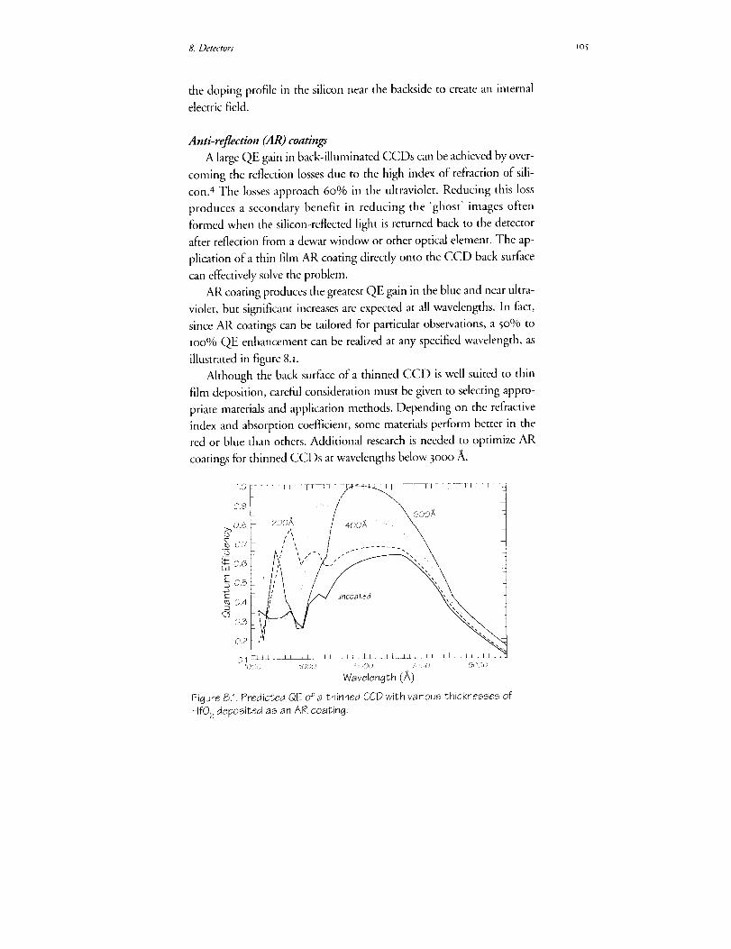
8. Detectors 1o_
the doping profile in the silicon near the backside to create an internal
electric field.
Anti-rqgection (AR) coatings
A large QE gain in back-illuminated CCDs can be achieved by over-
coming the reflection losses due to the high index of refraction of sili-
con.4 The losses approach 60% in the ultraviolet. Reducing this loss
produces a secondary benefit in reducing the 'ghost' images often
formed when the silicon-reflected light is returned back to the detector
after reflection from a dewar window or other optical element. The ap-
plication of a thin flint AR coating directly onto the CCD back surface
can effectively solve the problem.
AR coating produces the greatest QE gain in the blue and near ultra-
violet, but significant increases are expected at all wavelengths. In fact,
since AR coatings can be tailored for particular observations, a 50% to
too% QE enhancement can be realized at any specified wavelength, as
illustrated in figure 8.1.
Although the back surface of a thinned CCD is well suited to thin
film deposition, careful consideration must be given to selecting appro-
priate materials and application methods. Depending on the refractive
index and absorption coefficient, some materials perform better in the
red or blue than others. Additional research is needed to optimize AR
coatings for thinned CCDs at wavelengths below 3o00 A.
/ ">.: o.Tk ,",, I %2_ , _ / , / ",
0.6 v _. ,
0.3
0.2 L_0.1 _ l£_Jl ±XJ_L I L s_L&l _LL L _X_/ I L x _L_.i 1 I i
1_ )')!3 30,i;'0 fSi;iO( ) 70[)0 9}l)0( :
V,/avelength (£)
Figure 8.1. Predicted QE of a thinned CCD with various thicknesses of
HfO2 deposited as an AR coating.

Io6 FOSI: Frontiers of Space Imaging
8.i.3 CONTROLLER REQUIREMENTS
Major gains have been made in recent years in the performance and
operational flexibility of CCDs by the addition ofelectrica] circuits that
make the CCD highly programmable. Accessed through the instrument
computer (chapter lO), these controller capabilities can be expected to
render the AC CCDs robust, efficient, and far more capable than the
CCDs currently installed on HST.
On-chip binning
Binning allows multiple pixels to be summed together before read-
out in a noiseless manner. This can significantly reduce readout time
when full spatial resolution is not needed.
Selectabl. sub-array readout
Sub-array readout lets the observer specify a subsection of the CCD
pixels to be readout, disregarding other data on the detector. This is es-
pecially useful when data on a small object is desired.
Partial inversion/multi-pinned phase (MPP)
MPP operation allows reduced dark current at a given temperature
of operation, at the cost of reduced full well capacity.
Anti-blooming
Anti-blooming mode keeps bright objects in the imaging area from
saturating the entire image by blooming up and down columns when
the full well capacity is exceeded.
High speed erasure
High speed erasure allows flush the entire CCD in just seconds be-
fore each exposure.
Skipper clocking
If the CCD has a skipper amplifier, it can be multiply sampled, to
allow Nmultiply reads of each pixei value, decreasing the effective read
noise by _]N.
Selectable gain
Depending on the observing requirements, different observers may
desire different gains to improve dynamic range.
8. Detectors _o7
Commandable voltage settings
Commandable voltage settings would allow CCD clock voltages to
be changed in flight for device optimization.
Programmable clocking sequences
Programmable clocking would also allow the clocking wave forms to
be changed in-flight to allow device optimization and help guard against
various failure modes.
8.i. 4 MOSAICS
CCD mosaics have several possible advantages for the AC. They al-
low completely redundant detectors in case of device failure, an effec-
tively large image area can be obtained with any desired pixel size, and
they allow many amplifiers to be used for simultaneous readout for
higher effective data rates. Several groups have now produced CCD mo-
saics of up to four zo48 x zo48 pixel CCDs. If mosaics are required in
the AC, they will be straightforward to design and produce.
8,I. 5 RED LEAK
Most astronomical objects of interest emit i04 to _08 visible photons
for every far-UV (FUV) photon in the Iooo to zooo A wavelength re-
gion. Since typical FUV filters have visible transmissions of the order of
I0-3 to i0-4, FUV images would normally be hopelessly contaminated by
redqeak photons.
A limited amount of research has gone into making Wood's filters,
which use alkali metal films to block red light at frequencies below the
plasma frequency of the free electrons in the metal. Wood's filters reject
red light by factors about IO-8. In comparison, so-called 'solar-blind' Csl
photocathodes have visible light quantum efficiency of the order of I O-6,
which when combined with standard FUV filters provides visible light
rejection better than or comparable to the Wood's filter. The combina-
tion of relatively low throughput and concerns regarding their longterm
stability means that further development is probably required for
Wood's filters to compete with photocathode-based detectors for UV
observations.
8.I.6 RESEARCH REQUIRED FOR AC CCDs
The basic manufacturing processes required for CCD technology
I08 FOSI:FrontiersofSpaceimaging
arerelativelystandardforthesemiconductor industry and will hopefully
continue to be available at fabrication facilities. The areas of CCD ex-
pertise that the scientific community has been in danger of losing are
those of very low noise CCD amplifier design, techniques to obtain ex-
cellent low-level charge transfer efficiency, thinning technology to pro-
duce back-illuminated devices, coating technology for AR coatings and
backside charging, and packaging techniques for flat imaging surfaces
and large area mosaics. In addition, space missions require UV transmit-
ting, visible/red light rejection filters. These technologies are unprofit-
able for industry but are required for NASA instrumentation like the
AC. We strongly recommend that NASA invest in these areas of tech-
nology development in order to assure that the appropriate CCD detec-
tors be available for the AC.
8.2 PHOTOCATHODE-BASED DETECTORS
Photocathode-based detectors provide excellent imaging capabilities
in the FUV spectral region. If available, they are preferred over CCDs
because of their noiseless photon counting ability, relatively high QE,
and lack of sensitivity to long-wavelength light.
8.2.1 PHOTOCATHODES
Photocathodes with high sensitivity in the FLYV fall into two catego-
ries, those with spectral response that extends into the optical, and
those that have a cutoff in the UV and are "solar blind" (see
Coleman5). Examples of FUV photocathodes may be found in the cur-
rent HST instrument complement. The Faint Object Camera (FOC)
and Faint Object Spectrograph (FOS) have bi-alkali photocathodes
with a spectral response that extends from the FUV through the optical.
The Goddard High Resolution Spectrograph (GHRS) has solar blind
CsTe and CsI photocathodes. CsI is the better solar blind photocath-
ode, since CsTe has a red leak beyond its nominal long wave-
length cutoffat 2500 A, extending to 8000 A.
8.2.2 GMN STAGES
Photocathode-based detectors suitable for high spatial resolution re-
quire a gain stage to amplify the photoelectron to a signal level suitable
for photon counting, followed by a position encoding anode. There are
three classes ofphotocathode-based UV detector, distinguished prima-

8. Detectors lo9
rily by one of the following gain mechanisms: multistage intensification,
micro-channel plates (MCPs) and direct electron bombardment. For
each class of detector there are a number of possible position-encoding
methods that can be employed.
Multistage intensifiers
Multistage intensifiers have been in use in space and ground-based
astronomy for the last 2o years. 6'7'8 The most obvious example is the
FOC, a multi-stage intensifier optically coupled to a TV-based event
location system, s The main drawbacks of these systems are their limited
dynamic range, power consumption and the size and complexity of the
intensifier assemblies.
Micro-channd plates
An MCP is a compact array of channel electron multipliers that can
provide high electron gains (lO s to io 6 e-) and high spatial resolution
(typical channel size is i2 _tm.) The CsI photocathode can be deposited
directly onto the front surface of the MCP. In this configuration, the
photoelectron is directed into a channel opening by a potential gradient
due to a repelling electrode located in front of the MCP. The position
encoding device, positioned close to the other side of the MCP ('prox-
imity focused'), receives the charge cloud, which has been amplified by
passing down a channel.
The dynamic range of an MCP is dependent upon the extracted
charge per photoelectron event. Higher detector operating gains result
in an overall decrease in dynamic range. In practice, most position en-
coding schemes for MCP-based detectors cannot process more than I0 s
to I06 cps and so the global dynamic range of a given MCP configura-
tion is seldom an issue. Local dynamic range, over a small number of
MCP channels, drops when more charge is extracted from a channel
than can be replenished before the next event.
Optimum local dynamic range generally comes from minimizing
the number of MCPs and their operating gain, combined with a choice
of low resistivity MCP. Typical local dynamic range limits for a stacked
MCPs are of the order of 5 to IO counts/second/pixel (Siegmund et a/.9).
The multi-anode microchannel plate array (MAMA), which employs a
single curved-MCP, exhibits a local dynamic range in excess of 50
counts/second/pixel (25 _im pixel). Recently, low resistance MCPs,

llO FOSI:FrontiersofSpace Imaging
known as "hot" plates, have allowed dynamic range to be extended.
Hot-plates are made of low resistance glass, which results in a higher
MCP wall strip-current. Siegmund '° has demonstrated a local dynamic
range of zo counts/second/pore (i.e. 8o counts/second/pixel for a 25 gm
pixel, modal gain i x to7). An concern with low resistance plates is that
thermal runaway is possible unless the plate is current limited. An alter-
native method of increasing MCP local dynamic range is to decrease
pore size so that more MCP channels fall within the boundary of a de-
tector pixd.
Curved channel MCP's are able to provide high electron gains (qo 6)
in a single plate configuration. The curved channels minimize ion feed-
back--ions returning up the MCP channels. Two technologies exist for
producing the curvature in large MCPs that the D2 detector will require.
It can be done by heating the MCP while spinning it at high speed. Or,
the plate can be cut at a bias, held by a fixture at the bottom, then, while
heated uniformly from the top, the upper half is pushed under com-
puter control to produce the desired 'C' curve. The challenge in manu-
facturing the larger MCP has been process control: obtaining the proper
shear time and temperature to produce the optimum curvature without
introducing mechanical stress or unwanted distortions.
8.z.3 MCP READOUT
The most promising MCP readout technologies are those that com-
bine high spatial resolution with low MCP gain requirements, high
photon-counting dynamic range, geometric and spatial linearity and the
potential for expansion to large formats. The spatial resolution is deter-
mined by a combination of factors: MCP pore size, quality of the prox-
imity focus, and the sampling of the readout array. A variety of tech-
nologies exist, here we highlight the MAMA, the wedge and strip anode,
the delay line system, and the intensified CCD.
Mul6-anode micro-channel plate array (MAMA)
Timothy H has reviewed the MAMA which is, currently under de-
velopment for a number of space instruments, including the Space Tele-
scope Imaging Spectrograph (STIS). The MAMA package typically
comprises a single curved MCP and a multi-anode array that consists of
two orthogonal layers of interwoven anode elements that define an array
of discrete pixels. Spatial and geometric linearity are determined by the
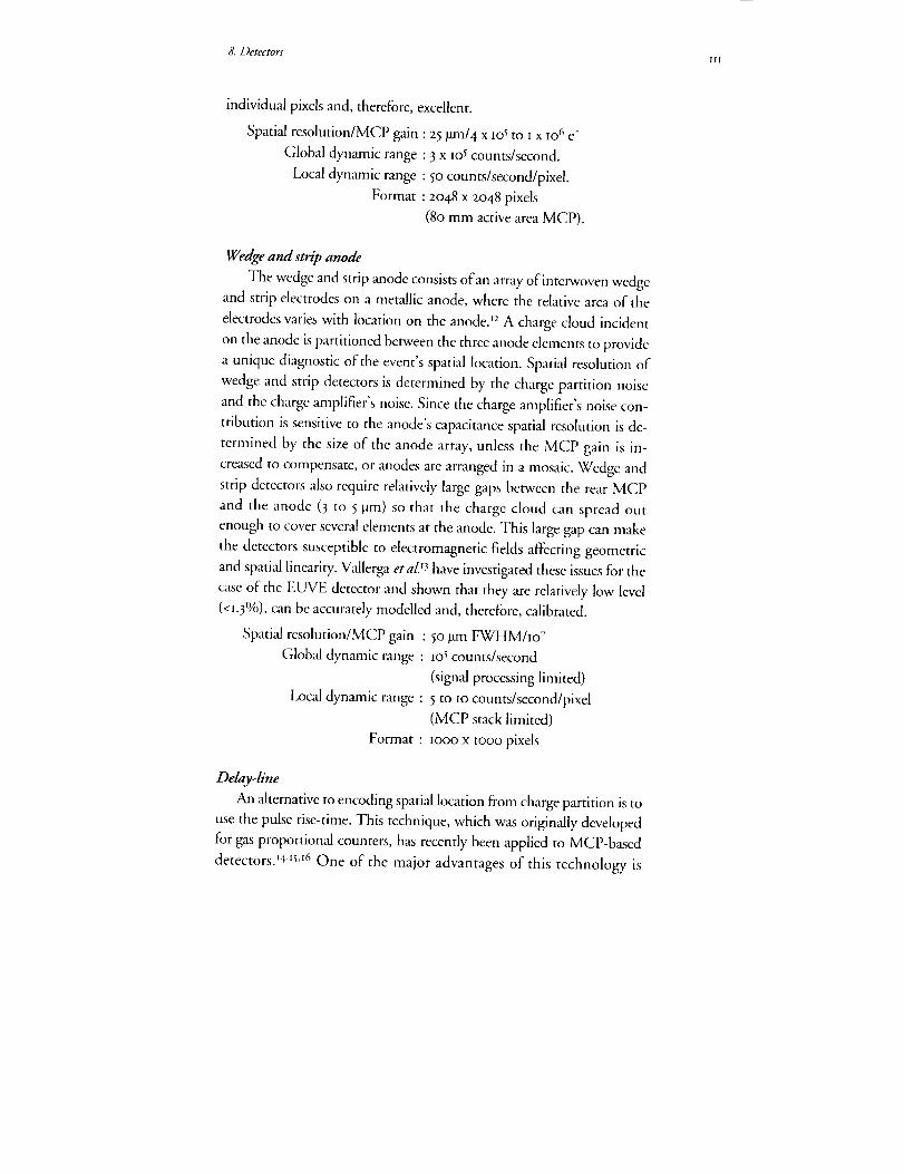
8. Detectors Ill
individual pixels and, therefore, excellent.
Spatial resolution/MCP gain : 25 _m/4 x Io s to i x Io 6 e-
Global dynamic range : 3 x los counts/second.
Local dynamic range : 5o counts/second/pixel.
Format : 2o48 x 2o48 pixels
(8o mm active area MCP).
Wedge and strip anod_
The wedge and strip anode consists of an array of interwoven wedge
and strip electrodes on a metallic anode, where the relative area of the
electrodes varies with location on the anode2 _ A charge cloud incident
on the anode is partitioned between the three anode elements to provide
a unique diagnostic of the event's spatial location. Spatial resolution of
wedge and strip detectors is determined by the charge partition noise
and the charge amplifier's noise. Since the charge amplifier's noise con-
tribution is sensitive to the anode's capacitance spatial resolution is de-
termined by the size of the anode array, unless the MCP gain is in-
creased to compensate, or anodes are arranged in a mosaic. Wedge and
strip detectors also require relatively large gaps between the rear MCP
and the anode (3 to 5 !am) so that the charge cloud can spread out
enough to cover several elements at the anode. This large gap can make
the detectors susceptible to electromagnetic fields affecting geometric
and spatial linearity. Vallerga etal:3 have investigated these issues for the
case of the EUVE detector and shown that they are relatively low level
(<x.3%), can be accurately modelled and, therefore, calibrated.
Spatial resolution/MCP gain : 50 _m FWHMho7
Global dynamic range : lOs counts/second
(signal processing limited)
Local dynamic range : 5 to io counts/second/pixel
(MCP stack limited)
Format : IOOO x moo pixels
Delay-line
An alternative to encoding spatial location from charge partition is to
use the pulse rise-time. This technique, which was originally developed
for gas proportional counters, has recently been applied to MCP-based
detectors. .4as'I6 One of the major advantages of this technology is

H2 FOSI: Frontiers of Space Imaging
that, in contrast to charge partition methods, increasing the format size
does not degrade spatial resolution and may actually improve it. Two
different approaches are currently under development. Siegmund et
aZ14are developing a hybrid two-dimensional planar delay line for spec-
troscopy, which consists of a double delay line structure where the C co-
ordinate is determined from pulse arrival times and the Y coordinate
from charge partition. An alternative approach is the 2-dimensional heli-
cal delay line, which consists of an orthogonal pair of flattened-helicalbifilar transmission lines.'5,'6 Pulse arrival times at the end of each wire
each line give the event location, with the noise pickup and x-y cross talk
being eliminated by differential-mode amplification for each pair oflines.
Spatial resolution/MCP Gain : 18larn FWHM/2 x io7
Global dynamic range : 4 x ioS counts/second
(signal processing limited)
Local dynamic range : 5 to Io counts/second/pixel
(MCP stack limited)
Format : 2ooo x 2ooo pixels
(65 mm diameter)
Intensified CCD
The intensified CCD employs an MCP based intensifier coupled to
a CCD detector, usually by means of a fiber-optic taper. The CCD is
usually operated in a fast-scanning video mode with analysis of each
frame in hardware to determine the centroid of each event, f7 Analog
modes of operation have also been proposed to overcome dynamic
range problems in some situations, though this technique still needs to
be fully explored.
Spatial resolution/MCP Gain :
Global dynamic range :
Local dynamic range :
Format :
Ix_un FWHM/m7
3 X IO4 (CCD frame rate)
5 counts/secondlpixel
(z MCP stack)
2048 x 2048 pixels
(75 mm diameter)
In addition to the MCP readout schemes we have discussed, there
exist a multitude of methods including the resistive anodefi the
quadrant anode,'9 the coded-anode array (CODACON) z° and the
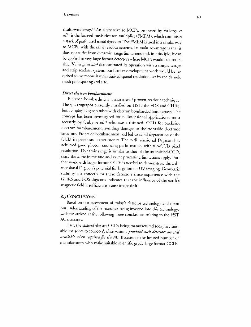
8. Detectors 113
multi-wire array. 21 An alternative to MCPs, proposed by Vallerga et
a/.zz is the focused-mesh electron multiplier (FMEM), which comprises
a stack of perforated metal dynodes. The FMEM is used in a similar way
to MCPs, with the same readout systems. Its main advantage is that it
does not suffer from dynamic range limitations and, in principle, it can
be applied to very large format detectors where MCPs would be unsuit-
able. Vallerga at a/'.zz demonstrated its operation with a simple wedge
and strip readout system, but further development work would be re-
quired to overcome it main limited spatial resolution, set by the dynode
mesh pore spacing and size.
Direct dectron bombardment
Electron bombardment is also a well proven readout technique.
The spectrographs currently installed on HST, the FOS and GHRS,
both employ Digicon tubes with electron bombarded linear arrays. The
concept has been investigated for z-dimensional applications, most
recently by Cuby et aL 23 who use a thinned, CCD for backside
electron bombardment, avoiding damage to the frontside electrode
structure. Frontside bombardment had led to rapid degradation of the
CCD in previous experiments. The z-dimensional Digicon has
achieved good photon counting performance, with sub-CCD pixel
resolution. Dynamic range is similar to that of the intensified-CCD,
since the same frame rate and event processing limitations apply. Fur-
ther work with larger format CCDs is needed to demonstrate the z-di-
mensional Digicon's potential for large format UV imaging. Geometric
stability is a concern for these detectors since experience with the
GHRS and FOS digicons indicates that the influence of the earth's
magnetic field is sufficient to cause image drift.
8. 3 CONCLUSIONS
Based on our assessment of today's detector technology and upon
our understanding of the resources being invested into this technology,
we have arrived at the following three conclusions relating to the HST
AC detectors.
First, the state-of-the-art CCDs being manufactured today are suit-
able for 3000 to Io,ooo ,at observations provided such detectors are still
available when required for the AC Because of the limited number of
manufacturers who make suitable scientific grade large format CCDs,
II4 FrOSI:FrontiersofSpaceImaging
webelieveit tobeinNASA'sbestinteresttoprocuretherequireddetec-torsin thiswavelengthregionassoonaspossible.If suitableCCDsarenotbeingcommerciallymanufacturedatthetimerequiredfortheAC,thecostmayseveralmilliondollars(comparedtoservalhundredthou-sandatthepresenttime).
Second, CCDs are wall suited for zooo to 3o0o fii observations but
they have not been suitably optimized for the AC requirements. We en-
courage NASA to support the development of CCDs optimized for
space flight observations in this spectral region, especially by supporting
the development of thinning, backside charging, and anti-reflection
coating techniques.
Third, the appropriate detector technology for Iooo to 2ooo A ob-
servations is less certain than for the longer wavelength regions and re-
quires considerable development for the AC. We encourage NASA to
continue to support the photocathode-based technology that insures so-
lar-blind operation, especially the use of large-format MCPs and appro-
priate readout technology. We also encourage NASA to support the de-
velopment of the appropriate filter technology (such as Wood's filters),
which might allow efficient solar-blind observations in this spectral re-
gion using CCDs. The combination of efficient Wood's filters and
CCDs optimized in the IOOO to zooo a region would be a significant
advance in detector technology.
ACKNOWLEDGEMENTS
Michael Lesser and Mark Clampin were the principal authors of chapter 8.
REFERENCES
I. Janesick, J., Elliott, T., Collins, S., Marsh, H., Blouke, M., and Freeman,
J. i984, SHE 5Ol, i.
z. Janesick, J., Efliott, T., Daud, T., and McCarthy, J. 1985, SHE 57o, 46.
3. Janesick, J., Elliott, T., Daud, T., and Campbell, D. x986, SHE 627, 543.
4- Lesser, M. P. 1987, Optical Engineering, 26, 911.
5- Coleman, C. I. I98I, App. Opt. 2o,3693.
6. A. Boggess et aI. 1978, Nature z75, 372.
7- A. Boksenberg and C. I. Coleman I973, Adv. Elect. Electron. Physics 52,355-
8. F. Macchetto I982, in The Space Telescope Observatory, NASACP-zz44,4° •

8. Detectors H5
9. O. H. W. Siegmund, K. Coburn and R. F. Malina 1985, IEEE Trails. Nucl.
Sci. NS-32 443-
IO. O. H. W. Siegmund and J. Stock, SPIE 1549, 8I.
tI. J. G. Timothy I98t, Rev. Sci. Inst. 52, U3 I.
12. C. Martin, P. Jelinsky, M. Lampton, R. F. Malina and H. O. Anger
t981, Rev. Sci. Inst. 52, IO67.
U. J. V. Vallerga, G. C. Kaplan, O. H. W. Siegmund, M. Lampton and R.
& F. Malina I989, IEEE Trans. Nucl. Sci. 36 881.
14. O. H. W. Siegmund 1992, Private Communication.
15. S. E. Sobotka and M. B. Williams, I988, IEEE Trans. Nucl. Sci. NS-
35, 348.
i6. Friedman, P. G., Martin, C. and Rasmussen, A. 199o, SPIE Proc. 1344,
I83.
17. J. L. Fordham, D. A. Bone, T. J. Norton and P. D. Read I99o, SPIE I235,
636.
18. M. Lampton and F. Paresce, t974, Rev. Sci. Inst. 45, m98.
19. M. Lampton and R. F. Malina i976, Rev. Sci. Inst. 47, 136o.
zo. W. E. McClintlock, C. A. Bazhi, R. E. Steele, G. M. Lawrence and J. G.
Timothy _98z, Appl. Opt. Zl, 3o7t.
zI. E. Kellogg, P. Henry, S. Murray, L. Van Speybroeck and P. Bjorkholm I976,
Rev. Sci. Instrum. 47, zSz.
zz. J. V. Vallerga, J. Hull and M. Lampton 19, IEEE Trans. Nucl. Sci.
z3. J. Cuby, J. Richard and M. Lemonier 199o, SPIE 123% 294.

n7
9. Filters,Grisms,Polarizers
We have considered in general te_ns what complement of filters,
grisms, and polarizers the Advanced Camera (AC) will require.
In the far ultraviolet (FUV) channel, about 24 filtration elements
will be needed, and in the near ultraviolet optical (NUVO) chan-
nel, more" than about 48 We recommend two or three g?'isms in the
filter wheels of the NUVO wide-field channel, and a set of polariz-
lag filters for at least the UVand NUVO hig,8-resolution channels.
Further development of Wood's filters is required to assure the util-
iff of FUV sensitive charge coupled devices (CCD)s. We recom-
mend an internal flat fiekt system capable of providing reference
)qat field images over the fidl spectral range. A capabili O, to
recalibrate filters on orbit is desirable.
he Advanced Camera (AC) will require filters, grisms, and
polarizers to define scientifically useful spectral passbands andpermit optical analysis of the images over the full wavelength
range moo to m,ooo A. A relatively large filter set will be required to re-
produce the selection of passbands that both Hubble Space Telescope
(HST) and groundbased observers require. The selection of this filter set
will be driven by the science priorities of the AC, and limited both by
the state of technology and the space available within the AC. Later
study phases will prioritize the actual filter choices based on detailed sci-
entific consideration. In this chapter, we outline some general consider-
ations.
9.i CURRENT CAMERA FILTERS
The three cameras built for HST as of late 1993 serve as background
for this report: the Faint-Object Camera (FOC), the present Wide Field
Planetary Camera (WFPC), and the second Wide Field Planetary Cam-
era (WFPC I[) with corrective optics to be installed during the HST re-
pair mission. All three use stacked filter wheels populated by a large
PRECEDING PAGE BLA_,iK NOT F,,.,_,,_D_;"_'_-' PAG_ IIb_ Ir'JTE:_(tO,r'_ALL;bLk;,>:
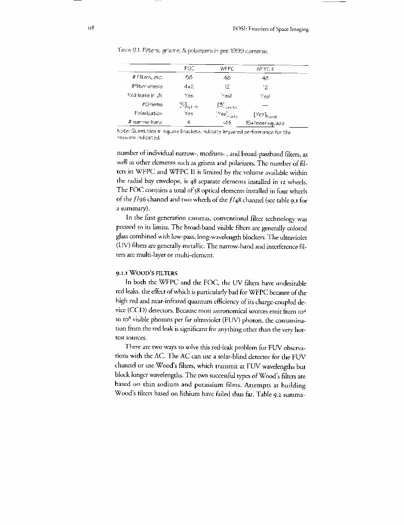
it8 FOSI: Frontiers of Space hnaging
Table 9.1. Filters, grisms, &polarizers in pre-1999 cameras
FQC WFPC WFPCil
# filters, etc. 58 48 48
#filter wheels 4+2 12 12
Red leaks in UV Yes Yes]J Yes!
#Grisms [5]s#, Cb [3]Sph AB --
Polarization Yes [Yes]_ia I [Yes]_a_iaI
# narrow-band 4 ~14 15+linear+quads
Note: Quantities in square brackets indicate impaired performance for thereasons indicat,ed.
number of individual narrow-, medium-, and broad-passband filters, as
wall as other elements such as grisms and polarizers. The number of fil-
ters in WFPC and WFPC II is limited by the volume available within
the radial bay envelope, is 48 separate elements installed in I2 wheels.
The FOC contains a total of 58 optical elements installed in four wheels
of the f/96 channel and two wheels of the f/48 channd (see table 9-_ for
a summary).
In the first generation cameras, conventional filter technology was
pressed to its limits. The broad-band visible filters are generally colored
glass combined with low-pass, long-wavelength blockers. The ultraviolet
(UV) filters are generally metallic. The narrow-band and interference fil-
ters are multi-layer or multi-element.
9.I.I WOOD'S FILTERS
In both the WFPC and the FOC, the UV filters have undesirable
red leaks, the effect of which is particularly bad for WFPC because of the
high red and near-infrared quantum efficiency of its charge-coupled de-
vice (CCD) detectors. Because most astronomical sources emit from lO4
to lo 8 visible photons per far ultraviolet (FUV) photon, the contamina-
tion from the red leak is significant for anything other than the very hot-
test sources.
There are two ways to solve this red-leak problem for FUV observa-
tions with the AC. The AC can use a solar-blind detector for the FUV
channel or use Wood's filters, which transmit at FUV wavelengths but
block longer wavelengths. The two successful types of Wood's filters are
based on thin sodium and potassium films. Attempts at building
Wood's filters based on lithium have failed thus far. Table 9.z summa-
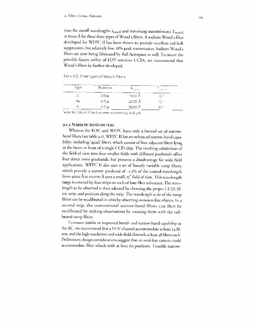
9. F_i/ters, Grisms, Pohtrizers H9
rizes the cutoff wavelengths Xc,t,,ff and remaining transmissions T6oooA
at 6ooo ,_tfor these three types of Wood's filters. A sodium Wood's filter
developed for WFPC II has been shown to provide excellent red-lcak
suppression, but relatively low, r8% peak transmission. Sodium Wood's
filters are now being fabricated by Ball Aerospace as well. To assure the
possible future utility of FUV-sensitive CCDs, we recommend that
Wood's filters be filrther developed.
Table 9.2. Three types of Wood's fiPters
Type Thickness )V _:.;_ _ ,:;._,,
Li 0.5 tJ 1600 _ 10 ;
Na 0.5 tl 2000/_ 10 :
K Q.5 _ 3200 )_ 10 '_
Note: No Lithium filter has been successfully built yet.
9.I.2 NARROW-BAND FILTERS
Whereas the FOC and WFPC have only a limited set of narrow-
band filters (see table 9.1), WFPC II has an enhanced narrow-band capa-
bility, including 'quad' filters, which consist of four adjacent filters lying
in the beam in front of a single CCD chip. The resulting subdivision of
the field of view into four smaller fields with diflbrent passbands oflbrs
four times more passbands, but presents a disadvantage for wide-field
applications. WFPC II also uses a set of linearly variable ramp filters,
which provide a narrow passband of-1.5% of the central wavelength
from 4ooo _ to Io,ooo _ over a small, I3" field of view. This wavelength
range is covered by four strips on each of four filter substrates. The wave-
length to be observed is then selected by choosing the proper CCD, fil-
ter, strip, and position along the strip. The wavelength scale of the ramp
filters can be recalibrated in orbit by observing emission-line objects. In a
second step, the conventional narrow-band filters can then be
recalibrated by making observations by crossing them with the cali-
brated ramp filters.
To ensure similar or improved broad- and narrow-band capability in
the AC, we recommend that a FUV channel accommodate at least 24 fil-
ters, and the high-resolution and wide-field channels at least 48 filters each.
Preliminary design considerations suggest that an axial-bay camera could
accommodate filter wheels with at least 60 positions. Tunable narrow-

J2o FOSI:Frontiersof Space Imaging
band filters for the full FOV would be ideal (e.g., based on Fabry-Perot
etalons), but peak transmission would need improvement over the low
values that are customary. Therefore, we recommend that whatever nar-
row-band filter solution is finally adopted, it should not impact negatively
on the wide- and intermediate-band filter capability, on which the ma-
jority of science projects with HST rely.
9.i.3 GRISMS
Both the FOC and WFPC provide sets ofgrisms for slidess spectros-
copy, but because of the spherical aberration of HST this capability has
been virtually useless, The replacement camera WFPC II does not con-
tain any grisms, and thus the capability for low-resolution, large-field spec-
tral surveys will be very limited at least until the AC. Arguing in favor of
AC grisms is the utility they have shown on ground-based telescopes for
surveys of point sources, such as planetary nebulae, and QSOs. The reso-
lution gain of the corrected HST point-spread function will translate into
faint detection limits for grism work, which will be further helped by the
darker sky in orbit. Table 9.3 shows signal-to-noise ratios that would have
been attainable with WFPC, had HST not had spherical aberration. With
detector and throughput improvements to he expected for the AC, it seem
likely that HST will remain competitive with even the largest ground-
based telescopes, with a clear advantage in crowded fields and in the UV.
Therefore, we recommend a limited set of about two to three grisms in
the filter wheels of the wide-field channel.
Table 9.3. Predicted grism performance for WFPC
v S/N(biue) S/N(red)
21 21 44
22 1_ 25
23 5 13
24 2 6
Note: Abovesignal-to-noise ratios computed for WFPCwithout sphericalaberration, _= 60 - t20/_, and exposuretime of 1800 sec.

9. Filters, Grisms,Polarizers Izl
9.i.4 POLARIZERS
All three preq999 cameras feature some polarizing filters to measure
polarization. Because of the near 45° reflection necessary to feed the WFPC
and WFPC II in the radial bay, only relatively strong polarizations can be
measured by these two cameras. On the other hand, the recommended
axial location of the AC may permit the measurement of weaker polariza-
tion in straight-through optical configurants. To take advantage of this
opportunity, we recommend the inclusion of a set of polarizing filters in
the filter wheels of at least the FUV channel and, if possible, all the chan-
nels without off-normal reflections.
9.2 CALIBRATION
The AC should incorporate by design an internal flat-fielding system
capable of providing reference flat-field images over the full IlOO to
IO,Ooo ,alspectral range of the camera. In many science applications, the
degree to which images in different passbands can be flat-fielded deter-
mines the effective limit for detection or measurement (e.g., color gradi-
ents of extended sources, stellar photometry over wide fields, etc). We
have learned that flat-fielding by sweeping across the Earth yields too
many photons for the broad-band filters of WFPC. Therefore, the AC
must have internal flat-fielding capability, as indeed will be the case in
WFPC II. Also, a capability to recalibrate all filters in orbit is desirable,
but may be only partially achievable.
ACKNOWLEDGEMENTS
Francois Schweizer was the lead author of chapter 9, and John Hoesselcontributed.


lz;
10. Instrument Computer
We/save examined the fi_nctional requirements fi)r the instrument
computer, and find that a robust computer will be required to as-
sure adequate detector control, data compression, self-documented
data, and possible autonomous guiding. A large memory will be re-
quired to/sold at least one or possibly more frames /br on-board
processing,
n considering the scientific requirements for an Hubble Space Telc-scope (HST) Advanced Camera (AC), it is clear that the capabilityof'the on-board data system is a crucial element, one that can poten-
tially limit the scientific success of" the instrument. In this context, the
on-board data system includes the detector outputs, readout controllers,
on-board computer, and ground system. (See chapter 8a.3 for a discus-
sion of the charge coupled device (CCD) detcctor controller require-
ments.) For downlink, the concerns are mostly in the area of data band-
width and compression. For uplink, the issue is the predictability' of the
state of a highly, capable instrument so that efficient commanding is pos-
sible.
This chapter discusses six specific issues pertaining to the data system
for the AC:
• Data volume
• Data compression
• Memory requirements
• Use of a common computer system
• Processor speed
• Operational concerns
IO.I DATA VOLUME
To improve on the 16oo x i6oo pixel Wide Field Planetary Camcra
(WFPC) design, which digitizes to Iz bits per pixel, the AC will employ
at least a zo48 x 2048 pixel detector with at least i6 bits per pixel. How-
PRECEDING PAGE BLANK NOT ,,.._v,.:;..,r-_-',,-,,:.r_, PAGE Io_ INTEN-fl0NALLY BLANK

124 FOSI: Frontiers of Space Imaging
ever, in oMer to accommodate the high resolution, high contrast, wide
field imaging capability that is unique to the HST, the AC should con-
tain one 4096 x 4096 pixel detector with I8 bit digitization. This implies
a data volume of 3o2 Mbits / image readout. At the spacecraft-limited
rate of one Mbit/second, each readout requires roughly five minutes to
dump to the Science Tape Recorder (STR). As will be shown below, this
rate would be a severe limitation for a moderate speed, multiport CCD
unless a significant amount of local data memory is available. Since the
STR can hold and dump only one 2o-minute segment of data (absolute
maximum) per orbit, without data compression there will be a maxi-
mum of four AC readouts per orbit. Even if we were dumping directly
from instrument memory, the amount of Tracking and Data Relay Sat-
ellite System (TDRSS) downlink access time is well matched to the STR
limitations, and the result is not substantially different. Since we want to
operate the AC in fast framing and parallel observation modes, an effort
must be made to reduce the data volume.
10.2 DATA COMPRESSION
Direct, lossless data compression today can routinely achieve factors
of 2 to 4 in compression. More advanced (and probably more compute
intensive) methods can provide up to a factor of ten. However, when
discussing the feasibility of data compression strategies, it is important to
look at the overall data transmission system. For instance, a particularly
difficult possibility is that when data is compressed twice (say, once by
the instrument, and again during the TDRSS transmission), some algo-
rithm combinations actually lead to data expansion. The benefit of such
direct compression schemes is that they are straightforward to imple-
ment and, when properly integrated, work transparently.
Other forms of compression that do not involve direct interaction with
the data stream may be more useful to consider. These require intelligent
on-board control of data collection and, in many instances, can be much
more effective. Readout of a subset of the available pixeis is an example,
although it may not be applicable for wide-field science. For fields where
photometry is required at known positions, on-board selection and read-
out ofsubimages can significantly reduce the data rate. For CCD's using
long exposures, the possibility arises for taking multiple frames and do-
ing cosmic ray filtering before transmission. Such strategies could reduce
bandwidth significantly with almost no loss of capability, but would re-

I o. Instrument Computer i z5
quire a relatively powerful on-board processing capability.
Finally, it is also possible that some of the compression can take place
using specialized readout modes of the detectors. In particular, ifCCD's
are used, then on-chip pixel summation is a standard strategy,. (See chap-
ter 8 for details on these modes.)
Io.3 MEMORY REQUIREMENTS
For large format detectors, an important factor is the memory capac-
ity of the processor since we are assuming that full flame(s) can be stored
and operated on. Assume also that 8-bit error correction is used so that
each 3z-bit word actually requires 4o bits of physical memory. A full
flame has one Mpixels. For IS-bit pixels this translates into 302 Mbits
(with data packing) or 38 Mbytes. With error correction, the real physi-
cal memory required is 48 Mbytes.
For planetary imaging, the data memory requirements are much
greater due to ephemeral nature of planetary objects. Many investigations
will benefit from three color imagery; for instance dust clouds on Mars
are best differentiated from ice clouds by comparison of yellow
(green+red) and blue images. For such planetary imaging, the acquisition
of imagery in three colors must be accomplished within a relatively short
time period, else rotation will occur between the frames. (See table 1.2)
It will be possible for the AC to use a moderate speed, multi-port
CCD, so that an image could be read out in less than a second, and the
time between flames could be simply the time required to rotate filters.
The flame transfer region of CCD chips is a relatively inexpensive
form of local memory. A flame transfer chip can contain two full frames,
so that the total acquisition time for three frames is equal to the readout
time of one flame (plus cycle time of filter rotation, etc.). A double
frame transfer CCD could be used to accumulate three images "on
chip." Unfortunately, cosmic rays also accumulate as the image waits for
readout and, in the case of bright extended planetary objects, it will be
difficult to detect such cosmic ray events.
Due to the cost of memory, it may be necessary to utilize sub-array
readout for "fast framing" operation, but the data volume is still quite
substantial. In order to utilize the high resolution capability of the cor-
rected HST for imaging Jupiter, at least a iooo x Iooo pixel array must
read out for each frame, equal to 48 Mbits of uncompressed (and with-
out error correction) data for three frames.

lz6 FOSI:Fron6ersofSpaceImaging
It isimportanttonotethat,internaltotheinstrument,it isdatavol-umeandnotdataratethatisthelimitingfactor.Largeformatdetectorscanbearrangedtohaveparallelreadoutchannelsthatcansubstantiallyincreasetheaggregatedata.I,ocalmemoryisthenusedtomatchthisin-ternalratetotheexternalinterfaces.
IO.4 COMMONCOMPUTERSYSTEMTheHSTProjectiscurrentlydiscussingthepossibilityandmeritsof
commoncomputersystemsin thefutureScience Instruments (Sl's) and
for spacecraft functions (e.g., coprocessor for DF-zz4). The benefits are
decreased maintenance costs and perhaps even development costs. Such
common systems, if feasible, would require only a single type of simula-
tor and skill to maintain, and would therefore contribute to the cost effi-
ciency of the long-term HST program. However, there is also a loss of
flexibility' for the instruments when such a critical subsystem cannot be
fully optimized. These discussions are not yet complete, but a number of
results are useful for this study.
The systems being considered for Near-Infrared Camera
(NICMOS) and Space Telescope Imaging Spectrograph (STIS) are
based on either 386 or TI C3o hardware (or both). The coprocessor be-
ing developed for the flight DF-224 is also 386 based. This provides a
guideline for the computing capability that can easily be envisioned for
the AC. While a 386 provides a nominal amount of computing capabil-
ity by today's standards, it will no doubt be woefully obsolete in the AC
time frame, if not sooner.
The N1CMOS/STIS experience can be applied to the AC in the
sense that flight computers of these instruments are expected to be able
to support the kinds of commanding and data processing capabilities
that have been discussed for the AC. This includes 'macro'-type com-
manding capabilities, some degree of acquisition autonomy (limited
more by the ground system than on-board capability), data manage-
ment in on-board memory, interactions with the STR, data formatting,
as well as the usual mechanism and detector control functions. The
main difference for the AC is in data volume; the computers' capabilities
hopefully will be substantially increased. Note that on-board data pro-
cessing for the STIS using the currently envisioned data system was
slightly marginal when 2o48 x 2o48 detectors were still being considered.
IO.Instrument (]omputer Iz7
IO. 5 PROCESSOR SPEED
In addition to the on-board processing schemes mentioned previ-
ously, it is also possible to use this capability to improve image qualit T in
some cases. For example, when using photon counting detectors, it is
desirable to create a synthetic image in real-time, while monitoring the
telescope pointing, in order to correct for pointing errors. However,
such capabilities require substantial computing power.
As a crude estimate of 386 processing power, assume that each pixel
requires anywhere from 4 to 2o lasec of central processing unit (CPU)
time. This works out to a full frame processing time of one to six min-
utes. These numbers are somewhat high, considering that the CPU
must also deal with real-time events and multiple detectors. However,
proper event-driven design may still make this feasible.
IO.6 OPERATIONAL CONCERNS
For a camera that has a powerful on-board computing capability,, the
possibility, arises for autonomous operation that can substantially in-
crease efficiency for certain classes of observations. This capability
should be explored and exploited to the maximum extent possible in or-
der to keep the AC competitive. For example, automatic sequencing of
multiple color exposures, self-guiding capabilities, and dynamic subarray
selection for processing are usefid fbr meeting the proposed minimum
scientific requirements. However, detailed interaction with the ground
system needs to be considered, particularly for command generation and
data interpretation. It seems that a sdf-documenting protocol for the
state of the camera needs to be developed for the downlink.
m. 7 SUMMARY
Given the detector improvements that will be incorporated into an
AC, this instrument will need a very capable on-board data processing
system that will allow for efficient observations. A flexible design will
also enable future optimizations in AC operation to exploit unforeseen
opportunities.
It appears that unless some development is done on faster processors
and cheaper memory, we will be running into practical data processing
limitations with the 4o96 x 4o96 pixel class detectors. While flight quali-
fication of better processors cannot be assured fi3r the development time
frame of the AC, every ef_brt should be made to pursue improving this
128 FOSI: Frontiers of Space Imaging
capability. Greater processing capability will enable using data compres-
sion and other more sophisticated data management techniques to
handle the large data volume required.
We recommend that more sophisticated data handling techniques
be vigorously pursued in order to enable the most efficient and cost-ef-
fective science capabilities for the next generation of imaging systems.
ACKNOWLEDGEMENTS
Edward Cheng was the lead author of chapter io. Richard White
contributed the section on data compression.

129
11. OneCameraDesign
This section describes one conceptual design for the Advanced
Camera (AC), which was developed in Spring I993 for a proposal
to European Space Agency (ESA). It is described here to illustrate
major tec/mical issues, show/sow the science priorities can be ad-
dressed, and render a preliminary argument that the AC isfeasible
in technical and programmatic terms. This design also provided
the starting point for the NASA Phase A study of Summer I993,
which looked at trades and options, and assessed the required re-
sources of time and money for the AC.
he essential features of this conceptual design are defined by our
preliminary choices for the detectors. The f-numbers of thecamera modes are chosen to reconcile the performance priori-
ties to the detector formats. The performance priorities (see chapter t.z)
are stated in terms of the desired field of view (FOV) and fineness of
sampling, which are essentially field angles on the sky. Detector formats
are given by the pixel spacing in microns (_m) and the number of rows
and columns in the pixel array. The f-number of a camera mode deter-
mines the image magnification--in particular, how many detector pix-
els receive the light from one spatial resolution element on the sky.
II.I CAMERA MODES
In response to our survey, the astronomical community expressed a
strong desire for the AC to provide critical sampling at both long and
short wavelengths. (See chapter 7.) Critical sampling means the detector
subdivides just finely enough to capture all the spatial information the
image contains.
For a diffraction limited telescope, one resolution element corre-
sponds to the field angle Z/d, where k is the wavelength of light and d is
the diameter of the aperture. According to the Nyquist criterion, critical
sampling calls for two samples per resolution element, which implies a

I3o FOSI: Frontiers of Space hnaging
pixd spacing ofk/2 times the f-number of the camera. Even if the detec-
tor pixels undersample the image by as much as a factor of two, it may
be possible to recover nearly the full information operationally. This
would involve 'substepping'-----or taking other images displaced by frac-
tions ofa pixel--and analyzing all the images as an ensemble. (See chap-
ter 7.)
For each of the two wavelength regions of the AC--the near ultra-
violet/optical (NUVO) and the far ultraviolet (FUV)--we have
basdined a single detector in this design. (Detectors are discussed in
chapter 8.) D_, the baseline NUVO detector, is a charge-coupled device
(CCD) with an 8192 x 8192 x 7.5 _ format. It is a mosaic of four 4096 x
4o96 arrays, each of which can be reformatted independently by on-
chip binning into pixels that are larger in size and smaller in number by
programmable powers of two. In the FUV range, we have baselined a
photocathode detector, D2, with 2o48 x 2o48 x 25 _n pixels.
Table u.i shows the modes in this design. Modes I and 2 satisfy the
highest two of the three NUVO science priorities, except that the speci-
fied sampling is achieved at a I4% longer wavelength. Mode 2 provides a
FOV that is twice as large in linear dimension as the science recommen-
dation in chapter I.
Tabb 11.1.Modes of the AC.
Ivtode # f/ Detector Binning1 T_Vd2e 5an3:'
1 24 D. 2x2 CCD NUVO
2 24 1/4 D_ I ×1 C;CD NUVO
3 192 D n/a PC FUV
4 _ -- D,.I ?) - CCD NUVO
!Corono_jraph: un_der study, not in baseiine.
Format FOV_' Pixe;_ Critical Sampling4096 x4096 221" 0.054" X>12.600
x 15 F._rn4096 x4096 110" 0.027' X>(5260_\
x 7.5 _m2048 x 2048 23' 0.011" X>2600 ,_,
×25 l_m,
_' _. Far ultraviolet (FUV): 1000 2500 ,_.>_Near ultraviolet/optical (NUVO): 2_00 - 10,000
:5Ma×imum due tc detector and f-nL, mber. Linear dimension.
4Anaularsubtense oFonevixel.j - .
Mode 3 addresses--but does not fully satisfy--the two FUV priori-
ties; the sampling is too coarse for the high resolution FUV specification
and the field is too small for the wide field FUV specification. Thus,
Mode 3 should be regarded as one possible compromise with two prob-
lematic issues for the FUV, O) uncertainty about the shortest wave-
length for which critical sampling is actually beneficial in the case of the

*L One Chmera Desi_ l_i
as-built Hubble Space Telescope (HST), and (z) availability, ofa FUV
detector with eit/3er a larger format than Io24 x Io24 or smaller pixels
than 25 _rn (see chapter 8).
Mode 4--the NUVO coronograph--is a desirable option, but it is
not included in this design. Further effort is needed to study the implica-
tions of either making it a sub-mode of Mode 2 with DI as the detector,
putting a second set of optics behind the fh9z aperture and using a new
NUVO detector (D_), or other possible implementations.
II.2 FOCAL PLANE CONSTRAINTS
Based on the analysis and recommendation in chapter 6, this design
is fbr the AC installed in an axial bay. Figure iia shows the HST focal
plane with the AC and three other axial instruments in place. The ar-
rangement of the f/z4 and f/I92 relay entrance apertures are con-
strained by the proximity of the corner of the box and by the mechanical
interface with the Optic;fl Telescope Assembly (OTA), as shown in fig-
ure H.2. The 2oo" x 20o" (nominal) aperture of the AC is the largest
unvignetted FOV available. A grazing-angle reflection, shown in figure
I1.3, is required to divert the beam of the f/24 relay away' from the comer
of the box in order to implement the large prima D, mirror. This angle
should not be larger than 8o ° if one wants to keep the length of the di-
verting mirror within reasonable limits (415 mm for 80°). The fhg2 re-
lay is a straight-through configuration. The positions of both FOVs are
completely determined by the need to fit the primary mirror of the J'h9z
channel within the inner corner of the box and to clear the fh92 beam
past the f/z4 diverting mirror.
l_,t; p,m
10I 4
1Figure 11.1.HSI_focal
plane showing the ACand its two entrance
apertures

t32 FOSh Frontiers of Space Imaging
T
(.;TA Opt i<a_/'_i,,
p!ate
Figure 11.2.
Available space ofthe HST focal
plane for the ACentrance aper-tures.
FO_.,f/19:
FOr f/24
"'7"-.
Figure 11.3.The
optical design isphysicallyrealizable with the
dual aperturelayout shown inFig. 12.1.
H. 3 NOMINAL OPTICAL DESIGN
As was learned from the optical studies for the Corrective Optics
Space Telescope Axial Replacement (COSTAR), the large OTA spheri-
cal aberration must be corrected at an image of the telescope exit pupil in
order to provide a correction over the entire field of view of the camera.
Therefore, the AC nominal design includes a large primary mirror (PM)
that reimages the OTA exit pupil onto an aspheric secondary mirror
(SM) that implements the correction. A third mirror (MMx) permits the
desired magnification and detector location. The mirror positions and
tilt are chosen to correct for the HST astigmatism, image tilt, and cam-
era field aberrations. Some residual axial coma can be compensated by
slighdy decentering the pupil image with respect to the secondary mirror.

H. One Camera Design 133
II. 4 ADOPTED OPTICAL SOLUTIONS
ii.4.! f/24 CHANNEL
As shown in figure ii. 4, the first element in the f/24 channel is the
80 ° incidence folding mirror (FM) required in order to fit the channel
within the axial bay envelope. The field of view is centered at 6.6 arcmin
from the telescope axis. The primary mirror distance from the OTA fo-
cal surface is I9oo mm, the PM to SM distance is 905 ram, and the pupil
diameter is 29.7 ram. All three mirrors with power have axially symmet-
ric spherical or aspherical figures.
In the f/z4 channel, the main difficulty is to compensate fully for the
astigmatism variation over the 2o0 x zoo arcsec field of view, which is
very large. Based on optical analysis, we can achieve this compensation
and expect an excellent Strehl ratio at 55oo fi over the whole field of
view.
IL-_______ Figure 11.4.Optical design of the_ f/24 channel
_-_ ut,t
IL4.2 f1192 CHANNEL
As shown in figure II.5, the f/I92 straight-through channel is cen-
tered at 8 arcmin from the telescope axis. The PM and SM have been
placed to obtain a sufficiently large image of the exit pupil that the toler-
ances for maintaining the exit pupil image on the secondary and the
manufacturing difficulties of this mirror are kept within reasonable lim-
its. The PM distance from the OTA focal surface is i9oo mm, the PM
to SM distance is 640 ram, and the pupil diameter is zt ram. (For com-
parison, the already-Fabricated COSTAR mirror for the f/96 FOC re-
lay--fh5r after correction by COSTAR--is a 15mm diameter anamor-
phic asphere.) The PM is spherical and the SM is an axially symmetric
asphere.

_34 FOS[: Frontiers of Space hnaging
The f/s9 z high resolution mode is obtained by a toroidal MM, and a
folding flat MM2, which feeds the image to Dz, the solar-blind, FUV
detector. The optics of this mode are diffraction limited at Izoo A over
the whole field of view (Strehl ratio > o.8).
Figure 11,5, Optical design of thef/192 channel.
i i.4. 3 ADDITIONAL f/192 CHANNEL OPTIONS
The f/Igz channel can accommodate the coronographic option, Mode
4, which is not part of our baseline design, but which is under study. Fig-
ure 11.6 illustrates this fl86 coronographic mode, which makes use of a
separate CCD detector (D3). MM_ and MM, would be changed to dif-
ferent toroidal and aspherical prescriptions. A mechanism to change the
fourth mirror could probably be avoided by using two different, fixed mirrors
MM2 at slightly off-plane positions. As one of these latter mirrors is a flat,
flexibility is provided in the rdative location of the detectors D, and D 3.
/_ t .....
Figure 11.6. One concept for the optical
coronograph, Not in the baselinedesign.

zz. One Camera DesiLm 135
To implement the apodization, a f_eld occulter would be located at the
intermediate real (and corrected) image (RI), which is located between
MM_ and MM,, and the Lyot stop would be placed at the second reimaging
of the exit pupil (EP), which is located between MM, and D 3. This mode
is diffraction limited over a 50" x 50" FOV at 5000 A (Strehl ratio > 0.93)
and near-diffraction limited at/zoo _ (Strehl ratio 0.9 at center and 0.3
at the extreme field of view corner.)
As a whole, the current optical design of the f/192 channel allows
much flexibility to respond to developments during the early study
phases of the AC. For example, were developments to permit us to con-
sider a 7.5 _trn pixel CCD with a Wood's filter as a feasible option for the
FUV detector Dz, an f/96 mode satisfying the FUVcritical sampling re-
quirement could be easily implemented by only changing MM; of the
current f/I92 mode to a flat feeding this new detector directly. The same
CCD as in the NUVO mode could probably be used, though with a
different surf]ace treatment for the FUV.
II. 5 ADOPTED DETECTORS
Tables ll.Z and I1.3 give the detector performance specifications we
have baselined for this AC design. In chapter 8, we discuss the issues re-
lated to achieving these specifications using the two major classes of de-
tectors: CCD and photocathode-based photon counters (PC).
Table 11,2, Functional specifications for near ultraviolet/optical (NLIVO) detector.
Format 4096 x 4096 x 7.5 _ on chip binning fornormal 2048 x 2048 mode
Design 2-side buttable to make 2 x 2 array
Wavelength range AR coatings optimized for 2000 to 10,000/_
Thinnable for back illumfnation wfth stable
backside charging,
10 _rnp-v2 to 4 electrons rrns @5Q kHz or greater< 20 electrons/pixel/hour> 0.9999995Q to 1QQ%in2000 to 10,000/_ region.> 10_electrons (15 lam-equivalentpixels)and 2.5 × _04(7.5 Wnpixels)
Imaging surface flatness
Read noise
Dark current
Charge transfer efficiency
Quantum efficiency
Dynamic range

J36 FOSI: Frontiers of Space Imaging
Table11.3.Functional specifications
FormatWavelengthrangeSpatial resolutionDark count rateFlat field uniformityQuantum efficiencyVisiblelight rejection
DynamicrangeLocaldynamic range
for the far ultraviolet (FUV)detector.
minimum2048 x 2048 resolution elementslooo to 2000
less than 25 I_n FWHMtess than 20 counts/sec/cm 2at least 7%RMS~20% at 1216/_and 10%to 15%at 1400/_
(1) CCDdetector with Woodsfilter requires10.8(2) MCPdetector requires10-6minimum5 x 105counts/sec over detectorbetter than 50 counts/sec/pixel
II.5.I NUVO DETECTOR Dl
The AC will require thinned, back-illuminated CCDs to achieve the
desired ultraviolet sensitivity. In the front-illuminated mode, which is
how most off-the-shelfCCDs operate, light must pass through the elec-
tronic structures that define the pixels. This absorbs or reflects most ra-
diation of X < 4ooo/_. before detection. Back illumination avoids this
problem, as the light can pass directly into the silicon. However, to as-
sure that the electrons produced can be collected, it is necessary to thin
the silicon layer to allow the photo-generated electrons to be detected at
the CCD frontside.
In this design, the NUVO subsystem is implemented in a single op-
tical configuration using a 2 x 2 mosaic of back illuminated CCDs. The
individual CCDs will be 4o96 x 4o96 x 7.5 _m pixel devices. In the wide
field mode, Mode i, all four detectors are read out simultaneously, with
each CCD being binned 2 x 2 on-chip to provide effectively four zo48 x
2o48 x 15 _m devices. The optical sampling is therefore equivalent to a
single 4o96 x 4096 x I5 _rn pixel CCD, with two small gaps running
through the center of the image where the CCDs butt together. These
gaps can be made less than Io pixels wide.
In the high resolution Mode 2, only one 4o96 x 4o96 pixel CCD is
read out. This provides twice the resolution of the wide field mode over
one-fourth the area of the sky. In the baseline optical design, this mode
provides full Nyquist sampling at 6250 A. (The other three 2048 x 2048
CCDs are not used.) This mode is multiply redundant, since any of the
four CCD detectors could be used as the Mode 2 detector.
n.5.2 FUV DETECTOR D2
Based on emphatic community input, the response of the FUV de-
tector should be strictly limited to FUV radiation and block contamina-
H. One Camera Desig_ I_7
tion of the images by light from normal stars. To achieve this 'solar
blind' performance, we must choose between two entirely different tech-
nologies for the FUV detector D2. The first type, PC detectors, are in-
sensitive to red light without a blocking filter. The other, the CCD, is
very sensitive to red light, and requires a blocking filter in front of it,
known as a 'Wood's filter.' A Wood's filter employs a thin layer of an al-
kali metal to absorb light at frequencies higher than the plasma fie-
quency of the free electrons. The result is that FUV light is transmitted
to the CCD, and red light is absorbed.
Our choice to use the PC instead of the CCD/Wood's filter combi-
nation in this conceptual design was not simple, nor can it be regarded
as final until the availability of a PC detector is assured. Both technolo-
gies require development to assure the required performance. We be-
lieve the PC choice is currently the more solid option.
The PC has excellent imaging capabilities in the FUV region, and
the performance factors that make them preferable over CCDs are their
noiseless photon counting ability, relatively high quantum efficiency
(QE), lack of sensitivity to red light, and high-frequency timing capabil-
ity, which benefits observations of time-variable phenomena. (It may
also provide an operational way to shutter out pointing jitter to improve
image quality under some conditions.)
We currently envision that Dz will consist of a CsI photocathode,
which converts the FUV photon into a photoelectron, a micro-channel
plate (MCP), which amplifies the photo-electron into a 'cloud' of IOs to
lO6 electrons, and a readout device, which encodes the position of the
electron cloud within the detector format. FUV detectors of this general
design have been used on a number of recent extreme ultraviolet and x-
ray instruments in space, including the Roentgen Observatory Satellite
(ROSAT), the Extreme Ultraviolet Explorer (EUVE), and the Hopkins
Ultraviolet Telescope (HUT). Our current concept for Dz is based on
the FUV detector for STIS, a second generation HST instrument.
The original STIS MAMA detectors had the format specified in
table 11.3 until they were downsized from a 2048 x 2048 to a lO24 x IO24
format in a descoping exercise to reduce cost and schedule risk. The
MAMA package typically comprises a single curved MCP and a multi-
anode array that consists of two orthogonal layers of interwoven
anode elements, which define the array of discrete pixels.

I38 FOSI: Frontiers of Space Imaging
ACKNOWLEDGEMENTS
Aden and Marjorie Meine] contributed the initial optical designs and analysis
of the AC for this study. Starting with their work, Michel Sa'isse further
developed the camera design presented here.
139
12, ScheduleUrgencyof theAdvancedCamera
When # the Advanced Camera (3C) needed, and u,hen must it be
started? The 1999 Hubble Space Telescope (HST) sm,Mng mission
is required for other reasons--to reboost the orbit to prevent reen-
oy. "/'he AC is needed in I999 to asswv HST can provide an ad-
equate imaging capabili_. The d C must be started now and devel-
oped on an agcressive schedule to assure it can be insmlkd on t'he
099 flig'ht opportun@.
he urgency for initiating effort on the Advanced Camera (AC)
is determined by, the National Aeronautics and Space Admini-stration (NASA)'s estimation of when the instrument will be
required for installation, and then backing off from that future date by
the length of time needed to develop the AC. To investigate the urgent,
of starting work now we must question those two assumptions.
I.Z.I INSTRUMENT DEVELOPMENT TIME
The development of instruments has emerged as the most difficult
element of space science, at least in terms of the cost growth and sched-
ule delays which have been experienced. Historically, on the Hubble
Space Telescope (HST) Program, instruments have suffered many years
of delays due to problems with the initial development effort and the
Challenger accident. Second generation instrumcnts, such as the second
Wide Field Planetary Camera (WFPC I1), Space Telescope Imaging
Spectrograph (STIS), and Near-Infrared Camera (NICMOS) were rc-
peatedly delayed by funding cuts and reprioritizations dictated by the
difficulties Facing the HST program before and after launch. If those
trends continued, it would not be possible to build an instrument in
twelve ycars, let alone six.
After the discove_ of spherical aberration, plans were laid out to de-
velop corrective optics, both through modifications to the WFPC II and

140 FOSI:Fro,ltiersofSpacelmaging
with theCorrectiveOpticsSpaceTelescopeAxialReplacement(COSTAR).Despitethechallengeandimportanceofthiseffort,andlowerfinancialreservesthanusualforbuildinginstruments,thesedevelopmentactivitieshavedeviatedsubstantiallyfrompreviousNASAandHSTin-strumentexperienceandarestillonschedulefortheDecember1993launchdate.PartofthisgoodperformanceisduetogettingtheextraattentionandprioritythattheHSTfirstservicingmissionreceives,butsomein-roadshavealsobeenmadeinreducingtheturn-aroundtimefordecisionsandstreamliningsomeofthebureaucracythathasevolved.ThelessonslearnedfromWFPCII andCOSTARarealsobeingappliedtolaterin-struments.AlthoughthefundingforCOSTARcamerightoutofthefollow-oninstruments,theSTISandNICMOSteamshaveconspicuouslydepartedfrom historical trends in managing to maintain an early 1997
launch date for the second servicing mission. The HST Instrument Pro-
gram is continuing to investigate ways to accelerate the instrument devel-
opment process.
In summary, although general NASA experience has been trending
towards longer development schedules for instruments, for the last two
years HST instruments have been bucking that trend. The schedule for
the AC that begins in early i993 is based on the more successful trends of
the last few years, and indeed is based on a faster-than-average develop-
ment schedule. Since there is always some risk that the schedule will slip
due to technical problems, we should plan for completion as soon as
possible in order to have the maximum schedule margin if the April
1999 launch date is a hard cutoff. The AC schedule is ambitious, and this
should be reflected both in the need to start expeditiously, and in terms
of the relative simplicity that will be required if the instrument is to be
delivered on time.
I2.2 URGENCY OF APRIL I999 FOR THE THIRD SERVICING
MISSION
The life cycle schedule for the HST Program is based on servicing
missions scheduled for December 1993 , March 2997 , April 1999 , April
zoo2, and a flight to safely de-orbit HST in April 2oo5. This schedule is
embodied in NASA's formal planning. The AC is scheduled for the
April 1999 mission, and this study is timed in accordance with that date.
Therefore, to examine the urgency of the schedule for the AC we need
to examine the rationale for the April I999 launch date.

_._.Schedule Urgen_ of the Advanced Camera 14z
The three factors which influence the timing of the servicing mission
in the life cycle plan are the solar cycle, the need for repairs, and the im-
portance of upgrading scientific capabilities.
I2.2.I THE SOLAR CYCLE
Every eleven years, peak solar activity heats the atmosphere. As tem-
peratures rise, the density of the atmosphere at a given altitude also in-
creases. The effect of this increased atmospheric density can be profound
on a satellite in low Earth orbit, such as HST. The increased aerodp
namic drag from the I978/79 solar cycle slmved Skylab, which lowered
its altitude and thereby exposed it to even denser atmosphere, leading to
its unanticipated reentry in July _979.
Solar activity is very. difficult to predict, particularly in light of the
fact that four of the last five solar cycles have been the most intense since
reliable records have been kept back to the I85o's. Solar cycles can vary a
year or more in terms of when they start or end, and the intensity is simi-
larly difficult to predict.
HST was deployed at an altitude of 6H kilometers (kin), and over
the first two and a half years during the current solar cycle peak, the orbit
has decayed to 59o km. The HST plan calls fbr reboost on every missionwhen there is sufficient residual fuel for the shuttle after rendezvous. Par-
ticular efforts will be made to reboost HST as high as possible prior to
the next solar cycle in I999. (During the period of minimum solar activ-
ity over the next five years or so, orbital decay will be relatively minor.)
The goal of this reboost strategy is to minimize the likelihood that an ad-
ditional shuttle reboost flight would be required in the 2ooo to zooI
time frame simply to maintain a viable orbit. Before the initial launch of
HST, analysis indicated that the optimal strategy, would bc to reboost as
early as possible to minimize HST's exposure to the denser atmosphere
during peak solar activity.
Even though HST is unlikely to be facing the immediate threat of
orbital re-entry in April i999, solar activity is likely to be building to-
wards a peak by that time. The longer that HST is exposed to the denser
atmosphere during peak solar activity, the more its orbit will decay, and
thus the lower its subsequent altitude after a shuttle reboost. This cur-
rently appears to be a strong driver for an April 1999 launch date.

I42 FOSI:FrontiersofSpace Imaging
I2,2.2, THE NEED FOR ON-ORBIT REPAIR
HST was designed with recognition that spacecraft subsystems fail
or degrade over time, some through known chemical processes (such as
batteries and solar arrays) and others through unforeseen technical diffi-
culties. HST has substantial on-board redundancy to allow it to func-
tion even after one or more elements have failed. Most of the major
HST subsystems are designed for replacement on-orbit, and part of the
planned servicing missions are dedicated to replenishing redundancy
arid replacing degraded equipment.
Of the hardware that is expected to degrade over time, batteries are
tentatively scheduled for replacement in I997 and solar arrays in 1999
(six years after a new set is installed in I993.)
Predicting specific failures is exceptionally difficult, but examination
of historical data indicates that, after a period of infant mortality early in
mission life, the distribution of failures with respect to time is random.
In other words, the longer the gap between HST servicing missions, the
more hardware there will be to repair. In the current plans, the longest
gap between servicing missions is that between the initial launch and the
first servicing mission. The shortest gap is between the March I997 mis-
sion and the April I999 mission. Therefore, the predicted level of failures
requiring replacement does not provide a strong rationale for a servicing
mission as early as April t999.
12.2.. 3 MAINTAINING AND ENHANCING SCIENTIFIC CAPABILITIES
The HST life cycle plan is based on regular replacement of science
instruments to insure continuity of service and to enhance scientific ca-
pabilities. Originally, two new instruments were to be installed every
z i/2 years. The current baseline supports installation of two instruments
in I997, one in 1999, and one in zoo2.
The difficuhy in predicting subsystem lifetimes is particularly
troublesome for scientific instruments, which historically have been
among the most likely spacecraft components to degrade or completely
fail. The significant risk of suffering partial or complete failures in one or
more of these instruments on-board after the I997 servicing mission ar-
gues against delay of the April I999 servicing mission.
To the extent that an AC is more efficient or more sensitive than the
instruments that it replaces, a delay in installation also reduces the over-
all scientific productivity of the HST system until the replacement is

made.Evenmoreimportant, chapter z explains that, without the AC,
no adequate imaging capabili w may be functional on HST in 1999. The
also argues against delaying the April I999 servicing mission.
SUMMARY OF SCHEDULE URGENCY
The rationale for proceeding briskly with tile development of the AC
is based primarily on the solar os,cle and the risk of development sched-
ule slips. Delaying the April i999 reboost will increase exposure to
denser atmosphere, leading to a lower orbital altitude both before and
after reboost, and thus increasing the possibili w that a "reboost-on[y"
mission would be required in the zooo to zoo] time frame. Delaying the
development schedule leading to readiness for that April x999 flight in-
creases the risk that the instrument will not be ready because of technical
problems at the absolutely last "drop-dead" point at which a shuttle
must reboost HST, which will be in late ]999 or 2ooo. An additional
factor motivating against delay of the April ]999 date is the desire to reap
the scientific benefits of the AC for as much of the HST lifetime as pos-esine.
ACKNOWLEDGEMENT
Grog I)avidson was the lead author of chapter I2.


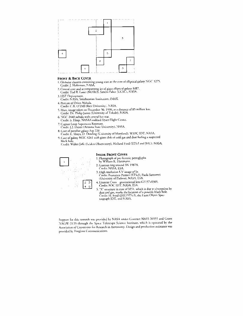
...............................i.......i.......r-1.......................3
FRONT & BACK COVER
1. Globular clusters containing young stars at the core of elliptical galaxy NGC 1275.
Credit: J. Holtzmam NASA.
Central core and accompanying jet ofg ant elliptical galaxy M87.Credit: Tod R. Lauer (NOAO), Sandra Faber (UCSC), NAS .
3. HST Deployment.Credit: NASA, Smithsonian Institution, IMAX.
4. Portion of Orion Nebula.
Credit: C.R. O'Dell (Rice University), NASA.
5. Mars, image taken on December 30, 1990, at a distance of 85 million km.Credit: Dr. Philip James (University of Toledo), NASA.
6. NGC 2440 nebula with central hot star.
Credit: S. Heap, NASA/Goddard Space Flight Center.
7. Cygnus Loop Supernova Renmant.Credit: J.J. Hester (Arizona State University), NASA•
8. Core of peculiar galaxy Arp 220.Credit: E. Shaya, D. Dowling (University of Mary, land) WFPC IDT, NASA.
9. Core of galaxy NGC 4261 with giant disk of cold gas and dust fueling a suspectedblack hole.
Credit: Walter Jaffe (Leiden Observatory), Holland Ford (STScl and JHU), NASA.
INSIDE FRONT COVER
1. Photograph of pre-historic petroglyphsby William K. Hartmann.
2. Gaseous ring around SN 1987A.Credit: NASA, ESA.
3. High resolution UV image oflo.Credit: Francesco Paresce (STScI), Paola Sartoretti
(University' of Padova), NASA, ESA.
4. Einstein Cross_ravitational lens G2237+0305.Credit: FOC IDT, NASA, ESA.
5. "X" structure in core of M51, which is due m absorption bydust and gas, marks the location of a possible black nole.Credit: H. Ford (JHU/STScl), the Faint Object Spec-
trograph IDT, and NASA.
Support for this research was provided by NASA under Contract NAS5-26555 and Grant
NAGW-3135 through the Space Telescope Science Institute, which is operated by the
Association of Universities for Research in Astronomy. Design and production assistance was
provided by Foxglove Communications.