Embed Size (px)
Citation preview

I E E E TRANSACTIONS ON MICROWAVE THEORY AND TECHNIQUES, VOL. 38, NO. 11, NOVEMBER 1990 1617
Theoretical Evaluation of Nonlinear Tapers for a High-Power Gyrotron
Abstract -In this paper the theoretical performance of two nonlinear circular waveguide tapers constructed for a LO GHz, 30 Mw amplifier utilizing the lowest circular electric mode is evaluated. Mode coupling is estimated with a code that solves the generalized telegraphist’s equa- tions numerically and is compared with the results of a cascaded scattering matrix code. It is found that assuming a sufficiently lossy conducting boundary allows evaluation of modes that pass through cutoff and that consideration of backward modes usually results in small changes in the forward modes that reconcile the two numerical procedures. A comparison of the raised cosine profile with other taper shapes is made.
I. INTRODUCTION ICROWAVE waveguides with varying cross sec- M tions have numerous applications, and the general
techniques for modeling the resultant mode conversion are well documented in the literature [1]-]5]. In high power source applications, for example, mode transducers are required when the desired mode is not practical (or convenient) for microwave production. Even when the desired mode is produced, mode competition and other considerations often demand waveguide dimensions that are incompatible with the heat load requirements of the beam dump or the electric field constraints on the output window. To meet these constraints, a slowly varying wave- guide cross section after the interaction circuit is usually favored over a discrete transition because of transmission and mode purity considerations. Limitations on physical length and mode conversion usually dictate careful design of the taper profile.
In this paper we describe the output waveguide of a 10 GHz, 30 MW gyroklystron [61, [71 designed to operate in the TE,,, mode. High mode purity is required to maximize load efficiency and minimize peak electric fields. Con- straints on the microwave interaction, the beam dump, and the output window combine to require two separate tapers. The first has an initial radius which supports only the TE,,, mode (at 10 GHz) and a final radius which also supports the TE,,* mode. The second taper also supports the TE,,, mode at the large end (see Fig. 1).
To evaluate the performance of these tapers, we have developed a code which starts with Solymar’s approach [1]
Manuscript received August 10, 1989; revised July 11, 1990. This work
The author is with the Laboratory for Plasma Research, University of
IEEE Log Number 9038704.
was supported by the US . Department of Energy.
Maryland, College Park, MD 20742.
‘ 0 8 8
01 ‘ a . - l l . * I . I . * . . I * . . * ’ * * * * I * ’ . ’ .
0 .05 .IO .I5 .20 .25 30 .35 Axial Distance (m)
Fig. 1. The raised cosine profile of the large taper.
to solving the generalized telegraphist’s equations by uti- lizing forward and backward waves and extends it to modes that go through cutoff in the taper. In the next section we describe this procedure in detail and discuss the validity of the code. In Section 111 we present the design of our tapers and detail the performance predic- tions. In Section IV we discuss other possible taper pro- files. The findings of this study are summarized in the final section.
11. SOLUTION METHOD
We consider only circular cylindrical tapers where the wall radius a(z) is a smoothly varying function of z . The rectangular case is similar. Solymar’s method [ 13 involves solving the first-order differential equation
a 2 - - ( K”- 7) . A _-
dz
where the amplitude vector A-is
and A : represents the first forward wave amplitude, A ; represents the first backward wave amplitude, etc.
0018-9480/90/1100- 1617$01 .OO 01990 IEEE
~- ~~
1618 IEEE TRANSACTIONS ON MICROWAVE THEORY AND TECHNIOUES, VOL. 38, NO. 11, NOVEMBER 1990
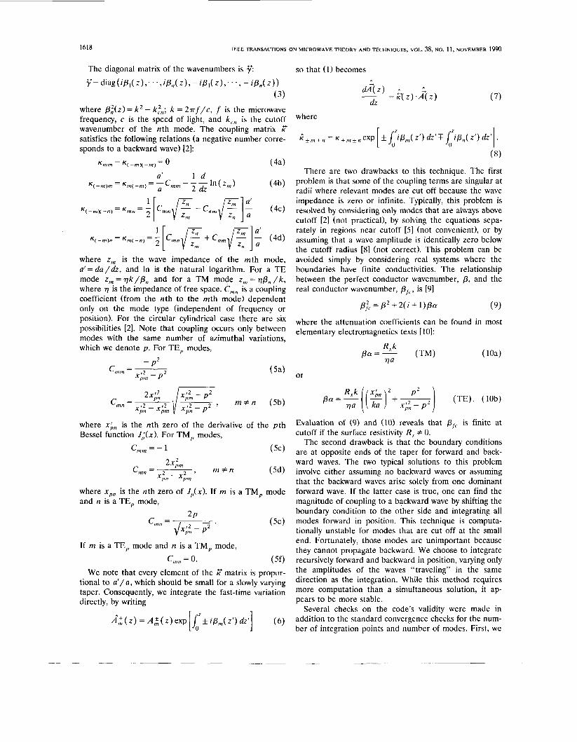
The diagonal matrix of the wavenumbers is r”: r”= diag(iP,( z ) , * * . , i P , , ( z ) , - ip , ( 2);. . , - iplI( 2))
(3) where p,’(z>= k 2 - k:,; k = 2 7 r f / c , f is the microwave frequency, c is the speed of light, and k, , is the cutoff wavenumber of the nth mode. The coupling matrix I7 satisfies the following relations (a negative number corre- sponds to a backward wave) [2]:
K,, = K( -,x -,) = 0 (4a)
where z, is the wave impedance of the mth mode, a’= d a / d z , and In is the natural logarithm. For a TE mode z , = q k / p , and for a TM mode z , = qp, / k , where 77 is the impedance of free space. C,, is a coupling coefficient (from the nth to the mth mode) dependent only on the mode type (independent of frequency or position). For the circular cylindrical case there are six possibilities [2] . Note that coupling occurs only between modes with the same number of azimuthal variations, which we denote p . For TE, modes,
- P 2 $5, - P 2
Cmm = ~ (5a)
where x;,, is the nth zero of the derivative of the p th Bessel function J;(x) . For TM, modes,
where x,, is the nth zero of J,(x) . If m is a TM, mode and n is a TE, mode,
If m is a TE, mode and n is a TM, mode,
c,,, = 0. ( 5 0 We note that every element of the I7 matrix is propor-
tional to a ‘ / a , which should be small for a slowly varying taper. Consequently, we integrate the fast-time variation directly, by writing
so that (1) becomes
U&) ,. -- - F( 2) *A( 2 )
dz (7)
There are two drawbacks to this technique. The first problem is that some of the coupling terms are singular at radii where relevant modes are cut off because the wave impedance is zero or infinite. Typically, this problem is resolved by considering only modes that are always above cutoff [2] (not practical), by solving the equations sepa- rately in regions near cutoff [5] (not convenient), or by assuming that a wave amplitude is identically zero below the cutoff radius [81 (not correct). This problem can be avoided simply by considering real systems where the boundaries have finite conductivities. The relationship between the perfect conductor wavenumber, p, and the real conductor wavenumber, pf,, is [91
(9) p;c = p2 + 2 ( i + 1)pa
where the attenuation coefficients can be found in most elementary electromagnetics texts [ l o ] :
pa=-- R s k (TM) 77a
or
Evaluation of ( 9 ) and (10) reveals that pfc is finite at cutoff if the surface resistivity R s f 0.
The second drawback is that the boundary conditions are at opposite ends of the taper for forward and back- ward waves. The two typical solutions to this problem involve either assuming no backward waves or assuming that the backward waves arise solely from one dominant forward wave. If the latter case is true, one can find the magnitude of coupling to a backward wave by shifting the boundary condition to the other side and integrating all modes forward in position. This technique is computa- tionally unstable for modes that are cut off at the small end. Fortunately, those modes are unimportant because they cannot propagate backward. We choose to integrate recursively forward and backward in position, varying only the amplitudes of the waves “traveling” in the same direction as the integration. While this method requires more computation than a simultaneous solution, it ap- pears to be more stable.
Several checks on the code’s validity were made in addition to the standard convergence checks for the num- ber of integration points and number of modes. First, we

LAWSON: THEORETICAI. FVAI UATION OF NONLINFAR TAPERS
Small Taper
0.02600
0.03571
0.19456
0.05715
0.02924
7 .O
0.367
0.354
1619
Large Taper
0.03571
0.06350
0.30480
0.07620
0.04150
12.0
0.450
0.150
checked for conservation of energy. For convenience, we always assume one injected mode, which we denote AL(0). If the length of the taper is z,,, energy is conserved if
0.00336
0.03013
0.03699
0.16443
IA,:(0)12= ( I A r ( 0 ) l 2 + I A ~ ( z , . ) l Z ) . (11)
0.05899
0.12091
0.11790
0.33246
j = I
This expression neglects resistive losses, which are usually small for short tapers made from good conductors. When we assume that only forward wave amplitudes are nonzero, energy is conserved typically to within f 2%. The discrep- ancy lies mainly in the final amplitude of the injected wave. When the backward waves are added, energy is conserved to a small fraction of a percent. Convergence in the forward/backward integration scheme is checked as well. When a surface resistivity corresponding to copper is assumed, all modes converge fairly well after two or three iterations, except for the modes which pass through cutoff in the taper. We have achieved convergences for these modes as well by assuming a more resistive material, such as 304 stainless steel [ll].
The code has also been checked against simple analytic predictions from the formulation that arises when it is assumed that there is only one parasitic mode and that the launched mode’s amplitude is constant. First, energy converted to one mode when a second mode is launched is approximately equal to the energy converted to the second mode when the first is launched. Also, when two modes are nowhere cut off, the transfer of energy from one mode to another is independent of launch direction (i.e., the end in which the wave is injected). Furthermore, when the launch mode is nowhere cut off but the parasitic mode passes through cutoff, a launch from either end results in the same parasitic power out the large end. Finally, when the launch mode is cut off, but the parasitic mode is not, the parasitic mode receives equal power in the forward and backward directions when the launch mode is injected in the large end of the taper.
The predictions of the code for the gyroklystron’s tapers are compared with the predictions of a scattering matrix code [12] in the next section. In Section IV, we compare our results briefly with the results published elsewhere.
111. NONLINEAR TAPER DESIGN The two gyroklystron tapers utilize a generalized “raised
cosine” profile which is described by
(12)
where rs and r,. are the starting and ending taper radii, respectively, z , is the taper length, zi is some specified intermediate point, and r , , rz , z I , z 2 , x , , and x2 are undetermined coefficients (see Fig. 1). Four of these unknowns are specified by demanding that r (z i ) = ri
TABLE I GYROKLYSTRON TAPER SPECIFICATIONS
and dr/dz(,,+ = tan 8,. The other two parameters are selected by minimizing mode conversion at some specified frequency. We have found that this profile gives superior results to simple cosine, hyperbolic tangent, parabolic [ 131, or arc/linear/arc profiles and is more convenient than other methods that parameterize the axial distance, such as the Dolph-Chebyshev tapers [41, [141.
The specifications of the two tapers are listed in Table I. Fig. 2 shows the resultant mode conversion in the small taper when the TE,,, mode is launched from the small end. Fig. 2(a) shows the conversion to the TE,,, forward wave as calculated by three different techniques. The solid line indicates the telegraphist’s solution when for- ward and backward waves are considered. The dotted line reveals the telegraphist’s solutions when the backward wave amplitudes are assumed to be zero. The dashed line shows the cascaded scattering matrix solution. To run the scattering code, the taper is divided into n constant-radius sections according to a scheme which limits the maximum change in radius and length in any given section. While there is no inherent limit to the number of sections used, n = 9 9 was chosen as the practical limit in terms of available memory and computation time. The latter curve is plotted only when the TE,, mode is above cutoff, which occurs at f = 9.37 GHz. Note that all solutions agree fairly well and so the quick approximate solution with no backward waves is probably an adequate design tech- nique. The largest discrepancy occurs just above cutoff, where the inclusion of backward waves helps to reconcile the two solutions. In some regions, the agreement be- tween the exact telegraphist’s solution and the scattering matrix code is so good that the dashed line is not visible. Fig. 2(b) reveals the power reflected in the TE,,, mode as calculated by three techniques. The exact telegraphist’s solution and the scattering matrix solution are the same as for the forward wave. The approximate backward solu- tion is found by assuming only an interaction with the injected wave, whose amplitude is held constant [2]. Even though the scattering matrix solution is not completely

1620 IEEE TRANSACTIONS ON MICROWAVE THEORY A N D TECHNIQUES, VOL. 38, NO. 11, NOVEMBER 1990
Exact Telegraphist's Solution
Scattering Matrix Solution ........... Approximate Teleqophist's Solution
1
INJECTED FREQUENCY (GHd
(a)
Exact Telegraphist's Solution ............ Approximate TeleqopMst's Solution ---P- Scottoring Matrix Solution t -
-mt
8 9 IO II 12 INJECTED FREQUENCY (GHd
(b) Fig. 2. Mode conversion in the small taper for an injected TE,,, mode
as a function of frequency: (a) the forward TE,,, wave; (b) the reflected TE,,, wave.
converged (this was checked by varying the number of regions), there is still relatively good agreement between solutions, and we can conclude that very little power is reflected in the desired frequency range (as expected). Finally, note that the circular electric modes do not convert to the TM,,, modes and that the reflected TE,,, wave is cut off in all of X-band.
Mode conversion to the forward waves when the TE, , wave is launched in the small taper is shown in Fig. 3. Again, the scattering matrix results are only plotted above cutoff, and agree well with the telegraphist's solution even when the power conversion is below 60 dB. The inflection
0 . . . . I " " I . ' . ' " " '
- Telegraphist's Solution - - - - - Scottering Matrix Solution
Y
TM,, -
INJECTED FREQUENCY (GHd Fig. 3. Parasitic forward wave amplitudes versus frequency at the exit
of the small taper due to an injected TE, , wave.
TABLE I1 MODE CONVERSION I N THE LARGE TAPER
I Injected Mode
-0.027 -48.05 -0.567
-47.64 -0.155 -18.26
-55.1 1 -36.77 -46.38
0 0 -10.48
0 0 -30.09
0 0 -54.32
-80.67 -71.68 -74.77
-71.68 -47.94 -92.93
0 0 -66.36
0 0 -60.67
10 GHz) - TEzi
-0.527
-39.22
-60.41
-79.78
-
-10.83
-38.06
-57.73
-67.70
-95.51
- -63.37
C -
-0.321
-29.75
-60.81
C
-16.29
-46.30
-66.08
-65.37
C
- -.56.13
C - In the parasitic mode identification TE,,,,,,, the n refers to the
azimuthal number; m = 1,2,3,4 refers to the radial mode number; and the f indicates a forward wave whereas the h indicates a backward wave. The relative power is given in dB. Cutoff modes are indicated by
point on the TE, , curve occurs where the TE,, backward mode reaches cutoff (at the small end).
Mode conversion in the large taper is displayed in Table I1 for various injected modes at 10 GHz. Though not listed, the results from the scattering matrix code were also computed and agreement with the telegraphist's solution was as good as for the small taper case. Note that the power loss in the injected mode is due both to mode

LAWSON: THEORETICAL EVALIJATION OF NONLINEAR TAPERS 1621
conversion and to the resistive waveguide. Also note that the reflected power is always small and that mode conver- sion decreases with the distance between cutoff wave- numbers, as expected.
IV. ALTERNATIVE TAPER PROFILES
In this section, the performance of the gyroklystron tapers is compared with that of three different taper profiles. The first is a linear taper with the axial variation of the radius given by r ( z ) = r , + ( r , - r , ) z / z , (all vari- ables are defined immediately after (12)). The second taper uses a simple cosine variation which obeys (12) with r , = ( r , - r T ) / 2 , x , = 0, and z , = z , = 7 2 , . The final taper is the modified Dolph-Chebyshev (D-C) taper [41, [141, which is parameterized by
and
where I,, is the modified Bessel function of the first kind of order zero, 1.51 < 8, and mode conversion from the mth to the nth radial mode is to be minimized at k (for a circular electric mode). The theoretical approximation for the D-C mode conversion is [2], [14]
(0.21723) (14) 1 8
sinh (8)
where the numerical factor comes from the first nonzero maximum of sin x /x.
The dominant concern for the small taper is mode conversion from the TE,,, to the forward TE,,2 mode. Consequently, the TE,,, amplitude for the four taper profiles is plotted in Fig. 4(a) as a function of frequency. All four tapers have r, = 0.02560, re = 0.03571, and z , =
0.19456. The choice of 8 = 8.39 for the D-C taper yields the same length as the other tapers for minimal mode conversion at 10 GHz. The hierarchy of suppression is as expected, with the linear taper being worst, followed by the simple cosine, the raised cosine (our design), and the D-C. For the small taper parameters W,,, = -69 dB at 10 GHz.
The TE,,, to TE,,2 mode conversion for the four pro- files with large taper parameters ( rs = 0.03571, re =
0.06350, and z , = 0.30480) is shown in Fig. 4(b). For the D-C taper, 8 = 5.07 was required, which yields an esti- mated conversion of W,,, = -38 dB at 10 GHz. This taper is more difficult to design than the smaller one because three or four modes are above cutoff (depending on the frequency) and because the increase in radius is
- -20- m 3
-
8 9 10 I I I2 INJECTED FREQUENCY (GHd od,
-60 t 12
-801 ' ' ' * ' . ' ' ' I ' ' * ' ' ' ' * ' 8 9 IO I I
INJECTED FREOUENCY ( G H d
(b) Fig. 4. Mode conversion from the TE,,, to the TE,,2 as a function of
frequency for several taper profiles with similar overall dimensions: (a) for the small taper; (b) for the large taper.
2.75 times as great, but the length is only 57% longer. The linear and simple cosine tapers perform as expected. The raised cosine profile is optimized at 10 GHz and outper- forms the modified D-C for over 1.5 GHz of bandwidth.
V. SUMMARY In this paper, resistive walls (in circular cylindrical
geometry) were included in the telegraphist's equations to stabilize the solution for modes that go through cutoff in the nonlinear taper. The resulting code was benchmarked against a cascaded scattering matrix code and agreed well over a wide range of parameters. The new code was faster
1622 IEEE TRANSACTIONS ON MICROWAVE THEORY AND TECHNIQUES, VOL. 38, NO. 11, NOVEMBER 1990
than the scattering matrix code, required less memory, had more rapid convergence for the backward modes, and
modes. It was shown that under Some conditions a raised
[61 K. R. Chu, V. L. Granatstein, P. E. Latham, W. Lawson, and C. D. Striffler, “A 30 MW gyroklystron amplifier design for high energy linear accelerators,” IEEE Trans. Plasma Sci., vol. PS-13,
W. Lawson et al., “Operating characteristics of a high power X-band gyroklystron,” in BEAMS ’90 Conf. Proc., to be published.
could rapidly find approximate results for the forward pp. 424-434, 1985. [71
cosine profile yields less mode conversion than the modi- fied DolPh-ChebYshev profile. TWO tapers with general-
[81 M, E. Read, private communication, [91 J. P. Jackson. Classical Electrodvnamics. New York: Wilev. 1975.
ized raised cosine profiles and a total length of approxi- mately o.5 GHz, 3o MW
p. 352. S. Ramo, J. R. Whinnery, and T. Van Duzer, Fields and Waces in Communication Electronics. New York Wiley, 1965, pp. 432-434. were designed for a [lo]
amplifier. These tapers increased the tube diameter from [ i l l R. C. Weast and M. J. Astle, CRC Handbook of Chemistry and approximately 2 inches to 5 inches while keeping the fornard power in parasitic mode below -47 dB and the reflected power below - 64 dB.
Physics. [I21 J. M. Neilson, P. E. Latham, M. Caplan, and W. Lawson, “De-
termination of the resonant frequencies in a complex cavity using the scattering matrix formulation,” IEEE Trans. Microwave Theory
Boca Raton: CRC Press, 1982, p. D-190
ACKNOWLEDGMENT Tech., vol. 37, pp. 1165-1170, 1989.
[13] J. L. Doane, “Parabolic tapers for overmoded waveguides,” in Proc. Eighth Int. Conf. Infrared and Millimeter Waves (Miami),
The author gratefully acknowledges many useful discus- sions - . with P. E. Latham, D. Welsh, J. Neilson, and M. E.
Dec. 1983. R. Hecken, “A near optimum matching section without disconti- nuities,” IEEE Trans. Microwave Theory Techniques, vol. MTT-20,
[14]
Kead. pp. 734-739, 1972.
REFERENCES L. Solymar, “Spurious mode generation in nonuniform wave- guides,” IRE Trans. Microwave Theory Tech., vol. MTT-7, pp.
F. Sporleder and H. G. Unger, Waveguide Tapers, Transitions, and Couplers. New York: Peter Peregrinus, 1974.
379-383, 1959.
J. L. Doane, “Mode converters f o r generating the HE,, mode from the TE,, in circular waveguide,” Int. J. Electron., vol. 53, pp. 573-586, 1982. H. Flugel and E. Kuhn, “Computer-aided analysis and design of circular waveguide tapers,” IEEE Trans. Microwace Theory Tech., vol. 36, pp. 332-336, 1988. W. A. Huting and K. J. Webb, “Numerical solution of the continu- ous waveguide transition problem,” IEEE Trans. Microwave The- ory Tech., to be published.
Wesley G. Lawson (S’84-M’85) received the B.S. degree in mathematics and the B.S., M.S., and Ph.D. degrees in electrical engineering from the University of Maryland, College Park.
He worked four years at Harry Diamond Lab- oratories on electronics and has worked eight years on various fast-wave microwave sources at the University of Maryland’s Charged Particle Beam Laboratory, where he is currently an As- sistant Professor.