Embed Size (px)
Citation preview
International Journal of Scientific & Engineering Research Volume 4,Issue 6, June 2013 ISSN 2229‐5518
Theoretical Steady-state Forced Flow Boiling Evaporator for Double-tube Thermosyphon
(FFDTT)
Loula A. Shouman, M. Abd El-Aziz, Adel Alyan
Atomic Energy Authority, Reactors Department, 13759 Cairo, Egypt [email protected]
Abstract: A mathematical model has been developed for the new type of the thermosyphon, in order to describe thermal behavior of the forced flow boiling double-tube thermosyphon in steady state operation. The present work of theoretical forced flow boiling inside the evaporator of the double-tube thermosyphon is described in a mathematical model in one dimensional flow. The model is describing both thermal and phase flow of the forced flow double tube thermosyphon (FFDTT). A computer program is designed to solve the presented model to estimate the performance of the thermosyphon. The current model can predict the behavior of a forced flow boiling double- tube closed two-phase thermosyphon, at different operating conditions Analysis of the thermosyphon response to various operating conditions has been performed.
Index Terms— Forced Flow Boiling; Double-tube closed-thermosyphon; steady-state; Theoretical investigation; Model; Analytical Solution.
—————————— —————————— 1. I TRODUCTION N
he conventional thermosyphon is typically made by drawing a vacuum on an air-tight vessel, then a controlled amount of working fluid, charged into the vessel [1].
When heat added at the bottom of thermosyphon, the liquid vaporizes and rises to the top of the vessel due to buoyancy effect and liquid runs down the walls to the bottom of the thermosyphon, due to gravity [2]. While the double tube thermosyphon (DTT) is a conventional closed two-phase thermosyphon with an inserted inner tube in the evaporator section. In the double tube thermosyphon, the inner tube divides the liquid pool in the evaporator into two regions: an inner cylinder (down comer) and an annular channel. When the heat added to the outer tube of the evaporator, liquid in the annular gap is heated to saturation and ultimately boils. Vapor-liquid flow is formed in the annular gap flows upwards along the gap to the top of the inner-tube. Since there is two-phase in the annular gap and one phase liquid is in the inner tube, down comer, forced circulation by the pump causes the liquid in inner tube to flow from the bottom of the tube to the annular gap. This process produces an inner forced annular circulation of the working fluid inside the evaporator section. Since the latent heat of evaporation is high, the wickless heat pipe can transport considerable quantities of heat over considerable distance with a very small temperature drop [3]. The flow boiling in double tube thermosyphon is due to the natural circulation of fluid. The natural circulation is started when the heat added in the riser and a density difference is occurred between the riser and down comer. At this investigation a new type of forced flow boiling inside the evaporator of thermosyphon (FFDTT) has been developed by using a pump to circulate the fluid. The theoretical investigations were performed to study the response of a water thermosyphon to abrupt changes in input power,
different forced flow rates at evaporator length. 2- The model A mathematical model is in one dimensional flow simulate the steady-state performance and the operational characteristics of the gravity-assisted forced flow two-phase closed thermosyphon with double-tube evaporator in the vertical orientation FFDTT. The model is considerably simplified to reduce the processing computer time as much as possible, which consider the lumped analytical and numerical models, which require long computational time. Therefore, the model is primarily based on the relation of heat transfer by convection and conduction in each section of double tube thermosyphon. Then, the temperature profile for the wall and working fluid is accurately determined by the proposed model. The current model can predict the behavior of the forced flow double tube- closed two-phase thermosyphon, at different operating conditions. 2-1 Model description and assumptions Fig. (1) illustrates the geometry and dimensions of the thermosyphon main tube made of copper with 32 mm inner diameter, 1.5mm thickness and 1000 mm long. The evaporator and condenser section lengths are 600 mm and 250 mm respectively, while the adiabatic section is 150 mm long. Inner tube installed inside the evaporator. The inner tube has 600 mm lengths. This structure forms a hot channel, where the forced flowing liquid circulated between inner and outer tubes [4,5,6,7,8]. The evaporator section was uniformly heated and the heat source is simulated directed to the outer wall of the evaporator section. While the condenser section was convectively cooled, using cooling water at ambient temperature and constant pressure at 0.05 MPa, the forced flow boiling two-phase closed thermosyphon with double-
T
IJSER © 2013 http://www.ijser.org
2646
IJSER
International Journal of Scientific & Engineering Research Volume 4,Issue 6, June 2013 ISSN 2229‐5518
tube evaporator (FFDTT) is basically divided axially into three basic regions: evaporator (heating), adiabatic (thermally shielded) and condenser (cooling) sections. Individually, each region is mathematically and thermally treated due to variation of the heat transfer processes. In addition, the evaporator region is sub-divided into two main regions: a liquid pool and a liquid film region. The heat transfer regimes are completely different for the two regions and consequently, the pertinent heat transfer coefficients. The model is analyzed in one-dimension, where the axial coordinate x is mainly measured from the evaporator bottom. To facilitate the current analysis, the present numerical steady-state model has considered the following assumptions:
IJSER © 2013 http://www.ijser.org
1. One-dimensional flow for both vapor and liquid in the axial direction.
2. Isoflux heating, i.e uniform radial heat flux of heating and cooling processes in the evaporator and condenser sections.
3. The vapor superheat is very small; therefore the vapor is taken at the saturated conditions.
4. The condensate calculation is considered at the saturation temperature, thus sub-cooling is neglected.
5. The pressure drop in the liquid film and vapor core is considered negligible.
6. Axial conduction through the adiabatic wall is negligible.
7. Conduction and convection heat transfer at the liquid-vapor interface are considered very small.
8. Saturation vapor temperature in the adiabatic section equals that of liquid-wall interface at the exit of the evaporator.
2.2 Mathematical Modeling A one-dimensional, steady state flow model is presented for the water/copper forced flow double-tube thermosyphon. This model is proposed to predict the local liquid and thermosyphon wall temperature distribution. For the present model, the most controlling parameters considered are the sub cooling flow rate at the bottom end of the evaporator, and the heat transfer rate (thermal load). Once, the values of these parameters are predetermined, and then the local external wall, liquid and vapor temperature can be readily calculated. The heat transfer through the working fluid and thermosyphon wall is treated as a semi-conductor and is characterized by a thermal resistance, defined in the following relation. Therefore, the local temperature of any semi-conductor is primarily dependent on the local thermal resistance. But, the thermal resistance is inversely proportional to the thermal conductivity of wall material, or the convective heat transfer coefficient through the working fluid. Alternatively, the heat transfer coefficient is commonly related to the thermohydraulic characteristics of flow. Thus, each section of the thermosyphon is separately treated, as the heat transfer regime differ from one section to the other.
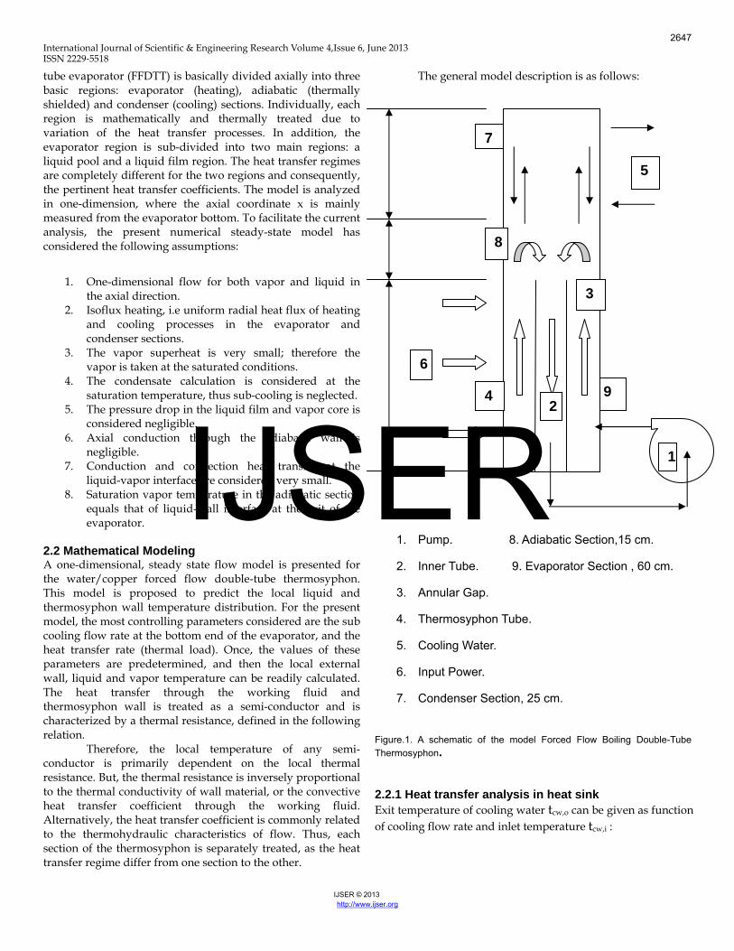
The general model description is as follows:
1. Pump. 8. Adiabatic Section,15 cm.
2. Inner Tube. 9. Evaporator Section , 60 cm.
3. Annular Gap.
4. Thermosyphon Tube.
5. Cooling Water.
6. Input Power.
7. Condenser Section, 25 cm.
Figure.1. A schematic of the model Forced Flow Boiling Double-Tube Thermosyphon.
2.2.1 Heat transfer analysis in heat sink Exit temperature of cooling water tcw,o can be given as function of cooling flow rate and inlet temperature tcw,i :
9
7
1
2
6
4
5
3
8
2647
IJSER
International Journal of Scientific & Engineering Research Volume 4,Issue 6, June 2013 ISSN 2229‐5518
icw
cwpcwocw t
cm
Qt ,,*. += (1)
Where, the temperature difference across the heat calorimeter is: ∆t cw=t cw,o-t cw,i (2)
owccw
CcwT t
hq
,+= (3)
The average heat transfer coefficient for forced convection, between the condenser surface and cooling water can be calculated in the case of laminar and turbulent flow regimes [9] respectively as:
hcw=1.86(Re Pr)cw
0.33(dh/Lc)0.33(µcw/µ)0.14(kcw/dh) for laminar (4) hcw =0.023(Re cw )0.8 (Pr cw)0.33 (kcw/dh) for turbulent (5) The hydraulic diameter dh for the annulus area of cooling jacket The flow is assumed as turbulent at Recw ≥ 3000, or laminar at Recw < 3000, also all physical properties are evaluated at a mean temperature equal to the average between the mean wall temperature and the bulk cooling temperature, Recw = 4m.
cw / π * dh * µcw (6) As a good approximation, all properties are evaluated at the exit temperature of cooling water tcw,o . 2.2.2 Heat transfer in condenser section (wall, falling film &vapor)
As the convective heat transfer coefficient hcw was determined, the outer condenser wall temperature twc,o is evaluated as:
Furthermore, the local inner condenser wall temperature tcw,i is determined by mean of the heat transfer by conduction through the wall. Then, the vapor temperature in the condenser can be calculated as:
The falling condensate film flow inside thermosyphon
surface is assumed as laminar flow and the film was thin with respect to the radius of curvature. Therefore, the simplified Nusselt’s film condensation theory for vertical flat plate was adopted for condensation in the thermosyphon condenser [10]. The local heat transfer of condensation is given as:
fcocviwc hA
QTT,
, −= (7)
cwiwcowc Lk
ddQLogTT io
π2)(
,, −= (8)
3/1231
34
)/(][Re)
34(
gkh
l
lcfcf ν
−
= (9)
heat transfer of condensation is given as:
Where Recf is the local Reynolds number of the falling condensate film, and qc,i is the heat flux based on the inner condenser surface area.
3/1231
34
)/(][Re)
34(
gkh
l
lcfcf ν
−
= (10)
As heat energy is transferred through the condensate layer by conduction, thus, the temperature gradient could be assumed linear through the film. Therefore, the average condensate film temperature can be calculated as: tlc=(twc,i +tv)/2 (11) 2.2.3 Adiabatic section calculations
According to the assumption, the vapor temperature drop is neglected in the adiabatic section. Therefore, the vapor temperature in adiabatic is considered equal to the vapor temperature at the exit of the evaporator and the inlet to condenser sections. Owing to the thermal equilibrium between the vapor, falling liquid film and wall, the adiabatic wall and vapor temperatures is: twa = tv = tl (Le + La) (12) 2.2.4 Calculation of heat transfer coefficient
The heat energy is transferred to the fluid inside the annular riser through the outer tube wall. Heat transfer mechanism in riser based mainly on the forced flow pattern of fluid. Heat energy is transferred by convection in sub-section having single liquid phase, while heat is transferred by nucleate boiling coefficient for subsections having two-phase mixture flow. In condenser section, the heat transfer coefficient is by condensation. Also, the heat transfer coefficient is considered by convection for the cooling water in condenser jacket. 2.2.4.1 Single-phase sub cooled heat transfer coefficient
In sub cooled section the heat transfer coefficient between the sub cooled forced flowing liquid and tube wall is calculated from Dittus-Boelter correlation [11] for forced convection as following:
H
sbsbsb D
kNuh *= (13)
Where the Nussle number (Nu) is calculated by:
4.08.0 Pr*Re*023.0 sbsbsbNu = (14)
sb
Hsbsbsb
Duµ
ρ **Re = (15)
sb
sbpsbsb k
c*Pr
µ= (16)
Tsb,i=Tdc,0=Tv (17)
IJSER © 2013 http://www.ijser.org
2648
IJSER
International Journal of Scientific & Engineering Research Volume 4,Issue 6, June 2013 ISSN 2229‐5518
isbsb
sb TCpm
QT ,.0, *+= (18)
IJSER © 2013 http://www.ijser.org
sbsb
iwsb ThqT +=, (19)
iwsbsbw
sbowsb T
LkddLogQT io
,, 2)(*+=
π (20)
2.2.4.2 Two-phase flow heat transfer coefficient
For the forced flow boiling in the double tube thermosyphon (FFDTT), the flow boiling, is driven by the forced circulation inside the evaporator section, caused by the pump between the annulus and down-comer. In sub cooled and saturated boiling, various empirical correlations for the heat transfer coefficient in two-phase flow have been developed. In this model, the correlation proposed by Rohsenow and Chen [12] is considered a heat transfer coefficient of two-phase. This correlation propose that the flow boiling heat transfer actually results from the combination of pool boiling heat transfer and flow convective flow heat transfer as following:
FCNBTP hhh += (21) Where:
FZNB hsh *= (22) Where, s is the suppression factor and hFZ is the nucleate boiling heat transfer coefficient calculated from the Froster-Zuber equation [12].
24.029.024.05.0
79.049.045.075.024.0
***
*****00122.0
glfg
lllpsatsatFZ H
kcPTh
ρµσ
ρ∆∆= (23)
The convective part of the total heat transferred transfer is as:
lFC hFh *= (24) Where:
F: the two-phase heat transfer coefficient multiplier. hl: the single phase liquid convective heat transfer
coefficient calculated from Dittus-Boelter equation and is given as following:
H
lll D
kNuh *= (25)
The flow condition can be determined by the aid of the Reynolds number (Re) of the fluid, which is related to the mass flow rate of liquid:
4.08.0 Pr*Re*023.0 lllNu = (26)
l
Hl
µl
lDuxρ **)1(*Re −
= (27)
l
lpll k
c*Pr
µ= (28)
fg
b
Hm *=
Qx . (29)
)*/( fgHGqBo =
(30)
1.05..09..0
)(*)(*1
v
l
l
v
xxXtt
µµ
ρρ
⎥⎦⎤
⎢⎣⎡ −
= (31)
)86 (32) )1(*37.1())(*2400(1 .016.1
XttBoF ++=
⎥− ))(*)(Re*)10 217.16 F (33)
⎦
⎤⎢⎣
⎡+
=*15.1(1
1Sb
bTP
iwb ThqT +=, (34)
iwbowb tLk
t io
,, 2+=
π bw
ddQLog )( (35)
ips nd the theoretical results. Generally, the accurate prediction
por, liquid and wall, in the
n primarily starts at the heat sink point, and then recedes toward the condenser, adiabatic and evaporator
fly stat
2.
4. cf
3.1 Solution procedures The numerical, one-dimensional, steady state model is proposed to avoid the complex lumped modeling, as well as reducing the program computational time. The model primary depends on the basis of the previous empirical relationshaof axial temperatures of vathermosyphon sub-regions, is the main goal of this model. The solutiopsubsections. The procedures of solution sequence are brie
ed as:
1. Input the initial conditions: working fluid properties, thermosyphon dimensions, heat sink and source characteristics and the cooling parameters. Initialize the cooling Reynolds number, Recw and determine the flow regime (laminar or turbulent), then the average heat transfer coefficient, hcw is calculated between the cooling medium and the condenser wall.
3. As a first step, the local outer and inner wall temperature twc,o & twc,i are estimated along the condenser section. Assuming laminar falling condensate film and the local condensation heat transfer coefficient h is
2649
IJSER
International Journal of Scientific & Engineering Research Volume 4,Issue 6, June 2013 ISSN 2229‐5518
IJSER © 2013 http://www.ijser.org
5.
6. film in
7. ion of the hydrostatic head, is evaluated;
8.
oiling heat transfer coefficient formed the average evaporator heat transfer coefficient hep , con
rogram sequence that the present numerical solution is a straight forward calculation method
e less me and
an vapor quality are discussed. The results ere performed at normal operation of the thermosyphon,
ecified
and analyze the thermosyphon erformance. Also temperature distribution is necessary to
sfer coefficient. The same results of axial
mperature variation with distance is sharply attributed to e larg
calculated, and then the vapor temperature tv distribution is found in the axial direction of the condenser section. The vapor temperature in the adiabatic section is taken equal to that at the inlet to the condenser
section tv,Le+La , and due to the thermal equilibrium , the falling film is also taken at the same temperature twa,o. A continuous, smooth and laminar thin liquidthe evaporator is assumed, then the local evaporation heat transfer coefficient hef, and both inner and outer wall temperature, twef,i & twef,o are calculated. The local liquid pressure in the evaporator pool, plp, due to the actconsequently the corresponding saturation temperature distribution along the pool height tlp is determined. The local inner wall temperature twep,i in the liquid pool subsection, is found by calculating the local non boiling and b
sequently the outer wall temperature twep,o is determined.
It is clear from the p
without any iteration, which makes the program consumti proceeds quickly.
4. Discussion of the Analytical Modeling Results
The results of the analytical modeling are basically discussed and analyzed to evaluate the thermosyphon performance at the steady state operation of a closed two-phase double tube thermosyphon with forced convection at evaporator. This result analyzes the axial outer surface wall temperature distribution for all the thermosyphon sections. Also the effects of changing the transported thermal energy (heat rate) are conducted. The overall heat transfer coefficient, average evaporator heat transfer coefficient, effective thermal conductivity, vapor mass flow rate and the mean vapor temperature are presented. Also some parameters such as non-boiling, boiling regions along evaporator section, boiling and non-boiling heat transfer coefficient along evaporator section and the mewwithout occurrence of any limit in the previously spoperation ranges. 4.1 Axial Wall and Fluid Temperature Distribution The results were conducted at steady state operation to measure the local outside wall surface and vapor temperature distribution. These measures are of great significance to interpret the results p
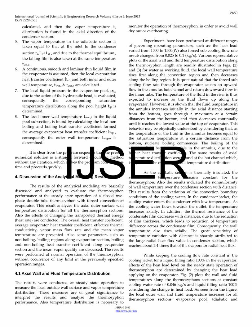
monitor the operation of thermosyphon, in order to avoid wall dry out or overheating. Experiments have been performed at different ranges of governing operating parameters, such as: the heat load varied from 1000 to 1500(W) also forced sub cooling flow rate m.sub changed from 0.025 to 0.1 (kg/s). Various representative plots of the axial wall and fluid temperature distribution along the thermosyphon length are readily illustrated in Figs. (2) and (3) for water as working fluid. the local wall temperature rises first along the convection region and then decreases along the boiling region. It is quite natural that the forced sub cooling flow rate through the evaporator causes an upward flow in the annulus hot channel and return downward flow in the inner tube. The temperature of the fluid in the riser is thus expected to increase as the fluid flows up along the evaporator. However, it is shown that the fluid temperature in the annulus increases initially in the axial distance starting from the bottom, goes through a maximum at a certain distances from the bottom, and then decreases continually until it reaches the lowest value at the top of evaporator. This behavior may be physically understood by considering that, as the temperature of the fluid in the annulus becomes equal to the saturation temperature at a certain distance from the bottom, nucleate boiling commences. The boiling of the working fluid becomes possible in the annulus, due to the higher heat trantemperature distribution were found at the hot channel which, is agree with the evaporator wall temperature distribution. As the adiabatic section is thermally insulated, the surface wall temperature remains constant for the thermosyphon. Also the results indicated the nonuniformity of wall temperature over the condenser section with distance. This results from the variation of the convection boundary conditions of the cooling water. In the condenser jacket, the cooling water enters the condenser with low temperature. As the cooling water flows towards the outlet, the temperature increases axially. In addition, the thermal resistance of the condensate film decreases with distances, due to the reduction of film thickness, which leads to reduction of temperature difference across the condensate film. Consequently, the wall temperature also rises axially. The great sensitivity ofteth e radial heat flux value in condenser section, which reaches about 2.4 times that of the evaporator radial heat flux. While keeping the cooling flow rate constant in the cooling jacket for a liquid filling ratio 100% in the evaporator, effects of the heat load level on the steady state operation of thermosyphon are determined by changing the heat load applying on the evaporator. Fig. (2) plots the wall and fluid temperatures along the thermosyphons sections at constant cooling water rate of 0.046 kg/s and liquid filling ratio 100% considering the change in heat load. As seen from the figure, the local outer wall and fluid temperature increases for all thermosyphon sections: evaporator pool, adiabatic and
2650
IJSER
International Journal of Scientific & Engineering Research Volume 4,Issue 6, June 2013 ISSN 2229‐5518
IJSER © 2013 http://www.ijser.org
d temperature of the
at load and cooling flow rate.
s substantially concluded that at relatively high forced flow, the evaporator has a sub cooled hot channel (riser), while at lower forced flow the riser becomes fully saturated.
condenser, whenever the radial heat flow increases. Fig. (3) indicates that the axial local wall and fluiforced flow double tube thermosyphon decreased during increase in forced flow rate through the evaporator section at onstant hec
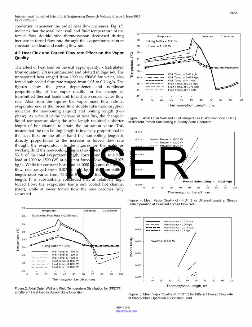
4.2 Heat Flux and Forced Flow rate Effect on the Vapor Quality The effect of heat load on the exit vapor quality, x (calculated from equation. 29) is summarized and plotted in Figs. 4-5. The transported heat ranged from 1000 to 1500W for water, also forced sub cooled flow rate ranged from 0.05 to 0.1 kg/s. The figures show the great dependence and nonlinear proportionality of the vapor quality on the change of transmitted thermal loads and forced sub cooled water flow rate. Also from the figures the vapor mass flow rate at evaporator end of the forced flow double tube thermosyphon indicates the non-boiling (liquid) and boiling length (two phase). As a result of the increase in heat flux, the change in liquid temperature along the tube length required a shorter length of hot channel to attain the saturation value. This means that the non-boiling length is inversely proportional to the heat flux; on the other hand the non-boiling length is directly proportional to the increase in forced flow rate thought the evaporator. In the Figures for the water as working fluid the non-boiling length ratio differs from 66 % to 53 % of the total evaporator length, corresponding to a heat load of 1000 to 1500 (W) at constant forced flow rate at 0.025 kg/s. While for constant heat load at 1000 (W) and the forced flow rate ranged from 0.025 to 0.1( kg/s) the non-boiling length ratio varies from 65% to 5% of the total evaporator length. It i
Thermosyphon Length at (cm).
0 10 20 30 40 50 60 70 80 90 100
Tem
pera
ture
, (o C
)
35
40
45
50
55
60
65
70
75
Wall Temp. at 1500 WWall Temp. at 1200 WWall Temp. at 1000 WFluid Temp. at 1500 WFluid Temp. at 1200 WFluid Temp. at 1000 W
Filling Ratio = 100%
Evaporator Adiabatic Condenser
Subcooling Flow Rate = 0.025 kg/s.
Figure.2. Axial Outer Wall and Fluid Temperature Distribution for (FFDTT) at different Heat load in Steady State Operation.
Thermosyphon Length, cm.
0 10 20 30 40 50 60 70 80 90 100
Tem
prat
ure,
(o C)
42
44
46
48
50
52
54
56
58
60
62
Wall Temp. at 0.05 kglsWall Temp. at 0.075 kglsWall Temp. at 0.1 kglsFluid Temp. at 0.05 kglsFluid Temp. at 0.075 kglsFluid Temp. at 0.1 kgls
Power = 1000 W
Evaporator Adiabatic Condenser
Filling Ratio = 100 %
Figure. 3. Axial Outer Wall and Fluid Temperature Distribution for (FFDTT) at different Forced Sub cooling in Steady State Operation.
Thermosyphon Length, cm.
0 10 20 30 40 50 60 70 80 90 100
Vap
or Q
ualit
y
0.000
0.002
0.004
0.006
0.008
0.010
0.012
0.014
Power = 1000 WPower = 1200 WPower = 1500 W
Forced Subcooling m.= 0.025 kg/s.
Figure. 4. Mean Vapor Quality of (FFDTT) for Different Loads at Steady State Operation at Constant Forced Flow rate.
Thermosyphon Length, cm.
0 10 20 30 40 50 60 70 80 90 100
Vapo
r Qua
lity
0.000
0.002
0.004
0.006
0.008
0.010
Mass flowrate = 0.025 kg/s.Mass flowrate = 0.05 kg/s.Mass flowrate = 0.075 kg/s.Mass flowrate = 0.1 kg/s.
Power = 1000 W
Figure. 5. Mean Vapor Quality of (FFDTT) for Different Forced Flow rate at Steady State Operation at Constant Load.
2651
IJSER
International Journal of Scientific & Engineering Research Volume 4,Issue 6, June 2013 ISSN 2229‐5518
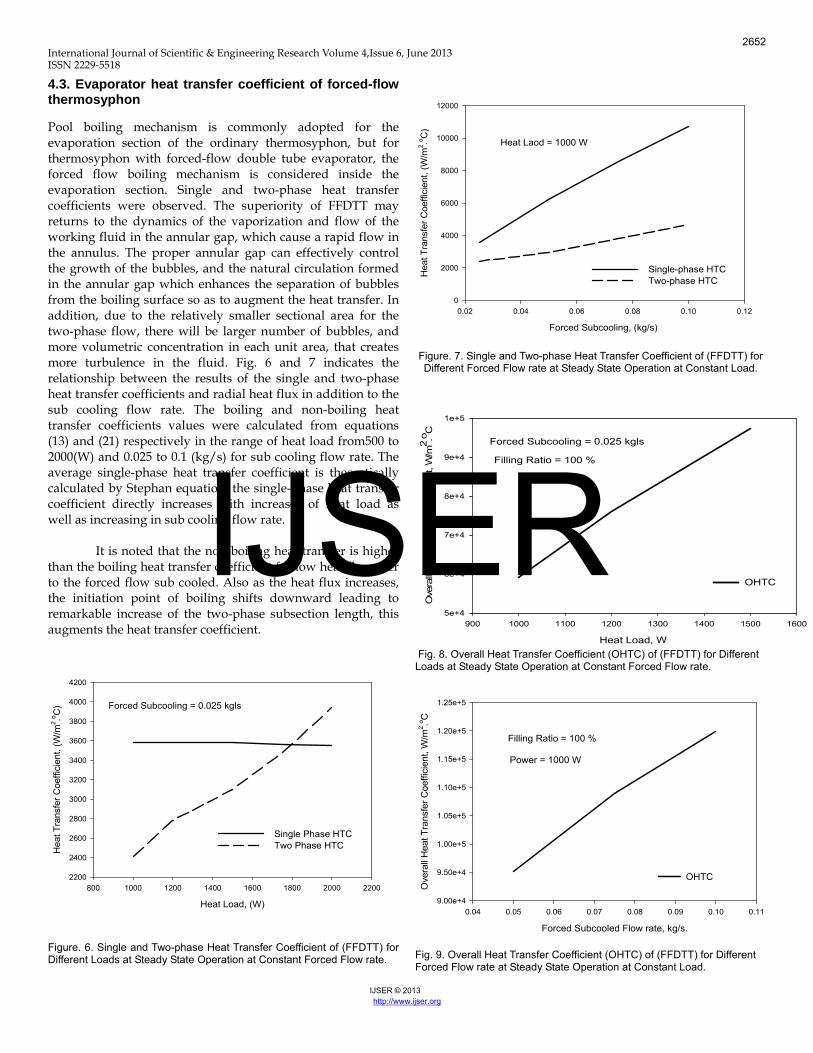
4.3. Evaporator heat transfer coefficient of forced-flow thermosyphon Pool boiling mechanism is commonly adopted for the evaporation section of the ordinary thermosyphon, but for thermosyphon with forced-flow double tube evaporator, the forced flow boiling mechanism is considered inside the evaporation section. Single and two-phase heat transfer coefficients were observed. The superiority of FFDTT may returns to the dynamics of the vaporization and flow of the working fluid in the annular gap, which cause a rapid flow in the annulus. The proper annular gap can effectively control the growth of the bubbles, and the natural circulation formed in the annular gap which enhances the separation of bubbles from the boiling surface so as to augment the heat transfer. In addition, due to the relatively smaller sectional area for the two-phase flow, there will be larger number of bubbles, and more volumetric concentration in each unit area, that creates more turbulence in the fluid. Fig. 6 and 7 indicates the relationship between the results of the single and two-phase heat transfer coefficients and radial heat flux in addition to the sub cooling flow rate. The boiling and non-boiling heat transfer coefficients values were calculated from equations (13) and (21) respectively in the range of heat load from500 to 2000(W) and 0.025 to 0.1 (kg/s) for sub cooling flow rate. The average single-phase heat transfer coefficient is theoretically calculated by Stephan equation, the single-phase heat transfer coefficient directly increases with increases of heat load as well as increasing in sub cooling flow rate. It is noted that the non-boiling heat transfer is higher than the boiling heat transfer coefficient for low heat flux refer to the forced flow sub cooled. Also as the heat flux increases, the initiation point of boiling shifts downward leading to remarkable increase of the two-phase subsection length, this augments the heat transfer coefficient.
Heat Load, (W)
800 1000 1200 1400 1600 1800 2000 2200
Hea
t Tra
nsfe
r Coe
ffici
ent,
(W/m
2 .o C)
2200
2400
2600
2800
3000
3200
3400
3600
3800
4000
4200
Single Phase HTCTwo Phase HTC
Forced Subcooling = 0.025 kgls
Figure. 6. Single and Two-phase Heat Transfer Coefficient of (FFDTT) for Different Loads at Steady State Operation at Constant Forced Flow rate.
Forced Subcooling, (kg/s)
0.02 0.04 0.06 0.08 0.10 0.12
Hea
t Tra
nsfe
r Coe
ffici
ent,
(W/m
2 .o C)
0
2000
4000
6000
8000
10000
12000
Single-phase HTC Two-phase HTC
Heat Laod = 1000 W
Figure. 7. Single and Two-phase Heat Transfer Coefficient of (FFDTT) for Different Forced Flow rate at Steady State Operation at Constant Load.
Heat Load, W
900 1000 1100 1200 1300 1400 1500 1600
Ove
rall
Hea
t Tra
nsfe
r Coe
ffici
ent,
W/m
2 .o C
5e+4
6e+4
7e+4
8e+4
9e+4
1e+5
OHTC
Forced Subcooling = 0.025 kgls
Filling Ratio = 100 %
Fig. 8. Overall Heat Transfer Coefficient (OHTC) of (FFDTT) for Different Loads at Steady State Operation at Constant Forced Flow rate.
Forced Subcooled Flow rate, kg/s.
0.04 0.05 0.06 0.07 0.08 0.09 0.10 0.11
Ove
rall
Hea
t Tra
nsfe
r Coe
ffici
ent,
W/m
2 .o C
9.00e+4
9.50e+4
1.00e+5
1.05e+5
1.10e+5
1.15e+5
1.20e+5
1.25e+5
OHTC
Power = 1000 W
Filling Ratio = 100 %
Fig. 9. Overall Heat Transfer Coefficient (OHTC) of (FFDTT) for Different Forced Flow rate at Steady State Operation at Constant Load.
IJSER © 2013 http://www.ijser.org
2652
IJSER
International Journal of Scientific & Engineering Research Volume 4,Issue 6, June 2013 ISSN 2229‐5518
Heat Load, W
900 1000 1100 1200 1300 1400 1500 1600
Effe
ctiv
e Th
erm
al C
ondu
ctiv
ity, W
/m.o C
30000
35000
40000
45000
50000
55000
60000
ETC
Forced Subcooling = 0.025 kglsFilling Ratio = 100 %
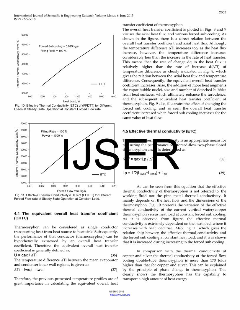
Fig. 10. Effective Thermal Conductivity (ETC) of (FFDTT) for Different Loads at Steady State Operation at Constant Forced Flow rate.
Forced Flow rate, kg/s.
0.04 0.05 0.06 0.07 0.08 0.09 0.10 0.11
Effe
ctiv
e Th
erm
al C
ondu
ctiv
ity, W
/m.o C
52000
54000
56000
58000
60000
62000
64000
66000
68000
70000
ETC
Filling Ratio = 100 %Power = 1000 W
Fig. 11. Effective Thermal Conductivity (ETC) of (FFDTT) for Different Forced Flow rate at Steady State Operation at Constant Load. 4.4 The equivalent overall heat transfer coefficient (OHTC) Thermosyphon can be considered as single conductor transporting heat from heat source to heat sink. Subsequently, the performance of that conductor (thermosayphon) can be hypothetically expressed by an overall heat transfer coefficient. Therefore, the equivalent overall heat transfer coefficient is generally defined as: U = qax / ∆Ti (36) The temperature difference ∆Ti between the mean evaporator and condenser inner wall regions, is given as: ∆Ti = twe,i – twc,i (37) Therefore, the previous presented temperature profiles are of great importance in calculating the equivalent overall heat
transfer coefficient of thermosyphon. The overall heat transfer coefficient is plotted in Figs. 8 and 9 viruses the axial heat flux, and various forced sub cooling. As shown in the figure, there is a direct relation between the overall heat transfer coefficient and axial heat flux. Although, the temperature difference ∆Ti increases too, as the heat flux increase, however, the temperature difference increases considerably less than the increase in the rate of heat transfer. This means that the rate of change dq in the heat flux is relatively higher than the rate of increase d(∆Ti) of temperature difference as clearly indicated in Fig. 8, which gives the relation between the axial heat flux and temperature difference. Consequently, the equivalent overall heat transfer coefficient increases. Also, the addition of more heat augments the vapor bubble nuclei, size and number of detached bubbles from heat surfaces, which ultimately enhance the turbulence, and the subsequent equivalent heat transfer coefficient of thermosyphon. Fig. 9 also, illustrates the effect of changing the forced sub cooling, and as seen the overall heat transfer coefficient increased when forced sub cooling increases for the same value of heat flow. 4.5 Effective thermal conductivity (ETC) The effective thermal conductivity is an appropriate means for measuring the performance of a forced-flow two-phase closed thermosyphon and it is determined as: Keff = qax*Lp / ∆Ti (38) Lp = 1/2(Levap+Lcond) + Lad (39)
As can be seen from this equation that the effective thermal conductivity of thermosyphon is not referred to, the working fluid nor the pipe metal thermal conductivity. It mainly depends on the heat flow and the dimensions of the thermosyphon. Fig. 10 presents the variation of the effective thermal conductivity of the current vertical water/copper thermosyphon versus heat load at constant forced sub cooling. As it is observed from figure, the effective thermal conductivity is extremely dependent on the heat load, where it increases with heat load rise. Also, Fig. 11 which gives the relation ship between the effective thermal conductivity and the forced sub cooling at constant heat load, and it was shown that it is increased during increasing in the forced sub cooling.
In comparison with the thermal conductivity of copper and silver the thermal conductivity of the forced flow boiling double-tube thermosyphon is more than 170 folds higher than that for copper and silver. This can be explained by the principle of phase change in thermosyphon. This clearly shows the thermosyphon has the capability to transport a high amount of heat energy.
IJSER © 2013 http://www.ijser.org
2653
IJSER
International Journal of Scientific & Engineering Research Volume 4,Issue 6, June 2013 ISSN 2229‐5518
IJSER © 2013 http://www.ijser.org
5. Conclusion A mathematical model has been developed for forced flow double-tube closed two-phase thermosyphon, in order to convert pool boiling to forced flow boiling mechanism inside thermosyphon in addition to describe thermal behavior in steady-state regime. An influence analysis of the thermosyphon response to various operating conditions has been performed. It has been shown that the model developed in this work can be used as an efficient tool in designing thermosyphons. The current of the derived mathematical model accurately predict the local wall and fluid temperature, evaporator heat transfer coefficients, the overall heat transfer coefficient as well as the lengths of the non-boiling and boiling region also the vapor quality. It was found that the single phase heat transfer coefficient is higher than the two-phase heat transfer coefficient refer to the forced sub cooling. NOMENCLATURE: A area,(m2). cp specific heat, (J/kg. oC). d diameter, (m). dh hydraulic diameter, (m). g acceleration of gravity,(9.81 m/s2). h heat transfer coefficient, (W/ m2. oC). hfg latent heat of vaporization, (j/kg. oC). k thermal conductivity,(W/m. oC). keff effective thermal conductivity,(W/m. oC). L length, (m). m. water flow rate, (kg/s). P pressure, (N/ m2 ). q heat flux, (W/ m2). Q heat load,(W). t temperature,( oC). ∆T temperature difference,( oC). u overall heat transfer coefficient,(W/ m2. oC). Ueq equivalent overall heat transfer coefficient(W/m2 oC). x Axial distance, (m). Greek Symbols α void fraction. ε configuration (geometry) factor. µ dynamic viscosity,(N.s/ m2). β thermal expansion coefficient(K-1) ν kinematic viscosity,( m2/s). ρ density,(kg/m3). σ surface tension,(N/m).
Dimensionless Groups Pr Prandtl number, (Cp µ/k). Ra Raighly number, (βgdi4qe/klαlνl). Re Reynolds number, (4q L/hfg µ). Subscripts a adiabatic, am ambient, ax axial, c condenser, cw cooling water e evaporator, eq equivalent, f film, I,i inner, initial, j jacket, l liquid o outer, m mean, nc natural convection, p pool, r radial, sat saturation, tp two-phase v vapor, w wall.
REFERENCES [1] Calvin. C Silverstein, “Design and Technology of Heat Pipes for Cooling and Heat Exchange”, Hemisphere Publishing Corporation, Washington (U.S.A.), 1992. [2] G. P. Peterson, “An Introduction to Heat Pipes-Modeling, Testing and Applications”, John Wiely & Sons, Inc. New York (U.S.A.), 1994. [3] D.A. Reay and P.A. Kew "heat pipes, theory, design and applications" Linacre House, Jordan Hill, Oxford OX2 8 DP Fifth edition 2006. [4] M. A. Abd_Rabo, Saadawy M. S.,K. Khodairy and A. K. abd El_Aziem "Transient Performance of Thermosyphon" Al-Azhar University Engineering Journal, JAUES Vol. 5, No. 2, Dec. 2010 p339-348 [5] Kamel, M.Shamloul, M. Sadaawy, and A. Zoklot, "Thermal Characteristics of The Closed Two-phase Thermosyphon With Inner Tube", M.Sc. thesis, Zagazig University, 2006.
2654
IJSER
International Journal of Scientific & Engineering Research Volume 4,Issue 6, June 2013 ISSN 2229‐5518
IJSER © 2013 http://www.ijser.org
[6] M. S. Saadawy, M.M. Abo El-Nasr and M. Abd El-Aziz., "Feasibility of The New Type- The Closed Two-Phase Double Tube Thermosyphon ( CTP- DTT): Performance Study ", Sci. Bull. Fac. Eng. Ain Shams Univ., Vol.39, No.3, PP.923-939, Sept. 2004. [7] M. S. Saadawy, M.M. Abo El-Nasr and M. Abd El-Aziz, "Investigation of boiling Heat Transfer Characteristics of Double-Tube Thermosyphon (DTT) ", 13th International Heat Pipe Conference 13th Int. Heat Pipe Confer. Shangai, Chaina, PP.333-342, September 21-25, 2004. [8] Lanchao Lin and Amir Faghri "An Analysis of Two-phase Flow Stability in a Thermosyphon with Tube Separator" Department of Mechanical Engineering, University of Connecticut, Storrs. CT 06260-3139. U.S.A. May 1997. [9] Frank P. Incropera and David P Dewitt,” Introduction of heat transfer “John Willy & Sons, Inc., New York, 1985. [10] M.Shiriashi,K.Kikuchi and T.Yamanishi, ”Investigation of heat transfer characteristics of a two-phase closed thermosyphon”, 4th International heat pipe conference, London (UK),1981. [11] P.B. Whalley “Boiling Condensation and Gas-Liquid Flow” Department of Engineering Science, University of Oxford 1989. [12] C. Xiang, Q. Zhang and M. Tongze “Natural convection boiling heat transfer in a two-phase closed thermosyphon”, proc. 8th Int. heat pipe conf., Beijing, China (1992) p 170-175. [13] Gungor,K.E, Winterton,R.H.S.(1987) Simplified general correlation.
2655
IJSER