Embed Size (px)
Citation preview
56
Journal of University of Thi-Qar No.3 Vol.2 Dec/2006
Theoretical Study for Plate with Holes Under Distributed Load Using Finite Element Method
Sadiq Muhsin Ihmood Mohammed Ewaish Hazim Ismaeel Mech.Eng. Dept Civil Eng. Dept Mech.Eng. Dept College Of Engineering College Of Engineering College Of Engineering Thi Qar University Thi Qar University Thi Qar University
Abstract The study represents a numerical investigation onto the behavior of a plate with hole, or number of holes by finite element method. The investigated specimens are subjected to a direct tension stresses acting parallel to the axis of the plate. Initially the plate contain one hole at the center of plate, the diameter of this hole was changed to study the effect of this variation on stress concentration. Also , the effect of number of holes onto the stress concentration were studied by taken a plate with one hole, two holes, three holes and four holes distributed along the plate axis. In each study all the holes had the same diameter. Finally the effect of the distance between the centers of holes were studied by taken a plate with four holes at the same distance each other, then these distances varied uniformly. All results were obtained using a program called ANSYS.
الخالصة
وع ن ن اذج م رف نم لوك وتص ول س ة ح ة نظری ث دراس ذا البح دم ھ تخدام (Plate With Holes)یق باس . (Finite Element Method)طریقة العناصر المحددة
ي ع ف ى ثقب یق وي عل ول وتحت اه الط د باتج ى اجھادات ش النماذج المستخدمة في ھذه الدراسة كانت معرضة إلفیحة ز الص ادات.مرك ز االجھ ى تمرك ر عل ذا التغیی أثیر ھ ة ت ب لدراس ر الثق ر قط م تغیی Stress)ت
Concentrations) وب دد من الثق ى ع وي عل ذ صفائح تحت ق أخ ز االجھادات عن طری ى تمرك أیضا تم دراسة تأثیر عدد الثقوب عل
أربع ثقوب مع تغ را صفیحة ب ثالث ثقوب وأخی م ب ین ث رى بثقب د وأخ رة بثقب واح ة م ذه الثقوب لمعرف ر أقطار ھ یی .السلوك تحت ھذه التغییرات
ى وي عل ذ صفیحة تحت ق أخ ز االجھادات عن طری ى تمرك وأخیرا تم دراسة تأثیر المسافة بین مراكز الثقوب عل .ثم تغییر ھذه المسافات مع المحافظة على تساویھا بین الثقوب،أربع ثقوب وعلى مسافات متساویة
مى النتائج امج یس ق استخدام برن ل بواسطة ANSYSتم الحصول علیھا عن طری امج متخصص للح وھو برن .العناصر المحددة
57
Journal of University of Thi-Qar No.3 Vol.2 Dec/2006
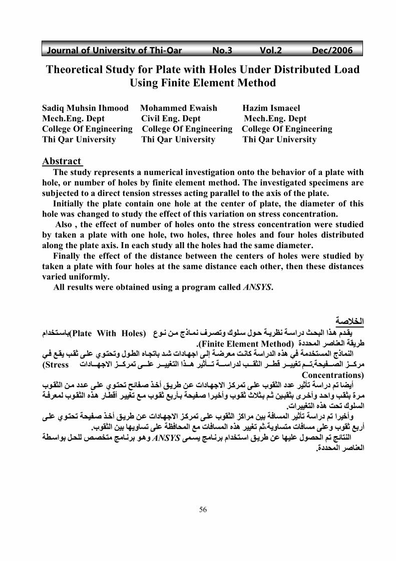
Introduction A thin planar body subjected to plane loading on its edge surfaces said to be in plane stresses. here stresses z ,xz , and yz are set as zero [3]. For plane stress situations, assuming isotropic materials, Which is used as =D In engineering practice, the actual stress distribution does not have to be determined. Instead, only the maximum stress must be known, and the member is designed to resist this stress when the axial load P is applied. Stress concentration factor K is defined as a ratio of the maximum stress to the average stress acting at the smallest cross section, i.e., [5]
AP
avg
Where A is the smallest cross sectional area, section a-a in figure (1) Figure (1) Dimension of plate
xyxy
yxz
xyy
yxx
E
E
E
E
)1(2
)(
)(1
)(1
xy
y
x
xy
y
x E
2100
0101
1 2
avg
K max
a
a
t
w
hd
58
Journal of University of Thi-Qar No.3 Vol.2 Dec/2006
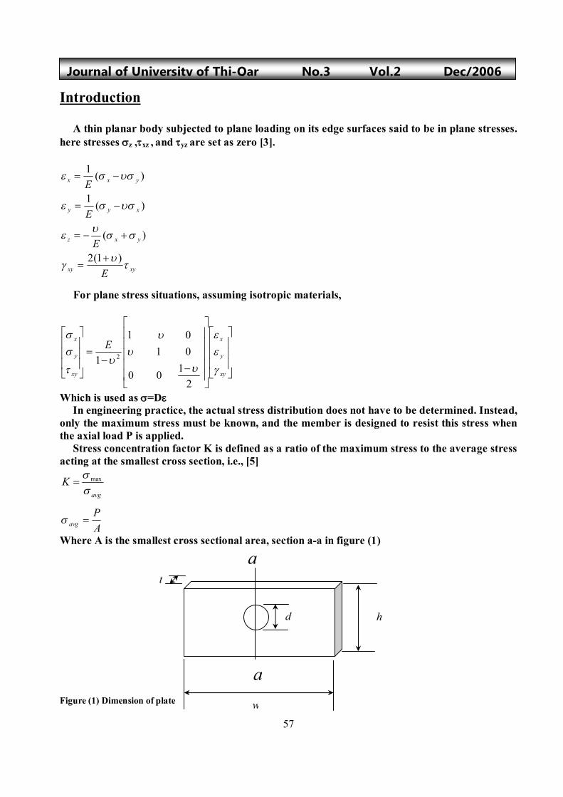
Where is the direct tension stress effect on the plate Problem Modeling and Boundary conditions A plate with such a loading as shown in figure (2) can exist any where in space. The dimension and properties of the plate are listed below: w=300 mm h=200 mm t=10 mm E=200 GPa (Steel alloys Structural A36) =0.32 (Steel alloys Structural A36) =3 MPa (Arbitrary) The symmetry of the geometry and symmetry of the loading can be used effectively. Let x and y represent the axis of symmetry as shown in figure (2). The nodal displacement components are those in the x and y directions, denoted by ux and uy respectively. Both variables are independent on the z direction. The suggests that the part which is one quarter of the full area, with the loading and boundary conditions as shown below is all that is needed to solve the problem. Figure (2) Axis of Symmetry for Plate with Hole
x
y
dww
tdwwt
tdwP
avg
*)(**
*)(
x
y
59
Journal of University of Thi-Qar No.3 Vol.2 Dec/2006
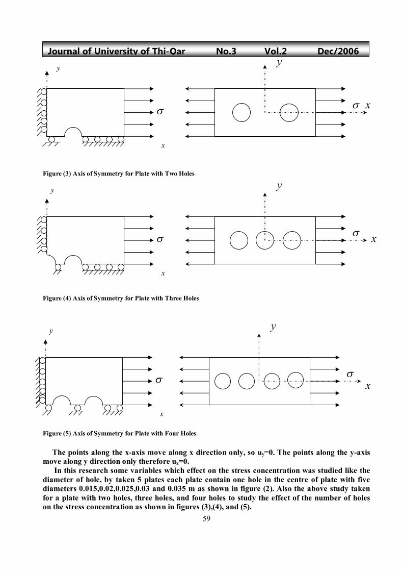
Figure (3) Axis of Symmetry for Plate with Two Holes Figure (4) Axis of Symmetry for Plate with Three Holes Figure (5) Axis of Symmetry for Plate with Four Holes The points along the x-axis move along x direction only, so uy=0. The points along the y-axis move along y direction only therefore ux=0. In this research some variables which effect on the stress concentration was studied like the diameter of hole, by taken 5 plates each plate contain one hole in the centre of plate with five diameters 0.015,0.02,0.025,0.03 and 0.035 m as shown in figure (2). Also the above study taken for a plate with two holes, three holes, and four holes to study the effect of the number of holes on the stress concentration as shown in figures (3),(4), and (5).
x
yy
x
x
y
x
y
y
x
y
x
60
Journal of University of Thi-Qar No.3 Vol.2 Dec/2006
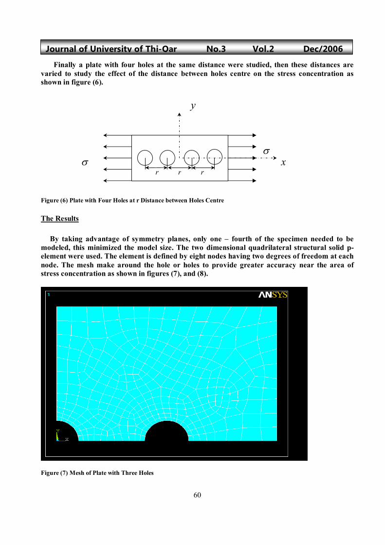
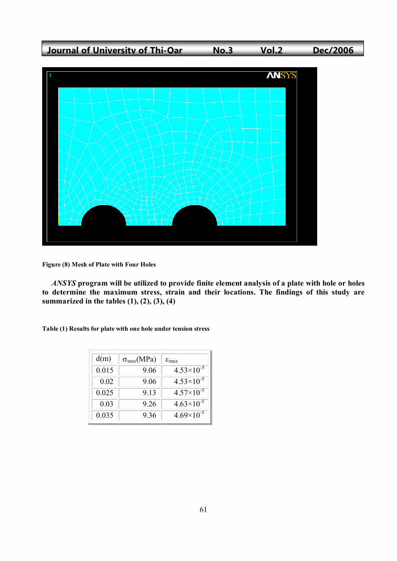
Finally a plate with four holes at the same distance were studied, then these distances are varied to study the effect of the distance between holes centre on the stress concentration as shown in figure (6). Figure (6) Plate with Four Holes at r Distance between Holes Centre The Results By taking advantage of symmetry planes, only one – fourth of the specimen needed to be modeled, this minimized the model size. The two dimensional quadrilateral structural solid p-element were used. The element is defined by eight nodes having two degrees of freedom at each node. The mesh make around the hole or holes to provide greater accuracy near the area of stress concentration as shown in figures (7), and (8). Figure (7) Mesh of Plate with Three Holes
y
xr r r
61
Journal of University of Thi-Qar No.3 Vol.2 Dec/2006
Figure (8) Mesh of Plate with Four Holes ANSYS program will be utilized to provide finite element analysis of a plate with hole or holes to determine the maximum stress, strain and their locations. The findings of this study are summarized in the tables (1), (2), (3), (4) Table (1) Results for plate with one hole under tension stress
d(m) max(MPa) max
0.015 9.06 4.53×10⁻⁵
0.02 9.06 4.53×10⁻⁵ 0.025 9.13 4.57×10⁻⁵ 0.03 9.26 4.63×10⁻⁵
0.035 9.36 4.69×10⁻⁵
62
Journal of University of Thi-Qar No.3 Vol.2 Dec/2006 Table (2) Results for plate with two holes under tension stress Table (3) Results for plate with three holes under tension stress Table (4) Results for plate with four holes under tension stress
d(m) max(MPa) max
0.015 8.92 4.47×10⁻⁵
0.02 8.96 4.47×10⁻⁵ 0.025 8.96 4.47×10⁻⁵ 0.03 9 4.50×10⁻⁵
0.035 9.03 4.52×10⁻⁵
d(m) max(MPa) max
0.015 8.87 4.43×10⁻⁵
0.02 8.88 4.43×10⁻⁵ 0.025 8.88 4.43×10⁻⁵ 0.03 8.89 4.44×10⁻⁵
0.035 8.96 4.48×10⁻⁵
d(m) max(MPa) max 0.015 8.85 4.42×10⁻⁵ 0.02 8.79 4.40×10⁻⁵
0.025 8.71 4.35×10⁻⁵ 0.03 8.78 4.42×10⁻⁵
0.035 8.89 4.49×10⁻⁵
63
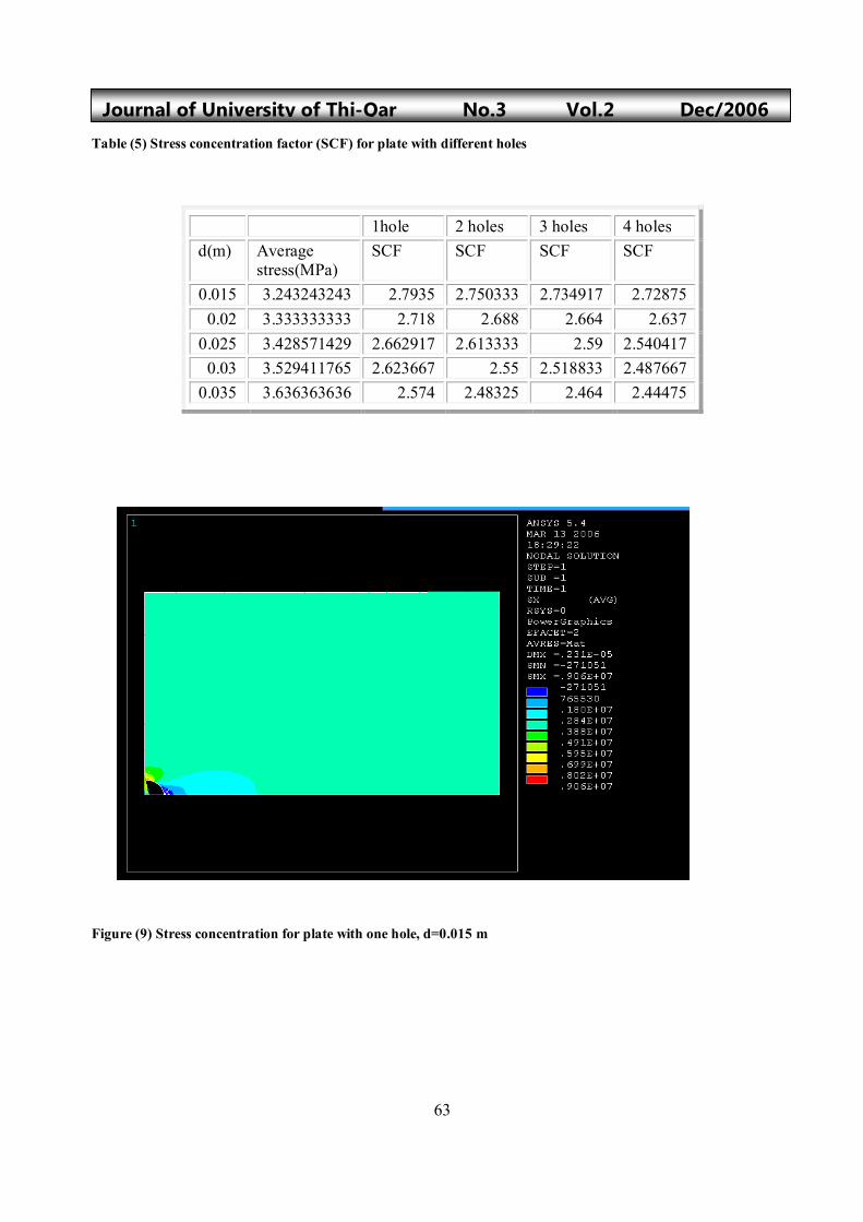
Journal of University of Thi-Qar No.3 Vol.2 Dec/2006 Table (5) Stress concentration factor (SCF) for plate with different holes Figure (9) Stress concentration for plate with one hole, d=0.015 m
1hole 2 holes 3 holes 4 holes d(m) Average
stress(MPa) SCF SCF SCF SCF
0.015 3.243243243 2.7935 2.750333 2.734917 2.72875 0.02 3.333333333 2.718 2.688 2.664 2.637
0.025 3.428571429 2.662917 2.613333 2.59 2.540417 0.03 3.529411765 2.623667 2.55 2.518833 2.487667
0.035 3.636363636 2.574 2.48325 2.464 2.44475

64
Journal of University of Thi-Qar No.3 Vol.2 Dec/2006
Figure (10) Stress concentration for plate with two holes, d=0.015 m, the distance between center of holes r=0.1 m Figure (11) Stress concentration for plate with three holes, d=0.015 m, the distance between center of holes r=0.075 m
65
Journal of University of Thi-Qar No.3 Vol.2 Dec/2006
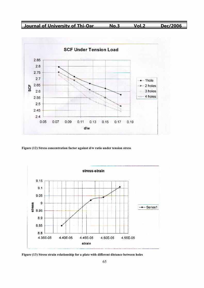
Figure (12) Stress concentration factor against d/w ratio under tension stress Figure (13) Stress strain relationship for a plate with different distance between holes
66
Journal of University of Thi-Qar No.3 Vol.2 Dec/2006
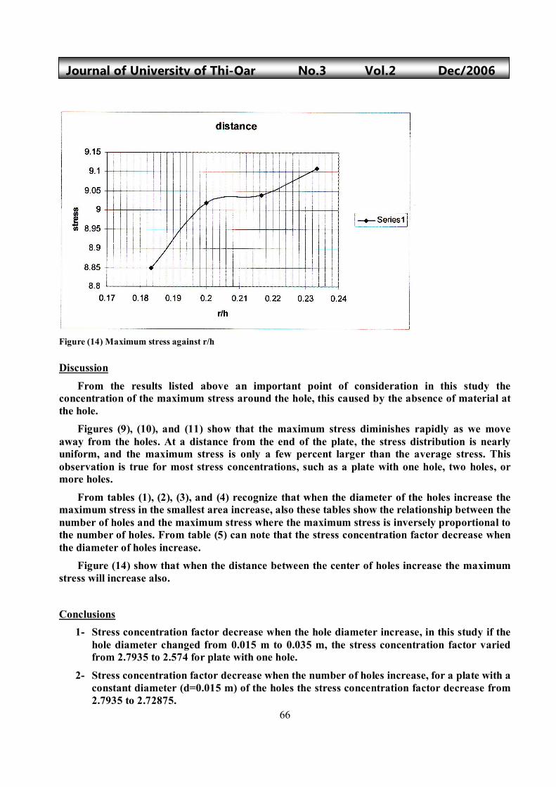
Figure (14) Maximum stress against r/h Discussion
From the results listed above an important point of consideration in this study the concentration of the maximum stress around the hole, this caused by the absence of material at the hole. Figures (9), (10), and (11) show that the maximum stress diminishes rapidly as we move away from the holes. At a distance from the end of the plate, the stress distribution is nearly uniform, and the maximum stress is only a few percent larger than the average stress. This observation is true for most stress concentrations, such as a plate with one hole, two holes, or more holes.
From tables (1), (2), (3), and (4) recognize that when the diameter of the holes increase the maximum stress in the smallest area increase, also these tables show the relationship between the number of holes and the maximum stress where the maximum stress is inversely proportional to the number of holes. From table (5) can note that the stress concentration factor decrease when the diameter of holes increase. Figure (14) show that when the distance between the center of holes increase the maximum stress will increase also.
Conclusions 1- Stress concentration factor decrease when the hole diameter increase, in this study if the
hole diameter changed from 0.015 m to 0.035 m, the stress concentration factor varied from 2.7935 to 2.574 for plate with one hole.
2- Stress concentration factor decrease when the number of holes increase, for a plate with a constant diameter (d=0.015 m) of the holes the stress concentration factor decrease from 2.7935 to 2.72875.
67
Journal of University of Thi-Qar No.3 Vol.2 Dec/2006
References [1] W.D.Webster, Jr. , “An Isoparametric Finite Element with Nodal
Derivatives”, Transaction of the ASME, Vol.48, 1981.
[2] R.Ahmed,”Analysis of Stress Concentration at Holes in Components
Made of 2195 Aluminum-Lithium”, NASA Technical Paper 3554, May 19٩5.
[3] E. Hinton, D.R.J.Owen,”Finite Element Programming”, Academic
Press, 1 977.
[4] R.C.Hibbeler,”Mechanics of Materials”, Prentice Hall, 2000.
[5] James M.Gere,” Mechanics of Materials”, Brooks/Cole,2001
[6] ANSYS Theory Manual, Rev. 5.4
[7] ANSYS Structural Analysis Guide, Rev. 5.4


![INSTALLATION GUIDE SHARK Aluminum Skid Plate Set...SKID PLATES INSTALLATION 1. Rear Skid Plate [1] installation. Place rear skid plate on appropriate holes and screw bolts (12) and](https://img.pdfslide.net/doc/110x75/6149e85912c9616cbc69116f/installation-guide-shark-aluminum-skid-plate-set-skid-plates-installation-1.jpg)