Embed Size (px)
Citation preview
i Wherever you see this symbol, it is important to access the on-line course as there is interactive material that cannot be fully shown in this reference manual.
Theory and Instrumentation of GC
Gas Supply and Pressure Control

Aims and Objectives Aims
To outline the nature and quality of the gases required for GC analysis
To describe and highlight the various methods for controlling gas pressure and cleanliness –including troubleshooting strategies
To outline the use of gas generators as a viable alternative to cylinders for GC gas supply
To describe the principles of manual and electronic pressure control for GC carrier, inlet and detector gas regulation
To explain the differences between constant pressure and constant flow experiments in GC
Objectives
At the end of this Section you should be able to:
Recognise the gases required for carrier, inlet and detector operation
Describe the required gas cleanliness and propose practical solutions for ensuring gas cleanliness requirements are met
Describe which gases may be supplied by generator
Illustrate various means be which gas flows are controlled and regulated
Identify the two primary types of gas flow control and demonstrate that you understand the differences between them using schematic diagrams
Explain how GC analyses might differ when separations are carried out in constant flow or constant pressure mode
© Crawford Scientific www.chromacademy.com
2
Content Gases Required for GC 3 Gas Supply Management 5 Regulators 6 Tubing 7 Quality of Gas Supply 8 Hydrocarbon traps 9 Moisture Traps 10 Oxygen Traps 11 Gas Generators Using Hydrogen in the Lab 11 Hydrogen Safety 13 Manual Pressure Control 14 Electronic Pressure Control 15 Pressure / Flow Programming 16
© Crawford Scientific www.chromacademy.com
3
Gases Required for GC Modern Gas Chromatographs may require several different gases in order to operate. The nature and purity of the gas required is dictated by the type of inlet, column and detector system used. The number and type of gases is mainly dictated by the detector system used.
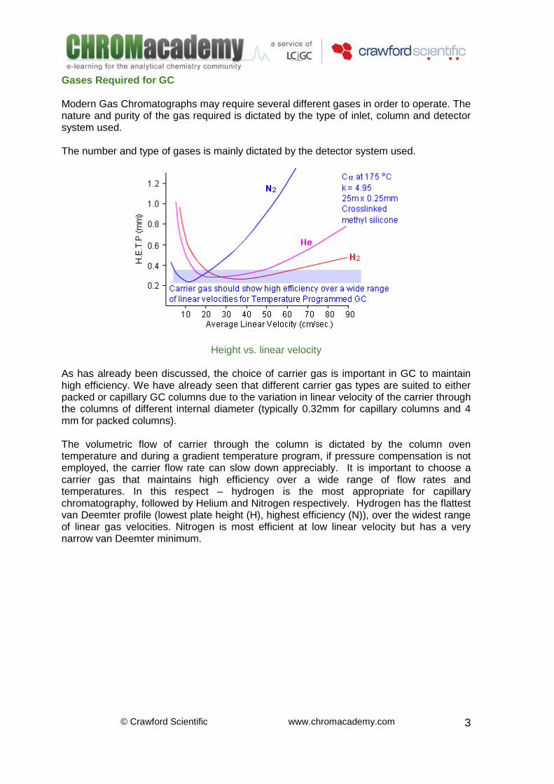
Height vs. linear velocity As has already been discussed, the choice of carrier gas is important in GC to maintain high efficiency. We have already seen that different carrier gas types are suited to either packed or capillary GC columns due to the variation in linear velocity of the carrier through the columns of different internal diameter (typically 0.32mm for capillary columns and 4 mm for packed columns). The volumetric flow of carrier through the column is dictated by the column oven temperature and during a gradient temperature program, if pressure compensation is not employed, the carrier flow rate can slow down appreciably. It is important to choose a carrier gas that maintains high efficiency over a wide range of flow rates and temperatures. In this respect – hydrogen is the most appropriate for capillary chromatography, followed by Helium and Nitrogen respectively. Hydrogen has the flattest van Deemter profile (lowest plate height (H), highest efficiency (N)), over the widest range of linear gas velocities. Nitrogen is most efficient at low linear velocity but has a very narrow van Deemter minimum.
© Crawford Scientific www.chromacademy.com
4
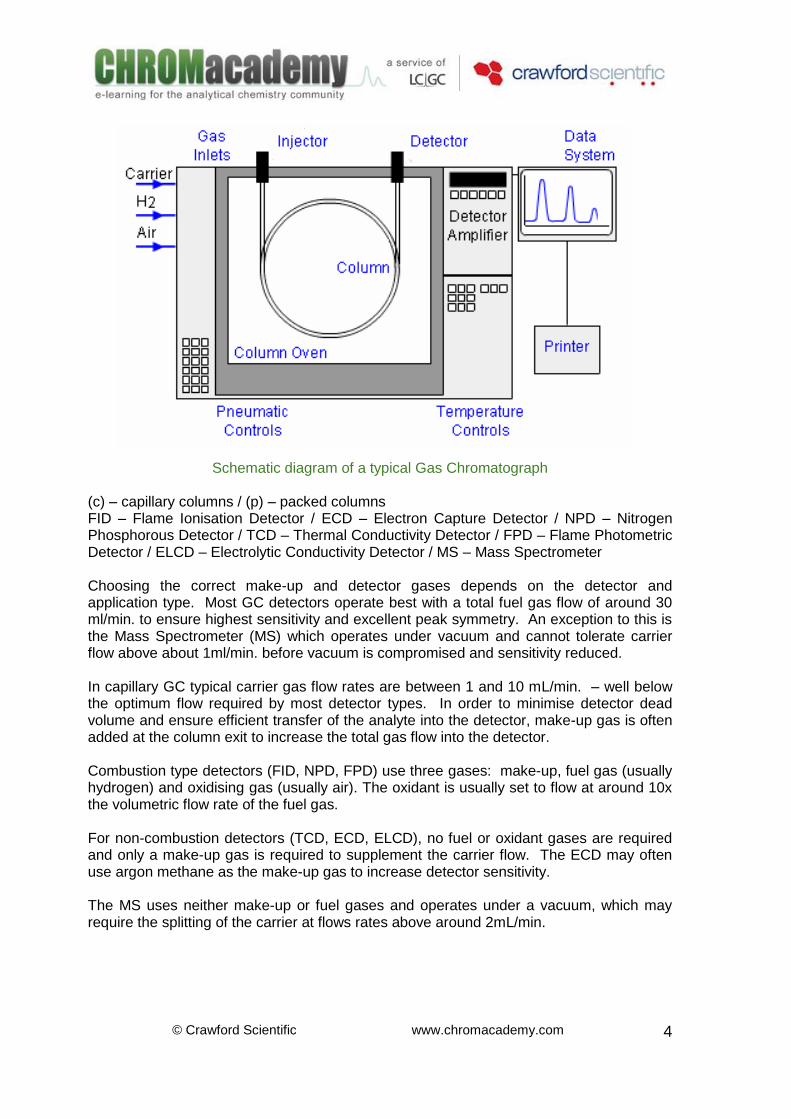
Schematic diagram of a typical Gas Chromatograph (c) – capillary columns / (p) – packed columns FID – Flame Ionisation Detector / ECD – Electron Capture Detector / NPD – Nitrogen Phosphorous Detector / TCD – Thermal Conductivity Detector / FPD – Flame Photometric Detector / ELCD – Electrolytic Conductivity Detector / MS – Mass Spectrometer Choosing the correct make-up and detector gases depends on the detector and application type. Most GC detectors operate best with a total fuel gas flow of around 30 ml/min. to ensure highest sensitivity and excellent peak symmetry. An exception to this is the Mass Spectrometer (MS) which operates under vacuum and cannot tolerate carrier flow above about 1ml/min. before vacuum is compromised and sensitivity reduced. In capillary GC typical carrier gas flow rates are between 1 and 10 mL/min. – well below the optimum flow required by most detector types. In order to minimise detector dead volume and ensure efficient transfer of the analyte into the detector, make-up gas is often added at the column exit to increase the total gas flow into the detector. Combustion type detectors (FID, NPD, FPD) use three gases: make-up, fuel gas (usually hydrogen) and oxidising gas (usually air). The oxidant is usually set to flow at around 10x the volumetric flow rate of the fuel gas. For non-combustion detectors (TCD, ECD, ELCD), no fuel or oxidant gases are required and only a make-up gas is required to supplement the carrier flow. The ECD may often use argon methane as the make-up gas to increase detector sensitivity. The MS uses neither make-up or fuel gases and operates under a vacuum, which may require the splitting of the carrier at flows rates above around 2mL/min.
© Crawford Scientific www.chromacademy.com
5
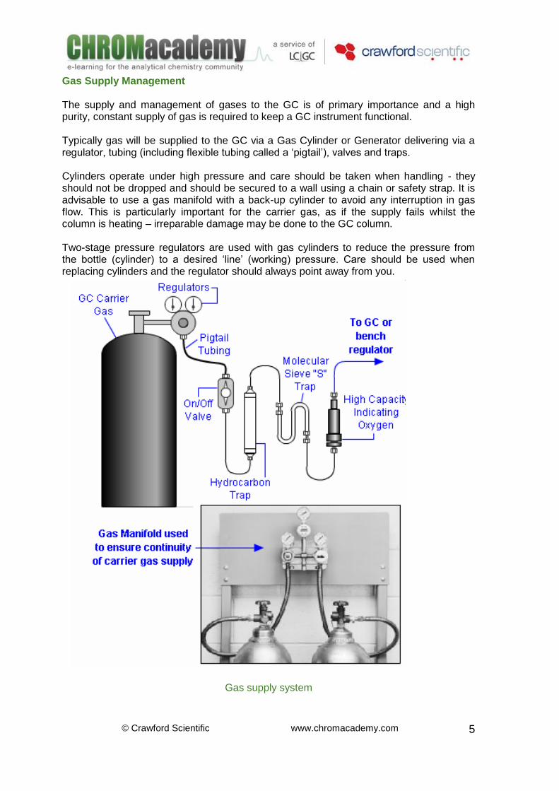
Gas Supply Management The supply and management of gases to the GC is of primary importance and a high purity, constant supply of gas is required to keep a GC instrument functional. Typically gas will be supplied to the GC via a Gas Cylinder or Generator delivering via a regulator, tubing (including flexible tubing called a ‘pigtail’), valves and traps. Cylinders operate under high pressure and care should be taken when handling - they should not be dropped and should be secured to a wall using a chain or safety strap. It is advisable to use a gas manifold with a back-up cylinder to avoid any interruption in gas flow. This is particularly important for the carrier gas, as if the supply fails whilst the column is heating – irreparable damage may be done to the GC column. Two-stage pressure regulators are used with gas cylinders to reduce the pressure from the bottle (cylinder) to a desired ‘line’ (working) pressure. Care should be used when replacing cylinders and the regulator should always point away from you.
Gas supply system
© Crawford Scientific www.chromacademy.com
6
After installing a fresh gas cylinder, the cylinder valve should always be fully opened –to prevent the cylinder from shutting down unpredictably (usually within the first 24 hours), due to internal pressure reduction within the regulator. As a general rule a cylinder should be replaced when the main bottle pressure reaches 200-300 psi (or 10% of the original cylinder pressure). As the cylinder pressure drops, impurities such as moisture, hydrocarbons and small particulates concentrate within the gas –drastically reducing the gas purity. Regulators The purpose of a pressure regulator is to maintain constant gas pressure to the GC. Two types are available – cylinder regulators and line regulators. Cylinder regulators attcahye directly to the cylinder valve and regulate the pressure from the cylinder (2500psi) down to a more useable line pressure (around 100psi). Cylinder regulators have two pressure gauges – an inlet (high pressure) gauge which reads the cylinder pressure, and a delivery (outlet) gauge. The final delivery pressure is adjustable by turning the knob on the front of the regulator.
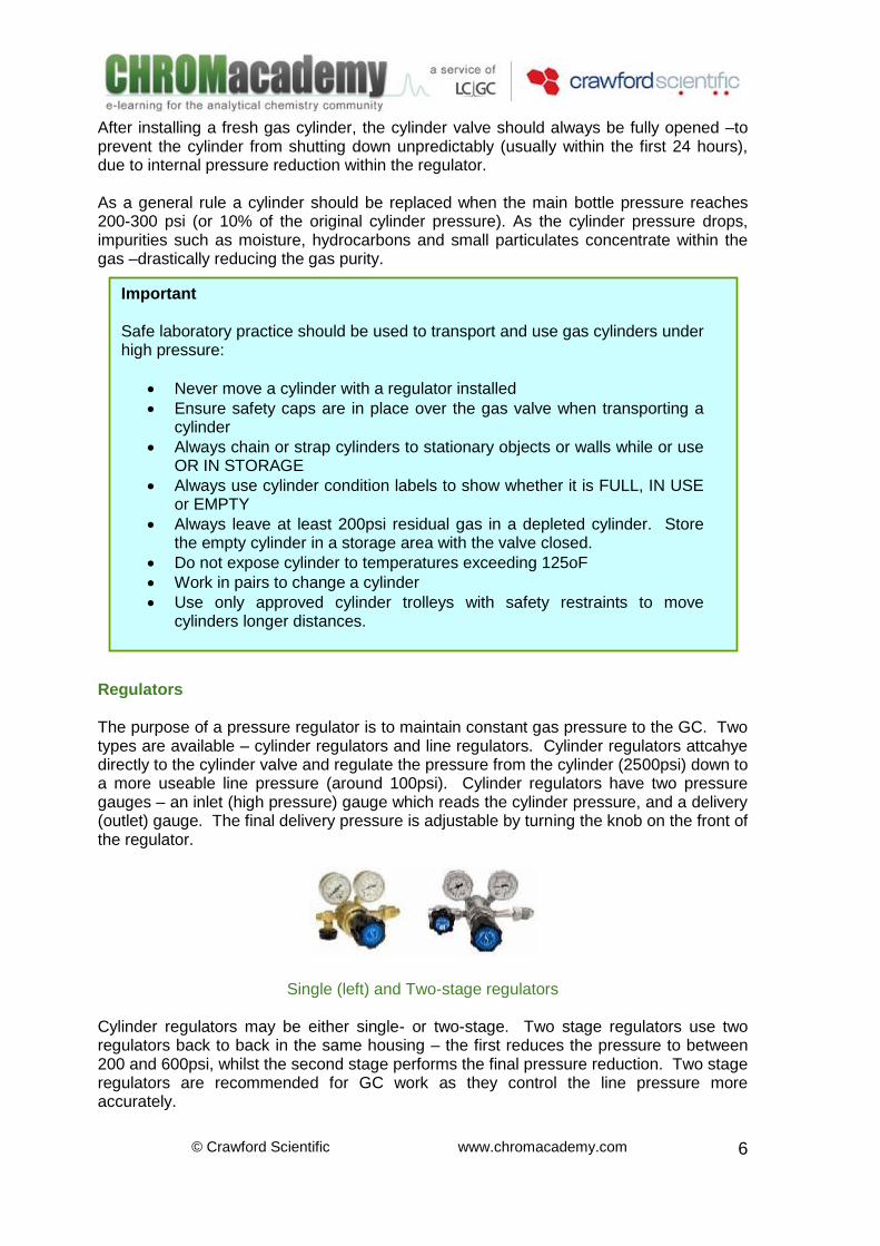
Single (left) and Two-stage regulators Cylinder regulators may be either single- or two-stage. Two stage regulators use two regulators back to back in the same housing – the first reduces the pressure to between 200 and 600psi, whilst the second stage performs the final pressure reduction. Two stage regulators are recommended for GC work as they control the line pressure more accurately.
Important Safe laboratory practice should be used to transport and use gas cylinders under high pressure:
Never move a cylinder with a regulator installed
Ensure safety caps are in place over the gas valve when transporting a cylinder
Always chain or strap cylinders to stationary objects or walls while or use OR IN STORAGE
Always use cylinder condition labels to show whether it is FULL, IN USE or EMPTY
Always leave at least 200psi residual gas in a depleted cylinder. Store the empty cylinder in a storage area with the valve closed.
Do not expose cylinder to temperatures exceeding 125oF
Work in pairs to change a cylinder
Use only approved cylinder trolleys with safety restraints to move cylinders longer distances.
© Crawford Scientific www.chromacademy.com
7
Line regulators have a lower allowable inlet pressure (around 300psi) and should never be directly attached to the cylinder. Line regulators are used to further reduce the line pressure to that required at point of use (the GC gas inlet manifold or pressure controller). Line regulators are always single stage and are often equipped with a single pressure gauge.
Oxygen, moisture and elastomeric components can migrate through rubber diaphragms and enter the carrier gas - therefore all regulators should have Teflon coated stainless steel diaphragms to minimise carrier contamination. Air, Hydrogen have different regulator types from Nitrogen, Helium and Argon. You should check to ensure you have the correct regulator type prior to fitting. Tubing
Pigtails are commonly installed between the regulator and the gas line. They allow the necessary flexibility when replacing the cylinder and are typically constructed of braided stainless steel with a Teflon core. It is possibl;e for moisture and oxygen to permeate through the Teflon and so purifiers should always be used down line –as close to the GC as possible.
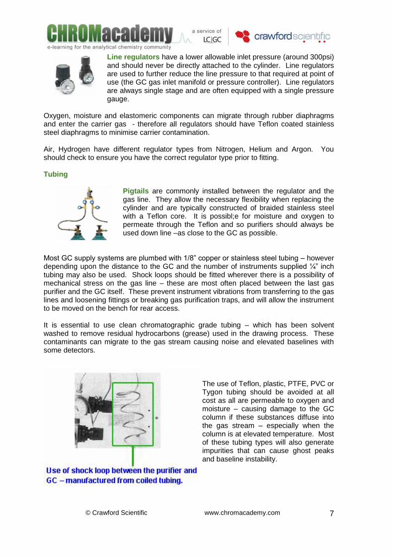
Most GC supply systems are plumbed with 1/8” copper or stainless steel tubing – however depending upon the distance to the GC and the number of instruments supplied ¼” inch tubing may also be used. Shock loops should be fitted wherever there is a possibility of mechanical stress on the gas line – these are most often placed between the last gas purifier and the GC itself. These prevent instrument vibrations from transferring to the gas lines and loosening fittings or breaking gas purification traps, and will allow the instrument to be moved on the bench for rear access. It is essential to use clean chromatographic grade tubing – which has been solvent washed to remove residual hydrocarbons (grease) used in the drawing process. These contaminants can migrate to the gas stream causing noise and elevated baselines with some detectors.
The use of Teflon, plastic, PTFE, PVC or Tygon tubing should be avoided at all cost as all are permeable to oxygen and moisture – causing damage to the GC column if these substances diffuse into the gas stream – especially when the column is at elevated temperature. Most of these tubing types will also generate impurities that can cause ghost peaks and baseline instability.
© Crawford Scientific www.chromacademy.com
8
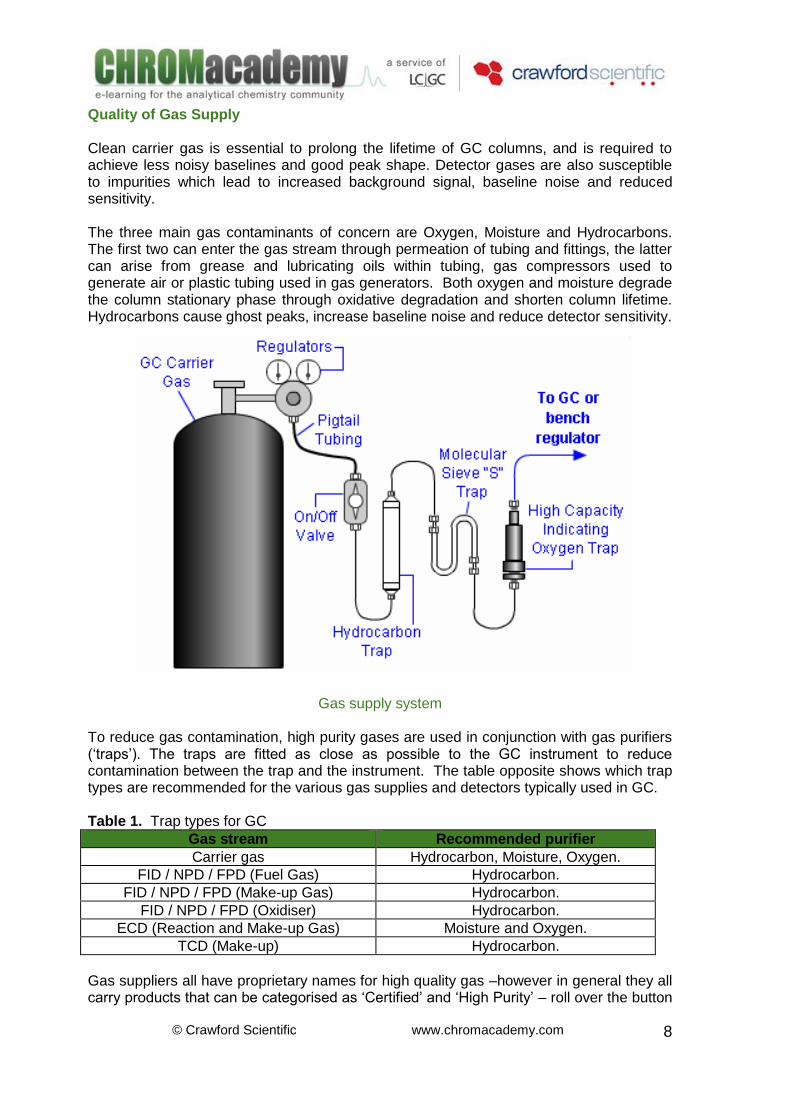
Quality of Gas Supply Clean carrier gas is essential to prolong the lifetime of GC columns, and is required to achieve less noisy baselines and good peak shape. Detector gases are also susceptible to impurities which lead to increased background signal, baseline noise and reduced sensitivity. The three main gas contaminants of concern are Oxygen, Moisture and Hydrocarbons. The first two can enter the gas stream through permeation of tubing and fittings, the latter can arise from grease and lubricating oils within tubing, gas compressors used to generate air or plastic tubing used in gas generators. Both oxygen and moisture degrade the column stationary phase through oxidative degradation and shorten column lifetime. Hydrocarbons cause ghost peaks, increase baseline noise and reduce detector sensitivity.
Gas supply system To reduce gas contamination, high purity gases are used in conjunction with gas purifiers (‘traps’). The traps are fitted as close as possible to the GC instrument to reduce contamination between the trap and the instrument. The table opposite shows which trap types are recommended for the various gas supplies and detectors typically used in GC. Table 1. Trap types for GC
Gas stream Recommended purifier
Carrier gas Hydrocarbon, Moisture, Oxygen.
FID / NPD / FPD (Fuel Gas) Hydrocarbon.
FID / NPD / FPD (Make-up Gas) Hydrocarbon.
FID / NPD / FPD (Oxidiser) Hydrocarbon.
ECD (Reaction and Make-up Gas) Moisture and Oxygen.
TCD (Make-up) Hydrocarbon.
Gas suppliers all have proprietary names for high quality gas –however in general they all carry products that can be categorised as ‘Certified’ and ‘High Purity’ – roll over the button
© Crawford Scientific www.chromacademy.com
9
opposite to view the typical purity of these gases. Wherever possible the gas supplied to the GC should contain less than 1ppm of the relevant impurity. Table 2. Trap types for GC
Impurity (ppm) Certified Gas Levels (99.9995%)
High Purity Gas Levels (99.995%)
Oxygen 1 3
Moisture 0.5 1.5
Hydrocarbons 0.5 1
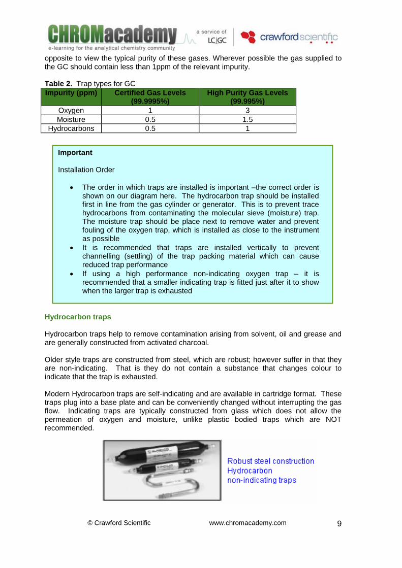
Hydrocarbon traps Hydrocarbon traps help to remove contamination arising from solvent, oil and grease and are generally constructed from activated charcoal. Older style traps are constructed from steel, which are robust; however suffer in that they are non-indicating. That is they do not contain a substance that changes colour to indicate that the trap is exhausted. Modern Hydrocarbon traps are self-indicating and are available in cartridge format. These traps plug into a base plate and can be conveniently changed without interrupting the gas flow. Indicating traps are typically constructed from glass which does not allow the permeation of oxygen and moisture, unlike plastic bodied traps which are NOT recommended.
Important Installation Order
The order in which traps are installed is important –the correct order is shown on our diagram here. The hydrocarbon trap should be installed first in line from the gas cylinder or generator. This is to prevent trace hydrocarbons from contaminating the molecular sieve (moisture) trap. The moisture trap should be place next to remove water and prevent fouling of the oxygen trap, which is installed as close to the instrument as possible
It is recommended that traps are installed vertically to prevent channelling (settling) of the trap packing material which can cause reduced trap performance
If using a high performance non-indicating oxygen trap – it is recommended that a smaller indicating trap is fitted just after it to show when the larger trap is exhausted
© Crawford Scientific www.chromacademy.com
10
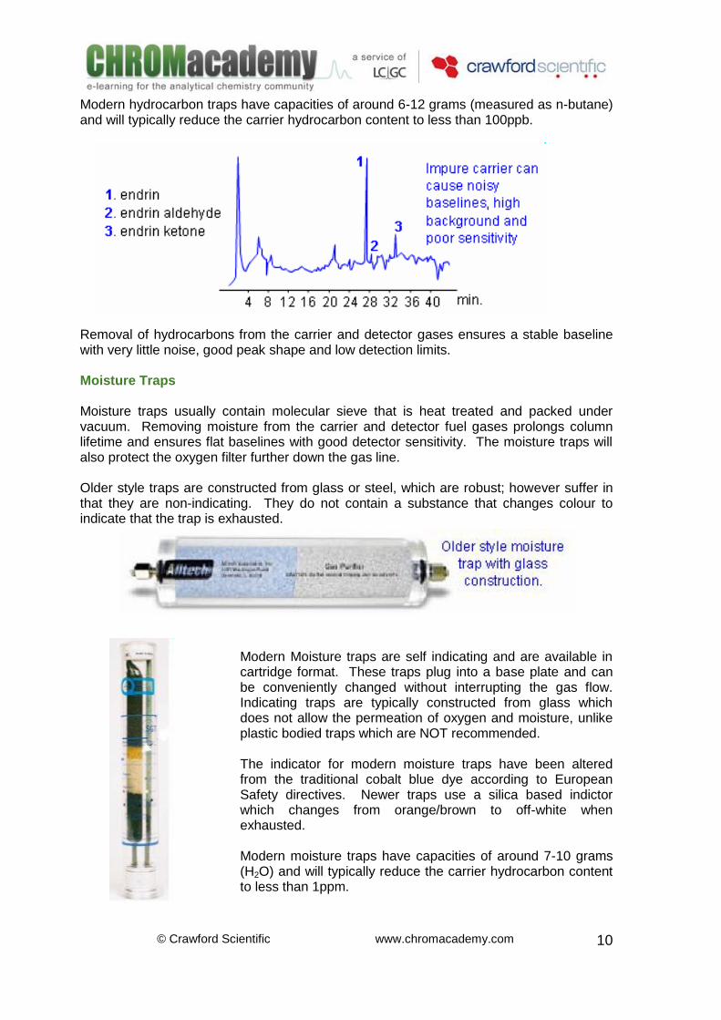
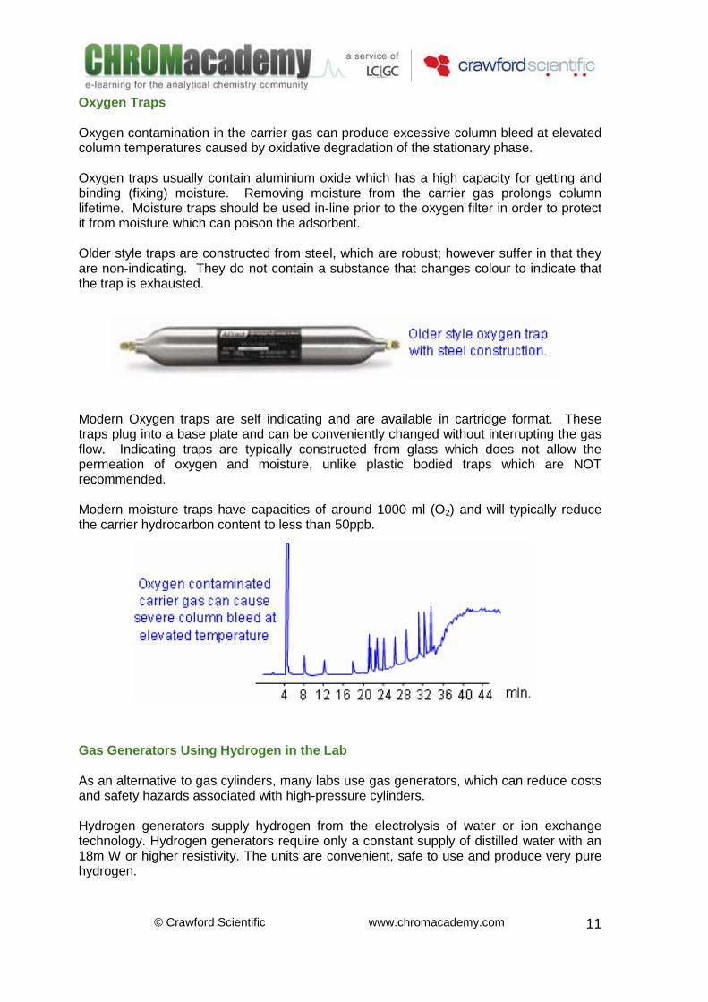
Modern hydrocarbon traps have capacities of around 6-12 grams (measured as n-butane) and will typically reduce the carrier hydrocarbon content to less than 100ppb. Removal of hydrocarbons from the carrier and detector gases ensures a stable baseline with very little noise, good peak shape and low detection limits. Moisture Traps Moisture traps usually contain molecular sieve that is heat treated and packed under vacuum. Removing moisture from the carrier and detector fuel gases prolongs column lifetime and ensures flat baselines with good detector sensitivity. The moisture traps will also protect the oxygen filter further down the gas line. Older style traps are constructed from glass or steel, which are robust; however suffer in that they are non-indicating. They do not contain a substance that changes colour to indicate that the trap is exhausted.
Modern Moisture traps are self indicating and are available in cartridge format. These traps plug into a base plate and can be conveniently changed without interrupting the gas flow. Indicating traps are typically constructed from glass which does not allow the permeation of oxygen and moisture, unlike plastic bodied traps which are NOT recommended.
The indicator for modern moisture traps have been altered from the traditional cobalt blue dye according to European Safety directives. Newer traps use a silica based indictor which changes from orange/brown to off-white when exhausted.
Modern moisture traps have capacities of around 7-10 grams (H2O) and will typically reduce the carrier hydrocarbon content to less than 1ppm.
© Crawford Scientific www.chromacademy.com
11
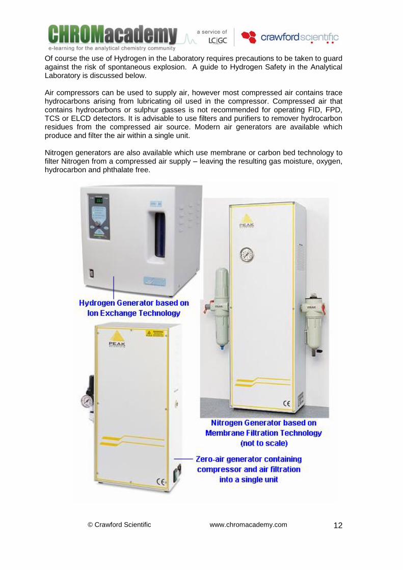
Oxygen Traps Oxygen contamination in the carrier gas can produce excessive column bleed at elevated column temperatures caused by oxidative degradation of the stationary phase. Oxygen traps usually contain aluminium oxide which has a high capacity for getting and binding (fixing) moisture. Removing moisture from the carrier gas prolongs column lifetime. Moisture traps should be used in-line prior to the oxygen filter in order to protect it from moisture which can poison the adsorbent. Older style traps are constructed from steel, which are robust; however suffer in that they are non-indicating. They do not contain a substance that changes colour to indicate that the trap is exhausted. Modern Oxygen traps are self indicating and are available in cartridge format. These traps plug into a base plate and can be conveniently changed without interrupting the gas flow. Indicating traps are typically constructed from glass which does not allow the permeation of oxygen and moisture, unlike plastic bodied traps which are NOT recommended. Modern moisture traps have capacities of around 1000 ml (O2) and will typically reduce the carrier hydrocarbon content to less than 50ppb. Gas Generators Using Hydrogen in the Lab As an alternative to gas cylinders, many labs use gas generators, which can reduce costs and safety hazards associated with high-pressure cylinders. Hydrogen generators supply hydrogen from the electrolysis of water or ion exchange technology. Hydrogen generators require only a constant supply of distilled water with an 18m W or higher resistivity. The units are convenient, safe to use and produce very pure hydrogen.
© Crawford Scientific www.chromacademy.com
12
Of course the use of Hydrogen in the Laboratory requires precautions to be taken to guard against the risk of spontaneous explosion. A guide to Hydrogen Safety in the Analytical Laboratory is discussed below. Air compressors can be used to supply air, however most compressed air contains trace hydrocarbons arising from lubricating oil used in the compressor. Compressed air that contains hydrocarbons or sulphur gasses is not recommended for operating FID, FPD, TCS or ELCD detectors. It is advisable to use filters and purifiers to remover hydrocarbon residues from the compressed air source. Modern air generators are available which produce and filter the air within a single unit. Nitrogen generators are also available which use membrane or carbon bed technology to filter Nitrogen from a compressed air supply – leaving the resulting gas moisture, oxygen, hydrocarbon and phthalate free.
© Crawford Scientific www.chromacademy.com
13
Hydrogen Safety Hydrogen is spontaneously explosive when its concentration in air exceeds 4% (at 6300C or above!!). Proper safety precautions should therefore be used in order to prevent explosion within the column oven. The concentration of hydrogen is very unlikely to exceed 4% even in the smallest of laboratories due to the large volume of air against the rate at which hydrogen is produced by a typical generator. Most generator manufacturers will employ several safety features within their instrumentation including:
Low volumetric output
Low reservoir volumes (most <100mL)
Back pressure monitoring to assess leaks
Internal pressure monitoring to assess production run-away or over production of gas
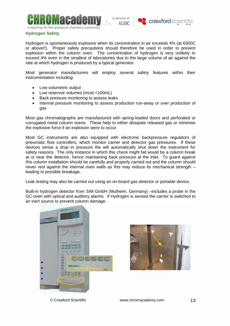
Most gas chromatographs are manufactured with spring-loaded doors and perforated or corrugated metal column ovens. These help to either dissipate released gas or minimise the explosive force if an explosion were to occur. Most GC instruments are also equipped with electronic backpressure regulators of pneumatic flow controllers, which monitor carrier and detector gas pressures. If these devices sense a drop in pressure the will automatically shut down the instrument for safety reasons. The only instance in which this check might fail would be a column break at or near the detector, hence maintaining back pressure at the inlet. To guard against this column installation should be carefully and properly carried out and the column should never rest against the internal oven walls as this may reduce its mechanical strength – leading to possible breakage. Leak testing may also be carried out using an on-board gas detector or portable device. Built-in hydrogen detector from SIM GmbH (Mulheim, Germany) –includes a probe in the GC-oven with optical and auditory alarms. If Hydrogen is sensed the carrier is switched to an inert source to prevent column damage.
© Crawford Scientific www.chromacademy.com
14
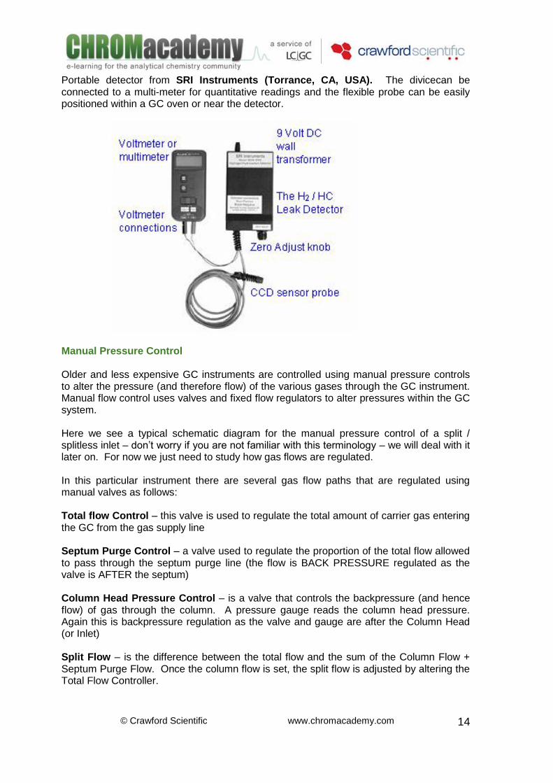
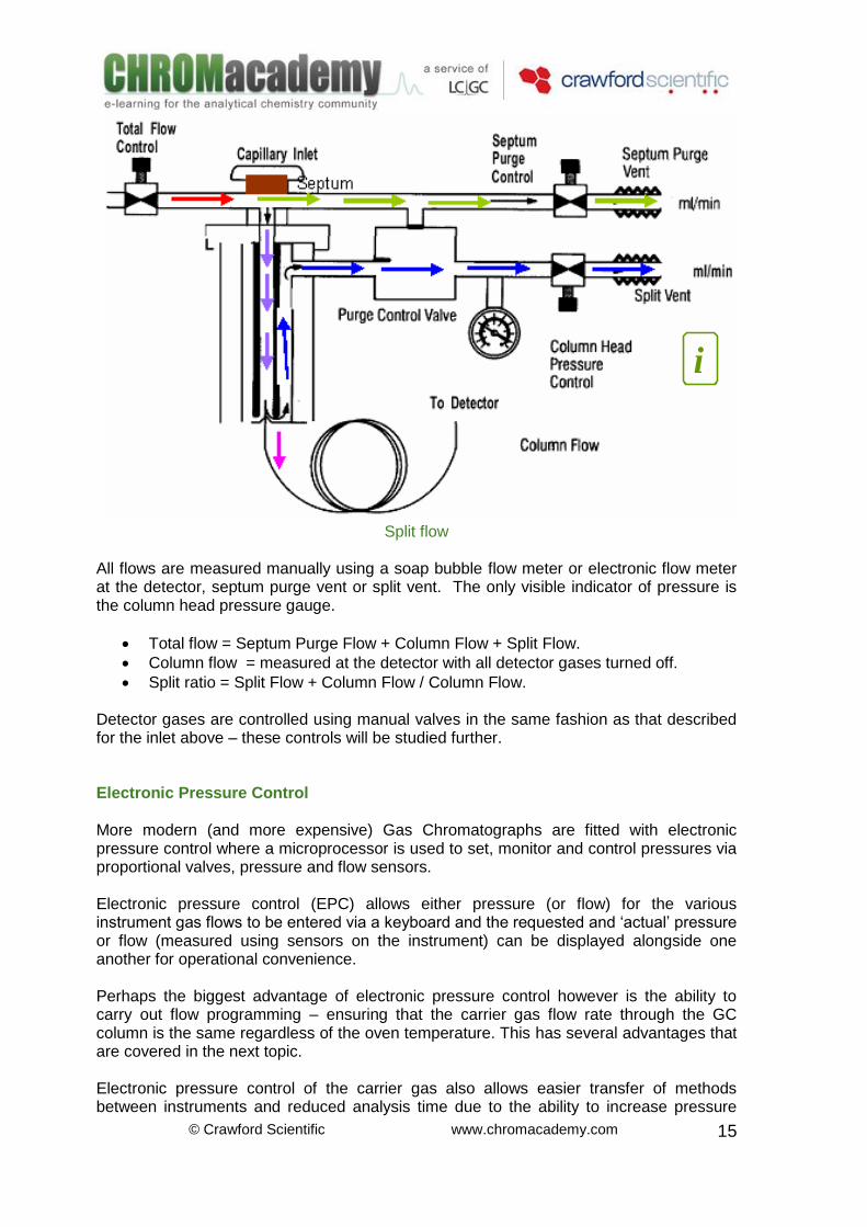
Portable detector from SRI Instruments (Torrance, CA, USA). The divicecan be connected to a multi-meter for quantitative readings and the flexible probe can be easily positioned within a GC oven or near the detector. Manual Pressure Control Older and less expensive GC instruments are controlled using manual pressure controls to alter the pressure (and therefore flow) of the various gases through the GC instrument. Manual flow control uses valves and fixed flow regulators to alter pressures within the GC system. Here we see a typical schematic diagram for the manual pressure control of a split / splitless inlet – don’t worry if you are not familiar with this terminology – we will deal with it later on. For now we just need to study how gas flows are regulated. In this particular instrument there are several gas flow paths that are regulated using manual valves as follows: Total flow Control – this valve is used to regulate the total amount of carrier gas entering the GC from the gas supply line Septum Purge Control – a valve used to regulate the proportion of the total flow allowed to pass through the septum purge line (the flow is BACK PRESSURE regulated as the valve is AFTER the septum) Column Head Pressure Control – is a valve that controls the backpressure (and hence flow) of gas through the column. A pressure gauge reads the column head pressure. Again this is backpressure regulation as the valve and gauge are after the Column Head (or Inlet) Split Flow – is the difference between the total flow and the sum of the Column Flow + Septum Purge Flow. Once the column flow is set, the split flow is adjusted by altering the Total Flow Controller.
© Crawford Scientific www.chromacademy.com
15
Split flow All flows are measured manually using a soap bubble flow meter or electronic flow meter at the detector, septum purge vent or split vent. The only visible indicator of pressure is the column head pressure gauge.
Total flow = Septum Purge Flow + Column Flow + Split Flow.
Column flow = measured at the detector with all detector gases turned off.
Split ratio = Split Flow + Column Flow / Column Flow. Detector gases are controlled using manual valves in the same fashion as that described for the inlet above – these controls will be studied further. Electronic Pressure Control More modern (and more expensive) Gas Chromatographs are fitted with electronic pressure control where a microprocessor is used to set, monitor and control pressures via proportional valves, pressure and flow sensors. Electronic pressure control (EPC) allows either pressure (or flow) for the various instrument gas flows to be entered via a keyboard and the requested and ‘actual’ pressure or flow (measured using sensors on the instrument) can be displayed alongside one another for operational convenience. Perhaps the biggest advantage of electronic pressure control however is the ability to carry out flow programming – ensuring that the carrier gas flow rate through the GC column is the same regardless of the oven temperature. This has several advantages that are covered in the next topic. Electronic pressure control of the carrier gas also allows easier transfer of methods between instruments and reduced analysis time due to the ability to increase pressure
i
© Crawford Scientific www.chromacademy.com
16
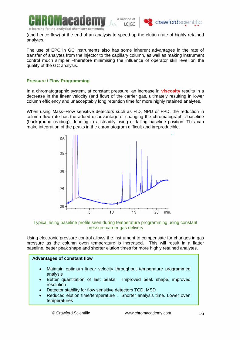
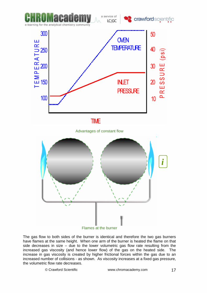
(and hence flow) at the end of an analysis to speed up the elution rate of highly retained analytes. The use of EPC in GC instruments also has some inherent advantages in the rate of transfer of analytes from the injector to the capillary column, as well as making instrument control much simpler –therefore minimising the influence of operator skill level on the quality of the GC analysis. Pressure / Flow Programming In a chromatographic system, at constant pressure, an increase in viscosity results in a decrease in the linear velocity (and flow) of the carrier gas, ultimately resulting in lower column efficiency and unacceptably long retention time for more highly retained analytes. When using Mass–Flow sensitive detectors such as FID, NPD or FPD, the reduction in column flow rate has the added disadvantage of changing the chromatographic baseline (background reading) –leading to a steadily rising or falling baseline position. This can make integration of the peaks in the chromatogram difficult and irreproducible.
Typical rising baseline profile seen during temperature programming using constant pressure carrier gas delivery
Using electronic pressure control allows the instrument to compensate for changes in gas pressure as the column oven temperature is increased. This will result in a flatter baseline, better peak shape and shorter elution times for more highly retained analytes.
Advantages of constant flow
Maintain optimum linear velocity throughout temperature programmed analysis
Better quantitation of last peaks. Improved peak shape, improved resolution
Detector stability for flow sensitive detectors TCD, MSD
Reduced elution time/temperature . Shorter analysis time. Lower oven temperatures
© Crawford Scientific www.chromacademy.com
17
Advantages of constant flow
Flames at the burner The gas flow to both sides of the burner is identical and therefore the two gas burners have flames at the same height. When one arm of the burner is heated the flame on that side decreases in size – due to the lower volumetric gas flow rate resulting from the increased gas viscosity (and hence lower flow) of the gas on the heated side. The increase in gas viscosity is created by higher frictional forces within the gas due to an increased number of collisions - as shown. As viscosity increases at a fixed gas pressure, the volumetric flow rate decreases.
i
© Crawford Scientific www.chromacademy.com
18
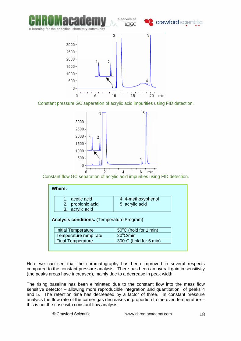
Constant pressure GC separation of acrylic acid impurities using FID detection.
Constant flow GC separation of acrylic acid impurities using FID detection.
Here we can see that the chromatography has been improved in several respects compared to the constant pressure analysis. There has been an overall gain in sensitivity (the peaks areas have increased), mainly due to a decrease in peak width. The rising baseline has been eliminated due to the constant flow into the mass flow sensitive detector – allowing more reproducible integration and quantitation of peaks 4 and 5. The retention time has decreased by a factor of three. In constant pressure analysis the flow rate of the carrier gas decreases in proportion to the oven temperature –this is not the case with constant flow analysis.
Where:
1. acetic acid 2. propionic acid 3. acrylic acid
4. 4-methoxyphenol 5. acrylic acid
Analysis conditions. (Temperature Program)
Initial Temperature 50oC (hold for 1 min)
Temperature ramp rate 20oC/min
Final Temperature 300oC (hold for 5 min)
© Crawford Scientific www.chromacademy.com
19
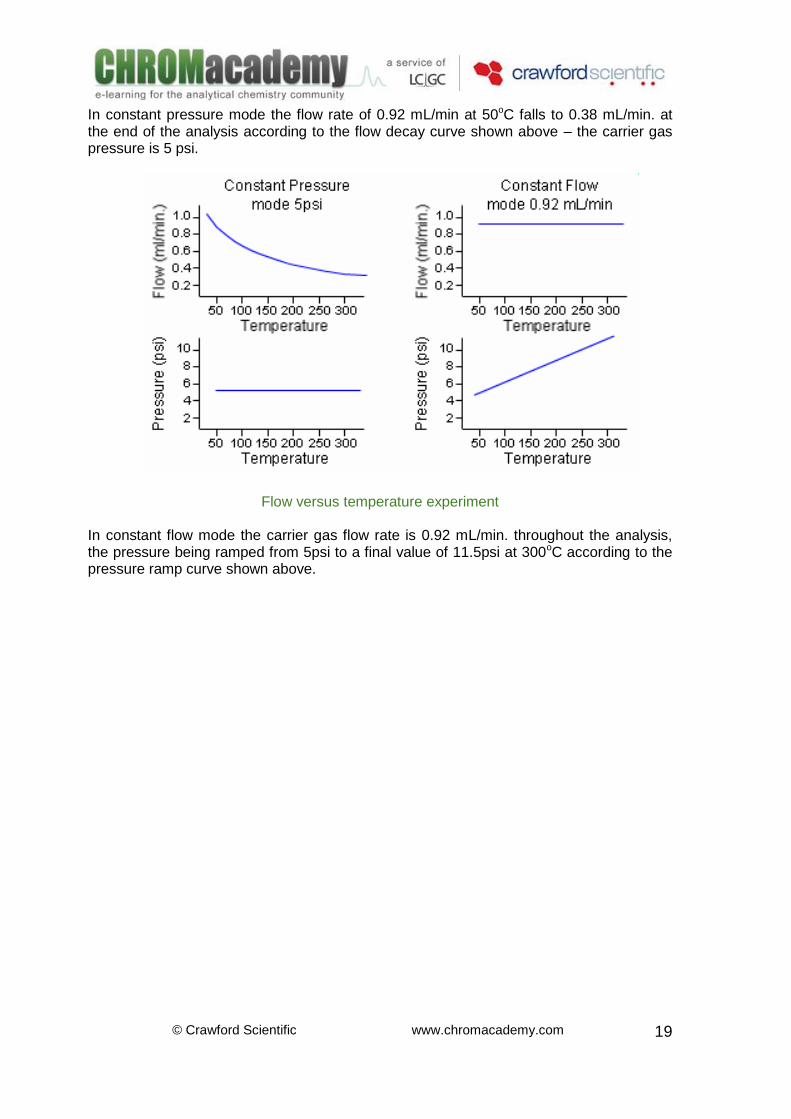
In constant pressure mode the flow rate of 0.92 mL/min at 50oC falls to 0.38 mL/min. at the end of the analysis according to the flow decay curve shown above – the carrier gas pressure is 5 psi.
Flow versus temperature experiment In constant flow mode the carrier gas flow rate is 0.92 mL/min. throughout the analysis, the pressure being ramped from 5psi to a final value of 11.5psi at 300oC according to the pressure ramp curve shown above.


![[PPT]Liquid Chromatography Fundamentals - Theory · Web viewLiquid Chromatography Fundamentals - Theory Keywords HPLC, LC, HPLC theory, HPLC fundamentals, teaching HPLC, learning](https://img.pdfslide.net/doc/110x75/5b1aa2c67f8b9a3c258de481/pptliquid-chromatography-fundamentals-theory-web-viewliquid-chromatography.jpg)


![What is HPLC? High Performance Liquid Chromatography High Pressure Liquid Chromatography (usually true] Hewlett Packard Liquid Chromatography (a joke)](https://img.pdfslide.net/doc/110x75/56649c855503460f9493c784/what-is-hplc-high-performance-liquid-chromatography-high-pressure-liquid-chromatography.jpg)

![Sensitive Determination of Anticancer Drug Methotrexate ... · chromatography (IC) [19], high performance liquid chromatography (HPLC) [20,21], ... they usually require cumbersome](https://img.pdfslide.net/doc/110x75/5f61c7747a80615db8104052/sensitive-determination-of-anticancer-drug-methotrexate-chromatography-ic.jpg)