Embed Size (px)
Citation preview
viii
“ There are only three possible sources of energy which can be used to generate electricity in space – chemical, nuclear, or solar. Each energy source, . . . has its own intrinsic characteristics, and their differences determine which source is uniquely the best for a specific mission.”
Systems for Nuclear Auxiliary Power…A Report by the Commission – 1964
1Photo Credit
The Early Years Space Nuclear Power Systems Take Flight1O
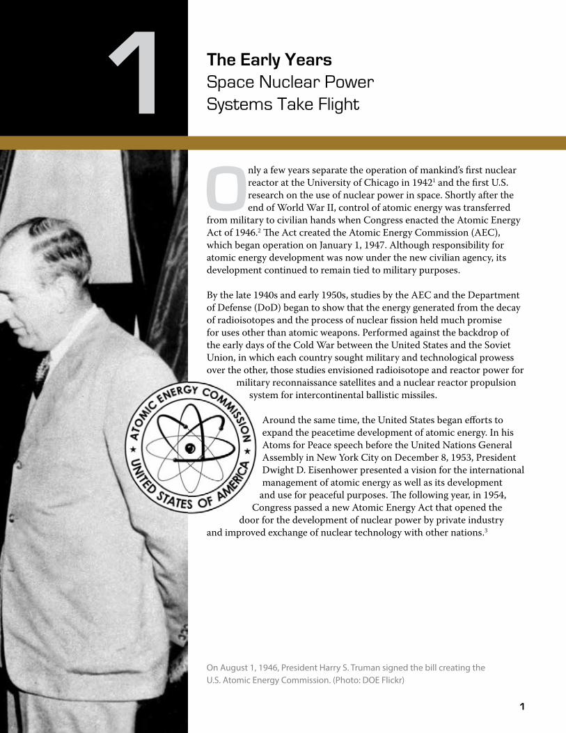
nly a few years separate the operation of mankind’s first nuclear reactor at the University of Chicago in 19421 and the first U.S. research on the use of nuclear power in space. Shortly after the end of World War II, control of atomic energy was transferred
from military to civilian hands when Congress enacted the Atomic Energy Act of 1946.2 �e Act created the Atomic Energy Commission (AEC), which began operation on January 1, 1947. Although responsibility for atomic energy development was now under the new civilian agency, its development continued to remain tied to military purposes.
By the late 1940s and early 1950s, studies by the AEC and the Department of Defense (DoD) began to show that the energy generated from the decay of radioisotopes and the process of nuclear fission held much promise for uses other than atomic weapons. Performed against the backdrop of the early days of the Cold War between the United States and the Soviet Union, in which each country sought military and technological prowess over the other, those studies envisioned radioisotope and reactor power for
military reconnaissance satellites and a nuclear reactor propulsion system for intercontinental ballistic missiles.
Around the same time, the United States began efforts to expand the peacetime development of atomic energy. In his Atoms for Peace speech before the United Nations General Assembly in New York City on December 8, 1953, President Dwight D. Eisenhower presented a vision for the international management of atomic energy as well as its development
and use for peaceful purposes. �e following year, in 1954, Congress passed a new Atomic Energy Act that opened the
door for the development of nuclear power by private industry and improved exchange of nuclear technology with other nations.3
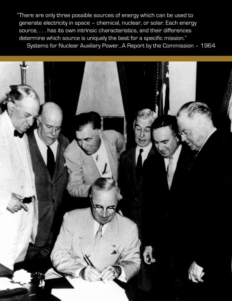
On August 1, 1946, President Harry S. Truman signed the bill creating the U.S. Atomic Energy Commission. (Photo: DOE Flickr)
2
The Early Years Space Nuclear Power Systems Take FlightThe Early Years Space Nuclear Power Systems Take Flight
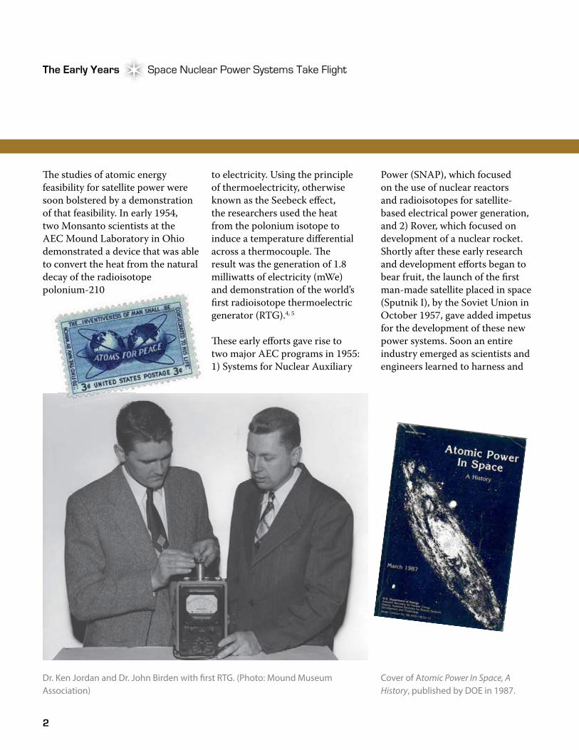
�e studies of atomic energy feasibility for satellite power were soon bolstered by a demonstration of that feasibility. In early 1954, two Monsanto scientists at the AEC Mound Laboratory in Ohio demonstrated a device that was able to convert the heat from the natural decay of the radioisotope polonium-210
to electricity. Using the principle of thermoelectricity, otherwise known as the Seebeck effect, the researchers used the heat from the polonium isotope to induce a temperature differential across a thermocouple. �e result was the generation of 1.8 milliwatts of electricity (mWe) and demonstration of the world’s first radioisotope thermoelectric generator (RTG).4, 5
�ese early efforts gave rise to two major AEC programs in 1955: 1) Systems for Nuclear Auxiliary
Power (SNAP), which focused on the use of nuclear reactors and radioisotopes for satellite-based electrical power generation, and 2) Rover, which focused on development of a nuclear rocket. Shortly after these early research and development efforts began to bear fruit, the launch of the first man-made satellite placed in space (Sputnik I), by the Soviet Union in October 1957, gave added impetus for the development of these new power systems. Soon an entire industry emerged as scientists and engineers learned to harness and
Dr. Ken Jordan and Dr. John Birden with �rst RTG. (Photo: Mound Museum Association)
Cover of Atomic Power In Space, A History, published by DOE in 1987.
3
Atomic Power in Space II Chapter 1Atomic Power in Space II Chapter 1
use the energy of the atom in ever newer and more creative ways, eventually leading to the far reaches of space.
�e space nuclear power system technologies and programs undertaken in the United States since the mid-1950s include radioisotope power systems (RPSs) (both static and dynamic) as well as reactor systems developed for space power and propulsion. An earlier history (pre-1987) of space nuclear power development and use, which focused largely on RTG technology, is presented in Atomic Power in Space.3 �e history and technologies captured in that and other works describe the pioneering efforts that solved many of the technical problems of using nuclear power in space and demonstrated that nuclear power is well-suited for certain types of space missions. �ese early efforts are briefly reviewed in this chapter because they set the stage for the programs and missions discussed in the remainder of this book. �ey also provide a basis for understanding the evolution of space nuclear power system technologies and some of the political and social environments that influenced their development.
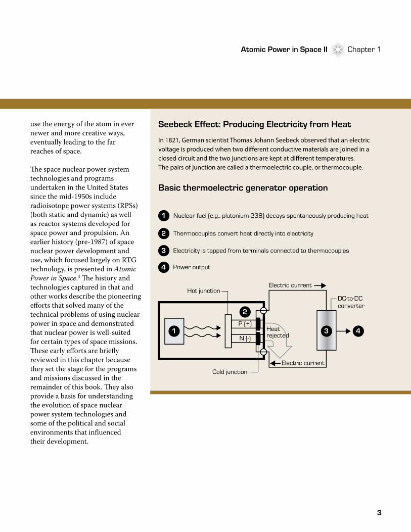
Seebeck Effect: Producing Electricity from Heat
In 1821, German scientist Thomas Johann Seebeck observed that an electric voltage is produced when two di�erent conductive materials are joined in a closed circuit and the two junctions are kept at di�erent temperatures. The pairs of junction are called a thermoelectric couple, or thermocouple.
Basic thermoelectric generator operation
Hot junction
Cold junction
Nuclear fuel (e.g., plutonium-238) decays spontaneously producing heat
P (+)
Electric current
Heatrejected
DC-to-DC converter
Power output
Electric current
N (-)
1
Thermocouples convert heat directly into electricity2
Electricity is tapped from terminals connected to thermocouples 3
4
2
3 41
4
The Early Years Space Nuclear Power Systems Take FlightThe Early Years Space Nuclear Power Systems Take Flight
SNAP Takes Hold
�e SNAP program consisted of two separate but parallel efforts. Development of systems for the conversion of heat generated from the natural decay of radioisotopes was awarded to the Martin Nuclear Division of the Martin Company out of Baltimore, Maryland. Development of systems to employ the heat generated from the fission process within nuclear reactors was awarded to the Atomics International Division of North American Aviation, Inc. To differentiate the radioisotope systems from the reactor systems, AEC devised a simple numbering scheme—odd numbers (i.e., SNAP-1) were used to
designate RPSs while even numbers (i.e., SNAP-2) were assigned to reactor systems. Letters of the alphabet were used to indicate design differences among the same system. Although systems were developed for space and terrestrial uses, this book focuses only on space nuclear power systems.
�e first RPS developed by the Martin Company, SNAP-1, used the heat from the decay of cerium-144 to boil liquid mercury to drive a small turbine, with the goal of generating 500 watts of electric power (We) for a 60-day lifetime. Although testing demonstrated the feasibility of the first dynamic RPS that used a Rankine
thermodynamic cycle, the unit was never fully developed for space use due to factors that included the need for a system with a longer operating life and the advent of thermoelectric materials with high efficiency.3
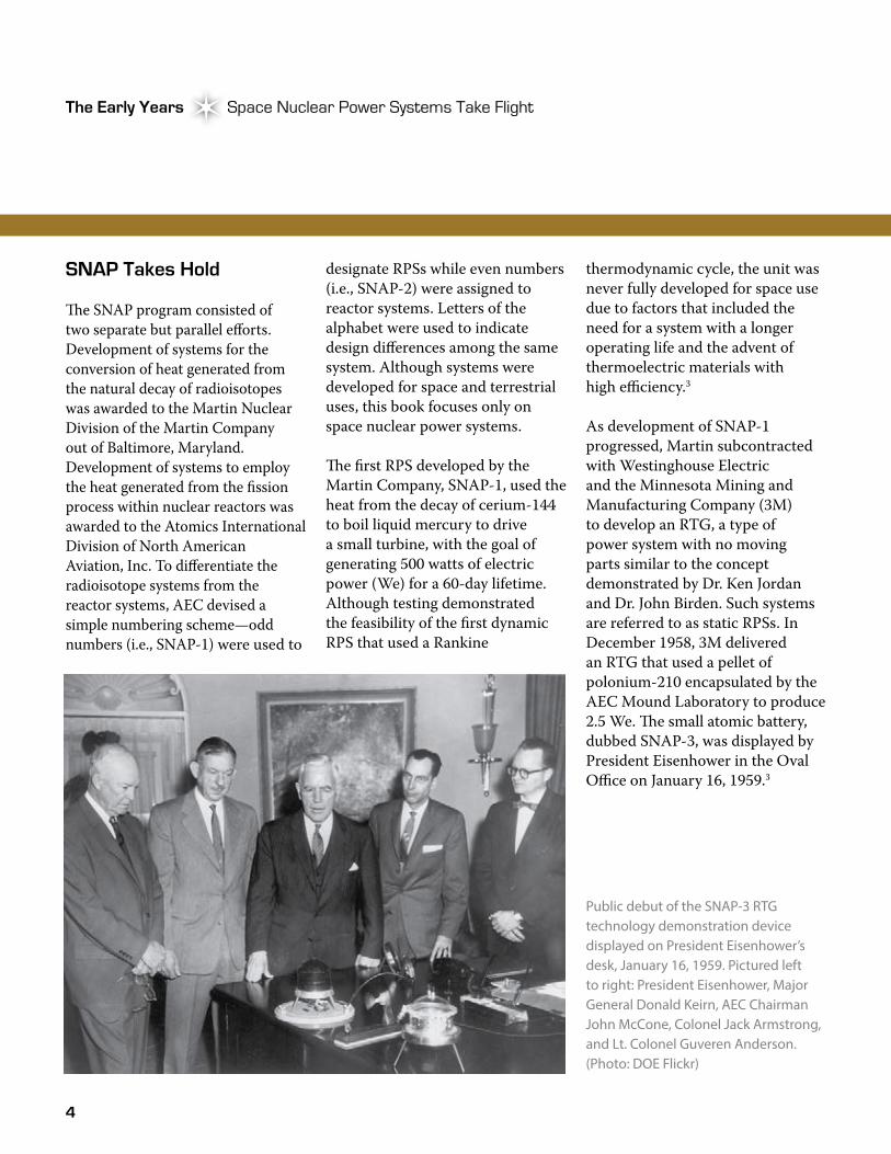
As development of SNAP-1 progressed, Martin subcontracted with Westinghouse Electric and the Minnesota Mining and Manufacturing Company (3M) to develop an RTG, a type of power system with no moving parts similar to the concept demonstrated by Dr. Ken Jordan and Dr. John Birden. Such systems are referred to as static RPSs. In December 1958, 3M delivered an RTG that used a pellet of polonium-210 encapsulated by the AEC Mound Laboratory to produce 2.5 We. �e small atomic battery, dubbed SNAP-3, was displayed by President Eisenhower in the Oval Office on January 16, 1959.3
Public debut of the SNAP-3 RTG technology demonstration device displayed on President Eisenhower’s desk, January 16, 1959. Pictured left to right: President Eisenhower, Major General Donald Keirn, AEC Chairman John McCone, Colonel Jack Armstrong, and Lt. Colonel Guveren Anderson. (Photo: DOE Flickr)
5
Atomic Power in Space II Chapter 1Atomic Power in Space II Chapter 1
While the SNAP-3B unit provided supplementary power for the Transit-4 satellites, the next goal was to demonstrate the feasibility of using an RTG as the sole source of power for a Navy satellite. Driven by the desire for a power source with improved survivability, the SNAP-9A RTG was created, which was used on the Navy navigational satellites Transit-5BN-1, 5BN-2, and 5BN-3. Like SNAP-3B, the SNAP-9A unit was
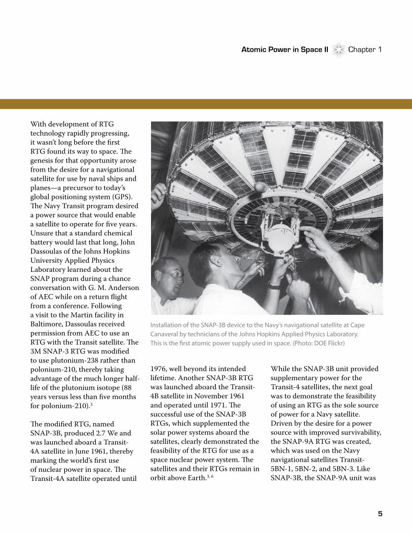
With development of RTG technology rapidly progressing, it wasn’t long before the first RTG found its way to space. �e genesis for that opportunity arose from the desire for a navigational satellite for use by naval ships and planes—a precursor to today’s global positioning system (GPS). �e Navy Transit program desired a power source that would enable a satellite to operate for five years. Unsure that a standard chemical battery would last that long, John Dassoulas of the Johns Hopkins University Applied Physics Laboratory learned about the SNAP program during a chance conversation with G. M. Anderson of AEC while on a return flight from a conference. Following a visit to the Martin facility in Baltimore, Dassoulas received permission from AEC to use an RTG with the Transit satellite. �e 3M SNAP-3 RTG was modified to use plutonium-238 rather than polonium-210, thereby taking advantage of the much longer half-life of the plutonium isotope (88 years versus less than five months for polonium-210).3
�e modified RTG, named SNAP-3B, produced 2.7 We and was launched aboard a Transit-4A satellite in June 1961, thereby marking the world’s first use of nuclear power in space. �e Transit-4A satellite operated until
1976, well beyond its intended lifetime. Another SNAP-3B RTG was launched aboard the Transit-4B satellite in November 1961 and operated until 1971. �e successful use of the SNAP-3B RTGs, which supplemented the solar power systems aboard the satellites, clearly demonstrated the feasibility of the RTG for use as a space nuclear power system. �e satellites and their RTGs remain in orbit above Earth.3, 6
Installation of the SNAP-3B device to the Navy’s navigational satellite at Cape Canaveral by technicians of the Johns Hopkins Applied Physics Laboratory. This is the �rst atomic power supply used in space. (Photo: DOE Flickr)
6
The Early Years Space Nuclear Power Systems Take FlightThe Early Years Space Nuclear Power Systems Take Flight
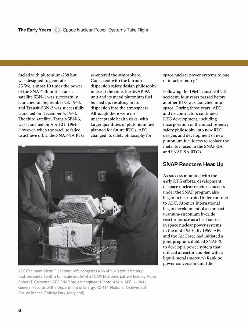
fueled with plutonium-238 but was designed to generate 25 We, almost 10 times the power of the SNAP-3B unit. Transit satellite 5BN-1 was successfully launched on September 28, 1963, and Transit-5BN-2 was successfully launched on December 5, 1963. �e third satellite, Transit-5BN-3, was launched on April 21, 1964. However, when the satellite failed to achieve orbit, the SNAP-9A RTG
re-entered the atmosphere. Consistent with the burnup-dispersion safety design philosophy in use at the time, the SNAP-9A unit and its metal plutonium fuel burned up, resulting in its dispersion into the atmosphere. Although there were no unacceptable health risks, with larger quantities of plutonium fuel planned for future RTGs, AEC changed its safety philosophy for
space nuclear power systems to one of intact re-entry.3
Following the 1964 Transit-5BN-3 accident, four years passed before another RTG was launched into space. During those years, AEC and its contractors continued RTG development, including incorporation of the intact re-entry safety philosophy into new RTG designs and development of new plutonium fuel forms to replace the metal fuel used in the SNAP-3A and SNAP-9A RTGs.
SNAP Reactors Heat Up
As success mounted with the early RTG efforts, development of space nuclear reactor concepts under the SNAP program also began to bear fruit. Under contract to AEC, Atomics International began development of a compact uranium-zirconium hydride reactor for use as a heat source in space nuclear power systems in the mid-1950s. By 1959, AEC and the Air Force had initiated a joint program, dubbed SNAP-2, to develop a power system that utilized a reactor coupled with a liquid-metal (mercury) Rankine power conversion unit (the
AEC Chairman Glenn T. Seaborg, left, compares a SNAP-9A “atomic battery” (bottom center) with a full-scale model of a SNAP-3B atomic battery held by Major Robert T. Carpenter, AEC-SNAP project engineer. (Photo: 434-N-AEC-63-7042. General Records of the Department of Energy, RG 434, National Archives Still Picture Branch, College Park, Maryland)
7
Atomic Power in Space II Chapter 1Atomic Power in Space II Chapter 1
conversion technology used in the SNAP-1 program). Development of the mercury Rankine cycle conversion system was led by the �ompson-Ramo-Wooldridge Company. However, due to the lack of a mission, the SNAP-2 program was redirected into a broader space nuclear power program in 1963.7
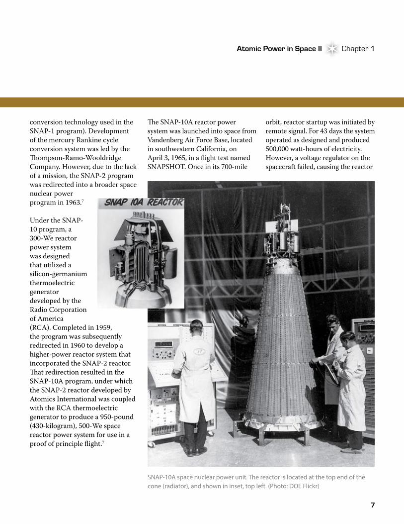
Under the SNAP-10 program, a 300-We reactor power system was designed that utilized a silicon-germanium thermoelectric generator developed by the Radio Corporation of America (RCA). Completed in 1959, the program was subsequently redirected in 1960 to develop a higher-power reactor system that incorporated the SNAP-2 reactor. �at redirection resulted in the SNAP-10A program, under which the SNAP-2 reactor developed by Atomics International was coupled with the RCA thermoelectric generator to produce a 950-pound (430-kilogram), 500-We space reactor power system for use in a proof of principle flight.7
SNAP-10A space nuclear power unit. The reactor is located at the top end of the cone (radiator), and shown in inset, top left. (Photo: DOE Flickr)
�e SNAP-10A reactor power system was launched into space from Vandenberg Air Force Base, located in southwestern California, on April 3, 1965, in a flight test named SNAPSHOT. Once in its 700-mile
orbit, reactor startup was initiated by remote signal. For 43 days the system operated as designed and produced 500,000 watt-hours of electricity. However, a voltage regulator on the spacecraft failed, causing the reactor
8
The Early Years Space Nuclear Power Systems Take FlightThe Early Years Space Nuclear Power Systems Take Flight
to shut down, putting the satellite out of commission. SNAP-10A remains a significant milestone for the U.S. space program. Not only did it demonstrate the feasibility of operating a liquid-metal-cooled reactor power system safely and reliably in space, with remote startup and control, it was also the world’s first reactor power system to be successfully launched and operated in space.7
Although SNAP-10A remains the most notable achievement in the SNAP reactor program, other notable SNAP reactor programs include SNAP-8 and SNAP-50. �e SNAP-8 program was initiated in 1959, at the request of the National Aeronautics and Space Agency (NASA), to develop a reactor for use in a nuclear electric propulsion system. �e resultant reactor power system employed a mercury Rankine cycle to generate 30 to 60 kilowatts of electric power (kWe). Under the SNAP-50 program, development efforts focused on demonstration of a lithium-cooled reactor coupled with a potassium Rankine cycle capable of generating 300 to 1,000 kWe for use in electric propulsion, as well as power supplies for space vehicles and large manned satellites.7
Further research into reactor-based space power systems continued through the 1960s, but was largely discontinued in 1973 due to changing national priorities. As discussed in later chapters, interest in space nuclear reactor systems would be renewed under programs such as the Space Power Advanced Reactor (SPAR) project and the SP-100 program.8 On the RTG front, however, no such slow down occurred, as the young RTG technology was soon put to use by an even younger national space agency.
RTGs Bring Power to NASA Missions
NASA’s interest in space nuclear power systems grew against the backdrop of the Navy Transit program and the ongoing space power system development efforts of the SNAP program. NASA’s first use of the new space nuclear technology was in Earth orbit aboard a Nimbus weather satellite. A desire to supplement a 200-watt solar power system with approximately 50 We of RTG power led to development of the SNAP-19B RTG.
With a power output of approximately 23.5 We, the SNAP-19B RTG used a new heat source that reflected the intact re-entry safety design philosophy adopted by AEC following the Transit-5BN-3 accident in 1964. As such, the SNAP-19B heat source was designed to contain its plutonium fuel (microspheres) under normal operating conditions and during abnormal conditions such as a launch abort or re-entry. �e first use of the new RTG occurred in 1968 when NASA launched a Nimbus B weather satellite carrying two SNAP-19B RTGs from Vandenberg Air Force Base.
Approximately two minutes after lift-off, the rocket, carrying the satellite and its SNAP-19B RTGs, veered off course, prompting a mission-abort command. �e abort-induced explosion destroyed the launch vehicle, after which the two RTGs fell into the Santa Barbara Channel just north of San Miguel Island off the coast of California. Five months later, the SNAP-19B units were recovered – intact – from the ocean floor at a depth of approximately 300 feet (90 meters). �e SNAP-19B heat sources had performed as designed and were returned to Mound Laboratory, where the fuel was recovered and reused in a later flight.
SNAP-10A remains a significant milestone for the U.S. space program.
9
Atomic Power in Space II Chapter 1Atomic Power in Space II Chapter 1
In April 1969, NASA successfully launched a Nimbus-3 weather satellite, again carrying two SNAP-19B RTGs. �e Nimbus-3 weather satellite marked the first successful use of an RTG by NASA, thus beginning a partnership with nuclear technology that soon found itself on the moon.9
As part of the Apollo scientific missions in the 1970s, several science stations (i.e., Apollo Lunar Surface Experiments Packages) were placed on the moon. Beginning with the second lunar
landing, a new RTG (SNAP-27) was used to power the experiments packages. Built by General Electric (GE) under an AEC contract, the SNAP-27 design employed the lead-telluride thermoelectric conversion technology used by the Martin Company in previous SNAP RTGs but in a system that was designed to have the heat source inserted on the moon. Similar to other Martin RTGs, the thermoelectrics were produced by 3M. Designed for a power output of approximately 63.5 We, a total of five SNAP-27 RTGs were
eventually used in that capacity. All of the systems worked exceedingly well and provided power to more than 50 scientific experiments, as well as to the communications equipment that relayed data back to Earth, until the Apollo Lunar Surface Experiments Packages were shutdown in 1977.4
Although never deployed on the moon, another SNAP-27 RTG was launched aboard the ill-fated Apollo 13 mission in 1970. Following an explosion on the main craft, the lunar module (with the SNAP-27 RTG onboard) was jettisoned from the command module upon return to Earth. During re-entry, the lunar module disintegrated and the RTG fell into the Pacific Ocean in the vicinity of the Tonga Trench. Subsequent monitoring found no detectable radioactivity, indicating that the RTG had survived re-entry intact.
Although used during the Apollo missions, the SNAP-27 RTGs were not the first use of nuclear energy on the moon. On the first Apollo mission, the Early Apollo Scientific Experiment Package deployed by Neil Armstrong and Edwin “Buzz” Aldrin included two radioisotope heater units (RHUs), each providing 15 watts of thermal power to keep the experiment warm during the long (14 Earth-days) and cold lunar
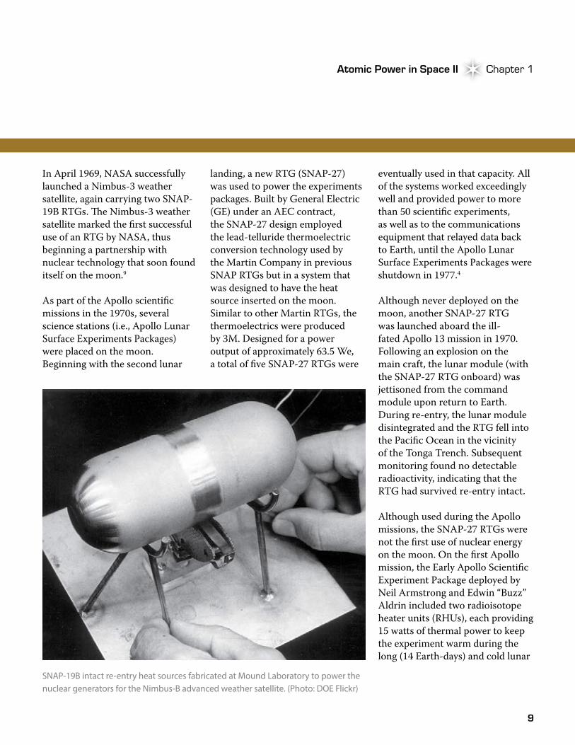
SNAP-19B intact re-entry heat sources fabricated at Mound Laboratory to power the nuclear generators for the Nimbus-B advanced weather satellite. (Photo: DOE Flickr)
10
The Early Years Space Nuclear Power Systems Take FlightThe Early Years Space Nuclear Power Systems Take Flight
nights. �e experiment package used solar cells for electrical power, which meant that the experiments shut down during the lunar night.10
During this same period, NASA also found nuclear power sources to be useful in space exploration beyond the moon. Pioneer 10 was launched in March 1972, and Pioneer 11 in April 1973, to travel beyond the asteroid belt, fly past Jupiter, and leave the solar system. Each spacecraft carried four 40-We SNAP-19 RTGs and 12 RHUs, each
designed for a heat output of one watt, to protect instruments and thrusters from low temperatures.10
Solar panels were unworkable for these missions because the energy available from the sun at such a great distance was insufficient to power the spacecraft’s systems and experiments. �e RTGs performed perfectly, supplying power long after the original 30-month missions had been achieved.3 Radio contact with Pioneer 11, which passed by Saturn as well as Jupiter, stopped in November 1995. �e radio signal
from Pioneer 10 was finally lost in January 2003, over 30 years after it was launched. �e space probes, powered solely by the RTGs, provided invaluable information about Jupiter, Saturn, and the outer solar system. As one NASA historian wrote, “�e program, perhaps this is an understatement, was a huge success. Such success would not have resulted without the four RTGs on each spacecraft providing power.”4
After the Pioneer missions, NASA continued its use of RTGs when it sent two landers to Mars in 1975. Viking 1 and Viking 2, each powered by two SNAP-19 RTGs, were launched in August and September 1975, respectively. Originally designed to operate in the vacuum of space, the SNAP-19 RTGs had to be modified to operate in the atmosphere of Mars. NASA chose RTGs over solar panels because of the threat of dust collecting on the panels, reducing power generation. �e RTGs enabled the characterization of the Martian environment, the transmission of thousands of pictures from the Martian surface, and the first testing of the Martian surface, and they operated for years beyond their original 90-day requirement.3 Communication with the Viking 2 Lander was lost in
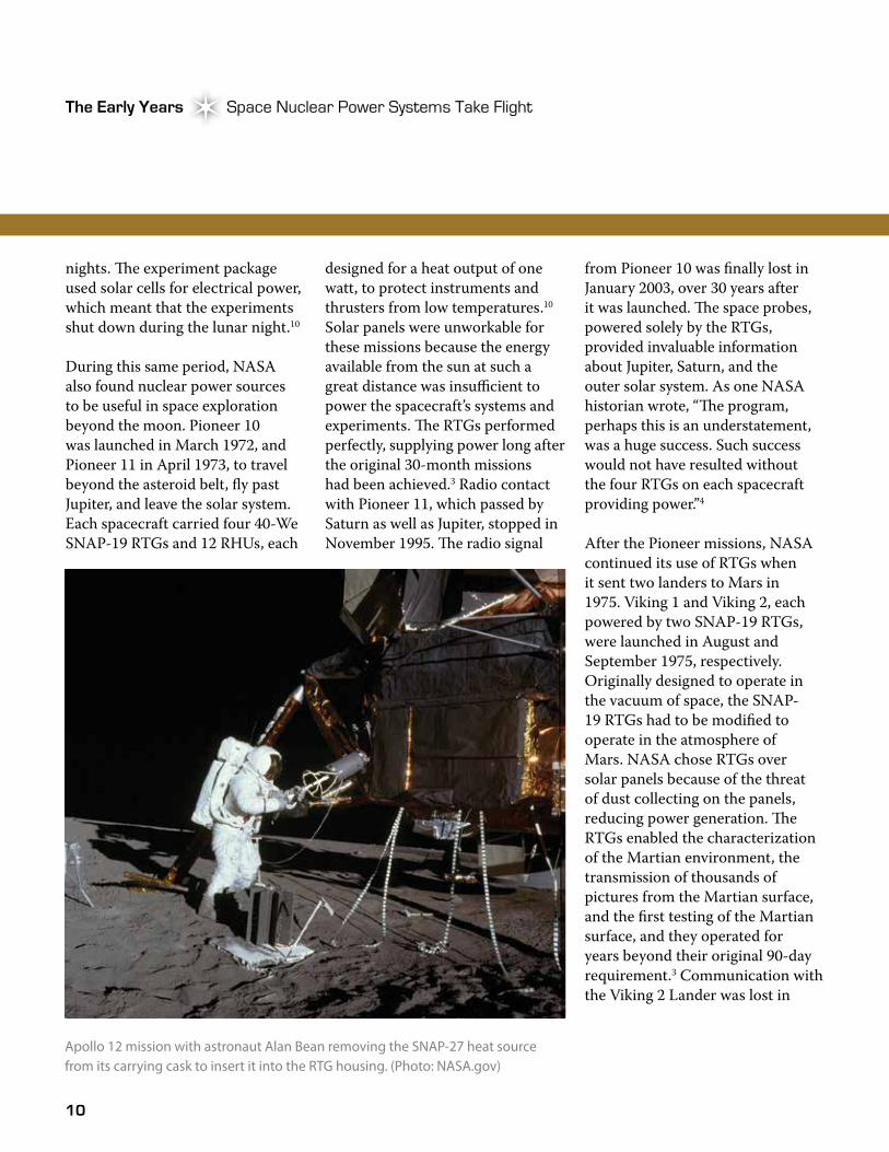
Apollo 12 mission with astronaut Alan Bean removing the SNAP-27 heat source from its carrying cask to insert it into the RTG housing. (Photo: NASA.gov)
11
Atomic Power in Space II Chapter 1Atomic Power in Space II Chapter 1
April 1980, and the Viking 1 Lander in November 1982.11
As RTGs provided power for NASA missions throughout the 1970s, the technology again found application aboard a Navy navigation satellite in 1972. In the first of a series of three experiments designed to test a radiation-hardened satellite and demonstrate other improvements, the Transit-RTG was used aboard the TRIAD experimental satellite launched on September 2, 1972, from Vandenberg Air Force Base. �e Transit RTG used a SNAP-19 heat source to provide approximately 37 We as the primary power source for the satellite. �e system operated as designed for about one month, at which time a telemetry-converter failure precluded further monitoring of the RTG power level. Continued operation of the satellite for several years thereafter, however, indicated the RTG continued to provide power.10
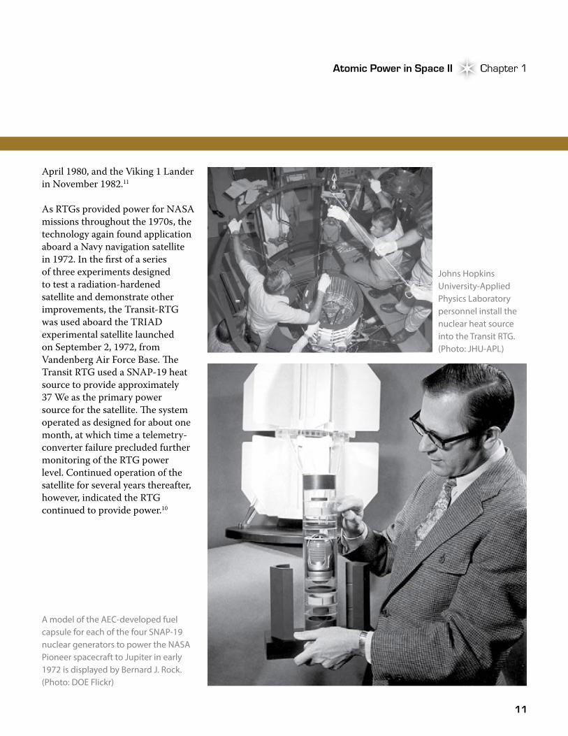
A model of the AEC-developed fuel capsule for each of the four SNAP-19 nuclear generators to power the NASA Pioneer spacecraft to Jupiter in early 1972 is displayed by Bernard J. Rock. (Photo: DOE Flickr)
Johns Hopkins University-Applied Physics Laboratory personnel install the nuclear heat source into the Transit RTG. (Photo: JHU-APL)
12
The Early Years Space Nuclear Power Systems Take FlightThe Early Years Space Nuclear Power Systems Take Flight
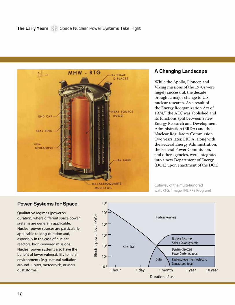
A Changing Landscape
While the Apollo, Pioneer, and Viking missions of the 1970s were hugely successful, the decade brought a major change to U.S. nuclear research. As a result of the Energy Reorganization Act of 1974,12 the AEC was abolished and its functions split between a new Energy Research and Development Administration (ERDA) and the Nuclear Regulatory Commission. Two years later, ERDA, along with the Federal Energy Administration, the Federal Power Commission, and other agencies, were integrated into a new Department of Energy (DOE) upon enactment of the DOE
Cutaway of the multi-hundred watt RTG. (Image: INL RPS Program)
104
105
103
102
Elec
tric
pow
er le
vel (
kWe)
101
100
10-1
1 hour 1 day 1 month
Duration of use
Nuclear Reactors
Solar
Nuclear ReactorsSolar+Solar Dynamic
Dynamic IsotopePower Systems, Solar
Radioisotope ThermoelectricGenerators, Solar
Chemical
1 year 10 years
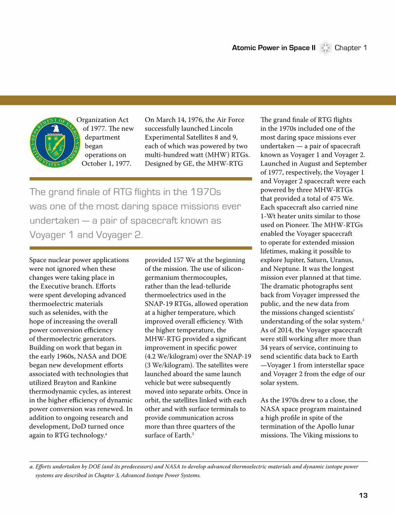
Power Systems for Space
Qualitative regimes (power vs. duration) where di�erent space power systems are generally applicable. Nuclear power sources are particularly applicable to long-duration and, especially in the case of nuclear reactors, high-powered missions. Nuclear power systems also have the bene�t of lower vulnerability to harsh environments (e.g., natural radiation around Jupiter, meteoroids, or Mars dust storms).
13
Atomic Power in Space II Chapter 1Atomic Power in Space II Chapter 1
Organization Act of 1977. �e new department began operations on
October 1, 1977.
Space nuclear power applications were not ignored when these changes were taking place in the Executive branch. Efforts were spent developing advanced thermoelectric materials such as selenides, with the hope of increasing the overall power conversion efficiency of thermoelectric generators. Building on work that began in the early 1960s, NASA and DOE began new development efforts associated with technologies that utilized Brayton and Rankine thermodynamic cycles, as interest in the higher efficiency of dynamic power conversion was renewed. In addition to ongoing research and development, DoD turned once again to RTG technology.a
On March 14, 1976, the Air Force successfully launched Lincoln Experimental Satellites 8 and 9, each of which was powered by two multi-hundred watt (MHW) RTGs. Designed by GE, the MHW-RTG
provided 157 We at the beginning of the mission. �e use of silicon-germanium thermocouples, rather than the lead-telluride thermoelectrics used in the SNAP-19 RTGs, allowed operation at a higher temperature, which improved overall efficiency. With the higher temperature, the MHW-RTG provided a significant improvement in specific power (4.2 We/kilogram) over the SNAP-19 (3 We/kilogram). �e satellites were launched aboard the same launch vehicle but were subsequently moved into separate orbits. Once in orbit, the satellites linked with each other and with surface terminals to provide communication across more than three quarters of the surface of Earth.3
�e grand finale of RTG flights in the 1970s included one of the most daring space missions ever undertaken — a pair of spacecraft known as Voyager 1 and Voyager 2. Launched in August and September of 1977, respectively, the Voyager 1 and Voyager 2 spacecraft were each powered by three MHW-RTGs that provided a total of 475 We. Each spacecraft also carried nine 1-Wt heater units similar to those used on Pioneer. �e MHW-RTGs enabled the Voyager spacecraft to operate for extended mission lifetimes, making it possible to explore Jupiter, Saturn, Uranus, and Neptune. It was the longest mission ever planned at that time. �e dramatic photographs sent back from Voyager impressed the public, and the new data from the missions changed scientists’ understanding of the solar system.3
As of 2014, the Voyager spacecraft were still working after more than 34 years of service, continuing to send scientific data back to Earth —Voyager 1 from interstellar space and Voyager 2 from the edge of our solar system.
As the 1970s drew to a close, the NASA space program maintained a high profile in spite of the termination of the Apollo lunar missions. �e Viking missions to
The grand finale of RTG flights in the 1970s was one of the most daring space missions ever undertaken — a pair of spacecraft known as Voyager 1 and Voyager 2.
a. Efforts undertaken by DOE (and its predecessors) and NASA to develop advanced thermoelectric materials and dynamic isotope power systems are described in Chapter 3, Advanced Isotope Power Systems.
14
The Early Years Space Nuclear Power Systems Take FlightThe Early Years Space Nuclear Power Systems Take Flight
Lawrence Radiation Laboratory (LRL), now known as Lawrence Livermore National Laboratory, to develop a nuclear thermal rocket for use in a propulsion system for ballistic missiles.13
Although the AEC laboratories initially worked in parallel, funding limitations led to the consolidation of all reactor work to LASL in early 1957. Ironically, the new LASL effort was named Rover, the name by which the former LRL nuclear rocket division had called itself (LRL was subsequently given responsibility for work on a nuclear ramjet program called Pluto14).
As the new Rover program got underway, the Nuclear Rocket Development Station was developed to support testing of nuclear rockets. �e station was located in the southwest corner of the Nevada Test Site in an area known as Jackass Flats. It served as the center for U.S. nuclear rocket propulsion testing from 1958 to 1973. It became home to an infrastructure that eventually included three reactor test cells/stands; two maintenance, assembly, and disassembly buildings15 (one for reactors and the other for nuclear
Mars and the Voyager missions to the outer planets kept space exploration in the public eye and helped maintain research and development funding. �e advancement of RTG and heat source technology led to safer and more powerful RTGs. However, space radioisotope and reactor power systems were not the only focus for DOE and its predecessors in those early years. In an effort largely parallel to the SNAP program, a considerable effort was also devoted to the development of technology for space-based nuclear thermal propulsion as well as nuclear electric propulsion.
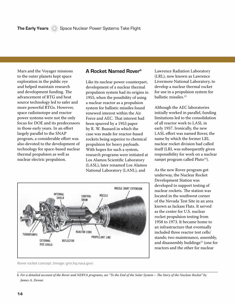
A Rocket Named Roverb
Like its nuclear power counterpart, development of a nuclear thermal propulsion system had its origins in 1955, when the possibility of using a nuclear reactor as a propulsion system for ballistic missiles found renewed interest within the Air Force and AEC. �at interest had been spurred by a 1953 paper by R. W. Bussard in which the case was made for reactor-based rockets being superior to chemical propulsion for heavy payloads. With hopes for such a system, research programs were initiated at Los Alamos Scientific Laboratory (LASL), later renamed Los Alamos National Laboratory (LANL), and
Rover rocket concept. (Image: grin.hq.nasa.gov)
b. For a detailed account of the Rover and NERVA programs, see “To the End of the Solar System – �e Story of the Nuclear Rocket” by James A. Dewar.
15
Atomic Power in Space II Chapter 1Atomic Power in Space II Chapter 1
engines); a technical operations complex; and various support buildings. Reactors were moved between the assembly/disassembly and test facilities via a railroad, humorously referred to as the “Jackass and Western Railroad.” Years later, while speaking of his days managing the Rover program for AEC and NASA, Harold Finger was quick to note that “Jackass Flats is where we did our reactor and engine testing, but it is not descriptive of nor named for the people working on the program here.”16
While the reactor research work was initially performed under the auspices of AEC and the Air Force, defense missions soon gave way to a civilian space focus. By the late 1950s, DoD had dropped further work on nuclear-powered ballistic missiles. Responsibility for nuclear rocket work was subsequently transferred to the newly formed NASA in 1958. While the new space agency assumed overall responsibility for the Rover program, the responsibility for its nuclear aspects remained with AEC. Responsibilities between the two agencies were formally established, as was a joint Space Nuclear Propulsion Office (SNPO), upon the signing of a Memorandum of Understanding in August 1960.16
Over time, the Rover program grew to include five major elements: 1) a reactor and fuel-development effort, called Kiwi, conducted by LASL and Rocketdyne; 2) a nuclear engine development project supported by Aerojet and Westinghouse; 3) development of advanced reactor designs, called Phoebus and Pewee, by LASL; 4) a reactor-in-flight test project run by Lockheed; and 5) a nuclear furnace fuel-testing project operated by LASL. Although each subproject had different objectives, they were all designed to lead to a high-powered nuclear thermal propulsion system with demonstrated reliability. Such a task would prove to be easier said than done, however, when considered in the light of the description offered years later by Glenn T. Seaborg, then Chairman of AEC:
“…What we must do is build a flyable reactor, little larger than an office desk, that will produce the 1,500 megawatt power level of Hoover Dam and achieve this power in a matter of minutes from a cold start. During every minute of its operation, high-speed pumps must force nearly three tons of hydrogen, which has been stored in liquid form at 420°F below zero, past the reactor’s white-hot fuel elements, which reach a temperature of 4,000°F. And this entire system must be capable of operating for hours and of being turned off and restarted with great reliability.”17
Ground Testing the Kiwi Reactors
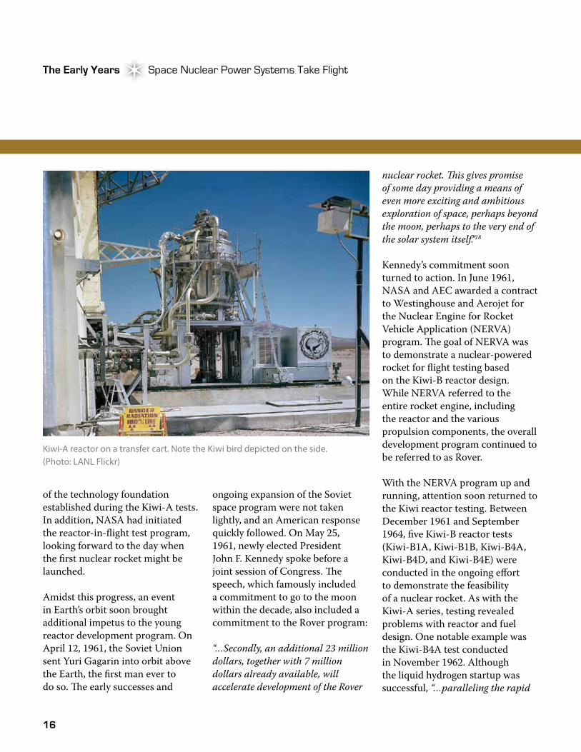
�e first step toward a nuclear thermal propulsion system involved a series of reactor tests called Kiwi, named after the flightless bird because they were only intended for ground testing and not for flight. �e Kiwi tests were designed to demonstrate concept feasibility and basic nuclear rocket reactor technology such as high-temperature fuels and long-life fuel elements. �e Kiwi reactors were designed to demonstrate reactor and fuel feasibility first at a power level of 100 megawatts of thermal power (MWt) (Kiwi-A reactor series) and then at a power level of 1,000 MWt (Kiwi-B reactor series). To that end, the Kiwi test series sought to establish basic testing procedures, demonstrate that a high-power-density reactor could heat a propellant quickly and to high temperatures, and determine material interactions at the high operating temperatures.
From July 1959 to October 1960, three Kiwi-A test reactors (Kiwi-A, Kiwi-A’ [A-prime], and Kiwi-A3) were tested. Although testing revealed problems in reactor and fuel design, the problems were addressed and the feasibility of a 100-MWt reactor design had been demonstrated. By the end of 1960, LASL had also completed the first Kiwi-B reactor design using much
16
The Early Years Space Nuclear Power Systems Take FlightThe Early Years Space Nuclear Power Systems Take Flight
of the technology foundation established during the Kiwi-A tests. In addition, NASA had initiated the reactor-in-flight test program, looking forward to the day when the first nuclear rocket might be launched.
Amidst this progress, an event in Earth’s orbit soon brought additional impetus to the young reactor development program. On April 12, 1961, the Soviet Union sent Yuri Gagarin into orbit above the Earth, the first man ever to do so. �e early successes and
nuclear rocket. �is gives promise of some day providing a means of even more exciting and ambitious exploration of space, perhaps beyond the moon, perhaps to the very end of the solar system itself.”18
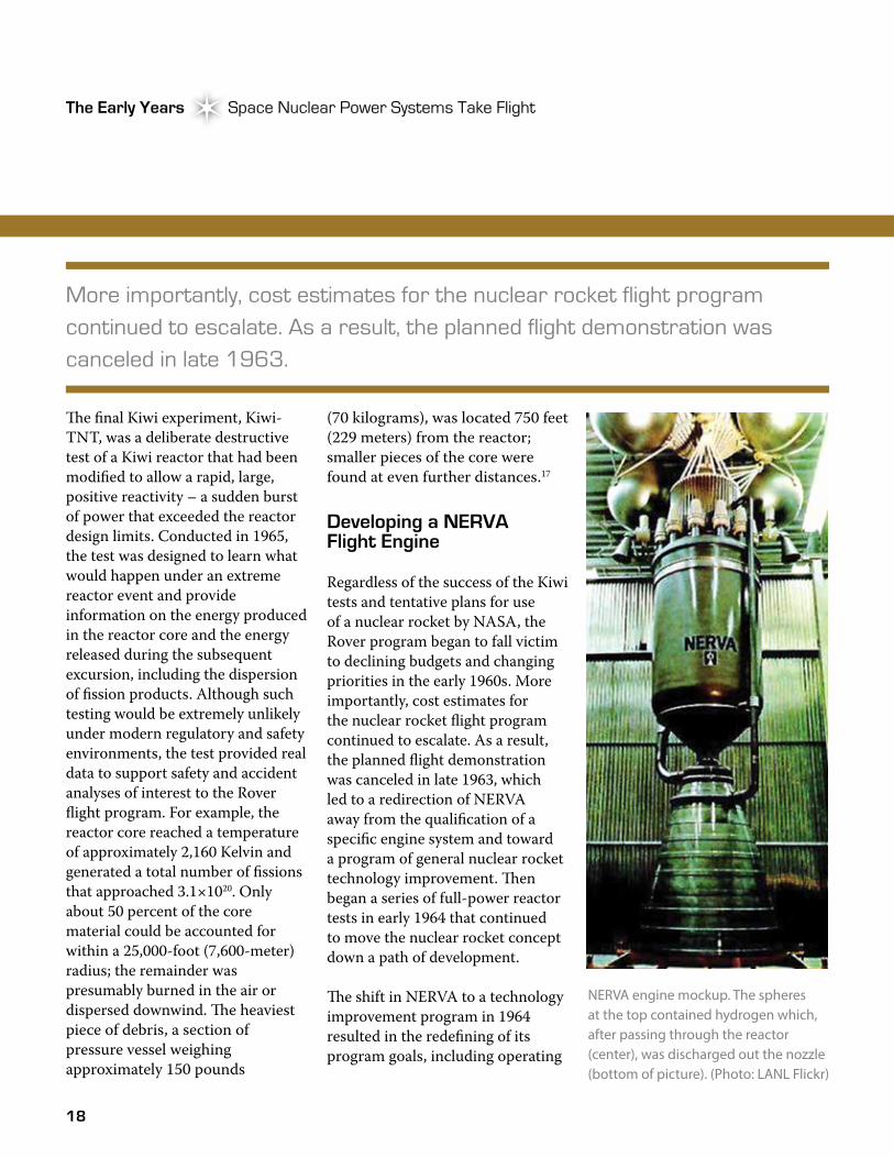
Kennedy’s commitment soon turned to action. In June 1961, NASA and AEC awarded a contract to Westinghouse and Aerojet for the Nuclear Engine for Rocket Vehicle Application (NERVA) program. �e goal of NERVA was to demonstrate a nuclear-powered rocket for flight testing based on the Kiwi-B reactor design. While NERVA referred to the entire rocket engine, including the reactor and the various propulsion components, the overall development program continued to be referred to as Rover.
With the NERVA program up and running, attention soon returned to the Kiwi reactor testing. Between December 1961 and September 1964, five Kiwi-B reactor tests (Kiwi-B1A, Kiwi-B1B, Kiwi-B4A, Kiwi-B4D, and Kiwi-B4E) were conducted in the ongoing effort to demonstrate the feasibility of a nuclear rocket. As with the Kiwi-A series, testing revealed problems with reactor and fuel design. One notable example was the Kiwi-B4A test conducted in November 1962. Although the liquid hydrogen startup was successful, “…paralleling the rapid
Kiwi-A reactor on a transfer cart. Note the Kiwi bird depicted on the side. (Photo: LANL Flickr)
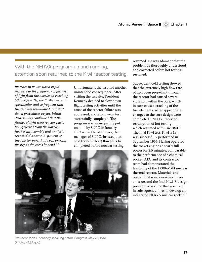
ongoing expansion of the Soviet space program were not taken lightly, and an American response quickly followed. On May 25, 1961, newly elected President John F. Kennedy spoke before a joint session of Congress. �e speech, which famously included a commitment to go to the moon within the decade, also included a commitment to the Rover program:
“…Secondly, an additional 23 million dollars, together with 7 million dollars already available, will accelerate development of the Rover
17
Atomic Power in Space II Chapter 1Atomic Power in Space II Chapter 1
increase in power was a rapid increase in the frequency of flashes of light from the nozzle; on reaching 500 megawatts, the flashes were so spectacular and so frequent that the test was terminated and shut down procedures began. Initial disassembly confirmed that the flashes of light were reactor parts being ejected from the nozzle; further disassembly and analysis revealed that over 90 percent of the reactor parts had been broken, mostly at the core’s hot end.”17
Unfortunately, the test had another unintended consequence. After visiting the test site, President Kennedy decided to slow down flight testing activities until the cause of the reactor failure was addressed, and a follow-on test successfully completed. �e program was subsequently put on hold by SNPO in January 1963 when Harold Finger, then manager of SNPO, insisted that cold (non-nuclear) flow tests be completed before nuclear testing
With the NERVA program up and running, attention soon returned to the Kiwi reactor testing.
resumed. He was adamant that the problem be thoroughly understood and corrected before hot testing resumed.
Subsequent cold testing showed that the extremely high flow rate of hydrogen propellant through the reactor had caused severe vibration within the core, which in turn caused cracking of the fuel elements. After appropriate changes to the core design were completed, SNPO authorized resumption of hot testing, which resumed with Kiwi-B4D. �e final Kiwi test, Kiwi-B4E, was successfully performed in September 1964. Having operated the rocket engine at nearly full power for 2.5 minutes, comparable to the performance of a chemical rocket, AEC and its contractor team had demonstrated the feasibility of the 1,000-MWt nuclear thermal reactor. Materials and operational issues were no longer an issue, and the final Kiwi-B design provided a baseline that was used in subsequent efforts to develop an integrated NERVA nuclear rocket.17
President John F. Kennedy speaking before Congress, May 25, 1961. (Photo: NASA.gov)
18
The Early Years Space Nuclear Power Systems Take FlightThe Early Years Space Nuclear Power Systems Take Flight
�e final Kiwi experiment, Kiwi-TNT, was a deliberate destructive test of a Kiwi reactor that had been modified to allow a rapid, large, positive reactivity – a sudden burst of power that exceeded the reactor design limits. Conducted in 1965, the test was designed to learn what would happen under an extreme reactor event and provide information on the energy produced in the reactor core and the energy released during the subsequent excursion, including the dispersion of fission products. Although such testing would be extremely unlikely under modern regulatory and safety environments, the test provided real data to support safety and accident analyses of interest to the Rover flight program. For example, the reactor core reached a temperature of approximately 2,160 Kelvin and generated a total number of fissions that approached 3.1×10²⁰. Only about 50 percent of the core material could be accounted for within a 25,000-foot (7,600-meter) radius; the remainder was presumably burned in the air or dispersed downwind. �e heaviest piece of debris, a section of pressure vessel weighing approximately 150 pounds
NERVA engine mockup. The spheres at the top contained hydrogen which, after passing through the reactor (center), was discharged out the nozzle (bottom of picture). (Photo: LANL Flickr)
More importantly, cost estimates for the nuclear rocket flight program continued to escalate. As a result, the planned flight demonstration was canceled in late 1963.
(70 kilograms), was located 750 feet (229 meters) from the reactor; smaller pieces of the core were found at even further distances.17
Developing a NERVA Flight Engine
Regardless of the success of the Kiwi tests and tentative plans for use of a nuclear rocket by NASA, the Rover program began to fall victim to declining budgets and changing priorities in the early 1960s. More importantly, cost estimates for the nuclear rocket flight program continued to escalate. As a result, the planned flight demonstration was canceled in late 1963, which led to a redirection of NERVA away from the qualification of a specific engine system and toward a program of general nuclear rocket technology improvement. �en began a series of full-power reactor tests in early 1964 that continued to move the nuclear rocket concept down a path of development.
�e shift in NERVA to a technology improvement program in 1964 resulted in the redefining of its program goals, including operating
19
Atomic Power in Space II Chapter 1Atomic Power in Space II Chapter 1
for 60 minutes at full power; restarting at any point in the reactor’s life cycle; demonstrating rapid temperature increases and decreases; cooling down using only liquid hydrogen; startup of the engine without an external power source; and determination of system operational margins, limits, and reliability.17
Major contractors involved in the NERVA program included the Rocketdyne Division of North American Aviation (later part of Boeing), which was responsible for building a liquid hydrogen turbopump and nozzle; Aerojet, responsible for a flow control system; ACF-Erco, responsible for manufacturing the pressure shell; and EG&G, Inc., which
was responsible for producing instrumentation. Construction of the nuclear reactor was the responsibility of the Westinghouse Electric Corporation Astronuclear Laboratory.17
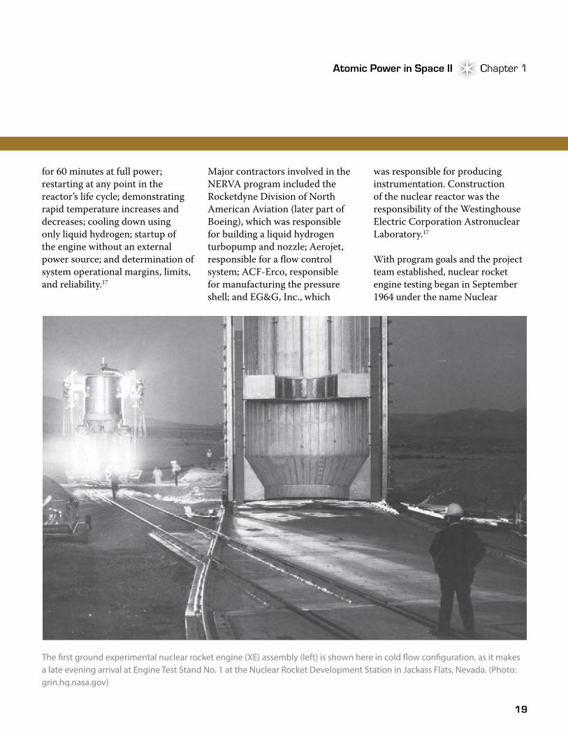
With program goals and the project team established, nuclear rocket engine testing began in September 1964 under the name Nuclear
The �rst ground experimental nuclear rocket engine (XE) assembly (left) is shown here in cold �ow con�guration, as it makes a late evening arrival at Engine Test Stand No. 1 at the Nuclear Rocket Development Station in Jackass Flats, Nevada. (Photo: grin.hq.nasa.gov)
20
The Early Years Space Nuclear Power Systems Take FlightThe Early Years Space Nuclear Power Systems Take Flight
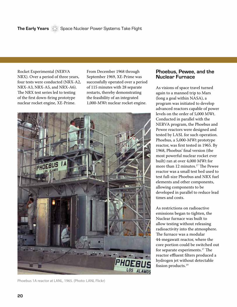
Rocket Experimental (NERVA NRX). Over a period of three years, four tests were conducted (NRX-A2, NRX-A3, NRX-A5, and NRX-A6). �e NRX test series led to testing of the first down-firing prototype nuclear rocket engine, XE-Prime.
From December 1968 through September 1969, XE-Prime was successfully operated over a period of 115 minutes with 28 separate restarts, thereby demonstrating the feasibility of an integrated 1,000-MWt nuclear rocket engine.
Phoebus 1A reactor at LANL, 1965. (Photo: LANL Flickr)
Phoebus, Pewee, and the Nuclear Furnace
As visions of space travel turned again to a manned trip to Mars (long a goal within NASA), a program was initiated to develop advanced reactors capable of power levels on the order of 5,000 MWt. Conducted in parallel with the NERVA program, the Phoebus and Pewee reactors were designed and tested by LASL for such operation. Phoebus, a 5,000-MWt prototype reactor, was first tested in 1965. By 1968, Phoebus’ final version (the most powerful nuclear rocket ever built) ran at over 4,000 MWt for more than 12 minutes.17 �e Pewee reactor was a small test bed used to test full-size Phoebus and NRX fuel elements and other components, allowing components to be developed in parallel to reduce lead times and costs.
As restrictions on radioactive emissions began to tighten, the Nuclear furnace was built to allow testing without releasing radioactivity into the atmosphere. �e furnace was a modular 44-megawatt reactor, where the core portion could be switched out for separate experiments.17 �e reactor effluent filters produced a hydrogen jet without detectable fission products.19
21
Atomic Power in Space II Chapter 1Atomic Power in Space II Chapter 1
Accomplishments and the Face of Changing National Priorities
As the Rover program turned the corner on a new decade, it soon found itself facing a very different future. After the urgency of reaching the moon passed and the Apollo missions ended in 1972, it became clear that a manned Mars mission wouldn’t be the next step. Due to changing priorities on national budgets, further development of the NERVA nuclear rocket was terminated in the fiscal year 1972 budget.
From 1955 to 1971, the United States spent approximately $3.5 billion (in 1960 dollars) on the Rover and NERVA programs19 (compared with $19.4 billion spent on the Apollo program from 1960 through 197320). During that period, 17 reactors, one nuclear safety reactor, and two ground experimental engines were developed and tested. �e feasibility of a solid graphite reactor/nuclear rocket engine had been clearly established “...at temperature, pressure, power levels, and durations commensurate with today’s [1991] propulsion system requirements...” �e technology had also been demonstrated to an extent such that “…future nuclear propulsion development associated with new space exploration initiatives can be directed to
Against the backdrop of such technical accomplishments, lessons had been learned and provided a foundation for future development.
incremental performance, reliability and lifetime improvements.” In addition, the Rover program demonstrated a model by which two government agencies could effectively manage a major technology development program.21
Looking Forward
As the first 30 years of space nuclear power drew to a close in the mid-1980s, DOE, NASA, and others had many reasons to celebrate. �irty-five RTGs, ranging in power from the small 2.7-We SNAP-3B unit to the 157-We MHW-RTG, had been successfully launched into space to power lunar experiments and planetary orbiters, while other spacecraft were on their way to the end of the solar system. Multiple space RPS concepts had been developed and tested under the SNAP program, and one space nuclear reactor power system had been successfully placed into Earth’s orbit. On the nuclear rocket front, the feasibility of nuclear thermal propulsion had been successfully demonstrated, evolving from initial testing of the
100-MWt Kiwi-A reactors to the 4,000-MWt NERVA XE reactor through 20 different reactor tests.
Against the backdrop of such technical accomplishments, lessons had been learned that
provided a foundation for future development. In addition, an entire infrastructure had been built across the DOE complex to support ongoing development, testing, and use of space nuclear systems. Most importantly, a new technical discipline had been defined, an industry established, and a foundation laid that would allow a new generation of space nuclear technologists to carry the torch of space nuclear power into another 30 years of testing, development, and accomplishments.
22
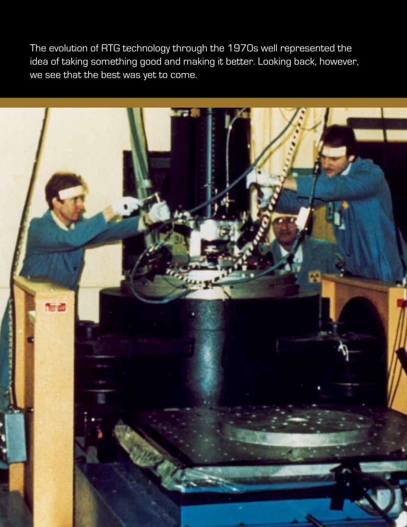
The evolution of RTG technology through the 1970s well represented the idea of taking something good and making it better. Looking back, however, we see that the best was yet to come.
23Photo Credit
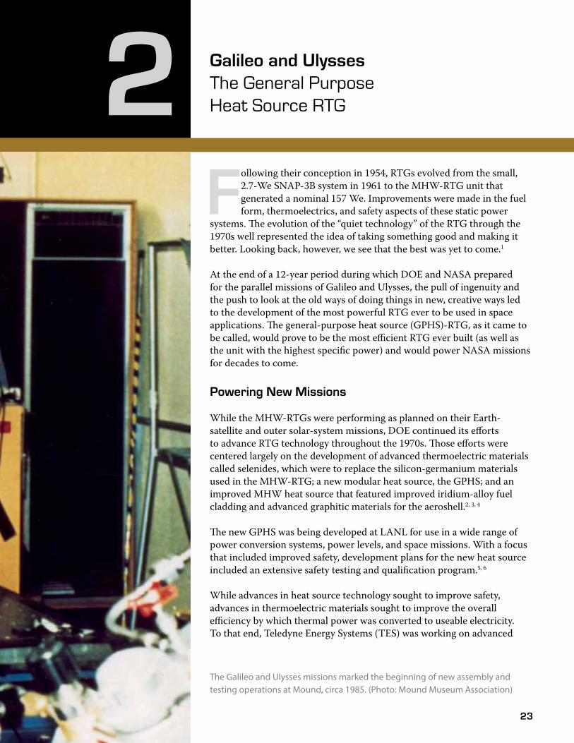
Galileo and Ulysses The General Purpose Heat Source RTG2F
ollowing their conception in 1954, RTGs evolved from the small, 2.7-We SNAP-3B system in 1961 to the MHW-RTG unit that generated a nominal 157 We. Improvements were made in the fuel form, thermoelectrics, and safety aspects of these static power
systems. �e evolution of the “quiet technology” of the RTG through the 1970s well represented the idea of taking something good and making it better. Looking back, however, we see that the best was yet to come.1
At the end of a 12-year period during which DOE and NASA prepared for the parallel missions of Galileo and Ulysses, the pull of ingenuity and the push to look at the old ways of doing things in new, creative ways led to the development of the most powerful RTG ever to be used in space applications. �e general-purpose heat source (GPHS)-RTG, as it came to be called, would prove to be the most efficient RTG ever built (as well as the unit with the highest specific power) and would power NASA missions for decades to come.
Powering New Missions
While the MHW-RTGs were performing as planned on their Earth-satellite and outer solar-system missions, DOE continued its efforts to advance RTG technology throughout the 1970s. �ose efforts were centered largely on the development of advanced thermoelectric materials called selenides, which were to replace the silicon-germanium materials used in the MHW-RTG; a new modular heat source, the GPHS; and an improved MHW heat source that featured improved iridium-alloy fuel cladding and advanced graphitic materials for the aeroshell.2, 3, 4
�e new GPHS was being developed at LANL for use in a wide range of power conversion systems, power levels, and space missions. With a focus that included improved safety, development plans for the new heat source included an extensive safety testing and qualification program.5, 6
While advances in heat source technology sought to improve safety, advances in thermoelectric materials sought to improve the overall efficiency by which thermal power was converted to useable electricity. To that end, Teledyne Energy Systems (TES) was working on advanced
The Galileo and Ulysses missions marked the beginning of new assembly and testing operations at Mound, circa 1985. (Photo: Mound Museum Association)
24
Galileo and Ulysses The General Purpose Heat Source RTGGalileo and Ulysses
power conversion technology using selenide-based thermoelectric materials under development at the 3M Corporation. Early laboratory-scale testing of the selenide materials indicated potential conversion efficiencies of at least 10 percent, which represented a hopeful improvement of approximately 50 percent above that of the silicon-germanium materials used in the MHW-RTG. Amidst such favorable expectations, DOE planned to develop a new RTG (called the selenide isotope generator [SIG]) that would eventually utilize the new selenide thermoelectric materials and the new GPHS.7
�e first phase in developing the SIG would combine the selenide thermoelectrics with a MHW heat source for use on a mission that came to be called Galileo (initially called Jupiter Orbiter Probe), named after the 17th-century Italian astronomer who discovered four of Jupiter’s moons. Long-term surveys of Jupiter would be made using an RTG-powered orbiter, while a smaller probe would collect atmospheric and other information about the gas giant during a one-time pass through its atmosphere.8
�e next phase in SIG development would combine the selenide thermoelectrics with the new modular GPHS for use on a multi-national mission originally called the International Solar Polar Mission (ISPM). As conceived, the
mission was a joint effort between NASA and the European Space Agency (ESA) to provide the first polar-orbital survey of the sun. Each agency would supply one spacecraft, both powered by RTGs supplied by DOE, to make scientific measurements above and below the ecliptic —the plane of Earth’s orbit about the sun. Domestic budget pressures in the early 1980s resulted in cancellation of the NASA spacecraft; ESA continued the mission, and it was subsequently renamed Ulysses.9
Despite high hopes for the new selenide thermoelectric materials, by 1979, testing of prototypic selenide thermocouples had uncovered significant material-instability and conversion-efficiency issues. After considering
its options against mission needs and schedules, DOE decided to abandon further development of the selenide materials and return to the proven silicon-germanium unicouples for the needed RTGs. For the Galileo mission,
development of the MHW-RTGs continued but with the proven silicon-germanium thermoelectrics. For the ISPM mission, responsibilities for development of the RTG were subsequently contracted to GE and the new RTG was named (at least briefly) the ISPM, or Solar-Polar, RTG.6
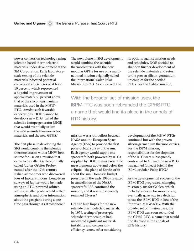
As the developmental success of the ISPM-RTG progressed, changing mission plans for Galileo, which included a desire for more power, eventually gave way to a decision to use the ISPM-RTG in lieu of the improved MHW-RTG. With the broader set of mission uses, the ISPM-RTG was soon rebranded the GPHS-RTG, a name that would find its place in the annals of RTG history.7
With the broader set of mission uses, the ISPM-RTG was soon rebranded the GPHS-RTG, a name that would find its place in the annals of RTG history.
25
Atomic Power in Space II Chapter 2Atomic Power in Space II Chapter 2
As the dust of program and mission planning settled, DOE was responsible for developing the new GPHS-RTG for use on the two missions. Ultimately, three flight-qualified GPHS-RTGs and one spare unit were needed. �e new GPHS, around which the RTG was to be built, was still under development; safety testing and a final design, necessary to demonstrate acceptability for use in space, remained to be completed. In addition, the launch vehicles planned for launching the Galileo and Ulysses spacecraft into space were also still under development. On top of that, the production capability for the silicon germanium unicouples had to be re-established. Years later, the effort to develop the GPHS-RTG would aptly be referred to as a “mission of daring” by many of the individuals directly involved.10
As had been performed previously, DOE completed this mission using a small but diverse group of companies and national laboratories, a unique set of technical capabilities and assembly and test facilities, and a group of highly dedicated individuals committed to program success. An interagency agreement signed by DOE and NASA defined the overall roles and responsibilities of the respective agencies. Responsibility for development of the GPHS-RTG resided with the DOE Office of Special Applications.11
The General Purpose Heat Source
Initial design and development of the new GPHS resided with LANL but was later enhanced by GE and Fairchild. Design of the new heat source included several goals, one of which was the idea of modularity, in which individual modules could be combined to provide the amount of power required by a specific mission. Another goal was to develop a heat source that would be compatible with multiple static and dynamic power conversion systems. A high power density of at least 75 watts (thermal) per pound was also desired. In keeping with the intact re-entry safety philosophy adopted in the 1960s, the primary safety objective was to keep the fuel contained or immobilized to prevent inhalation or ingestion by people. Ultimately, mission planners had to be confident that the public would be protected in case of any foreseeable accident.5,12
�e final GPHS design consisted of a rectangular-shaped carbon-carbon module into which the encapsulated fuel would be placed. �e design included several protective features to guard against explosions, fires, impacts, projectiles, and the heat of Earth re-entry. �ese features included the fuel, iridium-alloy metal cladding, fine-weaved pierced fabric (FWPF), and a carbon-bonded, carbon-fiber sleeve component.
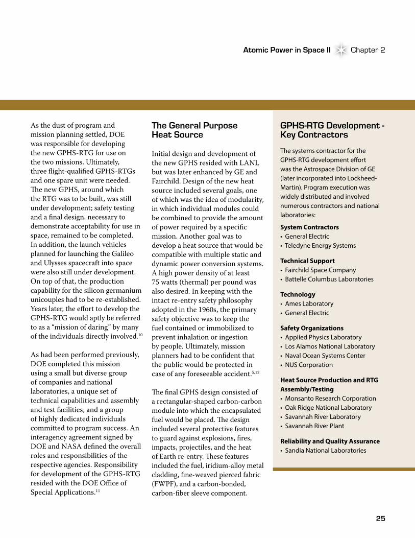
GPHS-RTG Development - Key Contractors
The systems contractor for the GPHS-RTG development e�ort was the Astrospace Division of GE (later incorporated into Lockheed-Martin). Program execution was widely distributed and involved numerous contractors and national laboratories:
System Contractors • General Electric • Teledyne Energy Systems
Technical Support • Fairchild Space Company • Battelle Columbus Laboratories
Technology • Ames Laboratory • General Electric
Safety Organizations • Applied Physics Laboratory • Los Alamos National Laboratory• Naval Ocean Systems Center • NUS Corporation
Heat Source Production and RTG Assembly/Testing • Monsanto Research Corporation• Oak Ridge National Laboratory• Savannah River Laboratory • Savannah River Plant
Reliability and Quality Assurance • Sandia National Laboratories
26
Galileo and Ulysses The General Purpose Heat Source RTGGalileo and Ulysses
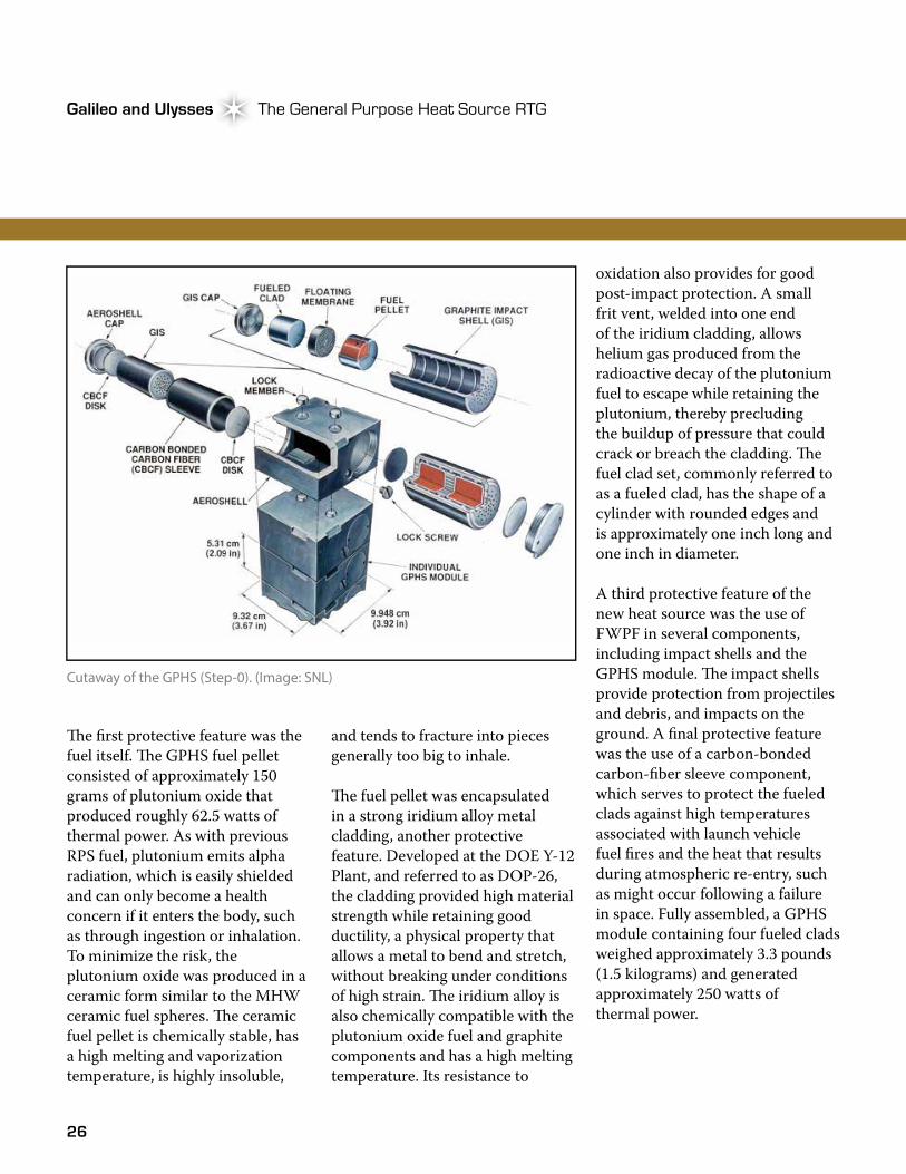
�e first protective feature was the fuel itself. �e GPHS fuel pellet consisted of approximately 150 grams of plutonium oxide that produced roughly 62.5 watts of thermal power. As with previous RPS fuel, plutonium emits alpha radiation, which is easily shielded and can only become a health concern if it enters the body, such as through ingestion or inhalation. To minimize the risk, the plutonium oxide was produced in a ceramic form similar to the MHW ceramic fuel spheres. �e ceramic fuel pellet is chemically stable, has a high melting and vaporization temperature, is highly insoluble,
oxidation also provides for good post-impact protection. A small frit vent, welded into one end of the iridium cladding, allows helium gas produced from the radioactive decay of the plutonium fuel to escape while retaining the plutonium, thereby precluding the buildup of pressure that could crack or breach the cladding. �e fuel clad set, commonly referred to as a fueled clad, has the shape of a cylinder with rounded edges and is approximately one inch long and one inch in diameter.
A third protective feature of the new heat source was the use of FWPF in several components, including impact shells and the GPHS module. �e impact shells provide protection from projectiles and debris, and impacts on the ground. A final protective feature was the use of a carbon-bonded carbon-fiber sleeve component, which serves to protect the fueled clads against high temperatures associated with launch vehicle fuel fires and the heat that results during atmospheric re-entry, such as might occur following a failure in space. Fully assembled, a GPHS module containing four fueled clads weighed approximately 3.3 pounds (1.5 kilograms) and generated approximately 250 watts of thermal power.
Cutaway of the GPHS (Step-0). (Image: SNL)
and tends to fracture into pieces generally too big to inhale.
�e fuel pellet was encapsulated in a strong iridium alloy metal cladding, another protective feature. Developed at the DOE Y-12 Plant, and referred to as DOP-26, the cladding provided high material strength while retaining good ductility, a physical property that allows a metal to bend and stretch, without breaking under conditions of high strain. �e iridium alloy is also chemically compatible with the plutonium oxide fuel and graphite components and has a high melting temperature. Its resistance to
27
Atomic Power in Space II Chapter 2Atomic Power in Space II Chapter 2
The GPHS-RTG
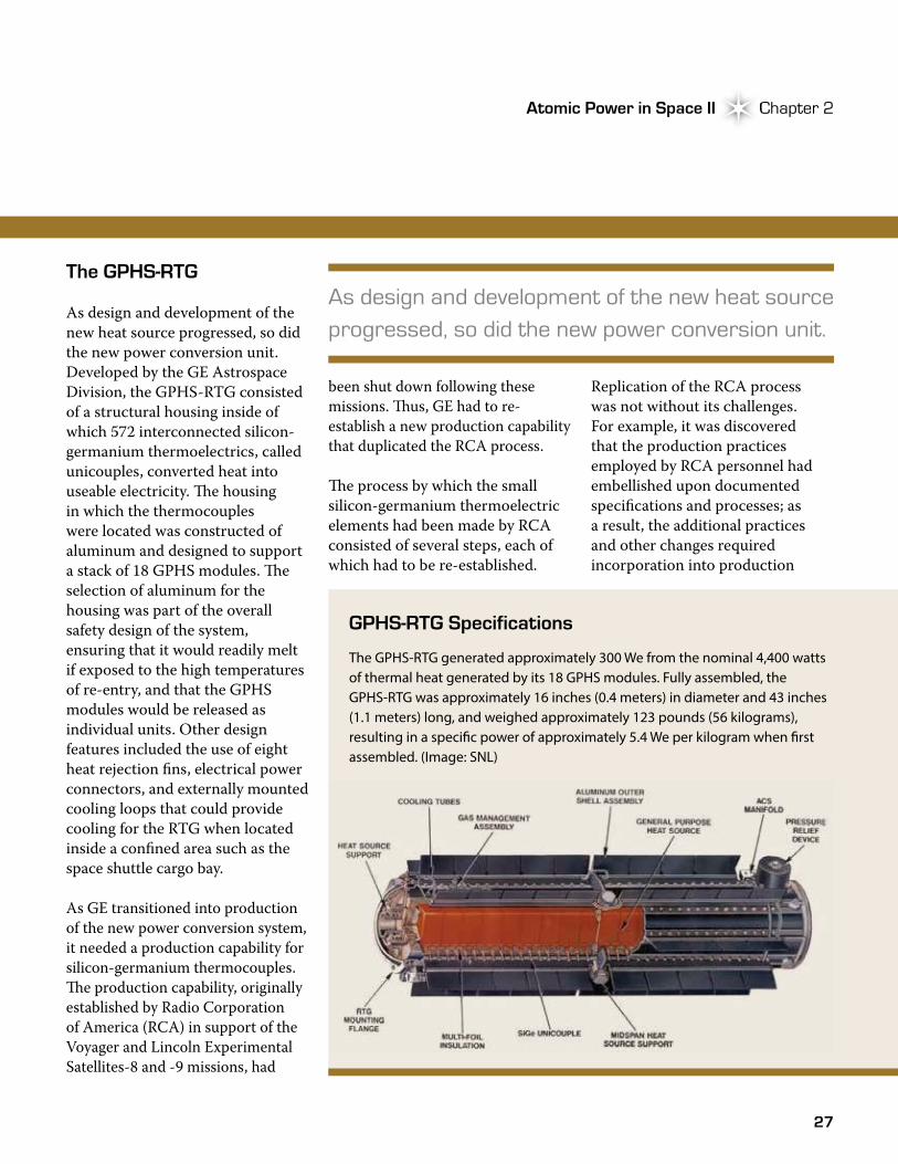
As design and development of the new heat source progressed, so did the new power conversion unit. Developed by the GE Astrospace Division, the GPHS-RTG consisted of a structural housing inside of which 572 interconnected silicon-germanium thermoelectrics, called unicouples, converted heat into useable electricity. �e housing in which the thermocouples were located was constructed of aluminum and designed to support a stack of 18 GPHS modules. �e selection of aluminum for the housing was part of the overall safety design of the system, ensuring that it would readily melt if exposed to the high temperatures of re-entry, and that the GPHS modules would be released as individual units. Other design features included the use of eight heat rejection fins, electrical power connectors, and externally mounted cooling loops that could provide cooling for the RTG when located inside a confined area such as the space shuttle cargo bay.
As GE transitioned into production of the new power conversion system, it needed a production capability for silicon-germanium thermocouples. �e production capability, originally established by Radio Corporation of America (RCA) in support of the Voyager and Lincoln Experimental Satellites-8 and -9 missions, had
been shut down following these missions. �us, GE had to re-establish a new production capability that duplicated the RCA process.
�e process by which the small silicon-germanium thermoelectric elements had been made by RCA consisted of several steps, each of which had to be re-established.
As design and development of the new heat source progressed, so did the new power conversion unit.
Replication of the RCA process was not without its challenges. For example, it was discovered that the production practices employed by RCA personnel had embellished upon documented specifications and processes; as a result, the additional practices and other changes required incorporation into production
GPHS-RTG Specifications
The GPHS-RTG generated approximately 300 We from the nominal 4,400 watts of thermal heat generated by its 18 GPHS modules. Fully assembled, the GPHS-RTG was approximately 16 inches (0.4 meters) in diameter and 43 inches (1.1 meters) long, and weighed approximately 123 pounds (56 kilograms), resulting in a speci�c power of approximately 5.4 We per kilogram when �rst assembled. (Image: SNL)
28
Galileo and Ulysses The General Purpose Heat Source RTGGalileo and Ulysses
procedures to improve process rigor and control.13 For the four GPHS-RTGs planned for the Galileo and Ulysses missions, over 2,000 individual unicouples were eventually fabricated for use in the units. Additional unicouples were also produced for the engineering and qualification units used to demonstrate readiness of the RTG for flight use, as well as for an unfueled spare converter.
Along with re-establishing the production process for the unicouples, GE conducted a rigorous testing program to address all facets of the power conversion system and the fully assembled RTG. Testing was performed in a progressive manner, beginning with individual unicouples followed by 18-couple modules. �e unicouple testing was followed by tests of full-scale component engineering test units for structural, thermal, and material properties, which demonstrated the design of an electrically heated engineering unit. Non-nuclear testing of the engineering unit included thermal and vibration tests to ensure the thermoelectrics and other components of the power conversion system would properly operate. Testing culminated with a nuclear-heated qualification unit, which served to verify that the GPHS-RTG would operate as designed and meet all mission requirements.14
Guided by Safety
Integral to the design and development of the GPHS-RTG was a rigorous safety testing program, conducted to determine how the heat source would respond to various postulated accident conditions that might occur during launch or once in orbit. For example, a launch vehicle explosion on the launch pad or during ascent might subject the RTG and its heat sources to high-pressure shock waves from liquid and solid fires, launch vehicle and spacecraft fragment impacts, and ground impacts onto steel, concrete, or sand. A late launch accident, such as one involving orbital or suborbital re-entry, might also subject the RTG and its heat sources to high temperatures and subsequent ground impacts. �e modular design of the GPHS modules also ensured that the chances of impacts from spacecraft debris would be very low, if not impossible. Subsequent safety testing at LANL and SNL demonstrated the protective safety features of the GPHS module under a variety of postulated accident scenarios.5, 15
�e testing was planned and conducted against a backdrop of evolving mission plans that centered on a new NASA launch vehicle. For the Galileo and Ulysses missions, NASA planned to launch the spacecraft aboard its
new space transportation system (STS), which included the space shuttle. Once the shuttle reached its parking orbit, the spacecraft would be released from its cargo bay, and an upper-stage propulsion system would be used to propel the spacecraft towards its destination.
In the evolution of planning associated with the use of the new STS, which was then under development, a decision regarding the specific upper-stage launch vehicle to be used for Galileo and Ulysses changed frequently, alternating between a solid-fuel inertial upper stage and a Centaur rocket that was fueled with liquid hydrogen/liquid oxygen. Each upper-stage vehicle had unique hazards and characteristics that influenced development of the requisite safety analysis. As a result of ongoing changes regarding which upper-stage vehicle to use, a preliminary safety analysis was based on use of an inertial upper stage but was later revised to reflect a Centaur system. As discussed later in the chapter, this would not be the last change in the launch system to be used.15
While upper-stage vehicle planning perturbations were frustrating, tests were nonetheless devised to simulate a broad range of possible pressures, temperatures, and other environmental conditions. In a series of safety verification tests
29
Atomic Power in Space II Chapter 2Atomic Power in Space II Chapter 2
A Formal and Exhaustive Safety Review Process
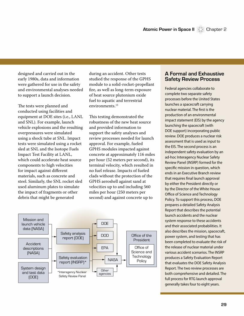
Federal agencies collaborate to complete two separate safety processes before the United States launches a spacecraft carrying nuclear material. The �rst is the production of an environmental impact statement (EIS) by the agency launching the spacecraft (with DOE support) incorporating public review. DOE produces a nuclear risk assessment that is used as input to the EIS. The second process is an independent safety evaluation by an ad-hoc Interagency Nuclear Safety Review Panel (INSRP) formed for the speci�c mission in question, which ends in an Executive Branch review that requires �nal launch approval by either the President directly or by the Director of the White House O�ce of Science and Technology Policy. To support this process, DOE prepares a detailed Safety Analysis Report that describes the potential launch accidents and the nuclear system response to these accidents and their associated probabilities. It also describes the mission, spacecraft, power system, and testing that has been completed to evaluate the risk of the release of nuclear material under various accident scenarios. The INSRP produces a Safety Evaluation Report that evaluates the DOE Safety Analysis Report. The two review processes are both comprehensive and detailed. The full process for RTG launch approval generally takes four to eight years.
designed and carried out in the early 1980s, data and information were gathered for use in the safety and environmental analyses needed to support a launch decision.
�e tests were planned and conducted using facilities and equipment at DOE sites (i.e., LANL and SNL). For example, launch vehicle explosions and the resulting overpressures were simulated using a shock tube at SNL. Impact tests were simulated using a rocket sled at SNL and the Isotope Fuels Impact Test Facility at LANL, which could accelerate heat source components to high velocities for impact against different materials, such as concrete and steel. Similarly, the SNL rocket sled used aluminum plates to simulate the impact of fragments or other debris that might be generated
during an accident. Other tests studied the response of the GPHS module to a solid-rocket-propellant fire, as well as long-term exposure of heat source plutonium oxide fuel to aquatic and terrestrial environments.15
�is testing demonstrated the robustness of the new heat source and provided information to support the safety analyses and review processes needed for launch approval. For example, fueled GPHS modules impacted against concrete at approximately 116 miles per hour (52 meters per second), its terminal velocity, which resulted in no fuel release. Impacts of fueled clads without the protection of the GPHS aeroshell against sand at velocities up to and including 560 miles per hour (250 meters per second) and against concrete up to
Office of thePresident
Safety analysisreport (DOE)
Safety evaluationreport (INSRP)*
*Interagency Nuclear Safety Review Panel
DOE
DOD
EPA
NASA
Otheragencies
Mission andlaunch vehicledata (NASA)
Office ofScience andTechnology
Policy
Accidentdescriptions
(NASA)
System designand test data
(DOE)
30
Galileo and Ulysses The General Purpose Heat Source RTGGalileo and Ulysses
134 miles per hour (60 meters per second) yielded similar results. No releases occurred as a result of explosion over pressure when tested, as did testing at over pressures up to 2,200 pounds per square inch (psi). At the conclusion of the safety testing, design, and development efforts, the new GPHS was finally ready for production and use.15
Production Takes Center Stage
�e effort to produce the GPHS-RTGs and their heat sources was widely distributed and involved numerous DOE contractors and national laboratories. For example, the iridium-alloy raw materials used to fabricate the cladding and frit vents were produced at ORNL. Fabrication of the iridium cladding and frit vents was performed at the Mound Laboratory. Fabrication and encapsulation of the plutonium oxide fuel pellets was performed in the Plutonium Fuel Fabrication Facility at Savannah River Site (SRS). �e encapsulated fuel pellets were then transferred to Mound, where they were encapsulated in the graphitic components during GPHS module assembly operations.
�e Galileo and Ulysses missions brought new opportunities for the space nuclear power
system workforce at Mound. In the late 1970s, DOE decided to transfer RTG assembly and testing operations from its system contractors, GE and TES, to Mound. Although radioisotope heat source assembly and other related operations had been conducted at Mound for over 30 years, the new RTG assembly and testing work required that a facility, equipment, operations, and personnel be in place and ready to support the planned launch dates. �e new operation was located in Building 50, the RTG Assembly and Testing Facility, which had been used for other activities since the early 1970s.
Modifications to accommodate the new RTG operations began in the early 1980s and were completed in 1983. Equipment was received and set up, procedures were developed, and workers were trained to accommodate the new assembly and testing operations.16 It was a hectic time, and the pressure to have RTGs ready for the aggressive launch schedule meant long hours and work weeks for those involved. As Wayne Amos of
Mound recalled years later, “We had technical problems which led to schedule issues and working 24 hours a day, seven days a week. But it was a good group and we all worked well together...”17
After months of preparation, training, and reviews, Mound finally put its new RTG assembly and testing capability to work. In April 1983, Mound received a GPHS-RTG qualification unit, designated Q-1, for fueling and testing. Assembly of the qualification unit was performed in the new Inert Atmosphere Assembly Chamber, where operators assembled the stack of 18 fueled GPHS modules and inserted the stack into the generator. �e RTG was then sealed and backfilled with an inert gas, which served to protect the thermoelectrics from deleterious effects of atmospheric oxygen during storage and testing operations.
The Galileo and Ulysses missions brought new opportunities for the space nuclear power system workforce at Mound.
31
Atomic Power in Space II Chapter 2Atomic Power in Space II Chapter 2
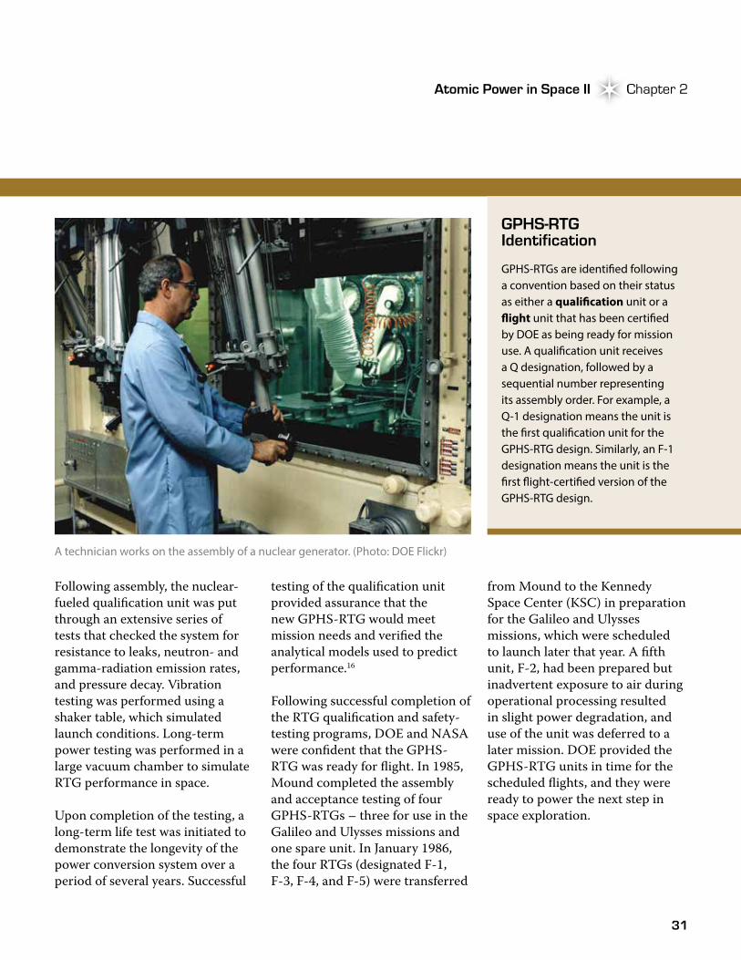
GPHS-RTG Identification
GPHS-RTGs are identi�ed following a convention based on their status as either a quali�cation unit or a �ight unit that has been certi�ed by DOE as being ready for mission use. A quali�cation unit receives a Q designation, followed by a sequential number representing its assembly order. For example, a Q-1 designation means the unit is the �rst quali�cation unit for the GPHS-RTG design. Similarly, an F-1 designation means the unit is the �rst �ight-certi�ed version of the GPHS-RTG design.
A technician works on the assembly of a nuclear generator. (Photo: DOE Flickr)
Following assembly, the nuclear-fueled qualification unit was put through an extensive series of tests that checked the system for resistance to leaks, neutron- and gamma-radiation emission rates, and pressure decay. Vibration testing was performed using a shaker table, which simulated launch conditions. Long-term power testing was performed in a large vacuum chamber to simulate RTG performance in space.
Upon completion of the testing, a long-term life test was initiated to demonstrate the longevity of the power conversion system over a period of several years. Successful
testing of the qualification unit provided assurance that the new GPHS-RTG would meet mission needs and verified the analytical models used to predict performance.16
Following successful completion of the RTG qualification and safety-testing programs, DOE and NASA were confident that the GPHS-RTG was ready for flight. In 1985, Mound completed the assembly and acceptance testing of four GPHS-RTGs – three for use in the Galileo and Ulysses missions and one spare unit. In January 1986, the four RTGs (designated F-1, F-3, F-4, and F-5) were transferred
from Mound to the Kennedy Space Center (KSC) in preparation for the Galileo and Ulysses missions, which were scheduled to launch later that year. A fifth unit, F-2, had been prepared but inadvertent exposure to air during operational processing resulted in slight power degradation, and use of the unit was deferred to a later mission. DOE provided the GPHS-RTG units in time for the scheduled flights, and they were ready to power the next step in space exploration.
32
Galileo and Ulysses The General Purpose Heat Source RTGGalileo and Ulysses
Launch Plans Put On Hold
Only days after the GPHS-RTGs arrived at KSC, the Space Shuttle Challenger exploded shortly after takeoff on January 28, 1986. Following the accident, all parts of the U.S. civil space program that depended on the space shuttle were put on hold, and investigations into the cause of the accident quickly ensued. �e accident had major ramifications for the Galileo and Ulysses missions. First, the original 1986 launch dates for the missions were eventually moved to 1989 for Galileo and 1990 for Ulysses. �e accident also prompted questions regarding the risks of launching nuclear payloads aboard the shuttle.18 In addition, questions arose regarding the risks of the Centaur upper-stage launch vehicle, with its liquid hydrogen propellant, aboard the shuttle. Finally, the Challenger accident, coupled with the catastrophic failure of a Titan-34D rocket during launch in April 1986, led NASA to completely re-evaluate its launch vehicle failure modes and associated accident environments and probabilities.19
As investigations into the accidents progressed and plans developed to address the causes, the GPHS-RTGs, still at KSC, were connected to the Galileo and Ulysses spacecraft in a series of hot tests to ensure proper integration and operation with the spacecraft
systems. After the integration work was completed, the RTGs were returned to Mound in 1986 for servicing, monitoring, and long-term safekeeping pending their final transfer to KSC for launch.
Against the backdrop of the Challenger accident and the risks associated with use of the Centaur rocket with its liquid-oxygen/liquid-hydrogen propellant, NASA Administrator James Fletcher announced, in June 1986, a decision to cancel the Centaur program. �e decision ended the plans to use the Centaur rocket with the Galileo spacecraft. As a consequence, NASA subsequently decided to use a less energetic solid-fuel inertial upper stage (IUS) rocket for the Galileo and Ulysses missions. Because the IUS booster didn’t have the power to send the spacecraft on a direct path to Jupiter, Galileo mission planners devised a new flight plan that included a Venus-Earth-Earth gravity assist (VEEGA) to set the spacecraft on its path to Jupiter. In the VEEGA maneuver, the gravity of the two planets would be used to increase spacecraft velocity and reduce travel time to Jupiter. �e
Only days after the GPHS-RTGs arrived at KSC, the Space Shuttle Challenger exploded shortly after takeoff on January 28, 1986.
gravity-assist maneuver resulted in the need for additional re-entry safety tests and analyses.9, 19 �e results prompted iterative changes to the original Earth fly-by maneuvers and resulted in a slightly delayed arrival at Jupiter.
In addition to the need for the gravity-assist maneuver, the decision to use a solid-fuel upper stage resulted in the need for new tests and analyses to ensure the GPHS could contain its fuel under postulated accident conditions involving large pieces of the shuttle solid-rocket-booster. In a series of tests conducted at SNL, scientists simulated the interaction of large solid rocket booster fragments with a GPHS-RTG. Components used in the testing included the GPHS-RTG engineering unit that was being tested at Mound and GPHS modules containing fueled clads of uranium oxide used to simulate the plutonium oxide. In a series of three separate tests, solid-rocket-booster fragments were shot into sections of the GPHS-RTG at varying velocities and orientations to determine impact effects on the fueled clads.19 �e test results provided information for use in
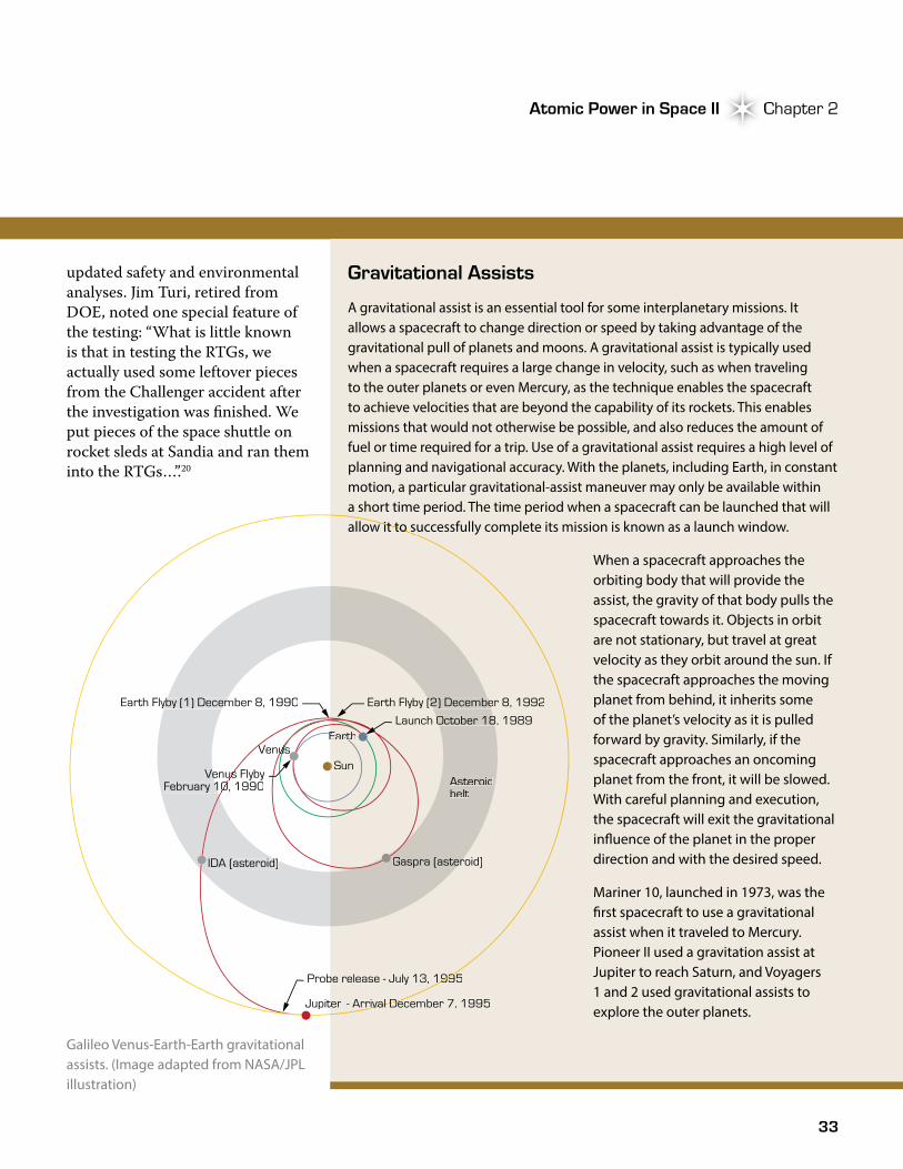
33
Atomic Power in Space II Chapter 2Atomic Power in Space II Chapter 2
updated safety and environmental analyses. Jim Turi, retired from DOE, noted one special feature of the testing: “What is little known is that in testing the RTGs, we actually used some leftover pieces from the Challenger accident after the investigation was finished. We put pieces of the space shuttle on rocket sleds at Sandia and ran them into the RTGs…”.20
Gravitational Assists
A gravitational assist is an essential tool for some interplanetary missions. It allows a spacecraft to change direction or speed by taking advantage of the gravitational pull of planets and moons. A gravitational assist is typically used when a spacecraft requires a large change in velocity, such as when traveling to the outer planets or even Mercury, as the technique enables the spacecraft to achieve velocities that are beyond the capability of its rockets. This enables missions that would not otherwise be possible, and also reduces the amount of fuel or time required for a trip. Use of a gravitational assist requires a high level of planning and navigational accuracy. With the planets, including Earth, in constant motion, a particular gravitational-assist maneuver may only be available within a short time period. The time period when a spacecraft can be launched that will allow it to successfully complete its mission is known as a launch window.
When a spacecraft approaches the orbiting body that will provide the assist, the gravity of that body pulls the spacecraft towards it. Objects in orbit are not stationary, but travel at great velocity as they orbit around the sun. If the spacecraft approaches the moving planet from behind, it inherits some of the planet’s velocity as it is pulled forward by gravity. Similarly, if the spacecraft approaches an oncoming planet from the front, it will be slowed. With careful planning and execution, the spacecraft will exit the gravitational in�uence of the planet in the proper direction and with the desired speed.
Mariner 10, launched in 1973, was the �rst spacecraft to use a gravitational assist when it traveled to Mercury. Pioneer II used a gravitation assist at Jupiter to reach Saturn, and Voyagers 1 and 2 used gravitational assists to explore the outer planets.
Sun
Gaspra (asteroid)Gaspra (asteroid)
Asteroidbelt
Probe release - July 13, 1995Probe release - July 13, 1995Probe release - July 13, 1995
allow it to successfully complete its mission is known as a launch window.
IDA (asteroid)IDA (asteroid)
- Arrival December 7, 1995- Arrival December 7, 1995JupiterJupiter
EarthEarthEarthEarthEarthEarthLaunch October 18, 1989Launch October 18, 1989
Earth Flyby (2) December 8, 1992Earth Flyby (2) December 8, 1992Earth Flyby (1) December 8, 1990Earth Flyby (1) December 8, 1990
VenusVenusVenus
Venus FlybyVenus FlybyVenus FlybyFebruary 10, 1990February 10, 1990February 10, 1990
Galileo Venus-Earth-Earth gravitational assists. (Image adapted from NASA/JPL illustration)
34
Galileo and Ulysses The General Purpose Heat Source RTGGalileo and Ulysses
By 1989, DOE and NASA had updated the safety and environmental analyses to support the planned Galileo launches. �e updated analyses reflected the use of a solid-fuel upper stage, the VEEGA, and the results from the large fragment tests, and concluded that the risks of launch with the GPHS-RTG onboard the shuttle were acceptably low. Reflecting upon the Challenger accident and its impact on the space nuclear program, Roy Zocher, one of the heat source designers from LANL, noted, “[T]hat accident…brought us to explore other possibilities in terms of accident environment, and so a good deal of the extensive safety testing originated as a result of the Challenger accident...”.21 With the new safety testing and review processes completed, Galileo and Ulysses were once again ready to fly, at least as far as DOE and NASA were concerned. Some within the public had a different opinion, however, and soon took the opportunity to make their voices heard.
In the months leading up to the Galileo launch, anti-nuclear groups like the Florida Coalition for Peace and Justice, the Foundation on Economic Trends, and the Christic Institute (a public interest law firm) began to express their opposition. Concerns were voiced over the possibility of accidents that could result in plutonium contamination of the space coast and other areas.
�e concerns culminated in protests at KSC and the filing of a first-ever lawsuit against NASA, which threatened to halt the Galileo launch. After hearing arguments from both sides of the case, the presiding judge ruled in favor of NASA. �e Galileo mission was finally a go. After the launch of Galileo, the Ulysses mission would see similar concerns and protests. Although the protests and lawsuit didn’t stop the launch, they did contribute to the establishment of pre-launch contingency planning. Such planning provides for response to radiological incidents in the unlikely event of a launch accident.1, 9, 18
The Launch and Discoveries of Galileo
After more than 10 years of development, testing, and preparations that spanned three presidential administrations, the Galileo spacecraft and its two GPHS-RTGs finally made their way to space aboard the Space Shuttle Atlantis (STS 34) when it was launched on October 18, 1989. For all involved, such launches produce an almost indescribable feeling of pride and sense of accomplishment, as described by Jim Turi: “…I can remember the first launch I was down there for, Galileo. I’m not a very emotional person but I actually had tears in my eyes when it got off the ground. It was just the excitement, the thrill,
the adrenaline, the happiness. It was just amazing. It was just totally unexpected when it occurred.”20 Galileo was successfully deployed from the shuttle, once it reached orbit, and sent safely on its way to Jupiter via the gravity assists.
During the flyby of Earth in December 1990, Galileo provided the first photographs taken by an unmanned spacecraft of the Earth and moon together and confirmed the existence of a huge ancient impact basin in the southern part of the far side of the moon that had never been mapped. �e first multispectral study of the moon showed evidence of more extensive lunar volcanism than previously thought.22 On its six-year outbound journey to Jupiter, the spacecraft provided the first close-up observations of asteroids (Gaspra and Ida) and also recorded the collision of the Shoemaker–Levy comet with Jupiter.
A probe was released from the orbiter on July 13, 1995. Once released, it could no longer be commanded and followed its predetermined path for 147 days before entering the Jovian atmosphere. After the probe was released, the orbiter trajectory was altered to fly over the site where the probe encountered the planet so it could relay data from the probe back to Earth. �e orbiter began circling Jupiter on December 7, 1995, becoming the first spacecraft to orbit
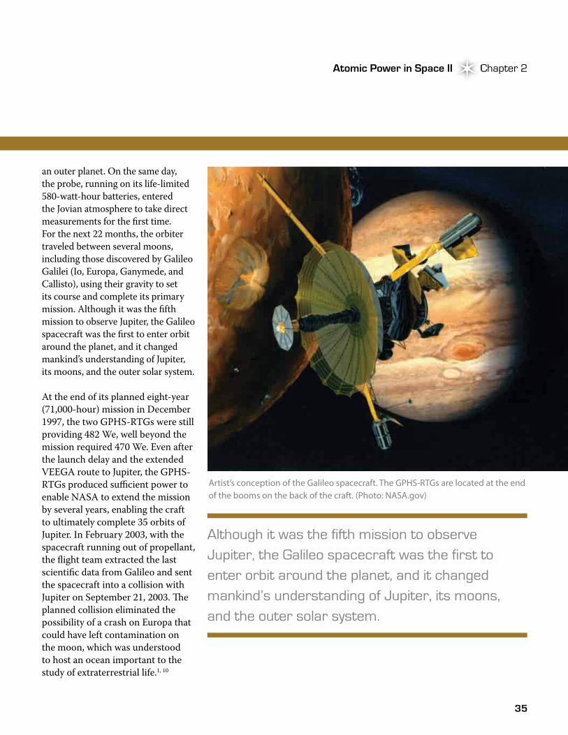
Atomic Power in Space II Chapter 2Atomic Power in Space II Chapter 2
an outer planet. On the same day, the probe, running on its life-limited 580-watt-hour batteries, entered the Jovian atmosphere to take direct measurements for the first time. For the next 22 months, the orbiter traveled between several moons, including those discovered by Galileo Galilei (Io, Europa, Ganymede, and Callisto), using their gravity to set its course and complete its primary mission. Although it was the fifth mission to observe Jupiter, the Galileo spacecraft was the first to enter orbit around the planet, and it changed mankind’s understanding of Jupiter, its moons, and the outer solar system.
At the end of its planned eight-year (71,000-hour) mission in December 1997, the two GPHS-RTGs were still providing 482 We, well beyond the mission required 470 We. Even after the launch delay and the extended VEEGA route to Jupiter, the GPHS-RTGs produced sufficient power to enable NASA to extend the mission by several years, enabling the craft to ultimately complete 35 orbits of Jupiter. In February 2003, with the spacecraft running out of propellant, the flight team extracted the last scientific data from Galileo and sent the spacecraft into a collision with Jupiter on September 21, 2003. �e planned collision eliminated the possibility of a crash on Europa that could have left contamination on the moon, which was understood to host an ocean important to the study of extraterrestrial life.1, 10
35
Artist’s conception of the Galileo spacecraft. The GPHS-RTGs are located at the end of the booms on the back of the craft. (Photo: NASA.gov)
Although it was the fifth mission to observe Jupiter, the Galileo spacecraft was the first to enter orbit around the planet, and it changed mankind’s understanding of Jupiter, its moons, and the outer solar system.
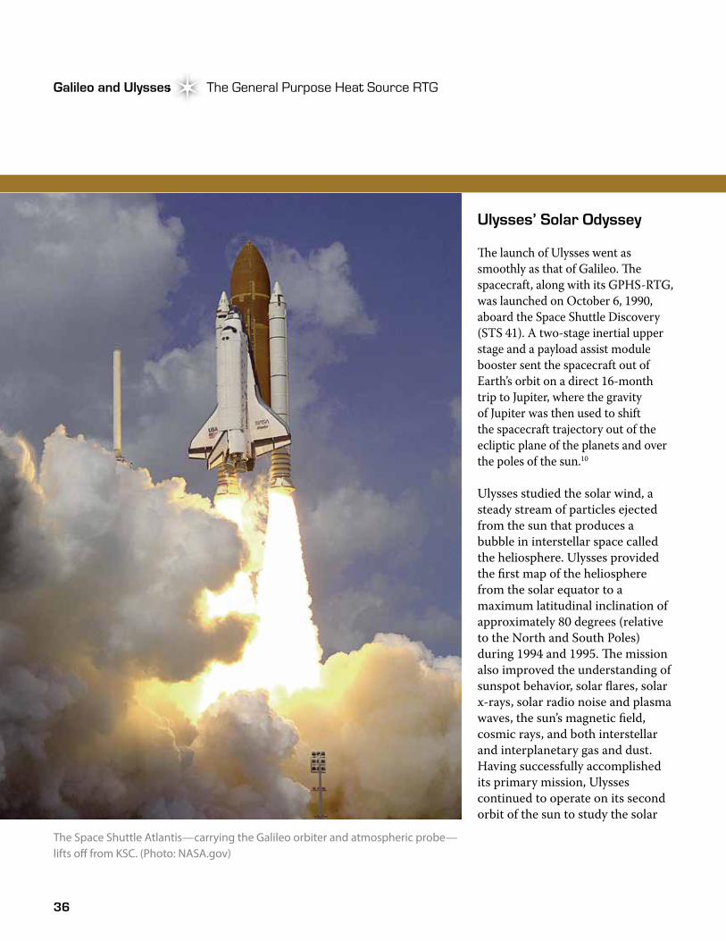
36
Galileo and Ulysses The General Purpose Heat Source RTGGalileo and Ulysses
Ulysses’ Solar Odyssey
�e launch of Ulysses went as smoothly as that of Galileo. �e spacecraft, along with its GPHS-RTG, was launched on October 6, 1990, aboard the Space Shuttle Discovery (STS 41). A two-stage inertial upper stage and a payload assist module booster sent the spacecraft out of Earth’s orbit on a direct 16-month trip to Jupiter, where the gravity of Jupiter was then used to shift the spacecraft trajectory out of the ecliptic plane of the planets and over the poles of the sun.10
Ulysses studied the solar wind, a steady stream of particles ejected from the sun that produces a bubble in interstellar space called the heliosphere. Ulysses provided the first map of the heliosphere from the solar equator to a maximum latitudinal inclination of approximately 80 degrees (relative to the North and South Poles) during 1994 and 1995. �e mission also improved the understanding of sunspot behavior, solar flares, solar x-rays, solar radio noise and plasma waves, the sun’s magnetic field, cosmic rays, and both interstellar and interplanetary gas and dust. Having successfully accomplished its primary mission, Ulysses continued to operate on its second orbit of the sun to study the solar
The Space Shuttle Atlantis—carrying the Galileo orbiter and atmospheric probe—lifts o� from KSC. (Photo: NASA.gov)
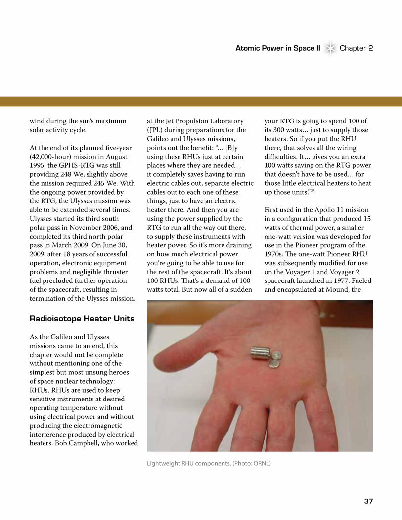
37
Atomic Power in Space II Chapter 2Atomic Power in Space II Chapter 2
wind during the sun’s maximum solar activity cycle.
At the end of its planned five-year (42,000-hour) mission in August 1995, the GPHS-RTG was still providing 248 We, slightly above the mission required 245 We. With the ongoing power provided by the RTG, the Ulysses mission was able to be extended several times. Ulysses started its third south polar pass in November 2006, and completed its third north polar pass in March 2009. On June 30, 2009, after 18 years of successful operation, electronic equipment problems and negligible thruster fuel precluded further operation of the spacecraft, resulting in termination of the Ulysses mission.
Radioisotope Heater Units
As the Galileo and Ulysses missions came to an end, this chapter would not be complete without mentioning one of the simplest but most unsung heroes of space nuclear technology: RHUs. RHUs are used to keep sensitive instruments at desired operating temperature without using electrical power and without producing the electromagnetic interference produced by electrical heaters. Bob Campbell, who worked
at the Jet Propulsion Laboratory (JPL) during preparations for the Galileo and Ulysses missions, points out the benefit: “… [B]y using these RHUs just at certain places where they are needed… it completely saves having to run electric cables out, separate electric cables out to each one of these things, just to have an electric heater there. And then you are using the power supplied by the RTG to run all the way out there, to supply these instruments with heater power. So it’s more draining on how much electrical power you’re going to be able to use for the rest of the spacecraft. It’s about 100 RHUs. �at’s a demand of 100 watts total. But now all of a sudden
your RTG is going to spend 100 of its 300 watts… just to supply those heaters. So if you put the RHU there, that solves all the wiring difficulties. It… gives you an extra 100 watts saving on the RTG power that doesn’t have to be used… for those little electrical heaters to heat up those units.”23
First used in the Apollo 11 mission in a configuration that produced 15 watts of thermal power, a smaller one-watt version was developed for use in the Pioneer program of the 1970s. �e one-watt Pioneer RHU was subsequently modified for use on the Voyager 1 and Voyager 2 spacecraft launched in 1977. Fueled and encapsulated at Mound, the
Lightweight RHU components. (Photo: ORNL)
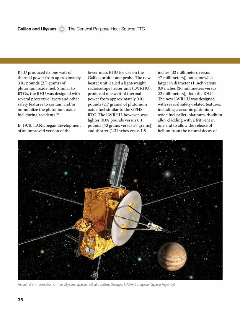
38
Galileo and Ulysses The General Purpose Heat Source RTGGalileo and Ulysses
RHU produced its one watt of thermal power from approximately 0.01 pounds (2.7 grams) of plutonium oxide fuel. Similar to RTGs, the RHU was designed with several protective layers and other safety features to contain and/or immobilize the plutonium oxide fuel during accidents.24
In 1978, LANL began development of an improved version of the
lower mass RHU for use on the Galileo orbiter and probe. �e new heater unit, called a light-weight radioisotope heater unit (LWRHU), produced one watt of thermal power from approximately 0.01 pounds (2.7 grams) of plutonium oxide fuel similar to the GPHS-RTG. �e LWRHU, however, was lighter (0.08 pounds versus 0.1 pounds [40 grams versus 57 grams]) and shorter (1.3 inches vesus 1.8
inches [32 millimeters versus 47 millimeters]) but somewhat larger in diameter (1 inch versus 0.9 inches [26 millimeters versus 22 millimeters]) than the RHU. �e new LWRHU was designed with several safety-related features, including a ceramic plutonium oxide fuel pellet; platinum-rhodium alloy cladding with a frit vent in one end to allow the release of helium from the natural decay of
An artist’s impression of the Ulysses spacecraft at Jupiter. (Image: NASA/European Space Agency)
39
Atomic Power in Space II Chapter 2Atomic Power in Space II Chapter 2
the plutonium (whereas the RHU was designed to contain helium); a pyrolytic graphite thermal insulator to keep the clad from melting in case of re-entry; and a FWPF aeroshell for re-entry protection (an improved material relative to that used in the RHU). Completely assembled, the LWRHU was a cylinder approximately 1.25 inches (3 centimeters) long and one inch (2.5 centimeters) in diameter,
“ When you look at the photos from the Galileo and Ulysses missions, people marvel at the pictures and the science… And you realize, you know, that couldn’t have happened if it wasn’t for these RTGs, and usually the RTGs aren’t even mentioned….But those who are in the community, we know, and… there’s just an awful lot of pride… when you think about how you played a small part in these missions’ successes and advancing science...that you helped make these missions successful, and I think that’s why I and others just have a warm place in our heart for these programs. Let’s face it, space exploration is still sexy and it will be for a long time, I think.” –Jim Turi, DOE
similar in size to a modern-day C-cell battery.25
�e LWRHU development effort originally planned for design, testing, production, and delivery to be completed in 14 months; however, the postponement of the Galileo launch enabled development of a design with an increased safety margin and allowed for additional testing. �e fuel containment
capability of the new lightweight heater unit was evaluated in safety tests similar to those for the GPHS-RTG. �e tests included overpressures, impact by aluminum alloy bullets, extended exposure to burning solid-fuel propellant, impact on a hard surface in various orientations at velocities greater than terminal, and immersion for nearly two years at a pressure equivalent to 6,000 meters of seawater.25 Following the development and testing effort, assembly of 134 LWRHUs for the Galileo mission was completed at LANL in 1985; however, only 120 of the units were used on the spacecraft, with the remainder being set aside as spares.
Looking Back
�e success of the GPHS-RTG and LWRHU on the Galileo and Ulysses spacecraft closed another chapter in a long history of the quiet technology. �e GPHS-RTGs extended mission life and provided the power necessary to transmit countless pictures, data, and other information that enhanced the understanding of our solar system. �e LWRHUs provided heat that kept scientific instruments and other electronics warm (and functioning) in the coldness of deep space. And in both cases, with the GPHS-RTG and LWRHU, DOE had developed units that would power and heat NASA missions for decades to come.