Embed Size (px)
Citation preview

Thermal Analysis and Design of Cooling Towers
P M V SubbaraoProfessor
Mechanical Engineering Department
I I T Delhi
Pay material for Electric Power….

Natural Draught Cooling Tower
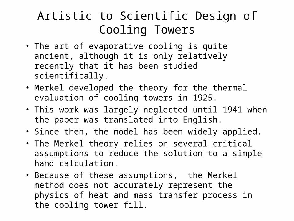
Artistic to Scientific Design of Cooling Towers
• The art of evaporative cooling is quite ancient, although it is only relatively recently that it has been studied scientifically.
• Merkel developed the theory for the thermal evaluation of cooling towers in 1925.
• This work was largely neglected until 1941 when the paper was translated into English.
• Since then, the model has been widely applied.
• The Merkel theory relies on several critical assumptions to reduce the solution to a simple hand calculation.
• Because of these assumptions, the Merkel method does not accurately represent the physics of heat and mass transfer process in the cooling tower fill.
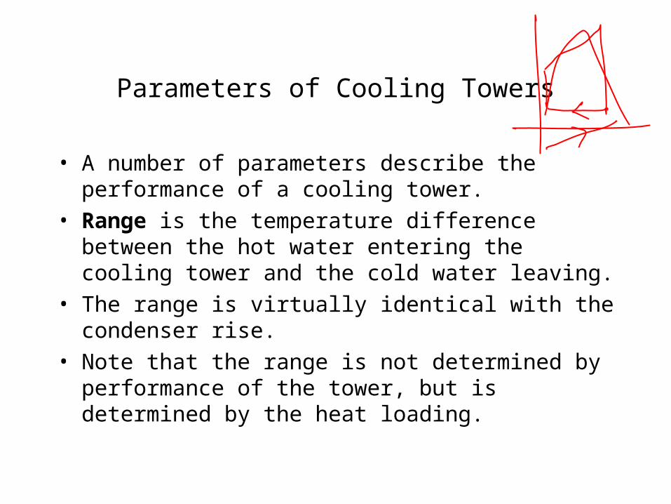
Parameters of Cooling Towers
• A number of parameters describe the performance of a cooling tower.
• Range is the temperature difference between the hot water entering the cooling tower and the cold water leaving.
• The range is virtually identical with the condenser rise.
• Note that the range is not determined by performance of the tower, but is determined by the heat loading.
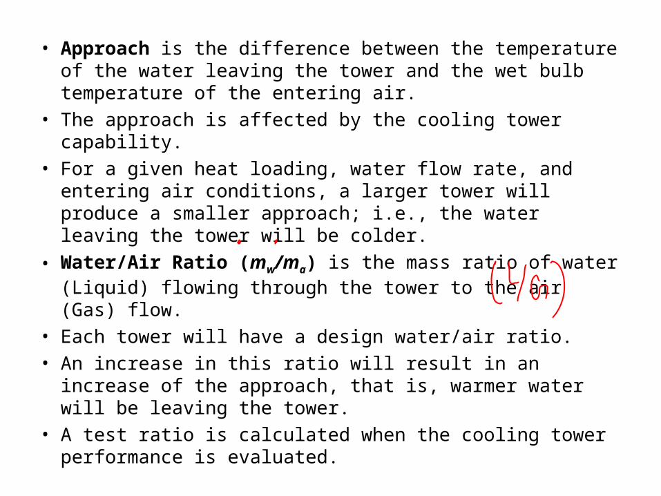
• Approach is the difference between the temperature of the water leaving the tower and the wet bulb temperature of the entering air.
• The approach is affected by the cooling tower capability.
• For a given heat loading, water flow rate, and entering air conditions, a larger tower will produce a smaller approach; i.e., the water leaving the tower will be colder.
• Water/Air Ratio (mw/ma) is the mass ratio of water (Liquid) flowing through the tower to the air (Gas) flow.
• Each tower will have a design water/air ratio.
• An increase in this ratio will result in an increase of the approach, that is, warmer water will be leaving the tower.
• A test ratio is calculated when the cooling tower performance is evaluated.
a
v
m
m
AirDry of Flow Mass
Vapour Water of Flow Mass
a
ua
aaa M
TRmTRmVp
v
uv
vvv M
TRmTRmVp
a
v
a
v
a
v
u
aa
u
vv
p
p
p
p
M
M
TRVpM
TRVpM
622.0
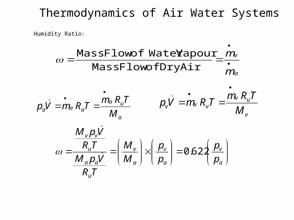
Thermodynamics of Air Water Systems
Humidity Ratio:
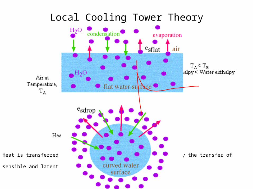
Local Cooling Tower Theory
Heat is transferred from water drops to the surrounding air by the transfer of sensible and latent heat

Global Conservation Laws for Evaporative Cooling
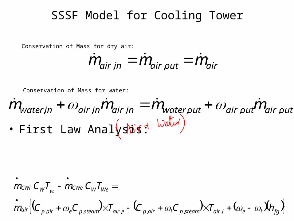
SSSF Model for Cooling Tower
Conservation of Mass for dry air:
airoutairinair mmm ,,
outairoutairoutwaterinairinairinwater mmmm ,,,,,, Conservation of Mass for water:
• First Law Analysis:
fgieiairsteampiairpeairsteampeairpair
WeWCWeWCWi
hTCCTCCm
TCmTCmWi
,,,,,,

Enthalpy of Wet air
fgiiairsteampiairpfgeeairsteampeairpair
WeWCWeWCWi
hTCChTCCm
TCmTCmWi
,,,,,,
fgiairsteampiairpfgeairsteampeairpair
WeWCWeWCWi
hTCChTCCm
TCmTCmWi
,,,,,,
iimoistureiairiwetaireemoistureeairewetairair
WeWCWeWCWi
pTfhpTfhm
TCmTCmWi
,,(,,( ,,,,,,

Local Heat and Mass Transfer in water air system
dzdz
dTT
dzdz
dmm
ww
ww
w
w
T
m
dzdz
dhh
dzdz
dm
aa
a
1
a
a
h
m 1
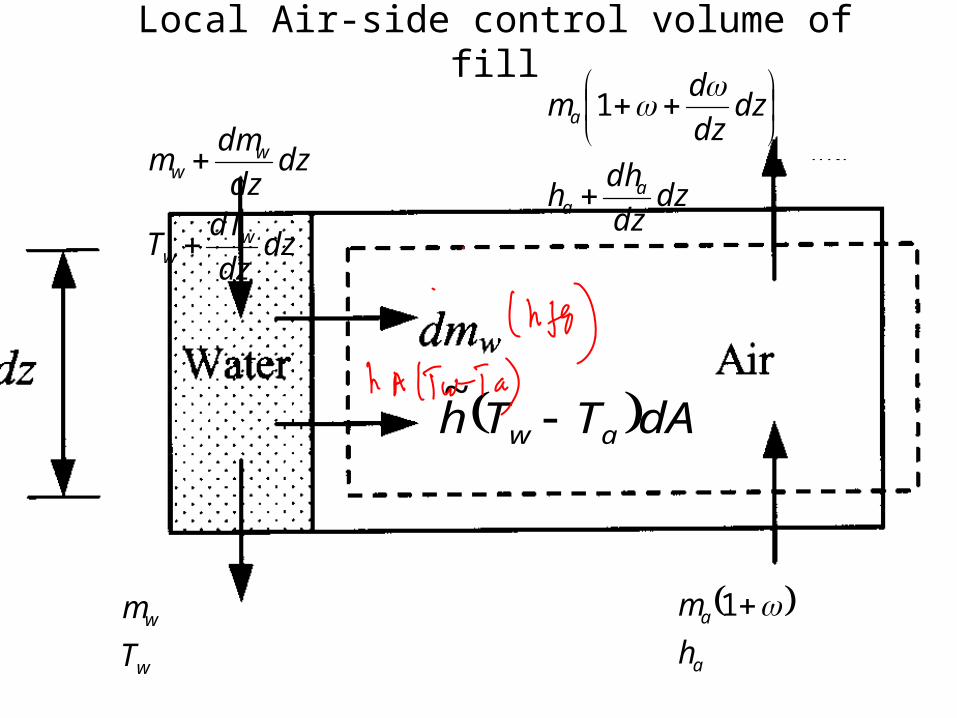
Local Air-side control volume of fill
dATTh aw ~
dzdz
dTT
dzdz
dmm
ww
ww
w
w
T
m
dzdz
dhh
dzdz
dm
aa
a
1
a
a
h
m 1
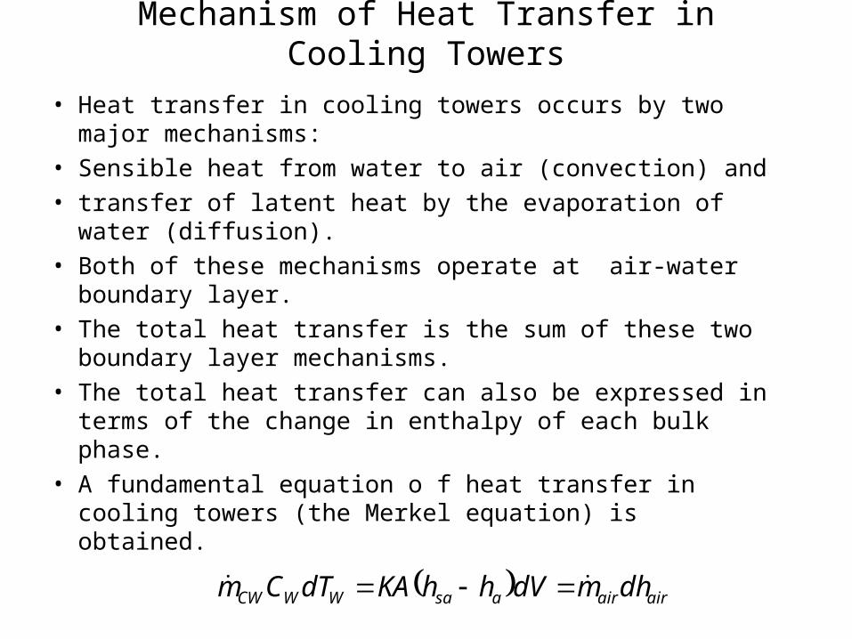
Mechanism of Heat Transfer in Cooling Towers
• Heat transfer in cooling towers occurs by two major mechanisms:
• Sensible heat from water to air (convection) and
• transfer of latent heat by the evaporation of water (diffusion).
• Both of these mechanisms operate at air-water boundary layer.
• The total heat transfer is the sum of these two boundary layer mechanisms.
• The total heat transfer can also be expressed in terms of the change in enthalpy of each bulk phase.
• A fundamental equation o f heat transfer in cooling towers (the Merkel equation) is obtained.
airairasaWWCW dhmdVhhKAdTCm

The Merkel Method
• The Merkel method, developed in the 1920s, relies on several critical assumptions to reduce the solution to a simple manual iteration.
• These assumptions are:
• The resistance for heat transfer in the water film is negligible,
• The effect of water loss by evaporation on energy balance or air process state is neglected,
• The specific heat of air-stream mixture at constant pressure is same as that of the dry air, and
• The ratio of hconv/hdiff (Lewis factor) for humid air is unity.
• Merkel combined equations for heat and water vapor transfer into a single equation similar as
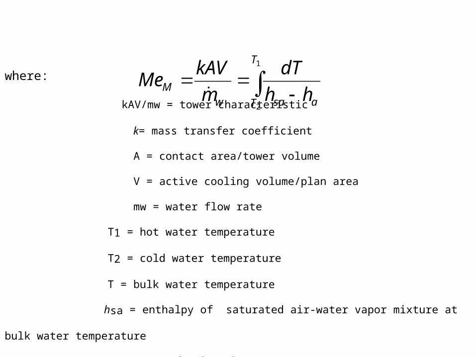
where:
kAV/mw = tower characteristic
k= mass transfer coefficient
A = contact area/tower volume
V = active cooling volume/plan area
mw = water flow rate
T1 = hot water temperature
T2 = cold water temperature
T = bulk water temperature
hsa = enthalpy of saturated air-water vapor mixture at bulk water temperature
(J/kg dry air)
ha = enthalpy of air-water vapor mixture (J/kg dry air )
1
2
T
T asawM hh
dT
m
kAVMe
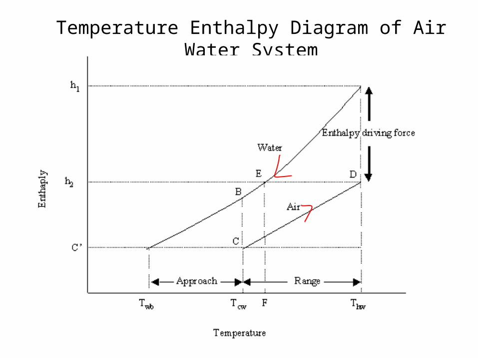
Temperature Enthalpy Diagram of Air Water System

Tower Characteristics
• Tower Characteristic (MeM or NTU) is a characteristic of
the tower that relates tower design and operating characteristics to the amount of heat that can be transferred.
• For a given set of operating conditions, the design constants that depend on the tower fill.
• For a tower that is to be evaluated using the characteristic curve method, the manufacturer will provide a tower characteristic curve.
n
a
w
m
mCNTU

Charts for Merkel Number
MMe
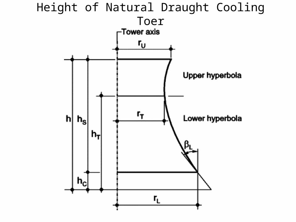
Height of Natural Draught Cooling Toer
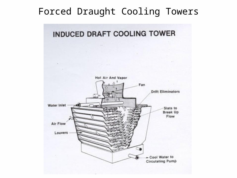
Forced Draught Cooling Towers
SUPPLY TOWER CHARACTERISTIC
• The supply tower characteristic of the cooling tower can be evaluated with the help of cooling tower fill characteristics curves provided by manufacturer which takes into account the effect of rain and spray zones as well as fill fouling.
• These curves are certified by the cooling tower institute.
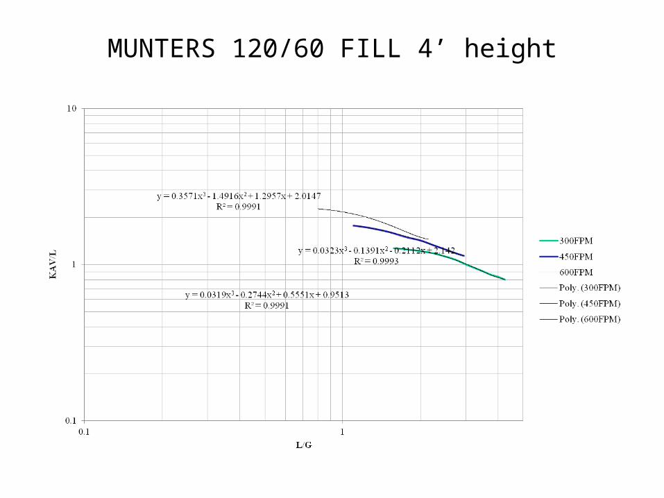
MUNTERS 120/60 FILL 4’ height

MUNTERS 120/60 FILL 3’ Height

Generalized Equation for Cooling Tower Supply
• A generalized equation for cooling tower supply can be developed from the manufacturer curves (known as the supply equation) and is of the form:
m
a
wnair m
muC
L
KAV

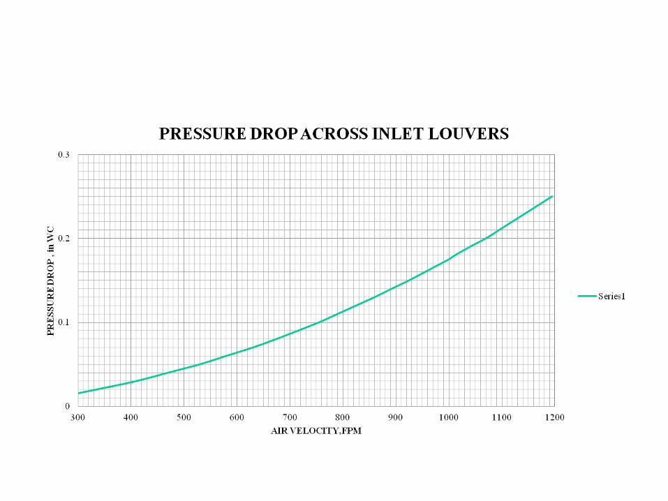
Air Side Pressure Drop
• Manufacturer pressure drop curves are available for pressure drops at the inlet louvers, drift eliminators and the fill packing.
• These curves are shown in the following slides.• Using curve fitting software, generalized pressure
drop equations are found developed so as to calculate the pressure drops.

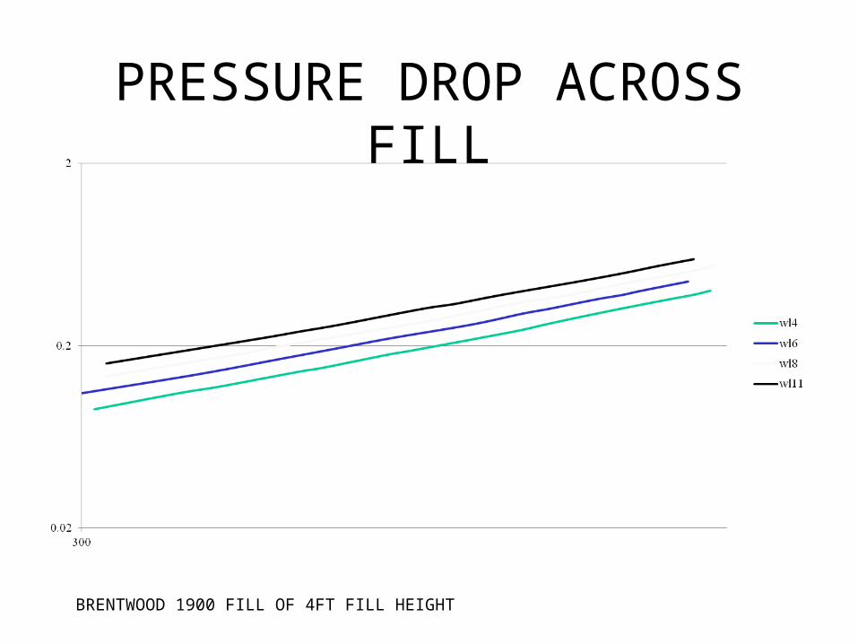
PRESSURE DROP ACROSS FILL
BRENTWOOD 1900 FILL OF 4FT FILL HEIGHT
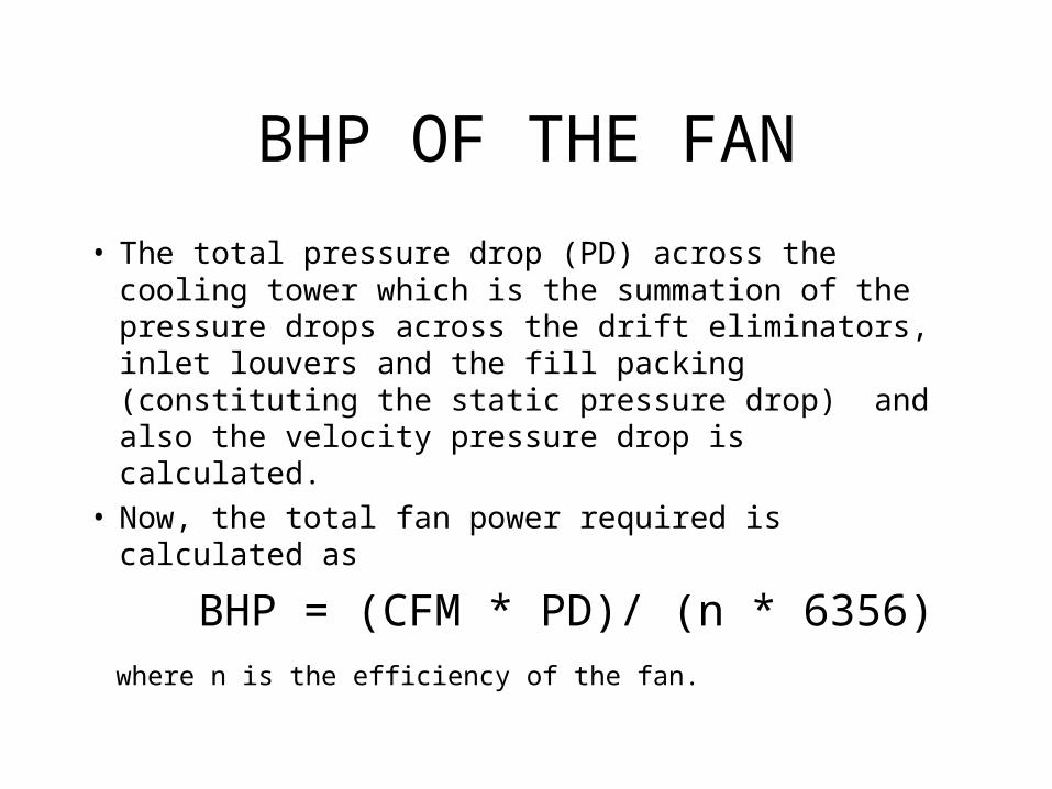
BHP OF THE FAN
• The total pressure drop (PD) across the cooling tower which is the summation of the pressure drops across the drift eliminators, inlet louvers and the fill packing (constituting the static pressure drop) and also the velocity pressure drop is calculated.
• Now, the total fan power required is calculated as
BHP = (CFM * PD)/ (n * 6356) where n is the efficiency of the fan.
ANOTHER METHOD
• We can also map the demand curve foe varying KAV/L values with varying L/G on the manufacturers curves for tower characteristics in order to find the L/G ratio of the cooling tower.
• After obtaining the L/G ratio all the steps to be followed are same as the previous method.

Loss of Water
• Evaporation Rate is the fraction of the circulating water that is evaporated in the cooling process.
• A typical design evaporation rate is about 1% for every 12.5C range at typical design conditions.
• It will vary with the season, since in colder weather there is more sensible heat transfer from the water to the air, and therefore less evaporation.
• The evaporation rate has a direct impact on the cooling tower makeup water requirements.
• Drift is water that is carried away from the tower in the form of droplets with the air discharged from the tower.
• Most towers are equipped with drift eliminators to minimize the amount of drift to a small fraction of a percent of the water circulation rate.
• Drift has a direct impact on the cooling tower makeup water requirements.
• Recirculation is warm, moist air discharged from the tower that mixes with the incoming air and re-enters the tower.
• This increases the wet bulb temperature of the entering air and reduces the cooling capability of the tower.
• During cold weather operation, recirculation may also lead to icing of the air intake areas.