Embed Size (px)
Citation preview
Page 2029
Thermal Analysis of an Engine Gasket At
Different Operating Temperatures
V.Arjun
M.Tech Student
Kakinada Institute of Technology
& Science,
Divili, Andhra Pradesh, India
Mr. V.V. Ramakrishna,
Associate professor,
Kakinada Institute of Technology
& Science,
Divili, Andhra Pradesh, India.
Mr. S. Rajasekhar,
Associate professor,
Kakinada Institute of Technology
& Science,
Divili, Andhra Pradesh, India.
Abstract:
Gasket sits between the engine block and cylinder
head in an engine. Its purpose is to seal the cylinders
to ensure maximum compression and avoid leakage
of coolant or engine oil into the cylinders. From our
project, we would like to modify the material and
design of the gasket of four cylinder engine. MLS or
Multiple Layers Steel (These typically consist of three
layers of steel) and asbestos – Most modern head
engines are produced with MLS gaskets. The contact
faces are usually coated with a rubber-like coating
such as Viton that adheres to the cylinder block and
cylinder head while the thicker center layer is left
bare. Because of the health risk of fine asbestos
fibers, gasket manufacturers are forced to look for
alternatives to asbestos. Various possibilities of
substituting asbestos in cylinder head gaskets are
characterized by different problems of development.
Elastomer-bonded soft materials, i.e. combinations of
Kevlar fibers, carbon fiber, pyrosic ceramic glass
fiber materials can be used in cylinder head gaskets
to replace soft-material layers containing asbestos.
Because of its numerous specific sealing properties,
another alternative to replace gasket layers
containing carbon, Kevlar, pyrosic ceramic glass
fiber which has been chemically and thermally
treated. The comparison of result of these three
materials is used to choose the better one using
ANSYS 14.5.
In this project various optimization methods are
implemented by varying the material of gasket. The
modeling of gasket is done by using Pro-E design
software. Finite Element analysis using ANSYS has
been done to increase the thermal and structural
properties gasket material.
I.INTRODUCTION
A Cylinder Gasket or head gasket is a gasket that sits
between the engine block and cylinder head(s) in an
internal combustion engine.
Its purpose is to seal the cylinders to ensure maximum
compression and avoid leakage of coolant or engine oil
into the cylinders; as such, it is the most critical sealing
application in any engine and, as part of the
combustion chamber, it shares the same strength
requirements as other combustion chamber
components.
The condition of a head gasket is typically investigated
by checking the compression pressure with a pressure
gauge, or better, a leak-down test, and/or noting any
indication of combustion gases in the cooling system
on a water-cooled engine. Oil mixed with coolant and
excessive coolant loss with no apparent cause, or
presence of carbon monoxide or hydrocarbon gases in
the expansion tank of the cooling system can also be
signs of head gasket problems. A good sign of head
gasket failure on water-cooled engines is the presence
of a substance that resembles mayonnaise in the oil,
often to be seen on the dipstick, or oil filler cap.
However, the presence of this substance is not
conclusive proof of head gasket failure, since oil could
mix with the coolant via other routes.
A leaking head gasket can be classified as either

Page 2030
external or internal. An external leak can be identified
as oil and coolant accumulating underneath the engine.
The presence of coolant can be detected by shining a
black light on what appears to be an oil leak; the
appearance of coolant will show up under the black
light. External leaks can also appear as previously
described in the oil. An internal leak can usually be
diagnosed by excessive coolant accumulating in the
expansion tank along with the presence of
hydrocarbons in the form of foam. The possibility of
vapors or condensation and/or water (from the road or
rain) building up (in aftermarket product installation)
from an external breather or catch tank from the head
(rocker cover) can also cause a buildup of froth or
foam in the oil but is highly unlikely
3D DESIGN OF THE MODEL
THERMAL ANALYSIS OF CYLINDER GASKET
WITH AL 7475 AT 142OC
IMPORT MODEL
MESH MODEL
INPUT DATA
TEMPERATURE
TOTAL HEAT FLUX
DIRECTIONAL HEAT FLUX
Page 2031
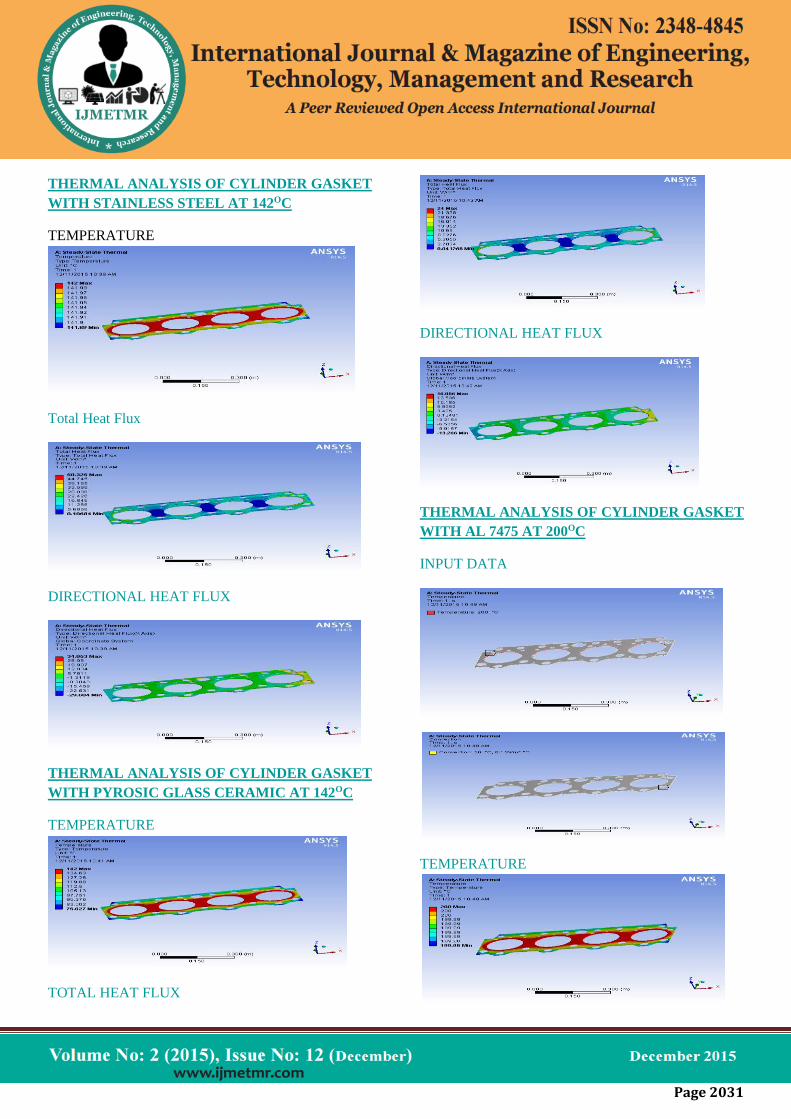
THERMAL ANALYSIS OF CYLINDER GASKET
WITH STAINLESS STEEL AT 142OC
TEMPERATURE
Total Heat Flux
DIRECTIONAL HEAT FLUX
THERMAL ANALYSIS OF CYLINDER GASKET
WITH PYROSIC GLASS CERAMIC AT 142OC
TEMPERATURE
TOTAL HEAT FLUX
DIRECTIONAL HEAT FLUX
THERMAL ANALYSIS OF CYLINDER GASKET
WITH AL 7475 AT 200OC
INPUT DATA
TEMPERATURE

Page 2032
TOTAL HEAT FLUX
DIRECTIONAL HEAT FLUX
THERMAL ANALYSIS OF CYLINDER GASKET
WITH STAINLESS STEEL AT 200OC
TEMPERATURE
TOTAL HEAT FLUX
DIRECTIONAL HEAT FLUX
THERMAL ANALYSIS OF CYLINDER GASKET
WITH PYROSIC GLASS CERAMIC AT 200OC
TEMPERATURE
TOTAL HEAT FLUX
DIRECTIONAL HEAT FLUX
THERMAL ANALYSIS OF CYLINDER GASKET
WITH AL 7475 AT 280OC
INPUT DATA

Page 2033
TEMPERATURE
TOTAL HEAT FLUX
DIRECTIONAL HEAT FLUX
THERMAL ANALYSIS OF CYLINDER GASKET
WITH STAINLESS STEEL AT 280OC
TEMPERATURE
TOTAL HEAT FLUX
DIRECTIONAL HEAT FLUX
THERMAL ANALYSIS OF CYLINDER GASKET
WITH PYROSIC GLASS CERAMIC AT 280OC
TEMPERATURE
TOTAL HEAT FLUX

Page 2034
DIRECTIONAL HEAT FLUX
THERMAL ANALYSIS OF CYLINDER GASKET
WITH AL 7475 AT 360OC
INPUT DATA
TEMPERATURE
TOTAL HEAT FLUX
DIRECTIONAL HEAT FLUX
THERMAL ANALYSIS OF CYLINDER GASKET
WITH STAINLESS STEEL AT 360OC
TEMPERATURE
TOTAL HEAT FLUX

Page 2035
DIRECTIONAL HEAT FLUX
THERMAL ANALYSIS OF CYLINDER GASKET
WITH PYROSIC GLASS CERAMIC AT 360OC
TEMPERATURE
TOTAL HEAT FLUX
DIRECTIONAL HEAT FLUX
RESULTS TABLE
THERMAL ANALYSIS OF CYLINDER GASKET
AT 142OC
THERMAL ANALYSIS OF CYLINDER GASKET
AT 200 OC
THERMAL ANALYSIS OF CYLINDER GASKET
AT 280 OC
TEMPERAT
URE
TOTAL
HEAT
FLUX
DIRECTIO
NAL HEAT
FLUX
MIN MAX MIN MA
X MIN
MA
X
AL
7475
279.
97 280
0.267
31
125.
91
-
74.0
75
85.2
06
STAIN
LESS
STEEL
279.
72 280
0.267
11
125.
81
-
74.0
09
85.1
32
PYROS
IC
GLASS
CERA
MIC
114.
07 280
0.103
17 60
-
33.1
65
42.2
14
TEMPERAT
URE
TOTAL
HEAT FLUX
DIRECTI
ONAL
HEAT
FLUX
MIN MA
X MIN
MA
X
MI
N
M
AX
AL
7475
141.
99 142
0.106
92
50.3
65
-
29.6
3
34.
082
STAIN
LESS
STEEL
141.
89 142
0.106
84
50.3
25
-
29.6
04
34.
053
PYRO
SIC
GLASS
CERA
MIC
75.6
27 142
0.041
268 24
-
13.2
06
16.
886
Page 2036
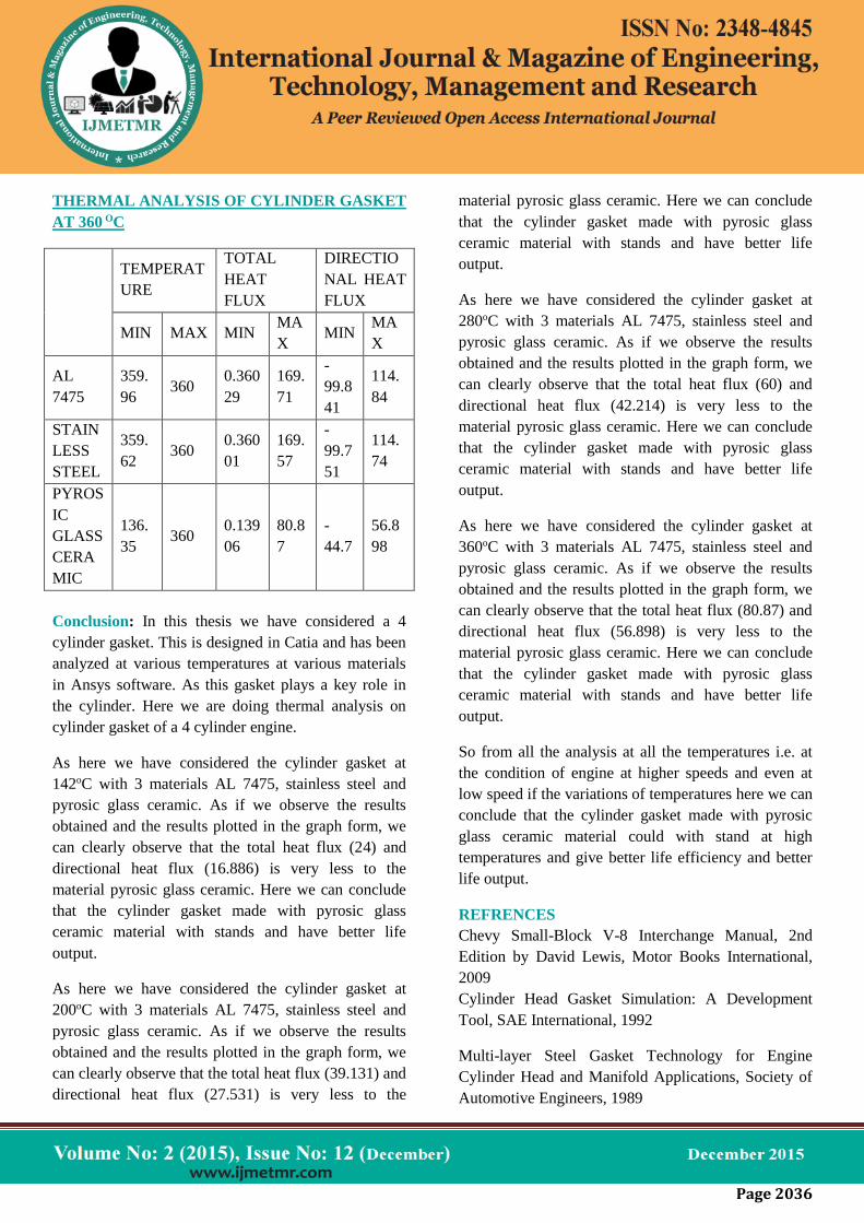
THERMAL ANALYSIS OF CYLINDER GASKET
AT 360 OC
TEMPERAT
URE
TOTAL
HEAT
FLUX
DIRECTIO
NAL HEAT
FLUX
MIN MAX MIN MA
X MIN
MA
X
AL
7475
359.
96 360
0.360
29
169.
71
-
99.8
41
114.
84
STAIN
LESS
STEEL
359.
62 360
0.360
01
169.
57
-
99.7
51
114.
74
PYROS
IC
GLASS
CERA
MIC
136.
35 360
0.139
06
80.8
7
-
44.7
56.8
98
Conclusion: In this thesis we have considered a 4
cylinder gasket. This is designed in Catia and has been
analyzed at various temperatures at various materials
in Ansys software. As this gasket plays a key role in
the cylinder. Here we are doing thermal analysis on
cylinder gasket of a 4 cylinder engine.
As here we have considered the cylinder gasket at
142oC with 3 materials AL 7475, stainless steel and
pyrosic glass ceramic. As if we observe the results
obtained and the results plotted in the graph form, we
can clearly observe that the total heat flux (24) and
directional heat flux (16.886) is very less to the
material pyrosic glass ceramic. Here we can conclude
that the cylinder gasket made with pyrosic glass
ceramic material with stands and have better life
output.
As here we have considered the cylinder gasket at
200oC with 3 materials AL 7475, stainless steel and
pyrosic glass ceramic. As if we observe the results
obtained and the results plotted in the graph form, we
can clearly observe that the total heat flux (39.131) and
directional heat flux (27.531) is very less to the
material pyrosic glass ceramic. Here we can conclude
that the cylinder gasket made with pyrosic glass
ceramic material with stands and have better life
output.
As here we have considered the cylinder gasket at
280oC with 3 materials AL 7475, stainless steel and
pyrosic glass ceramic. As if we observe the results
obtained and the results plotted in the graph form, we
can clearly observe that the total heat flux (60) and
directional heat flux (42.214) is very less to the
material pyrosic glass ceramic. Here we can conclude
that the cylinder gasket made with pyrosic glass
ceramic material with stands and have better life
output.
As here we have considered the cylinder gasket at
360oC with 3 materials AL 7475, stainless steel and
pyrosic glass ceramic. As if we observe the results
obtained and the results plotted in the graph form, we
can clearly observe that the total heat flux (80.87) and
directional heat flux (56.898) is very less to the
material pyrosic glass ceramic. Here we can conclude
that the cylinder gasket made with pyrosic glass
ceramic material with stands and have better life
output.
So from all the analysis at all the temperatures i.e. at
the condition of engine at higher speeds and even at
low speed if the variations of temperatures here we can
conclude that the cylinder gasket made with pyrosic
glass ceramic material could with stand at high
temperatures and give better life efficiency and better
life output.
REFRENCES
Chevy Small-Block V-8 Interchange Manual, 2nd
Edition by David Lewis, Motor Books International,
2009
Cylinder Head Gasket Simulation: A Development
Tool, SAE International, 1992
Multi-layer Steel Gasket Technology for Engine
Cylinder Head and Manifold Applications, Society of
Automotive Engineers, 1989

Page 2037
1. Diesel Engine Maintenance Training Manual,
Bureau of Ships, BoD – Books on Demand,
15-Jan-2015
2. How to Build and Modify Chevrolet Small-
Block V-8 Cylinder Heads by David Vizard,
Motor Books International
3. Bickford, John H. (1997). Gaskets and
Gasketed Joints. CRC Press. p. 57. ISBN 0-
8247-9877-5.
4. Nunney, M. J. (1998). Light & Heavy Vehicle
Technology. Elsevier. p. 23. ISBN 0-7506-
3827-3.
STUDENT
V.Arjun received the B.Tech degree in mechanical
engineering, from Sarada institute of science
technology and management college of engineering,
JNTUK, Srikakulam, Andhra pradesh, India, in 2013,
and persuing m.tech in Thermal Engineering from
Kakinda Institute Of Technology And Science college
of engineering, Divili, Andhra pradesh, India.
GUIDE 1
Mr. V.V. Ramakrishna, Associate professor,
Kakinada Institute of Technology & Science, Divili,
Andhra Pradesh, India.
GUIDE 2
Mr. S. Rajasekhar,Associate professor, Kakinada
Institute of Technology & Science, Divili, Andhra
Pradesh, India.