Embed Size (px)
Citation preview
HEFAT2012
9th
International Conference on Heat Transfer, Fluid Mechanics and Thermodynamics
16 – 18 July 2012
Malta
THERMAL AND RESIDUAL STRESS ANLAYSES OF
A WELDED STAINLESS STEEL PLATE
Kaman M.O. Celik N*. and Gokce I.
*Author for correspondence
Department of Mechanitronics Engineering
Firat University,
Elazig, 23119,
Turkey ,
E-mail: [email protected]
ABSTRACT
In this study, a welding simulation was analyzed
numerically by using finite element method. Two-dimensional
model of butt welded plate was conducted in ANSYS finite
element package software. Transient thermal distribution on
ST-37 plate was obtained for all time intervals until it reaches
environment temperature. The initial temperature of ST-37 was
considered 300 K, whilst the temperature of welded zone was
assumed to be 1773 K. The enthalpy and density of the welded
zone material were assumed to have temperature dependent
values, although the non-welded zone of the steel was
considered to have constant values. In accordance to this,
plastic stresses were presented base on the elasto-plastic
bilinear material behavior using structural analysis. Finally,
residual stresses were found out by removing loads on the butt
welded plate. Changing of residual stresses and spread of
plastic zones according to cooling time were investigated.
INTRODUCTION
Nowadays, there is wide application area of metallurgical
joints made by welding in fabrication industry due to their
advanced properties such as high joint efficiency, water and air
tightness and low manufacturing cost. The types of welded
joint can be classified into five basic categories; butt, fillet,
corners, lap and edge [1]. Butt welds are commonly used in
joining metal plates either to same metal or to different metal.
Problem associated with welded joints is residual stress near the
weld zone on the metal plate due to localized heating by the
welding process. If residual stresses reach high values, this
situation causes a reduction of load capacity and complex
failure modes. Because of this reason, it is wanted more
detailed design knowledge and production techniques about
welded joints. For the prediction of the temperature and
residual stress distribution, numerical studies on thermo-
mechanical behaviour of welded structures have increased with
the development of finite element method in addition to the
experimental studies [2-4].
Teng et al. [1] described the thermal elasto-plastic analysis
using finite element techniques to analyze the
thermomechanical behavior and evaluate the residual stresses
and angular distortions of the T-joints in fillet welds. The
effects of flange thickness, welding penetration depth and
restraint condition of welding on the residual stresses and
distortions were discussed.
Barsoum and Lundback [5] carried out two and three
dimensional finite element welding simulations in order to
study the formation of the residual stresses due to 3D effect of
the welding process. Residual stress measurements were carried
out using X-ray diffraction technique on the manufactured T-
welded structure. The 2D residual stress predictions showed
good agreement with measurements.
Barsoum and Barsoum [6] developed a welding simulation
procedure using the finite element software ANSYS in order to
predict residual stresses. The procedure was verified with
temperature and residual stress measurements found in the
literature on multi-pass butt welded plates and T-fillet welds.
The predictions showed qualitative good agreement with
experiments. The welding simulation procedure was then
employed on a welded ship engine frame box at MAN B&W. A
subroutine for LEFM analysis was developed in 2D in order to
predict the crack path of propagating fatigue cracks.
Teng et al. [7] analyzed the thermo-mechanical behaviour
and evaluated the residual stresses with various types of
welding sequence in single-pass, multi-pass butt-welded plates
and circular patch welds. This was achieved by performing
thermal elasto-plastic analysis using finite element techniques.
Lindgren [8-10] used finite element simulation in order to
predict temperature fields, residual stresses and deformation
due to welding in 2D and 3D.
Kong et al. [11] developed a model based on a double-
ellipsoidal volume heat source to simulate the gas metal arc
welding (GMAW) heat input and a cylindrical volume heat
source to simulate the laser beam heat input to predict the
temperature field and thermally induced residual stress in the
hybrid laser–gas metal arc (GMA) welding process. Numerical
simulation showed that higher residual stress distributed in the
weld bead and surrounding heat-affected zone (HAZ).
Zain-ul-abdein et al [12] investigated the effect of
metallurgical phase transformations upon the residual stresses
and distortions induced by laser beam welding in a T-joint
871
configuration using the finite element method. Two separate
models were studied using different finite element codes, where
the first one describes a thermo-mechanical analysis using
ABAQUS; while the second one discusses a thermo-metallo-
mechanical analysis using SYSWELD.
Long et al. [13] investigated distortions and residual stresses
induced in butt joint of thin plates using metal inert gas
welding. A moving distributed heat source model based on
Goldak’s double-ellipsoid heat flux distribution was
implemented in finite element simulation of the welding
process.
In this study, finite element simulation of butt welded plate
is achieved using finite element software ANSYS. Initially
temperature distribution on plate is obtained according to the
initial conditions and saved for every load step. In the thermal
analysis, the initial temperature of welded ST-37 plate is
considered 300 K and the temperature of welded zone is
assumed to be 1773 K. Then structural analysis is performed
base on the elasto-plastic bilinear material behaviour using
structural analysis. At the end of the simulation, residual
stresses are obtained by removing loads on numerical model.
PROBLEM DEFINITION Residual stresses as a result of welding process for metal
plate are predicted by use of software package ANSYS. It is
assumed that electric arc welding has been applied to the ST-37
plate in a single pass in the numerical analysis. Butt welded
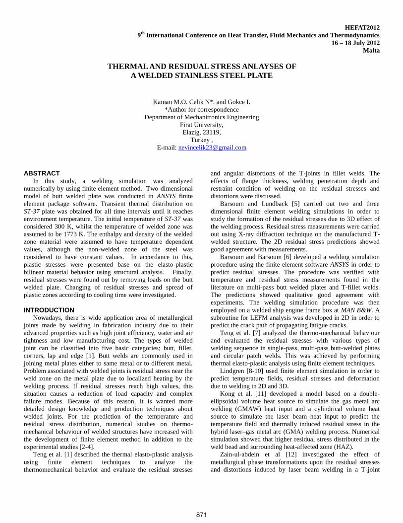
plate is modelled as 2D and its geometry and dimensions are
given Fig. 1.
Figure 1 Geometry and dimensions of welded plate
Accurate material data in the high temperature region is in
general difficult to obtain and becomes at best a reasonable
approximation. However, the material model and relevant
properties need only to represent the real material behaviour
with sufficient accuracy [6].
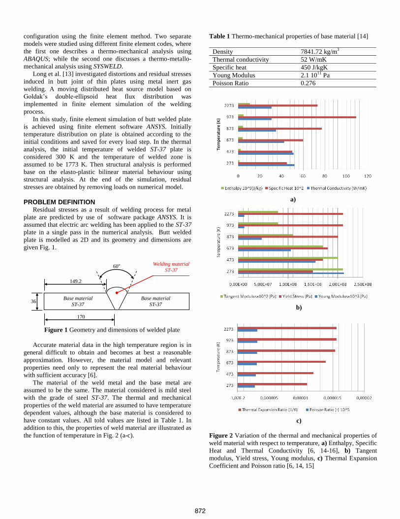
The material of the weld metal and the base metal are
assumed to be the same. The material considered is mild steel
with the grade of steel ST-37. The thermal and mechanical
properties of the weld material are assumed to have temperature
dependent values, although the base material is considered to
have constant values. All told values are listed in Table 1. In
addition to this, the properties of weld material are illustrated as
the function of temperature in Fig. 2 (a-c).
Table 1 Thermo-mechanical properties of base material [14]
Density 7841.72 kg/m3
Thermal conductivity 52 W/mK
Specific heat 450 J/kgK
Young Modulus 2.1 1011
Pa
Poisson Ratio 0.276
a)
b)
c)
Figure 2 Variation of the thermal and mechanical properties of
weld material with respect to temperature, a) Enthalpy, Specific
Heat and Thermal Conductivity [6, 14-16], b) Tangent
modulus, Yield stress, Young modulus, c) Thermal Expansion
Coefficient and Poisson ratio [6, 14, 15]
36
170
149.2
60o Welding material
ST-37
Base material
ST-37
Base material
ST-37
872
THERMAL MODEL Transient analysis is conducted in the thermal study. The
initial temperature of ST-37 is considered 300 K, whilst the
temperature of welded zone is assumed to be 1773 K. The
convective heat transfer coefficients on the surfaces are
estimated by using engineering formulae for natural convection
as 13 Wm2/K (Fig. 2a). Environment temperature is assumed as
300 K and transient analysis is continued till plate temperature
is reached. Thermal boundary conditions are exhibited in Fig. 3.
Figure 3 Boundary and initial conditions of the transient
thermal analysis model
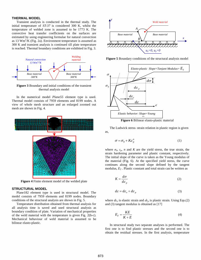
In the numerical model Plane55 element type is used.
Thermal model consists of 7959 elements and 8199 nodes. A
view of whole mesh structure and an enlarged zoomed out
mesh are shown in Fig. 4.
Figure 4 Finite element model of the welded plate
STRUCTURAL MODEL
Plane182 element type is used in structural model. The
model consists of 7959 elements and 8199 nodes. Boundary
conditions of the structural analysis are shown in Fig. 5.
Temperature distribution obtained from thermal analysis for
all analysis time is saved and used structural analysis as
boundary condition of plate. Variation of mechanical properties
of the weld material with the temperature is given Fig. 2(b-c).
Mechanical behaviour of weld material is assumed to be
bilinear elasto-plastic.
Figure 5 Boundary conditions of the structural analysis model
Figure 6 Bilinear elasto-plastic material
The Ludwick stress–strain relation in plastic region is given
as,
npK 0 (1)
where σ0, εp, n and K are the yield stress, the true strain, the
strain hardening parameter and plastic constant, respectively.
The initial slope of the curve is taken as the Young modulus of
the material (Fig. 6). At the specified yield stress, the curve
continues along the second slope defined by the tangent
modulus, ET . Plastic constant and total strain can be written as
pd
dK
(2)
pe ddd (3)
where dεe is elastic strain and dεp is plastic strain. Using Eqs.(2)
and (3) tangent modulus is obtained as [17]
EK
KEET
(4)
In structural study two separate analyses is performed. The
first one is to find plastic stresses and the second one is to
obtain the residual stresses. In the first analysis, temperature
Elasto-plastic Slope=Tanjant Modulus= TE
Elastic behavior: Slope=Young
Modulus = E
0
d
d
pd
ed
ux=0, uy=0
Base material
Base material
x
y
Weld material
A
B
Welding
material 1773 oK
Base material
300oK
Base material
300oK
Natural convection
13 Wm2/oK
873
distributions as thermal load obtained from thermal analysis
every time step have been applied to the plate surface and
plastic strains are calculated when the stresses exceed to the
yield stress. In the second analysis, load is removed
consecutively in order to obtain residual stress after last time
step where is obtained environment temperature on plate as
shown in Fig. 7. This figure illustrates a typical load history for
a nonlinear analysis. In the load steps 2 for Fig. 7, the Newton–
Rhapson Iteration Method is used. On the other hand, high
local displacements occurred in 2D finite element model near
the weld material. Hence, to obtain more sensitive results,
geometrically nonlinear analyses are carried out in this study.
Figure 7 Typical load history for a nonlinear analysis [17]
RESULTS AND DISCUSSIONS Temperature distribution on welded plate is given in Fig. 8
for various time steps. By checking the temperature contour
plots, it can be evidently seen that, the plate temperature
reaches to environment temperature 300 K in about 3800 s.
However, there are still small differences between temperatures
on the plate. The temperature on whole plate is equal to the 300
K when time step is 7000 s. This situation is the equilibrium
condition.
1
MNMX
X
Y
Z
300
364.333428.667
493557.333
621.667686
750.333814.667
879
FEB 8 2012
10:18:08
NODAL SOLUTION
STEP=1
SUB =1
TIME=100
TEMP (AVG)
RSYS=0
SMN =307.221
SMX =878.934
a)
1
MNMX
X
Y
Z
300
364.333428.667
493557.333
621.667686
750.333814.667
879
FEB 8 2012
10:19:36
NODAL SOLUTION
STEP=1
SUB =2
TIME=200
TEMP (AVG)
RSYS=0
SMN =326.947
SMX =623.429
b)
1
MN
MXX
Y
Z
300
364.333428.667
493557.333
621.667686
750.333814.667
879
FEB 8 2012
10:19:07
NODAL SOLUTION
STEP=1
SUB =38
TIME=3800
TEMP (AVG)
RSYS=0
SMN =324.756
SMX =330.343
c)
1
MNMX
X
Y
Z
300
364.333428.667
493557.333
621.667686
750.333814.667
879
FEB 8 2012
10:19:36
NODAL SOLUTION
STEP=1
SUB =2
TIME=200
TEMP (AVG)
RSYS=0
SMN =326.947
SMX =623.429
Figure 8 Temperature distributions on welded plate (K),
a) 100 s, b) 200 s, c) 3800 s
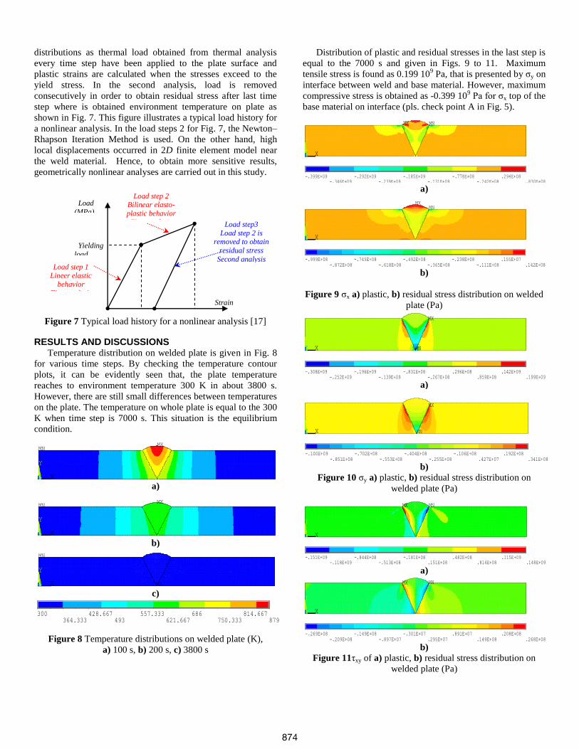
Distribution of plastic and residual stresses in the last step is
equal to the 7000 s and given in Figs. 9 to 11. Maximum
tensile stress is found as 0.199 109 Pa, that is presented by σy on
interface between weld and base material. However, maximum
compressive stress is obtained as -0.399 109 Pa for σx top of the
base material on interface (pls. check point A in Fig. 5).
1
MNMX
X
Y
Z
-.399E+09
-.346E+09-.292E+09
-.239E+09-.185E+09
-.131E+09-.778E+08
-.242E+08.294E+08
.830E+08
FEB 8 2012
13:00:34
NODAL SOLUTION
STEP=1
SUB =12
TIME=7000
SX (AVG)
RSYS=0
DMX =.255E-04
SMN =-.399E+09
SMX =.830E+08
a)
1
MNMX
X
Y
Z
-.999E+08
-.872E+08-.745E+08
-.618E+08-.492E+08
-.365E+08-.238E+08
-.111E+08.155E+07
.142E+08
FEB 8 2012
12:54:37
NODAL SOLUTION
STEP=1
SUB =1
TIME=1
SX (AVG)
RSYS=0
DMX =.928E-05
SMN =-.999E+08
SMX =.142E+08
b)
Figure 9 σx a) plastic, b) residual stress distribution on welded
plate (Pa)
1
MN
MX
X
Y
Z
-.308E+09
-.252E+09-.196E+09
-.139E+09-.831E+08
-.267E+08.296E+08
.859E+08.142E+09
.199E+09
FEB 8 2012
13:00:47
NODAL SOLUTION
STEP=1
SUB =12
TIME=7000
SY (AVG)
RSYS=0
DMX =.255E-04
SMN =-.308E+09
SMX =.199E+09
a)
1
MN
MX
X
Y
Z
-.100E+09
-.851E+08-.702E+08
-.553E+08-.404E+08
-.255E+08-.106E+08
.427E+07.192E+08
.341E+08
FEB 8 2012
12:56:02
NODAL SOLUTION
STEP=1
SUB =1
TIME=1
SY (AVG)
RSYS=0
DMX =.928E-05
SMN =-.100E+09
SMX =.341E+08
b)
Figure 10 σy a) plastic, b) residual stress distribution on
welded plate (Pa)
1
MNMX
X
Y
Z
-.151E+09
-.118E+09-.844E+08
-.513E+08-.181E+08
.151E+08.482E+08
.814E+08.115E+09
.148E+09
FEB 8 2012
13:01:18
NODAL SOLUTION
STEP=1
SUB =12
TIME=7000
SXY (AVG)
RSYS=0
DMX =.255E-04
SMN =-.151E+09
SMX =.148E+09
a)
1
MNMX
X
Y
Z
-.269E+08
-.209E+08-.149E+08
-.897E+07-.301E+07
.295E+07.891E+07
.149E+08.208E+08
.268E+08
FEB 8 2012
12:54:21
NODAL SOLUTION
STEP=1
SUB =1
TIME=1
SXY (AVG)
RSYS=0
DMX =.928E-05
SMN =-.269E+08
SMX =.268E+08
b)
Figure 11τxy of a) plastic, b) residual stress distribution on
welded plate (Pa)
Load
(MPa)
Strain
Yielding
load
Load step 1 Lineer elastic
behavior
First analysis
Load step 2 Bilinear elasto-
plastic behavior
First analysis Load step3
Load step 2 is removed to obtain
residual stress
Second analysis
874
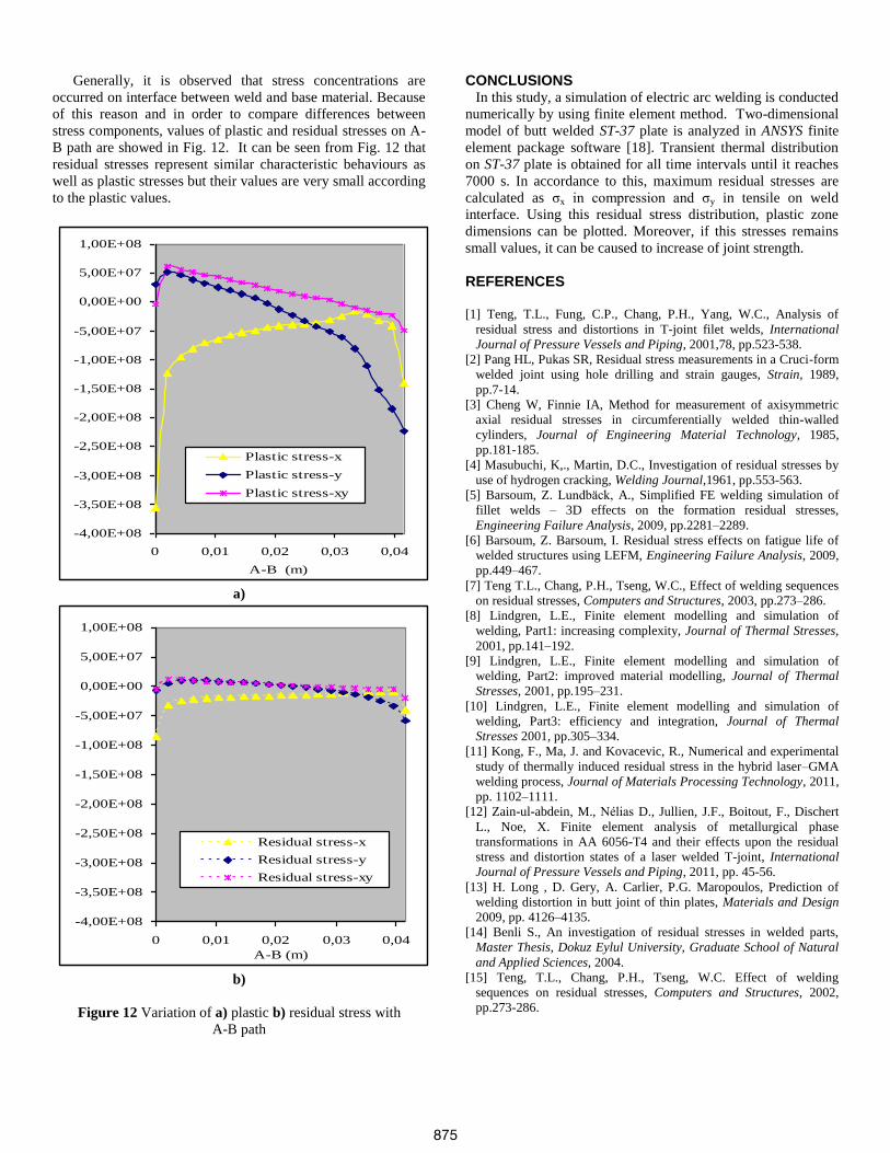
Generally, it is observed that stress concentrations are
occurred on interface between weld and base material. Because
of this reason and in order to compare differences between
stress components, values of plastic and residual stresses on A-
B path are showed in Fig. 12. It can be seen from Fig. 12 that
residual stresses represent similar characteristic behaviours as
well as plastic stresses but their values are very small according
to the plastic values.
-4,00E+08
-3,50E+08
-3,00E+08
-2,50E+08
-2,00E+08
-1,50E+08
-1,00E+08
-5,00E+07
0,00E+00
5,00E+07
1,00E+08
0 0,01 0,02 0,03 0,04
A-B (m)
Plastic stress-x
Plastic stress-y
Plastic stress-xy
a)
-4,00E+08
-3,50E+08
-3,00E+08
-2,50E+08
-2,00E+08
-1,50E+08
-1,00E+08
-5,00E+07
0,00E+00
5,00E+07
1,00E+08
0 0,01 0,02 0,03 0,04
A-B (m)
Residual stress-x
Residual stress-y
Residual stress-xy
b)
Figure 12 Variation of a) plastic b) residual stress with
A-B path
CONCLUSIONS In this study, a simulation of electric arc welding is conducted
numerically by using finite element method. Two-dimensional
model of butt welded ST-37 plate is analyzed in ANSYS finite
element package software [18]. Transient thermal distribution
on ST-37 plate is obtained for all time intervals until it reaches
7000 s. In accordance to this, maximum residual stresses are
calculated as σx in compression and σy in tensile on weld
interface. Using this residual stress distribution, plastic zone
dimensions can be plotted. Moreover, if this stresses remains
small values, it can be caused to increase of joint strength.
REFERENCES [1] Teng, T.L., Fung, C.P., Chang, P.H., Yang, W.C., Analysis of
residual stress and distortions in T-joint filet welds, International
Journal of Pressure Vessels and Piping, 2001,78, pp.523-538.
[2] Pang HL, Pukas SR, Residual stress measurements in a Cruci-form
welded joint using hole drilling and strain gauges, Strain, 1989,
pp.7-14.
[3] Cheng W, Finnie IA, Method for measurement of axisymmetric
axial residual stresses in circumferentially welded thin-walled
cylinders, Journal of Engineering Material Technology, 1985,
pp.181-185.
[4] Masubuchi, K,., Martin, D.C., Investigation of residual stresses by
use of hydrogen cracking, Welding Journal,1961, pp.553-563.
[5] Barsoum, Z. Lundbäck, A., Simplified FE welding simulation of
fillet welds – 3D effects on the formation residual stresses,
Engineering Failure Analysis, 2009, pp.2281–2289.
[6] Barsoum, Z. Barsoum, I. Residual stress effects on fatigue life of
welded structures using LEFM, Engineering Failure Analysis, 2009,
pp.449–467.
[7] Teng T.L., Chang, P.H., Tseng, W.C., Effect of welding sequences
on residual stresses, Computers and Structures, 2003, pp.273–286.
[8] Lindgren, L.E., Finite element modelling and simulation of
welding, Part1: increasing complexity, Journal of Thermal Stresses,
2001, pp.141–192.
[9] Lindgren, L.E., Finite element modelling and simulation of
welding, Part2: improved material modelling, Journal of Thermal
Stresses, 2001, pp.195–231.
[10] Lindgren, L.E., Finite element modelling and simulation of
welding, Part3: efficiency and integration, Journal of Thermal
Stresses 2001, pp.305–334.
[11] Kong, F., Ma, J. and Kovacevic, R., Numerical and experimental
study of thermally induced residual stress in the hybrid laser–GMA
welding process, Journal of Materials Processing Technology, 2011,
pp. 1102–1111.
[12] Zain-ul-abdein, M., Nélias D., Jullien, J.F., Boitout, F., Dischert
L., Noe, X. Finite element analysis of metallurgical phase
transformations in AA 6056-T4 and their effects upon the residual
stress and distortion states of a laser welded T-joint, International
Journal of Pressure Vessels and Piping, 2011, pp. 45-56.
[13] H. Long , D. Gery, A. Carlier, P.G. Maropoulos, Prediction of
welding distortion in butt joint of thin plates, Materials and Design
2009, pp. 4126–4135.
[14] Benli S., An investigation of residual stresses in welded parts,
Master Thesis, Dokuz Eylul University, Graduate School of Natural
and Applied Sciences, 2004.
[15] Teng, T.L., Chang, P.H., Tseng, W.C. Effect of welding
sequences on residual stresses, Computers and Structures, 2002,
pp.273-286.
875
[16] Celik, Y., The computer simulation of the welding processes that
occurring residual stress and distortion, Master Thesis, Sakarya
University, Graduate School of Natural and Applied Sciences, 2011.
[17] Karakuzu, R. Aslan Z., Okutan, B., The effect of ply number,
orientation angle and bonding type on residual stresses of woven
steel fiber reinforced thermoplastic laminated composite plates
subjected to transverse uniform load, Composites Science and
Technology, 2004, pp.1049–1056.
[18]ANSYS 12.1 Academic Teaching Introductory Help Menu, 2009.
876
![A parametric study of thermal and residual stress fields in lined pipe ... · Chang [3] also developed 3-D FE models to study temperature and stress fields in carbon steel welded](https://img.pdfslide.net/doc/110x75/5e7f37182a608109ae78e295/a-parametric-study-of-thermal-and-residual-stress-fields-in-lined-pipe-chang.jpg)