Embed Size (px)
Citation preview

r
JOURNAL OF RESEARCH of the National Bureau of Standards-A. Physics and Chemistry Vol. 66A, No.4, July-August 1962
Thermal Conductivity of Gases. 1. The Coaxial Cylinder Cell i
Leslie A. Guildner
(April 13, 1962)
IBy combining appropriate geometric configuration and mathematical analysiti with improved measuring techniques, the cell constant of a coaxial cylinder t hermal conductivity cell was determined within 0.1 percent.
An analysis of the rate of heat t ransfer in such a cell showed a way to treat t he d ata so t hat t he error co nt ribu tion of experimen tal deviations from idealized conditions is kept smalfJ The principal considerations a re :
L That heat transport by convection is sig nificantly large in a den se gas. Tilis transport was a nalyzed mathematically from basic principles. The ag reement of experimental results with t he >walysis ind icated t h at t he expretis io ns a re valid a nd that the convective heat transport could be accounted for with li ttle more erl'Or t han was involved in the precision of the heat t ra nsfer measurements .
2. That the heat transfer in a vacuum corresponds to the heat transfer by radiation and soli d co ntacts in the prese nce of a gas. The unce rtainty was that associated with the accu racy o f dctermining the vacuum values.
3. That other effects were small e noug h to be computed and co rrected for without incrcasing the uncc rta in ty of the values of the thermal conductivity.
1. Introduction 2. Apparatus
The conxial cylinder thernMl conductivity cell , with large diameter of inner cylinder rela tive to t he conductivity gap wid th, is on e or the forms of appflratus orten used to determine the thermal conductivity of gases. Over tl, period of several years, refinements werc made in Lhe design of a cell , in the an alysis of hea t trans/'er , in m eHSUl'CITl.en t techniques and in the treatment of the ch1 ta. It is the purpose of this pi1per to set forth ,1 summary of considen1-tions which arc applicable to measurements with a cell of this geneml type.
The cell shown in figure 1 was made of silver. It consisted of an emitter EM, surrounded by a receiver RE. The emitter was located by even PYl'ex pins
The heat guards at the ends of }1 coaxi;1l cylinder cell can be designed so that Lhe geo mctric forl11 of the conductivit~· gap is simple. It is then possible to make ,1, reliable matheJ1latical a nalysis o/' the hent transfcr by conduction . Co nsistent with }1 nearly exact nntthematicnl an}l,lysis , special techniques were used for m easuring the cell dimensions with improved accuracy.
At sufficiently high gas densities, convective heat transport becomes significnn t in fl. coaxial cylinder cell. When the axis of the cell is vertical, the heat transport b~T convection can be analyzed from basic principles. This analysis indicates the propel' measurem ents to be miLde and the required treatment of the data.
Other effects which should be iLcco unted fol'asymmetry of the heat flow, radiation from th e emitter and conduction through the mounting pins, an d the tempemture gradient in the body of the metal-are considered. The significance of these effects will be clearer after understanding som e of the details of a cell , which will be described in the next section.
HW
REE
TW
TW
EW
CG
EP
HG
HP
HTW
HP
HGG
EM
RE
EP
1 'l"his work was pcrrornlC'd at the Nrassachusetts Institute of 'J'ccTlIlology and sponsored by Project SQ,l ' ID , which is supported by thc Office of Na va l Re· scarch, Department of the Navy, un der contract Nonr 1858(2,1) NR--{)98-D38. Reproduction in full Or in part is permitted for usc of th e United States GO\-' crnrnent. FIGURE 1. Vertical cross section of coaxial cylinder cell.
C37~58-62--5 333

EP, one on the axis at the bo t tom , three spaced uniformly around the r eceiver neal' the bottom, and three (not shown) similarly spaced n ear the top. Electrical en ergy was supplied to the emitter by a heater in the heater well EW. The h eater was made from Nichrome ribbon uniformly wound on a machincd Grade " A" "Lava" form . The temperature or the temperature difference was measured b~' thermocouples inserted in the th ermocouple wells TTl? of the emitter and r eceiver. The junctions wer r at t wo levels in the receiver and emitter, one level being midway along the emitter close to the bottom of the wells, and the other level just b elow th e top of th e emitter. The thermocouples were installed between the wall of the well and an inserted rod or silver. The thermocouple wires were insulated by thin sh eets of mica, and they were pack ed tightly in the th ermocouple wells.
A h eat guard HG provided a con tinuation of the conductivity gap CG. It was positioned by six P yrex pins HP, three spaced uniformly around the side and three around the top. The top pins were adjusted so that the width of the heat guard gap HG& was equal to th e width of the conductivity gap. The heat guard temperature was maintained as close as possible to the temperature of the emi tter , by introducing electrical en ergy from a heater in the heat guard heater well H1V. The temperature was measured by a thermocouple whose junction was placed near th e bottom of the heat guard thermocouple well HTW.
The leads from the emi tter heater and the emitter and receiver thermocouples passed through the heat guard or the corresponding portion of the receiver , the receiver extension REE. (The r eceiver extension surrounding the heat guard was separate to facilitate assembly.) T he thermocouple leads were in sulated with mica and in order to improve heat transfer were held against th e walls of the th ermocouple wells, by means of a spli t rod of silv er , which was wedge shaped.
The mounting pins were made in three parts: a Pyrex rod, 3 mm in diameter with a 60° included angle conical point, a pure aluminum holder , a:nd a silver screw. The lengths of Pyrex and alumlllUIn were chosen such that their composite eA1Jansion was close to that of silver over the temperature range o to 400 °C.
The dimensions of this cell , although not essential to the discussion in this paper, are used for illustration, and were approxin1ately:
Conductivity gap O. 068 cm Heat guard length 3. 8 cm Emitter diameter 2. 2 cm Emitter length 11. 4 cm.
The dimensions should be chosen so tha t M (r::::; 0.1. The length of the emitter should be sufficien t for 90 or 95 percent of the heat transfer to take place radially, and the length of the heat guard should be enough to reduce unaccountable heat loss from the emitter satisfactorily. The choice of the size of the conductivity gap represents a compromise. On the on e hand, a narrow gap makes the ratio of the h ea t
transfer by conduction large relative to the heat transfer by radiation and also very effectively makes the relativ e heat transpor t by convection small. On the other hand, when the gap is m ade too mtrrow, th e uncertainty in the value of the cell constant 1S increased. The choice of dim ensions will depend upon th e objectives of the investigation.
3. The Cell Constant 3.1. Mathematical Treatment
W e can obtain th e cell constant from the assumption that th e rate of h eat transfer , q, is proportional to the temperature gradient and t he surface ar ea. In the steady state, we can integrate the tcmperature gradient over the region of heat flow, so that q= CKD.t, where C is the cell cons tan t, K is t he thermal conductivity, and D.t is the temperature difference across the region in the steady sta te condition.
The principal terms of the cell constan t can be evaluated by considerin g the r adial h eat flow across a section of length l of an infinite coaxial cylinder and the linear heat flow across a circular section of r adius 1'1 of two infinite parallel plates at the bottom . The determination of an accurate cell constan t r equires that recognition b e made or the additional heat flow which takes place at the heat guard gap and at the bottom corner of the emi tter. If both t he conductivity gap, M , and the heat guard gap a re S111[111 compared to th e radius of the emitter , 7'1, t he conduct ivity gap and adjacent por t ion of t he h eat guard gap can be treated as if planar. In figure 2, the relaxation solution for the gas isoth crms near the heat guard shows that t he per t urbing effect of th e gap has practically vanished within two gap widths in any direction. Therefore, it is proper to cmplo~T the Schwarz-C hristoffcl trans formation which is valid 1'01' an infinite cell. The transformations for both the h eat guard gap and the bottom corner are given in Carsla w and J aeger , [IF pp. 444 and 445. In an analogous ma nn er to the solution for the bottom corner given on pp . 453-454, the corr ection terms for th e h eat guard gap may b e found. On the assump tion that the h eat flow over the length of the cell takes place as if uoperturb ed, th e deviat ions may b e combin ed as a factor t imes half the heat guard gap , which is t o be added to the length of t he cell. If th e heat guard gap is equal to the conductivity gap, D./', the added length is 3
c2= 0.923 M /2.
The bottom corner of the emitter adds a term to the cell constant of 27r1']X O.559 for equal conductivity gaps on the sides and bo ttom. Thus, th e total rate of h eat t r ansfer by gas conduction is
where 1'2 is th e inner radius of the reeClver. The , Figures in brackets indicate tbe literature references at the end of tbis paper. 3 See appendix 1.
334
" <:, 0 0
I r=="'~2~"'~~~~~W!fj~~~~i::3qnCENTER OF SYMME1R Y
;.
r EMITTER AXIS
,
o· 300'
r
II
FIG U RE 2. Relaxation solution of the heat guard gap .
cell cons tan t is
C=7r [2(l+C2)+I"~+ 1.11 8rlJ . (2) In r2/rJ ill'
From eq (2), we find 99.4 percent of the heat transfer from the cell illustmted in figure 1 is accounted for by the two principal parts: 94.9 percent by radial heat flow, 4.5 percent by linear heat flow. The
I transfer from the heat guftrd gap amounts to 0.25 percent, ftnd the transfer from the bottom corn er al1loun ts to 0.33 per cenl.
3.2. Mea surement of Receiver a n d Emitter Radii
Both to increase the flow of heat by conduction and to reduce the heat transferred by co nvect ion, the conductivity gap sho uld be kept as small itS
will permit the accurate determina tion of the cell ill'
co nstant. For the case of - « 1, the rate of h eat 1'[
transfer by co nductio n hom a sect ion or length t r· . fi . ' "1 l' d . . 27rrKlilt . h' o an ll1111lte coaXHl cy In er IS q WIt In
ill'
1 . f 1 (ilr)2 l' -a 1'e ative error 0 " 3" 2r ,or 0.03 percent or 2T= 2.2
em and il1'= 0 .068 cm. The equation serves to , emphasize that for the sam e error in the cell constan t
two orders of higher accuracy of length measurements I are required to determine the co nduct ivity gap, thftl1
the radii themselves. The measurements of the two radii were made with
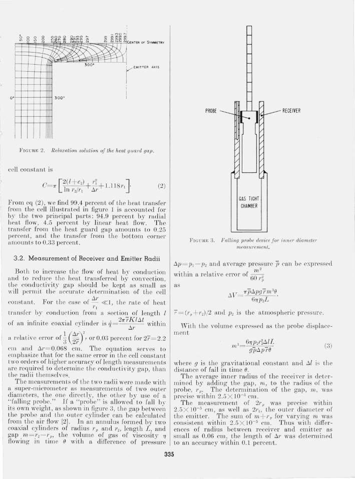
a super-micro meter as m easu ["emen ts of two outer diameters, t he one directly, t he other by use or a "falling probe." If a "probe" is allowed to fall by its own weight, as shown in figure 3, the gap between the probe and the outer cylinder can be calculated from the air flow [2]. In an annulus formed by two coaxial cylinders of radius Tp and T2, length L, and gap m = 1'2-1'p, the volume of gas of viscosity 7)
flowing in time e with a difference of pressure
PROBE ___
GAS TIGHT CHAMBER
F I G UR E 3. Falling probe device fo r i nnel' diameter measurement.
ilp= PI - P2 and average pressure p can be expressed " 2
within a relati ve elTor or 6mo 0' r-" as
IiVith the volume expressed as the probe displacement
67)P2~illL gpilpTe
(3)
where g is the gravitational constant and ill is th e distance of fall in time e.
The average inner radius of the receiver is determined by adding the gap, m, t o the radius of t he probe, r p. The determination of the gap, m , was precise within 2.5 X 10- 5 cm.
The measurement of 21'" was precise withill 2 .5 X 10- 5 cm, as well as 21'1, the outer diameter of the emitter. The sum of m + Tp for varying m was consistent within 2.5 X lO- 5 cm. Thus with differences of radius between receiver and emitter as small as 0.06 cm, t he length of il1' was determined to an accuracy within 0.1 percent.
335

4 . Convection
In general , the hydro dynamical equation for 110nturbulent flow of a fluid of velocity V, viscosity 1/ , pressure p, and density p is (div '1/ grad) v= grad p-pg, where 9 is the acceleration of gravity [3]. For t wo infinite vertical plates at uniform temperatures to - l1t /2 and to+ l1t/2 , the equat ion reduces to
The axes are taken with the origin at the midpoint between the planes. The x-axis is n ormal to the planes, the y-axis is horizontal, and the z-axis is vertical. The average density, p is the density at x = O.
If the separation or the planes is !1r t (x) = to+ xl1t , 111'
and
_[ ( )] _ paxl1t 1 (Op) p= p I - a i - to = p- --' where a = -= - . 111' poi p
111' . 111' Since v= O when x=-2 and x= 2'
(6)
I!1 a closed system, the circulation takes place as a smgle stream , reversin g direction at the top and bottom. Conservation of mass requires a term second order in I1t which does not affect the heat transport by more than 1 percent for actual measurement, hence it was n eglected. The heat transported per unit horizontal ciistance is
q= cp v(x) p(x) l1i (x)clx=-' p p f /IT /2 111'3g a 2C I1t 2
- t. /r 2 720 '1/
whm:e c~ i~ th~ specifi? heat capacity and the average denSIty IS mdlcated wIthout the bar. The horizontal distance in the cell is very nearly 27T"f . Then the rate of heat transport p er degree is
2 - 11 3 2 ' /l1t - 7T"1' l' 9 ap Cp l1t , q 720 1/
(7)
If the total heat transfer is studied as a "conductivity," ql Cl1t , a portion is du e to convection , which may be written as
2.6 X 10- 6a p2c pl1t
'1/ (~)
The value 2.6 X 10- 6 combines the con stants of eq (7) and the value of the cell constant C for the cell of figure 1.
The n eglect of terms of higher order in I1t for p(x) affects K conv detectibly n ear the critical point of CO2 , When I1t < 5 deg C, t hese terms need not b e considered for other m easurements to b e reported.
Engineering investig~Ltions of convection haye b een analyzed by use of several correlating functions . It . may seem at times as if serious discrepancies ex~st when. t~e correlation is extended to inappropnate condltlOns. L et us consider three dimensionless quantities :
(1) The Grashof-Prandtl product
9 (111') 3a pZcpl1t.
'l/K ' Gr·Pr (9)
(2) The Gr<1shof numb er
Gr
(3) The R eynolds number
wher e the a v enlgc veloci ty v (!1r)2apgl1t 192'1/ and xo= !1rj2,
Then
R e g(!1r)3ap2/1t
384'1/ 2 (10)
Thus the Grashof number and the R eynolds numb er ar~ f1!-nctionally the .same for a gas in a vertical gap. Wlthm th e range of pressure and temperature such that the Eucken factor , K /'l/c, is a constant and h . ' .' I t at 'Y = cp/cv IS a constan t, the Grashof-Prandtl .
prod1!-ct and the R ernold.s nU~lb er will ser,ve equally well for the correlatlOn of lammar convect lve effects.
The ratio of K con" to K gas can be found by dividing eq (8) by K gas, and is functionally (M /l) (Gr·Pr). It can be seen from eq (8) /K gas that the criterion of Kraussold, that con vection is insignificant 4 fo1' Gr.Pr< 1000, leads to different errol' limits depend~ng upon M /l. ~or the cell of figure 1, Gr·Pr = 1000 lllvolves a rclatnre heat transfer by co nvection of 8X lO- 3 •
R epresenting a. ratio of the heat transport of ~onv.ect,io.n to .conduction , Gr·Pr is a logical conclat mg functIOn lor heat transport by laminar convec- \ tion .. Over the ra~ge of .variables that eq (9)/eq (10) IS a constant , eIther wIll serve as a criterion for th.e. initi a~ion of turbulent convection. Near the I cntlCal pomt, however , Cp--? OO and 'Y--? OO. Since tbe Euck-en factor does n~t vary greatly, Gr·Pr can ' become enormous whlle the R eynolds numbcr remains small. The R eynolds number depends upon the velocity resistance per se, and it is th e fundamental quantity, not Gr 'Pf, which should be used as the criterion for initiation of turbulen t flo\l~ .
Tll!:' purpose of this section is to demonstrate how the data can be treated to give the heat tr ansfer by thermal conduction alone. NIeasurements must be made under conditions of laminar flow. For COz, Onsager an d Watson [4] have shown that with
• Worse yet is the statement that convectio n cloes not exist foJ' Or ·P r<1 000. The author hopes this iclea will take its place with the phlogiston theor)"! '
336

I app,lraLus of t he plallar, verti C~Ll l.\' pr, t urbulencc F commCll ces a t ft value of t he R eynolds numb er of
ftbout 25. Often it is clem' t lw,t R c< < 25. If there is un certftin t.v, th e !:J.t for lrans ition Jro lll lami nar to t urbulell t fiow should be determined experimentally. At co nstant press ure and co n tant a vemge gas temperature, eq (8) indica tes t tl at q/!:J.t versus !:J.t is lin eal' for laminar fiow. By straight line extrapolation of qj !:J.t versus !:J. t to zero !:J.t , tbe heat transport by convection is eliminated .
Th e essential requirements of eq (8) llre co nfirm ed b~' Lb e resul ts. The heat transpor t cOl'/'ehttes well
a pzc !:J.t versus --p- . Th e gj !:J. t versus !:J. t extrapolations
7J are li neftl' withill tIl e precision of tbe data, except
? fo r very large valu es or eq (8) where second order . effects may b e detectible. Tll e values of !:J.t calcuc' lated from eq (10) (indicated by an l),sterisk on
some extrapolation isot herms in the next paper ) are in satisfactolT accord with the experim ental meaSll l'cm en ts.
5 . Asymmetry of the Heat Flow
5.1. Coaxial Centering
If Lb e emi tter is no teen tereel per fectly the geometrical I'act?r ~ f In 1'2 / 1'1 should be replaced by cosh- 1 [(I'~+ri-cl-) /2rlr2], where cl represents t he
l displacernen t of the two axes. For t lte cell 0 I' fLgure ( I , an error of 7 X 10- 4 cm ill t he centering would
make a difference of only olle pn.l' t ill 100,000 in t he cell constant.
5 .2 . Heat Loss From the Bottom of the Emitter
The cell with a single heat gW1rd loses hea t on the bo ttom as well as on t be sides . ' Vit ll a uniform heater winding this leads to an asymmetric temperature distribution , which beco mes h1,rger as t he gas t hermal conductivity beco lnes larger. A re~tso nable approximation permit ting mathematical treatmen t assumes uniform heat :fl ow from t he center heater to the emitter , no heftt fiow on the heat guard end, and t he heat Aow across the conductivi ty gap proportional to t he temperature difference. The solution for t his problem is
where h= AK, A is t he total exterior surface area, K is th e thermal conductivity of t he substance in t he gap , and K A g t he t hermal co nductivity of silver.5
O:=:; z:=:; l
cl>o(l';n) =10 (J'a ,.) [a"K l (ba,,) - hKo (ba,, )]
+ K o(m,,) [a"Il (ba ,,) + hIo (ba,,)]
~ If the cell were made of anothe r material , the correspond ing thermal conductivity would be usec! in place of fe, •.
an¢l (a;n) =(~¢o) v I' r~a
= 11 (aa,,) [anK I (ba,,) - hKo (ba,,)]
- IC (aa,,) [anI 1 (ba,,)+hIo(ba,Jl
and the an are the ordered posiLive roots of h= a" tan (a"l) . The value o( "a~ + h2 is takell positive or negative in accord witll t he sign of sin a nl.
The functions 10, I I, K o, and I{I ar e B essel (unctions of complex argumen t. The res ul t shows tha t the average temperature of the emitter is not at t he cen ter but at
z= 0.66l for K = 5.95 X IO - 5,
z= 0.675l for K = 5.95 X l 0- 4 ,
and z= 0.697l for K = 11.90 X IO - 4 .
Conductivi ties calculated from the average of LiLe top and cen tel' temperatures must be increased by the factor indicated in figure 4. This factor is ftccurate enough t hat usually no significant error is invol vecl , and could be reduced by adding measurement of t he t.emperatme difference at t he bottom of the cell.
6. The "Blank" and Conduction of Pins
vVh en t be cell is evacuftted , the h e~tt t ransfen ed by radiation ftnd by conduction of t he pins can be treated as a measurement of a "conductivi ty," called a " blank. " The presen t cell had a blrtnk at o °C of 0. 138 X 10- 5 cal cm- 1 sec- l deg C- l, about 4 percent of t he conductiviLy o[ CO2 at t he sa me temperature and 1 atm pressure. It was estimated that no more than hal[' of t he heat tran sfer of that blank was due to co nduction of t he pins.
It was assumed that t he conductivity of a gas co uld be fouud by deducting the blank from t ho value of the apparent conducti\Tity for zero tem perat ure difl'erence. However, the blank may Jl ot adequately represent the heat transfer in t he presence of a gas 1'01' the followin g reasons : Or The conduction 0'[ h eat across the pin-emit i e-I" int erface may increase in the presence of a gas .
(2) The temperature distribution in t he pins may per tmb the heat transfer in t he gas significantly.
In the first case, if t.he pressure of t he pins agail1st the em itter is high enough, the efl'ect of t he gas 011
the conduct. ion across the cont.act interface is negligible. Ascoli and Germagnoli [5] showed t hat t he temperat ure difference across a steel-aluminum intc rface with 8 !lin. finish became nearly constant in a vacuum once t he pressure of contact. reached 100 kg/cm2. For N z at 1 atm, the temperat ure differel1 ce across the interface with t he same heat fiux becaill e nearly co nst.ant s,t 50 kg/cm2 contact pressure, and at 100 kg/cm 2 was equal within experimental errol' to t he corresponding vacuum value. Boeschoten all d Van D el' Held [6] found three t imes the heat conduction in t.he presence of 1 atm of helium as in a vacuum at 35 kg-/em2 contact. pressllre. The inferen ce from the preceding investigation is t.hat at 100 kg,lcm2,
337

t he ratio would b e 1.5/1. Rough surfaces approach 1 he b ehavior of smooth surfaces as t he contact press ure is increased. These measurements were performed upon a steel-aluminum in terface rather tban a Pyrex-silver interface used in the presen t apparatus. Ho\vever , the ability of silver to conform to t h e harder surface of Pyrex is at least as gr eat as for aluminum to conform to steel. The pins were forced into the silver sufficiently that indentations 0.003 to 0 .005 in. deep were made in the emitter, which is to say with sufficient force t o exceed 1500 kgjcm2, the tensile stren gth of silvcr. The P yr ex pins were b eld in an aluminum sleeve s uch that the composite expansion of t he two materials approximately matches t he expansion of t h e cell material from 0 to 400 °0. Consequently the centering of the emitter and th e contact pressure between the pin and t he emitter should b e maintain ed over t h e temperature range. Hence i t can b e expected that gases of low conductivity caused an insignificant change in tbe rate of t ransfer of heat through the pins. 1n helium , the uncertainty in pin conduction should no t exceed 0 .1 percent of the gas conduct ion.
The adclitional heat transfer through t he gas, which arises because the temperature di stribution in t h e pins does not follow th e radial gradien t, can b e evaluated b y relaxation methods, and leads to the rpsult t hat an 18 percen t increase of conduction for the area of t he surface occupied by t he base of t h e pin will b e observed when the conductivity of th e gas is 10 percent that of P~Tex. The area occupi ed by the bases of seven pin s was 0.4 percent of the total urface area of t he receiver so t hat at a gas con
ductivity of 3 X 10- 4 cal cm- 1 sec - 1 deg 0 - 1 an increase o f conduction of 0.07 percen t will be observed. If t h e conductivity oJ t h e fluid reached t he value of P yrex, t h e pins would have no effect on th e temperature gradient , and at low values of gas conductivity, t h e effect is about the same as at a conductivi ty o f 3 X 10- 4 cal cm- 1 sec - [ deg 0 - 1 •
7 . Radial Temperature Gradient in the Emitter and Receiver
A correctioll , in general small , must b e made for the fact that th e thermocouples are placed in t he body of t h e emitter and receiver . This is a power series o f I<'co rr= K meas [1 + aKmeas+ (aKmeas)2+ . . . J of which only the first corrective term is large enough t o be significant. For the dimensions of the silver conductivity cell in figure 1, a= 10.70 cm sec deg C /cal.
8 . Discussion of Other Cells
There are only a few form s of th ermal conductivity cells suitable for accurate absolute determinations of t he thermal conductivit.y of gases. The "hot wire" cell is an extreme case of a coaxial cylinder cell , with a small radius of t he emitter, but t h e cell constant cannot b e determined with the accuracy possible for a larger radius of em itter. The heat transfer analysis is complicated, and in a dense gas convection is difficult to control because of lhe large temperature gradiellt near the wire.
I -+
, ~ r I
I:,
12 0
1
FIGURE 4. Correction to the conductivity for asymmetric heal ~ flow .
A coaxial cylinder cell wi th h eat g uard s at both ends would not b ave th e end h eat flow which requires the corrections given in figure 4. However , there is ftn uncer tainty in the results due to a possible h eat flow b etween th e emitter and h eat guard s. When tb e emi tter is susp ended or h eld in place by slec \'e <;, or rod connections with t he heat guards (as is custom ary for this d esign) , the increased condu ction possible by a slight difference in temperature between the emitter and guards will increase sign ificantly the uncertainty of t he thermal conductivity determination. The uncer tainty is reduced if the thermal conductivity is relatively large, and if the emitter-receiver temperature difference is large. In order to avoid these restrictions, the susp ension m ethod could probably be modified .
In prin ciple the flat plate cell , with an emi tter and guard above th e r eceiver, should not b e affected by convection . In dense gas , there is good possibility that m ftny such cells have had significant convection transfer from "ehimn eys," bu t that no special m easurem ents were made to ch eck . However, by prop er design , it call be exp ected that convection difficulties would be eliminated . The cell con stant can be d etermin ed with about the same accuracy as for the coaxial cylind er cell , bu t instability of th e flat plate cell alinement aff ects th e cell constant directly. By contrast, a change of the coaxial cylinder cell alinem en t affects th e cell constant comparatively little.
9. Conclusions
By use of ft h eat guftrd and receiver extension which extends th e conductivity gap of a coa.xial cylinder , t he conduction acros.s t~le gap ean .be expressed accurately. In COmbll1atlOn With sp eCial m easuring techniques involving a "falling probe," the value of th e cell constant can be obtained to an accuracy within ± 0.1 percent.
The coaxial cylinder cell must b e used wi th the axis vertical in order to permit analysis of convective h eat t ransport. It was deduced mathematically and found experimen tally that tb e apparent conductivity is affected by laminar con vection linearly with th e temper ature difference. The t emperature difference which causes t he R eynolds number , eq (10), to be
338

25 defines Lh e Jlighest tempera ture difl'el'en ce [or whi ch lnminar flow can be expected. The efrecLs of convecLion can be elim ina,ted by exLrn,po]n,t ing t he a,pparent conel uc tivit~T versus t he t emperaturc difference Lo zero temperature ciifl'el'encc, pl'ovidcd lli e m easurements lie in th e mnge of hLminar flow.
For high accurac~- , correction s must be mltd e to tl le daLa for ns~·mmetr~· of h eat flow , p el'Lurb,tt ion of t he temperature gradient by th e mountin g pin s, <1l1el the temp erature gradient ill the emitter n,nci receiver. O[ course, t]l e rate of heat Lmnsfel' in a vacuum is d edu cted. Ther e has now been sufficient quantiLative meitSUrement to show that the radiation and pin tran s fer should remain constant within 0.1 percen t in th e presence of a gas.
Of th e various types of cells used for m easuring t he th ermal cOllduetiviL~- of gases, the coaxial cylind er cell and the flat plu te cell oHer the most promise of accu rate results.
10. References [1] H . S. Carslaw a nd J . C . J aeger, Conduction of heat in
solids, 2d Ed., Oxford U ni v. Press, London, 195!J. [2] W. 1-1. MacAdams, H eat transmission, 2d Ed. , McGraw
Hill Book Co., Inc., N ew York, 1942. [3] R . C. J ones a nd W . H. Fur ry, R ev . Mod . Phys. 18, 151
(1946). [4] L . Onsager and W. W. Watson, Ph ys . Rev. 56, 474 (1939). [5] A. Ascoli a nd E. Ger magnoli , E ner gia N ucleare 3, 113
(1956) . [6] F. Boeschoten " nd .8. F. :\1 . Va n Der Held, Physica 23,
37 (1957).
II. Appendix
Given t he conductivity gap h and heat guard gap 2lc. 6 vVe idenLify the poin ts, ARC DE F G H in t he complex z-phlne. These poin ts are transformed in the t-ph-we by t he Schwnl'z-Christoffel tmnsformutiol} , which is
D C i z-plll np
?/ z= .t+ iy
H A
0 , 0 .r -t--
la JJ
E F
6 Xote tha t the symbo lism is thnt of Ca rsla w and Jaegrl', a nd in general sh ou ld not be identi fied with t he symbolism of t he rest of the pa per.
PoinLs A , Fl, C, V , E, fLncl F flr e nssumed to lie at infinity in t he z-plitne. Corres ponding vfllues oi' the points arc s ltown for t he I-plnne.
I -plaLlc t = l+i~
A 13 (",D 0, ° E ,F G II co
-::----
- 1 - a ° ° a 1 - co
By use oi' t ile co ni'ormal Il1n pplllg i' Ull ction
7rw= ln (t+ a)/(t - a)
the points in t lle z-plane fLre trans ronn ed Lo Lhe ineliCttted poin ts in t he w-pl ane.
- co
l)
w-plnn c
w= ,..+ ir
~ l , I II 1" ---o~I---CO-------co
o 0 E - co - ~;---------=-O ' I -i co ,-i
Thus in t he w-plfLu e, i1 enL flo,,· between two in fillite parallel plates can be studied.
II' Lh e i1 eH L now to w= u -i is studied , t his corres ponds to t he heat flow to DE= -iy ill t he z-plan e.
B ·b·· I (t + a) I . . - v su st lLullnoO' 7rW = n -- ane w=u-~, z= -~y, . t - a
For u (and y) huge, t ----7+ a-
2ik. I + h - - S II) - I . 7r
11, 2k . ?J = hu+- ln (J - aZ) +- sm - I a.
7r 7r
The h eat transport to DE per unit width per unit temperature difference is, in t he w-pla ne, Ku (where K is the thermal conductivity of t he medium) .
Thus, ther e are two corrective tenns to h e added to t he norm al term y/h for t he steady heitt flow bet ween two pla nes clistan t h apart. For the case that the heat guard gap (2lc) is equal to the conductivity gap ell,)
339

Where the conduction is regarded as unperturbed along FG and HO, we can get a relative correction to the normal term for infinite plates over t he distance of the heat guard gap by taking y = 2k = h. Then
or we may add a length to the emitter equal to one
half the heat guard gap times the factor in parenthesis, i.e.,
= k(l - O.0766) = O.9234k.
(Paper 6GA4-] GR)
340