Embed Size (px)
Citation preview

Written by George Spais, Senior Mechanical Engineer
W H I T E PA P E R
USA Tolerance Rings : 85 Route 31 North | Pennington, NJ 08534 | 609.745.5000 usatolerancerings.com
PAGE 1
500
300
100
100 150 200 250
Temperature 0F
With Tolerance Ring
Pres
sing
For
ce lb
s.
Without Tolerance Ring
Without Tolerance Ring
These unique circular fasteners can secure and mount ball bearings within housings or to shafts by exerting radial holding forces. A series of equally spaced waves or corrugations formed into their circumference act as springs to retain ball bearings in place. The amount of compres-sion of these waves, the inherent properties of a particular tolerance ring configuration, and the properties of the mating surfaces determines the holding force strength.
Thermal Expansion & ContractionRetaining a ball bearing can be difficult when wide service tempera-ture ranges are encountered, especially with aluminum, magnesium or plastic housings. Unless the housing material has a coefficient of thermal expansion similar to that of the ball bearing races, a typical press fit (PF) or a slip fit at room temperature can loosen at higher temperatures. The amount of retention force loss is further exacerbated with increasing ball bearing diameters. This problem results first in outer race slippage then eventual destruction of the ball bearing and component surfaces.
The graph below illustrates tolerance ring (TR) performance in retaining a 6205 ball bearing (about a 2.00” OD) in an aluminum housing. With a 0.0012” interference fit, an installation force of 500 pounds is re-quired. Due to thermal growth between the steel bearing and aluminum housing, the bearing becomes loose at a temperature of 170°F. With the TR, an initial installation force of only 320 pounds is required, and axial retention remains high at 230 pounds around 270°F.
Tolerance Rings can save your design when mounting ball bearings.
AN STYLE R INGS Waves on inside, typically for securing bearing
outer race to housing bore
BN STYLE R INGS Waves on outside, typically for securing
bearing inner race to shaft
Written by George Spais, Senior Mechanical Engineer
W H I T E PA P E R
USA Tolerance Rings : 85 Route 31 North | Pennington, NJ 08534 | 609.745.5000 usatolerancerings.com
PAGE 2
Reduction Of Tight TolerancesWith a PF of ball bearings upon steel components, achieving the tight tolerances of a few ten thousandths of a inch (0.0001”) on mating components (i.e., shaft, housing) can be costly, especially when ground finished surfaces are required. Implementing TRs allows for the relaxing of component diametric tolerances to a few thousands of an inch (0.001”). Often, the tolerances can be relaxed by a factor of ten when requirements go from a ground surface to a machined surface. In housings containing small nicks, dents or burrs, a TR provides an overlaying surface that compensates for finish irregularities. Relaxing tolerances through the use of TRs can result in reduced component production costs.
Handling Of Radial Loads For typical ball bearing applications, the radial capacity is con-sidered constant for a given configuration, provided the waves remain within their elastic range. Depending on the amount of initial wave compression and if the waves are still within their elastic limits, there may be some movement away from center when a radial force is applied. The loading point at which move-ment occurs can be adjusted for and it is directly related to the TR’s spring rate, the amount of initial wave compression induced at assembly, and the magnitude of the applied radial load.
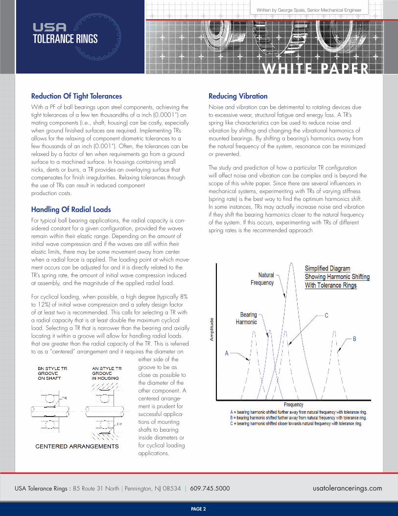
For cyclical loading, when possible, a high degree (typically 8% to 12%) of initial wave compression and a safety design factor of at least two is recommended. This calls for selecting a TR with a radial capacity that is at least double the maximum cyclical load. Selecting a TR that is narrower than the bearing and axially locating it within a groove will allow for handling radial loads that are greater than the radial capacity of the TR. This is referred to as a “centered” arrangement and it requires the diameter on
either side of the groove to be as close as possible to the diameter of the other component. A centered arrange-ment is prudent for successful applica-tions of mounting shafts to bearing inside diameters or for cyclical loading applications.
Reducing Vibration Noise and vibration can be detrimental to rotating devices due to excessive wear, structural fatigue and energy loss. A TR’s spring like characteristics can be used to reduce noise and vibration by shifting and changing the vibrational harmonics of mounted bearings. By shifting a bearing’s harmonics away from the natural frequency of the system, resonance can be minimized or prevented.
The study and prediction of how a particular TR configuration will affect noise and vibration can be complex and is beyond the scope of this white paper. Since there are several influencers in mechanical systems, experimenting with TRs of varying stiffness (spring rate) is the best way to find the optimum harmonics shift. In some instances, TRs may actually increase noise and vibration if they shift the bearing harmonics closer to the natural frequency of the system. If this occurs, experimenting with TRs of different spring rates is the recommended approach
Written by George Spais, Senior Mechanical Engineer
W H I T E PA P E R
USA Tolerance Rings : 85 Route 31 North | Pennington, NJ 08534 | 609.745.5000 usatolerancerings.com
PAGE 3
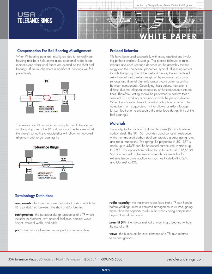
Compensation For Ball Bearing MisalignmentWhen PF bearing pairs are misaligned due to non-collinear housing and bore hole center axes, additional radial loads, moments and vibrational forces are exerted on the shaft and bearings. If the misalignment is significant, bearings will fail prematurely.
The waves of a TR are more forgiving than a PF. Depending on the spring rate of the TR and amount of center axes offset, the wave’s spring-like characteristics will allow for improved alignment and longer bearing life.
Preload BehaviorTRs have been used successfully with many applications involv-ing preload washers & springs. The precise behavior is rather intricate and each scenario depends on the assembly method-ology and the component properties. Typical influencing factors include the spring rate of the preload device, the encountered axial thermal strain, axial strength of the raceway ball contact surfaces and thermal diametric growth/contraction occurring between components. Quantifying these values, however, is difficult due the relational complexity of the component’s interac-tions. Therefore, testing should be performed to confirm that a selected TR is working in conjunction with the preload device. When there is axial thermal growth/contraction occurring, the objective is to incorporate a TR that allows for axial slippage (a.k.a. float) prior to exceeding the axial load design limits of the ball bearing(s).
MaterialsTRs are typically made of 301 stainless steel (SST) or hardened carbon steel. The 301 SST provides good corrosion resistance while the hardened carbon steel can provide greater spring rates and radial capacities. The spring like properties of 301 SST is stable up to 450°F and the hardened carbon steel is stable up to 250°F. For applications calling for softer material, 316/316L SST can be used. Other exotic materials are available for extreme temperature applications such as Hastelloy® C-276 and Monel® K-500.
Terminology Definitions
components - the inner and outer cylindrical parts in which the TR is sandwiched between; the shaft and/or bearing.
configuration - the particular design properties of a TR which includes its diameter, raw material thickness, nominal wave height, material width, and pitch.
pitch - the distance between wave peaks or wave valleys.
radial capacity - the maximum radial load that a TR can handle before yielding; unless a centered arrangement is utilized, going higher than this capacity results in the waves being compressed beyond their elastic range.
press fit (PF) - the typical method of mounting a bearing without the use of a TR.
wave - the bumps on the circumference of a TR; also referred to as corrugations.

Written by George Spais, Senior Mechanical Engineer
W H I T E PA P E R
USA Tolerance Rings : 85 Route 31 North | Pennington, NJ 08534 | 609.745.5000 usatolerancerings.com
PAGE 4
Formulas, Derivations & Theory
Theoretical Spring Constant Of A Single Wave - “little k” k = Eaw(t/p)3
Theoretical Spring Rate Of The Whole Tolerance Ring - “big K” The spring rate encountered when one cylindrical component is compressed radially relative to the other. K = FR/Δy = nk/5 — typically used when waves are lightly compressed (1% to 5% wave deflection) K = FR/Δy = 2nk/5 — typically used when waves are heavily compressed (12% to 16% wave deflection) Interpolation for K based on wave compression between nk/5 and 2nk/5 is permissible.
Theoretical Circumferentially Distributed Radial Load Between Components After Assembly FC = nkΔy
Theoretical Axial Retention Force Between Components FA = μSFC
Theoretical Radial Capacity For Typical Ball Bearing Applications FM = nk(0.18h)/5
Variable Definitions
E = Modulus of Elasticity or Young’s Modulus, typically 28x106 psi for 301 stainless steel t = strip or raw material thickness before it is fed into forming machines p = pitch; distance between peak to peak or valley to valley of the waves w = effective wave width a = adjustment constant based on heuristic data; typically averages at 4.8 but can be lower or higher* n = number of waves on circumference FR = radial resistive force exerted by tolerance ring when one component is radially moved relative to the other Δy = amount of wave deflection from free state; this value is dependent on component diameters μS = static coefficient of friction; typically 0.15 for lubricated steel on steel h = reference nominal wave height
* The adjustment constant “a” is based on heuristics and historical experimental results. It is applied to compensate for variations in the waves’ cross sectional thickness and geometry at various locations. Even though a particular raw material thickness is fed into forming tools, the corrugating operation induces local material elongation & contraction during the cold rolling process which changes the cross-sectional profile. The amount of elongation & contraction occurring is influenced by the interplay of the raw material properties of a particular metal heat number, tolerances of the raw material’s thickness, the forming tools selected, the amount of force applied during the cold forming process and the feed speed. Predicting the profile at incremental cross sections is beyond the scope of reason. Therefore, theoretical calculations or finite element analysis should be used for guid-ance purposes only since they often provide rough approximations. Testing a particular tolerance ring between production components throughout the design constraint limits and environmental conditions is the best way to validate performance.
Theoretical Wave Cross-sectional Profile Assumes Uniform Thickness
Actual Wave Cross-sectional Profile Contains Thickness Variations