Embed Size (px)
Citation preview
Thermal Losses via Large Slabs on Grade
P. Brinks1,2*
, O. Kornadt1, and R. Oly
2
1 TU Kaiserslautern, Department Building Physics / Low-Energy Buildings, Germany
2 Lindab S.A., Astron Research & Development, Luxembourg
ABSTRACT
Thermal losses via slabs on grade are usually calculated by simplified steady state
calculations such as described in ISO 13370 or ASHRAE Fundamentals. In this research such
standard methods were compared to transient simulations using a finite difference model
coupled with building simulation software. The focus was on large slabs up to 10000 m2 to
analyze the thermal transport in particular under industrial buildings. To respect real
conditions of such buildings also lower inside temperatures than in dwellings were assumed.
Moreover different insulation types and soil qualities were compared. The simulations in
general showed good accordance with the ISO-method for small horizontally insulated slabs
like dwellings at 20 °C inside temperature. For large slabs and in particular for non-insulated
slabs the losses seemed to be far overrated by the steady state method, in particular for large
low heated buildings such as warehouses. Here a lot of energy from summer overheating of
the building is stored under the slab and causes a heat flow from the ground back into the
building during the first months of the heating period and not inverse. Therefore short vertical
footer insulations appear most energy efficient for most large industrial buildings.
KEYWORDS
Thermal losses via ground, industrial buildings, large slabs, building simulation,
transient ground modeling
INTRODUCTION
For building components above grade, thus adjacent to external climate (e.g. walls
and roofs), it is simple to calculate the thermal transport during the year as inside and
outside temperatures can be assumed easily. For slabs on grade or even below-grade
components the outside conditions cannot be determined that easily. The temperature
under the slab is different at every position and significantly depends on the slab
dimensions, the distance to the perimeter, the climate, the heat storage capacity and
conductivity of the soil, the quality of slab insulation, the buildings inside temperature
and many more parameters. For buildings with a low ratio of ground-coupled floor
area to heated building volume a precise assessment of the thermal transport via slabs
is minor important. But for industrial buildings like large warehouses or production
* Corresponding author email: [email protected]
427
buildings the imprecision in assessing such losses can have a significant impact on the
total energy balance. Due to the complex boundary conditions several simplified
methods exist, reaching different accuracies in estimating the thermal transport via
ground. The simplest way to consider the ground´s insulation effect is the use of
correction coefficients, still used in some energy balance methods such as DIN V
18599 (2011) in Germany. Also more precise steady-state methods assuming a
periodic thermal transport via soil can be used such as the American method
introduced in ASHRAE (2001). In Europe a similar method is described in EN ISO
13370 (2007) which is mostly based on the findings in (Anderson 1991), (Claesson
und Hagentoft 1991) and (Hagentoft und Claesson 1991).
With an increasing computational power the most precise methods were developed in
recent years. These 3D finite difference models are able to couple the transient ground
heat transfer with a building simulation software package. Such coupled
slab-on-grade models allow the interaction of building and ground, recognizing
storage effects and thermal properties of the soil. Overviews and comparisons of
different ground coupling models are given in (Chen 2013) and (MCDowell et al.
2009). Unfortunately these references just outline small slabs of residential buildings
up to 144 m². Large slabs of industrial buildings can arise some 10000 m² or more.
Thus further comparisons were carried out in this project. Here the finite difference
model implemented into TRNSYS 17 (type 49) is compared with the simplified
method of EN ISO 13370 (2007) as imprecisions of the ISO-method for industrial
buildings are already claimed in (Brinks et al. 2014). But the focus of this project is
not in estimating the precision of existing steady-state methods but in finding best
insulation solutions for large slabs on grade for the industrial building sector.
Furthermore the variation of the inside temperature is an important parameter as
temperatures in warehouses and production buildings usually are in a low range
between typically 12 °C and 20 °C dependent on their usage. Hence the temperature
difference between inside air and ground is often far lower than for residential
buildings. Therefore it is to clarify if horizontal insulations are a reasonable solution
for large slabs under low heated buildings, as often required by existing national
energy regulations.
STEADY STATE METHOD VERSUS TRANSIENT SIMULATION
EN ISO 13370 (2007) gives an analytic approach that is implemented in many energy
balance software packages to estimate thermal losses via ground for the European
wide required energy performance certificates. Here the variation of the heat flow is
described by cosine functions, representing the thermal flow oscillation due to
changing in- and outside temperatures. Further the periodic shift, caused by the slow
thermal transport via ground, is recognized by an interval of approximately 1-2
months. However in such steady state approaches it is not considered that energy is
stored in the ground during summer. For the here carried out transient simulations
type 49 of the TRNSYS 17 software package is used. This type is a 3D finite
428
difference model of the ground under a slab on grade. It is coupled with the thermal
transport via slab and thus interacts with the transient building simulation. Therefore
all gains from summer overheating of the building are considered in the model. The
discretization of soil can be chosen as well as the dimensions of the ground cube
under the building. The model accounts only for thermal transport by conduction,
moisture effects as well as water movements in soil are neglected. Other thermal
properties like conductivity and heat capacity can be chosen freely. All boundary
conditions between the discretized ground (near field) and the ambient soil (far field)
are assumed according to the Kusuda equation (Kusuda and Achenbach 1965) for
undisturbed ground temperatures. The differential equations describing the thermal
transport in this model are solved analytically. All discretized nodes are assumed with
a cubic shape, why six heat transfers must be analyzed per node. For further
description it is referred to the mathematical reference of type 49 (Solar Energy
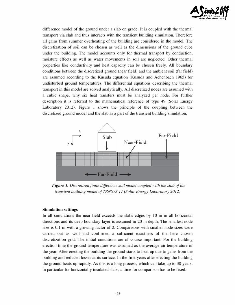
Laboratory 2012). Figure 1 shows the principle of the coupling between the
discretized ground model and the slab as a part of the transient building simulation.
Figure 1. Discretized finite difference soil model coupled with the slab of the
transient building model of TRNSYS 17 (Solar Energy Laboratory 2012)
Simulation settings
In all simulations the near field exceeds the slabs edges by 10 m in all horizontal
directions and its deep boundary layer is assumed in 20 m depth. The smallest node
size is 0.1 m with a growing factor of 2. Comparisons with smaller node sizes were
carried out as well and confirmed a sufficient exactness of the here chosen
discretization grid. The initial conditions are of course important. For the building
erection time the ground temperature was assumed as the average air temperature of
the year. After erecting the building the ground starts to heat up due to gains from the
building and reduced losses at its surface. In the first years after erecting the building
the ground heats up rapidly. As this is a long process, which can take up to 30 years,
in particular for horizontally insulated slabs, a time for comparison has to be fixed.
429
Here all selected simulation results are shown in the fourth year. This seems to be a
good compromise, as at this time the ground is already close to steady state condition
but the simulation time is still acceptable.
Four different building sizes were chosen for simulation to represent a typical range
of industrial building sizes (1000 m² - 10000 m²). The length/width ratio for all
buildings is 2.2:1 and the buildings comply with the currently required thermal
standard in Germany EnEV 2014 (2014). To represent typical summer overheating, all
buildings have the same dome light area of 9% related to the ground area. Further the
walls and roofs are made of light steel structure components (profiled sheeting and
mineral wool insulation). All simulations were carried out with the German reference
climate for the city of Potsdam (TRY 2010: average temperature 9.54 °C, amplitude
9.01 °C). The soil parameters conductivity and heat capacity have a significant impact
on the thermal transport. EN ISO 13770 suggests standard values for clay, sand and
rock, these values were used for the soil comparison in figure 6. For all other
simulations a sand ground was assumed as it is also the standard assumption of EN
ISO 13370. All thermal properties are listed in table 1.
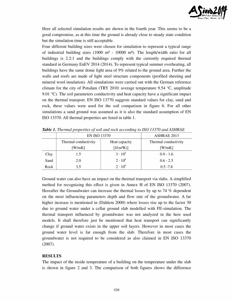
Table 1. Thermal properties of soil and rock according to ISO 13370 and ASHRAE
EN ISO 13370 ASHRAE 2013
Thermal conductivity
[W/mK]
Heat capacity
[J/(m³K)]
Thermal conductivity
[W/mK]
Clay 1.5 3 · 106 0.9 - 1.6
Sand 2.0 2 · 106 0.6 - 2.5
Rock 3.5 2 · 106 0.5 -7.8
Ground water can also have an impact on the thermal transport via slabs. A simplified
method for recognizing this effect is given in Annex H of EN ISO 13370 (2007).
Hereafter the Groundwater can increase the thermal losses by up to 74 % dependent
on the most influencing parameters depth and flow rate of the groundwater. A far
higher increase is mentioned in (Dahlem 2000) where losses rise up to the factor 30
due to ground water under a cellar ground slab modelled with FE-simulation. The
thermal transport influenced by groundwater was not analyzed in the here used
models. It shall therefore just be mentioned that heat transport can significantly
change if ground water exists in the upper soil layers. However in most cases the
ground water level is far enough from the slab. Therefore in most cases the
groundwater is not required to be considered as also claimed in EN ISO 13370
(2007).
RESULTS
The impact of the inside temperature of a building on the temperature under the slab
is shown in figure 2 and 3. The comparison of both figures shows the difference
430
between using horizontal insulation or a vertical footer insulation. Due to the high
conductivity of the concrete slab much more energy from summer overheating is
stored under the building if no horizontal insulation exists. Thus during the heating
period the temperature difference between the required inside temperature and the soil
temperature is much lower when only footer insulation is used.
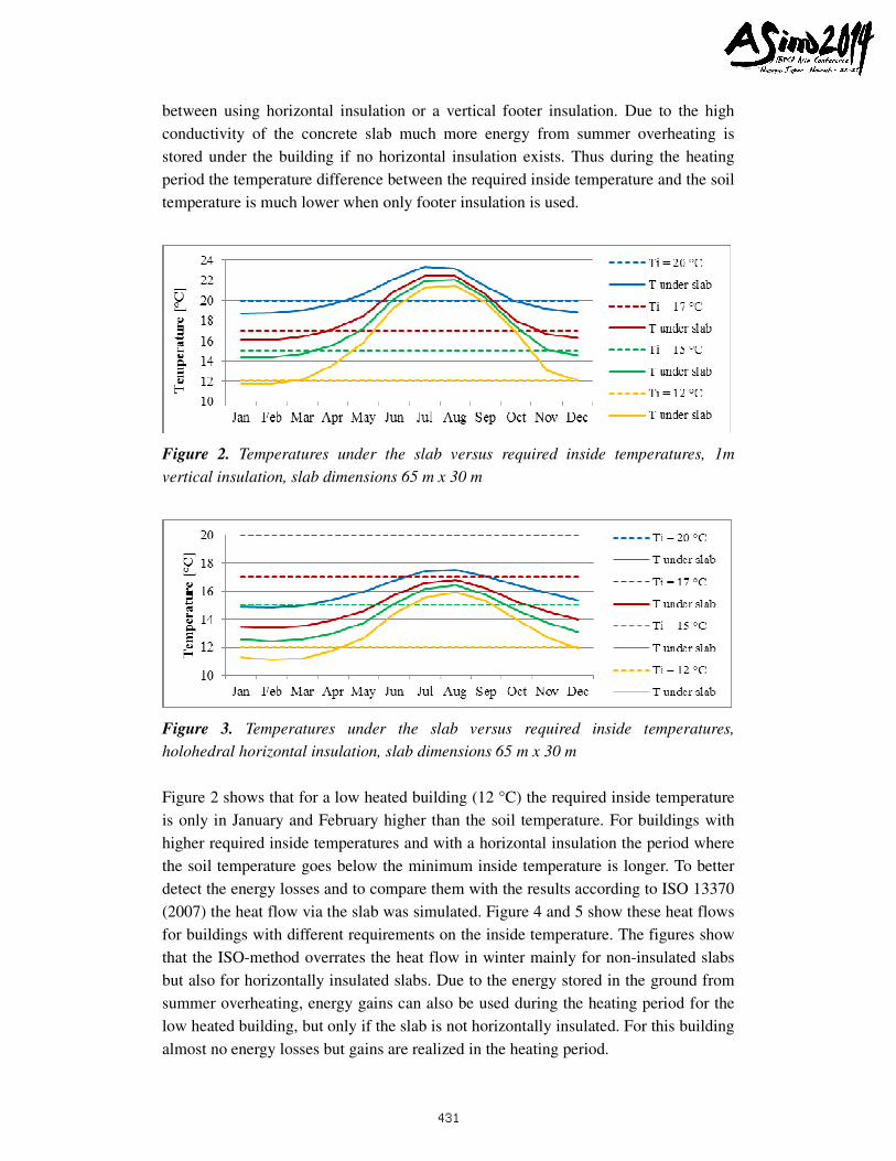
Figure 2. Temperatures under the slab versus required inside temperatures, 1m
vertical insulation, slab dimensions 65 m x 30 m
Figure 3. Temperatures under the slab versus required inside temperatures,
holohedral horizontal insulation, slab dimensions 65 m x 30 m
Figure 2 shows that for a low heated building (12 °C) the required inside temperature
is only in January and February higher than the soil temperature. For buildings with
higher required inside temperatures and with a horizontal insulation the period where
the soil temperature goes below the minimum inside temperature is longer. To better
detect the energy losses and to compare them with the results according to ISO 13370
(2007) the heat flow via the slab was simulated. Figure 4 and 5 show these heat flows
for buildings with different requirements on the inside temperature. The figures show
that the ISO-method overrates the heat flow in winter mainly for non-insulated slabs
but also for horizontally insulated slabs. Due to the energy stored in the ground from
summer overheating, energy gains can also be used during the heating period for the
low heated building, but only if the slab is not horizontally insulated. For this building
almost no energy losses but gains are realized in the heating period.
431
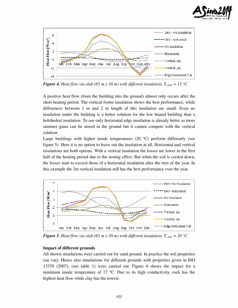
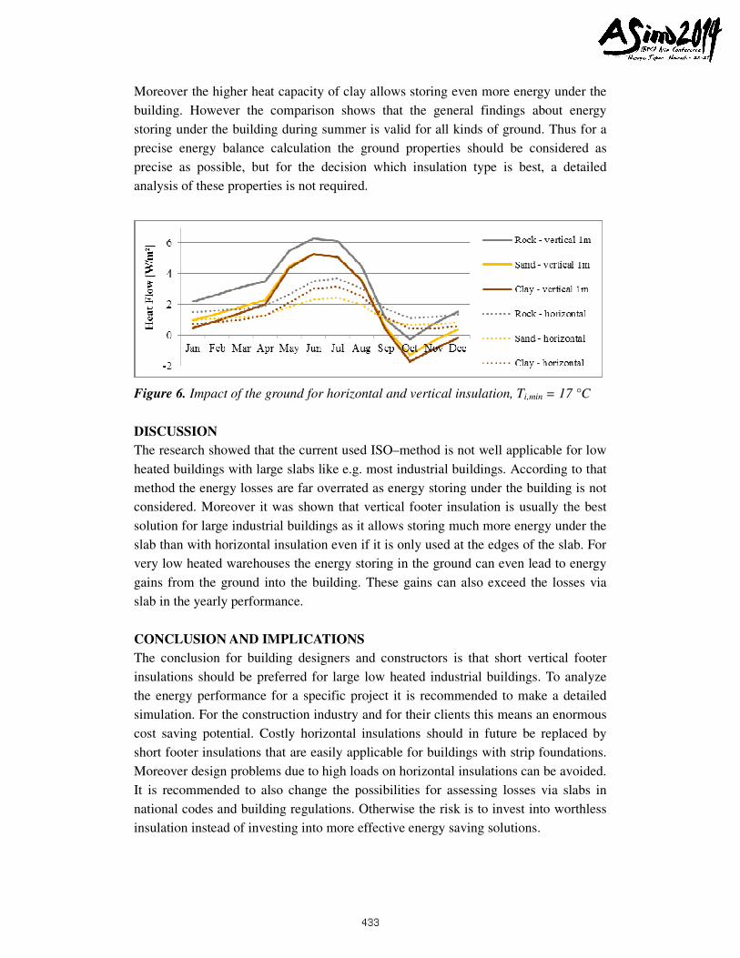
Figure 4. Heat flow via slab (65 m x 30 m) with different insulation, Ti,min = 12 °C
A positive heat flow (from the building into the ground) almost only occurs after the
short heating period. The vertical footer insulation shows the best performance, while
differences between 1 m and 2 m length of this insulation are small. Even no
insulation under the building is a better solution for the low heated building than a
holohedral insulation. To use only horizontal edge insulation is already better as more
summer gains can be stored in the ground but it cannot compete with the vertical
solution.
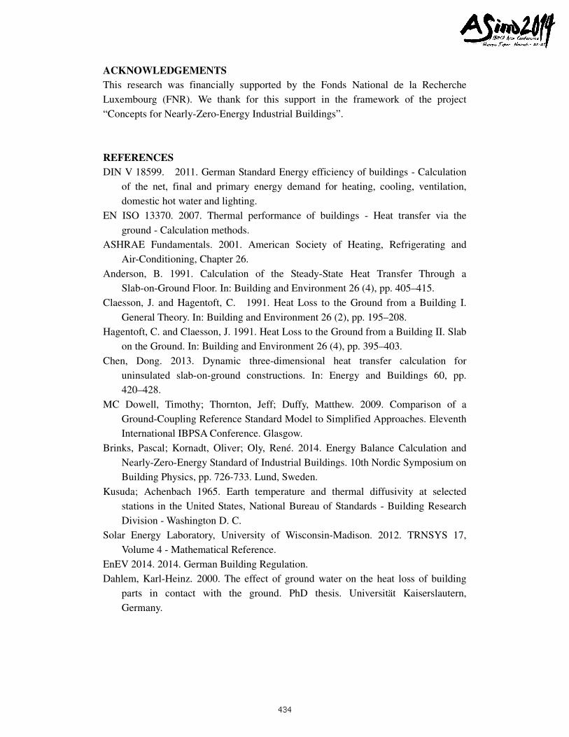
Large buildings with higher inside temperatures (20 °C) perform differently (see
figure 5). Here it is no option to leave out the insulation at all. Horizontal and vertical
insulations are both options. With a vertical insulation the losses are lower in the first
half of the heating period due to the storing effect. But when the soil is cooled down,
the losses start to exceed those of a horizontal insulation after the turn of the year. In
this example the 2m vertical insulation still has the best performance over the year.
Figure 5. Heat flow via slab (65 m x 30 m) with different insulation, Ti,min = 20 °C
Impact of different grounds
All shown simulations were carried out for sand ground. In practice the soil properties
can vary. Hence also simulations for different grounds with properties given in ISO
13370 (2007), (see table 1) were carried out. Figure 6 shows the impact for a
minimum inside temperature of 17 °C. Due to its high conductivity, rock has the
highest heat flow while clay has the lowest.
432
Moreover the higher heat capacity of clay allows storing even more energy under the
building. However the comparison shows that the general findings about energy
storing under the building during summer is valid for all kinds of ground. Thus for a
precise energy balance calculation the ground properties should be considered as
precise as possible, but for the decision which insulation type is best, a detailed
analysis of these properties is not required.
Figure 6. Impact of the ground for horizontal and vertical insulation, Ti,min = 17 °C
DISCUSSION
The research showed that the current used ISO–method is not well applicable for low
heated buildings with large slabs like e.g. most industrial buildings. According to that
method the energy losses are far overrated as energy storing under the building is not
considered. Moreover it was shown that vertical footer insulation is usually the best
solution for large industrial buildings as it allows storing much more energy under the
slab than with horizontal insulation even if it is only used at the edges of the slab. For
very low heated warehouses the energy storing in the ground can even lead to energy
gains from the ground into the building. These gains can also exceed the losses via
slab in the yearly performance.
CONCLUSION AND IMPLICATIONS
The conclusion for building designers and constructors is that short vertical footer
insulations should be preferred for large low heated industrial buildings. To analyze
the energy performance for a specific project it is recommended to make a detailed
simulation. For the construction industry and for their clients this means an enormous
cost saving potential. Costly horizontal insulations should in future be replaced by
short footer insulations that are easily applicable for buildings with strip foundations.
Moreover design problems due to high loads on horizontal insulations can be avoided.
It is recommended to also change the possibilities for assessing losses via slabs in
national codes and building regulations. Otherwise the risk is to invest into worthless
insulation instead of investing into more effective energy saving solutions.
433
ACKNOWLEDGEMENTS
This research was financially supported by the Fonds National de la Recherche
Luxembourg (FNR). We thank for this support in the framework of the project
“Concepts for Nearly-Zero-Energy Industrial Buildings”.
REFERENCES
DIN V 18599. 2011. German Standard Energy efficiency of buildings - Calculation
of the net, final and primary energy demand for heating, cooling, ventilation,
domestic hot water and lighting.
EN ISO 13370. 2007. Thermal performance of buildings - Heat transfer via the
ground - Calculation methods.
ASHRAE Fundamentals. 2001. American Society of Heating, Refrigerating and
Air-Conditioning, Chapter 26.
Anderson, B. 1991. Calculation of the Steady-State Heat Transfer Through a
Slab-on-Ground Floor. In: Building and Environment 26 (4), pp. 405–415.
Claesson, J. and Hagentoft, C. 1991. Heat Loss to the Ground from a Building I.
General Theory. In: Building and Environment 26 (2), pp. 195–208.
Hagentoft, C. and Claesson, J. 1991. Heat Loss to the Ground from a Building II. Slab
on the Ground. In: Building and Environment 26 (4), pp. 395–403.
Chen, Dong. 2013. Dynamic three-dimensional heat transfer calculation for
uninsulated slab-on-ground constructions. In: Energy and Buildings 60, pp.
420–428.
MC Dowell, Timothy; Thornton, Jeff; Duffy, Matthew. 2009. Comparison of a
Ground-Coupling Reference Standard Model to Simplified Approaches. Eleventh
International IBPSA Conference. Glasgow.
Brinks, Pascal; Kornadt, Oliver; Oly, René. 2014. Energy Balance Calculation and
Nearly-Zero-Energy Standard of Industrial Buildings. 10th Nordic Symposium on
Building Physics, pp. 726-733. Lund, Sweden.
Kusuda; Achenbach 1965. Earth temperature and thermal diffusivity at selected
stations in the United States, National Bureau of Standards - Building Research
Division - Washington D. C.
Solar Energy Laboratory, University of Wisconsin-Madison. 2012. TRNSYS 17,
Volume 4 - Mathematical Reference.
EnEV 2014. 2014. German Building Regulation.
Dahlem, Karl-Heinz. 2000. The effect of ground water on the heat loss of building
parts in contact with the ground. PhD thesis. Universität Kaiserslautern,
Germany.
434


![CONCRETE FLOOR SLABS ON GRADE SUBJECTED TO HEAVY …civil.colorado.edu/~silverst/cven4830/design_of_Slabs[1].pdfconcrete floor slabs on grade subjected to heavy loads depart ments](https://img.pdfslide.net/doc/110x75/5f2fc07209e2f603340c5c0d/concrete-floor-slabs-on-grade-subjected-to-heavy-civil-silverstcven4830designofslabs1pdf.jpg)


![CONCRETE FLOOR SLABS ON GRADE …civil.colorado.edu/~silverst/cven4830/design_of_Slabs[1].pdfCONCRETE FLOOR SLABS ON GRADE SUBJECTED TO HEAVY LOADS ... BASIS OF FLOOR SLAB ON GRADE](https://img.pdfslide.net/doc/110x75/5aae3b7a7f8b9a07498bd530/concrete-floor-slabs-on-grade-civil-silverstcven4830designofslabs1pdfconcrete.jpg)
![CONCRETE FLOOR SLABS ON GRADE SUBJECTED TO HEAVY LOADSceae.colorado.edu/~silverst/cven4830/design_of_Slabs[1].pdf · concrete floor slabs on grade subjected to heavy loads ... concrete](https://img.pdfslide.net/doc/110x75/5a796a617f8b9a770a8b9064/concrete-floor-slabs-on-grade-subjected-to-heavy-silverstcven4830designofslabs1pdfconcrete.jpg)


![[Engineersdaily.com]designing floor-slabs-on-grade](https://img.pdfslide.net/doc/110x75/55cdbb80bb61eb8b3f8b4703/engineersdailycomdesigning-floor-slabs-on-grade.jpg)