Embed Size (px)
Citation preview

Thermal measurements in Glasgow
Richard Bates, Isaac Bonad, Craig Buttar
Contents
• In plane thermal conductivity measurements– Apparatus– Method– Results
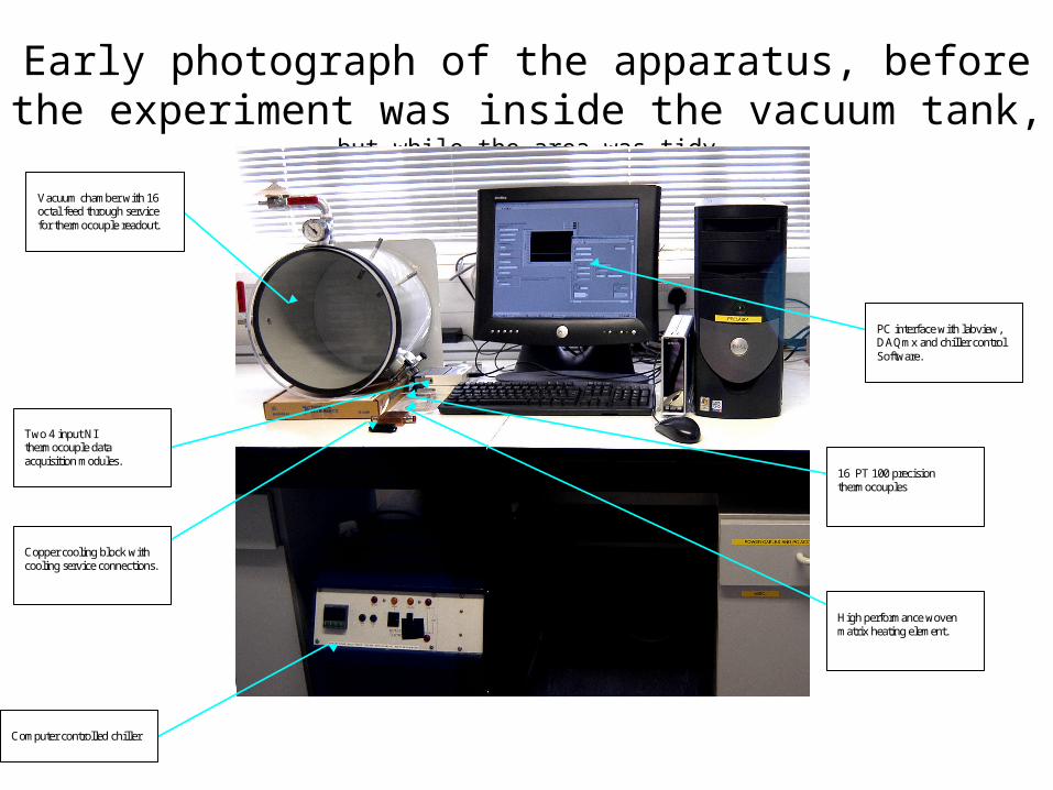
Early photograph of the apparatus, before the experiment was inside the vacuum tank, but while the area was tidy
Vacuum chamber with 16 octal feed through service for thermocouple readout.
Copper cooling block with cooling service connections.
Two 4 input NI thermocouple data acquisition modules.
Computer controlled chiller
High performance woven matrix heating element.
PC interface with labview, DAQmx and chiller control Software.
16 PT 100 precision thermocouples

Thermal studies
Plastic insulating supports
DUT
H2O
V,I measured
ElectricalHeaters
Water cooledCu block
Al thermalshield PT100s
RTD1 RTD2 RTD3
Details of the measurement
• Radiation reduction– Radiation shield around the sample– Polystyrene balls filler– Cool outside of tank to Copper block temperature
• Conduction reduction– RTD wire 44SWG Manganin tied to the cooling block– Thermally insulating mounts for apparatus
• Convection reduction– Vacuum tank
• Accuracy– 4 wire temperature sensors and heater– Careful calibration of RTDs against each other (temperature
differences important)
Measurement details
• Sample size– Defined by thermal shield size and vacuum tank– Presently : 10cm x 1 cm– Max length at present : 20cm (limited by vac tank)
• Heater power– Max at present 0.5W– Easy to manage temperatures in the shield and only small
changes in sample temperature– Requires accurate temperature measurements (TPG ΔT = 0.5C)
• Cooling– Use anti-freeze based chiller : -20C minimum temperature– Peltier elements to further reduce temperature

The experiment
• Sample and thermal shield clamped to cold block
• Copper tower to clamp PT100 wires to cold block
• Heaters on sample and shield removed
Pocofoam under test
Thermal shield
Cooling block
PT100 with Manganin wire

Experiment sits inside a vacuum tank to isolate it from the external environment
Vacuum Chamber
Support/Insulation (polystyrene)
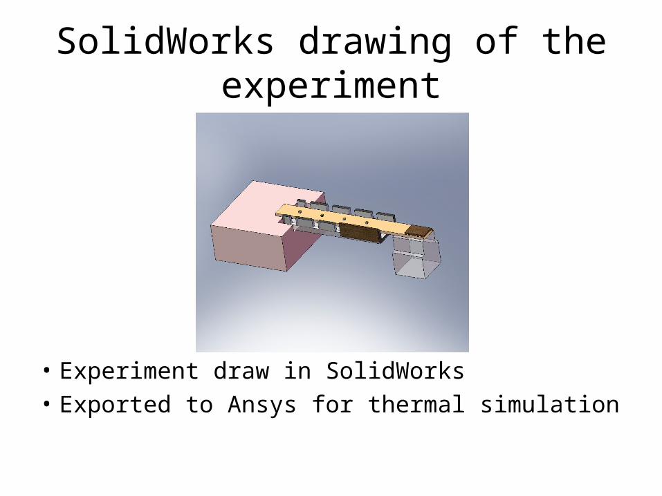
SolidWorks drawing of the experiment
• Experiment draw in SolidWorks
• Exported to Ansys for thermal simulation
Simulation
• Ansys FEA simulation performed on the simulation– Radiation losses to the environment included– Conduction losses to the environment included– Convection losses ignored
• Detailed simulation performed for sample of known thermal conductivity– Understand all heat loss paths to reproduce
experimental results– Undesired heat paths removed as much as possible
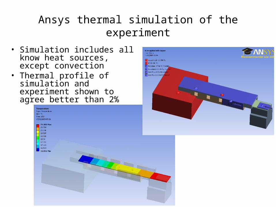
Ansys thermal simulation of the experiment
• Simulation includes all know heat sources, except convection
• Thermal profile of simulation and experiment shown to agree better than 2%
0
0.5
1
1.5
2
2.5
3
3.5
5 10 15 20 25 30 35
Temperature
Len
gth
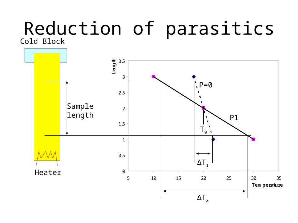
Reduction of parasiticsCold Block
Heater
Samplelength
P=0
P1
T0
ΔT1
ΔT2
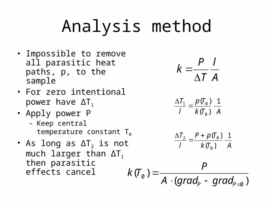
Analysis method
• Impossible to remove all parasitic heat paths, p, to the sample
• For zero intentional power have ΔT1
• Apply power P– Keep central temperature
constant T0
• As long as ΔT2 is not much larger than ΔT1 then parasitic effects cancel
A
l
T
Pk
ATk
Tp
l
T 1
)(
)(
0
01
ATk
TpP
l
T 1
)(
)(
0
02
)()(
00
PP gradgradA
PTk
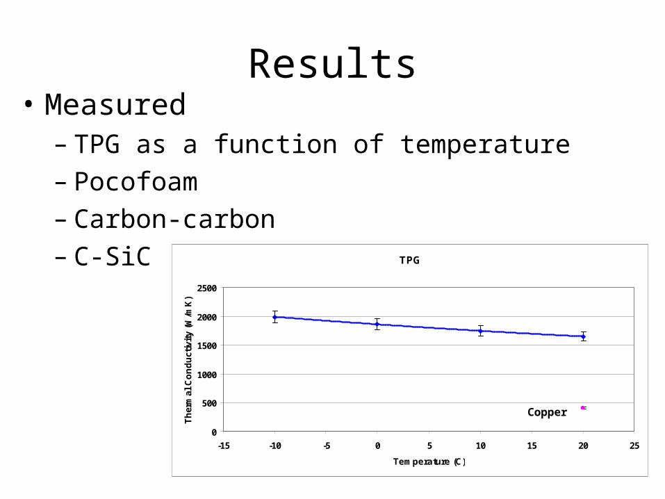
Results• Measured
– TPG as a function of temperature– Pocofoam– Carbon-carbon– C-SiC TPG
0
500
1000
1500
2000
2500
-15 -10 -5 0 5 10 15 20 25
Temperature (C)
Th
erm
al C
on
du
ctiv
ity
(W/m
K)
Copper

Through-plane thermal conductivity measurements
V,I measured
Water cooledCu block
HeatedCu block
PT100s
Plastic thermalinsulation
System in a vacuum and surrounded by polystyrene for thermal insulationDUT size: 1 cm x 1 cm x 100umMeasure thickness with a travelling microscope
DUT
Pressure gaugeLoad cell
Screw, to apply pressure
Vacuum vessel
Future work
• System undergoing an upgrade– Extension of the operating range away from
room temperature (-20C to -50C)– Additional radiation shield around the set-up– Improved vacuum tank (aim 1x10⁻⁶mbar)– Use of Peltier elements to lower temperature– Goal to test to -50C or lower