Embed Size (px)
Citation preview

NREL is a national laboratory of the U.S. Department of Energy, Office of Energy Efficiency and Renewable Energy, operated by the Alliance for Sustainable Energy, LLC.
Thermal Performance and Reliability of Bonded Interfaces
PI: Douglas DeVoto National Renewable Energy Laboratory May 15, 2012
Project ID: APE028
This presentation does not contain any proprietary, confidential, or otherwise restricted information.

2
Overview
Timeline Project Start Date: FY10 Project End Date: FY12 Percent Complete: 80%
Barriers and Targets • Cost • Weight • Performance and Lifetime
Budget Total Project Funding: DOE Share: $1.4M
Funding Received in FY11: $600K Funding for FY12: $425K
Partners • Interactions / Collaborations
• General Motors, Btech, Semikron, Heraeus, Kyocera, Virginia Tech, Oak Ridge National Laboratory (ORNL)
• Project lead: NREL
3
Silicon die
Metalized substrate
Base plate
BIM
Wire/ribbon bonds
Relevance/Objectives
• Excessive temperature (>150°C for silicon [Si] devices) can degrade the performance, life, and reliability of power electronics components
• Interfaces in the package can pose a major bottleneck to heat removal
• Conventional thermal interface materials (TIMs) do not meet thermal performance and reliability targets—the industry trend is towards bonded interface materials (BIMs)
• Bonded interfaces, such as solder, degrade at higher temperatures and are prone to thermomechanical failure under large temperature cycling
100
110
120
130
140
150
160
0 2 4 6 8 10 12 Distance across the package (mm)
Tem
pera
ture
(°C)
100 mm2K/W 20 mm2K/W 10 mm2K/W 5 mm2K/W
IGBT location
Baseplate back side Heat sink base Glycol-water
temperature
ΔTTIM
Credit: Douglas DeVoto, NREL

4
Relevance/Objectives
• Overall Objective – Investigate the reliability of emerging BIMs (such as silver sinters, lead-free solders, and
thermoplastics with embedded carbon fibers) for power electronics applications to meet the thermal performance target of 5 mm2K/W
– Identify failure modes in emerging BIMs, experimentally characterize their life under known conditions, and develop lifetime estimation models
• Address Targets – High-performance, reliable, low-cost bonded interfaces enable:
o Compact, light-weight, low-cost packaging o High-temperature coolant and/or air cooling
• Uniqueness and Impacts
– Thermal performance and reliability of emerging sintered materials and thermoplastics in large-area attach will be characterized.

5
Milestones
Date Milestone or Go/No-Go Decision
June 2011 Evaluated bond quality of initial samples using nondestructive acoustic imagery (C-SAM). Aluminum nitride (AlN) delamination failures on many samples initiated change to silicon nitride (Si3N4) substrates.
October 2011 Completed initial finite element analysis (FEA) modeling to determine plastic work/strain energy density in lead-based solder BIM while under cycling.
December 2011 Received new Si3N4 substrates and tested for delamination under accelerated temperature cycling profile. New substrates meet reliability requirements for BIM testing.
January 2012 Synthesized second set of samples using revised substrates. Btech HM-2 bonded at NREL and sintered silver bonded at Semikron.
May 2012 Complete double lap shear testing of lead-based solder samples and use stress/strain data to revise viscoplastic properties needed for FEA.
September 2012 Complete experimental temperature cycling of samples to 2,000 cycles or until failure. Develop strain energy density versus cycles-to-failure models for lead-based and lead-free solders.

6
Approach/Strategy
BIM Mechanical Characterization
Sample Synthesis
Reliability Calculation
Thermal Testing/ Characterization
Synthesis of samples using stencil printer and hot press
Cycling of samples in a
thermal shock chamber
Characterization of samples via steady-state thermal resistance tester, hipot tester, C-SAM, and
X-ray imaging
Shear tests to extract mechanical characteristics
of BIMs
Number of cycles to crack
initiation/ delamination
Fatigue life prediction
Strain energy density per cycle
Extraction of viscoplastic parameters
Experimental Approach Numerical Approach - FEA/Calculations

7
BIM Finite Element Modeling
-80
-40
0
40
80
120
160
0 2000 4000 6000 8000 10000 12000 14000
Tem
pera
ture
(°C)
Time (s)
Temperature Cycling Profile • Temperature cycling parameters: – Maximum temperature = 150°C
– Minimum temperature = -40°C
– Ramp rate = 10°C
/minute
– Dwell time = 10 minutes • Viscoplastic material model applied to solder
layer • Temperature-dependent elastic material
properties incorporated for baseplate and substrate
Baseplate
Solder layer
Substrate
Quarter Symmetry Model

8
BIM Finite Element Modeling
• Accumulated plastic work per volume distribution in the bonded joint region (63Sn-37Pb solder)
• Plastic work higher in the corner regions—location where failures are likely to originate
• Plastic work/strain energy density versus cycles-to-failure correlation to be obtained for lead-based and lead-free solders
Solder Layer Bottom Surface (Quarter Symmetry Model) Solder Layer Corner View
0.00E+00
2.00E+06
4.00E+06
6.00E+06
8.00E+06
1.00E+07
1.20E+07
0 5000 10000 15000 20000 25000
Plas
tic W
ork
(Pa)
Time (s)
Plastic Work Per Volume

9
BIM Mechanical Characterization • Strain prediction of solder material is dependent on stress,
temperature, and time – A high enough stress will cause the material to plastically deform – Solder has a tendency to creep at room temperature; this increases
as operating (absolute) temperature approaches the melting temperature
– Creep, or time-dependent plasticity, occurs when a material’s absolute temperature is greater than one-half of its melting temperature
• Viscoplasticity models combine plasticity and creep deformations into one equation to properly define solder in FEA
Primary Creep
Secondary Creep
Tertiary Creep
Rupture
Time
Stra
in
Initial Strain (elastic + plastic)
Creep Curve
Strain
Stre
ss
Stress-Strain Curve
Elastic Behavior
Plastic Behavior
Permanent Set

10
BIM Mechanical Characterization Double-Lap Shear Fixture and
Sample
0
20
40
60
80
0 0.02 0.04 0.06
Stre
ss, M
Pa
Strain
Example Stress/Strain Data at Constant Strain Rate (0.02s-1)
-40°C
-20°C
40°C
80°C
Credit: Douglas DeVoto, NREL
• A double-lap shear testing fixture was designed for solder BIM specimens
– Sample testing at various strain rates and temperatures generates the needed data to characterize the viscoplastic nature of solder
• A script was developed to derive viscoplastic parameters from strain rate test data
– This will allow the behavior of new solder materials to be modeled in FEA simulations

11
Sample Assembly • Five samples of each BIM (between substrate/copper base
plate) were synthesized for testing and included: – Silver coating on the substrate and base plate – Substrate based on a Si3N4 active metal bonding process – An interface between 50.8-mm x 50.8-mm footprint
• Samples followed manufacturer-specified reflow profiles, and bonds were inspected for quality
Sample Assembly
Credit: Douglas DeVoto, NREL
Bond Material Type Name Comments
Solder Kester Sn63Pb37 Baseline (lead-based solder)
Solder Henkel Innolot LF318 Lead-free solder
Sintered Silver Heraeus LTS043 Based on micron-size silver particles
Sintered Silver nanoTach® Based on nanoscale silver particles
Adhesive Btech HM-2 Thermoplastic (polyamide) film with embedded carbon fibers

12
Thermal Cycling • Cycle Profile
– Thermal extremes from -40°C to 150°C – Ramp rate of 5°C/minute, with a
dwell/soak time of 10 minutes – Adherence to JEDEC* Standard 22-A104D
for temperature cycling
Shock Chamber
Credit: Douglas DeVoto, NREL -50
0
50
100
150
200
0:00 0:30 1:00 1:30 2:00 2:30 3:00
Tem
pera
ture
(°C)
Time (h:mm)
Shock Chamber Testing
Sample Profile
Temperature Profile
* JEDEC: Joint Electron Device Engineering Council

13
Thermally Conductive Adhesive Film • Btech HM-2 (Carbon Fibers within Polymer
Matrix) – Bonding
o HM-2 was cut to the base plate dimensions. The sample assembly was placed in the hot press and raised to 195°C, then ~1 MPa (150 psi) of pressure was applied.
– Reliability Results o C-SAM images show less contrast with thermoplastics, but
uniform bonds were obtained. o After 200 cycles, the bonded interface remained defect-free.
Credit: Douglas DeVoto, NREL (all photos)
0 Cycles
100 Cycles
Cold Plate
Sample Hot Plates
Cold Plate
Screw Jack
Hot Press
100 Cycles 200 Cycles

14
Silver Sinter • Semikron Silver Sinter
– Bonding o Corners of the Si3N4 were rounded off to match the 2-mm
radius of copper layers. The sample assembly was placed in a hot press and raised to its processing temperature, then pressure was applied.
o Independent compression testing of substrates at ORNL showed cracking of substrates required between 30 MPa to 50 MPa of pressure.
– Reliability Results o Uniform bonds were obtained. o After 200 cycles, the bonded interface remained defect-free.
Credit: Douglas DeVoto, NREL (all photos)
0 Cycles
100 Cycles
100 Cycles 200 Cycles

15
Collaboration and Coordination
• Partners – General Motors (Industry): technical guidance – Virginia Tech (Academic): collaboration on synthesis of samples using
silver sintered material – ORNL (Federal): collaboration to determine maximum pressure that
Si3N4 substrates could withstand – Btech (Industry): collaboration on optimizing thermoplastic BIM for
large area attach – Semikron (Industry): provided bonded samples to NREL using
company’s silver sintering process – Heraeus (Industry): collaboration on using low pressure silver
sintered materials before products are commercially available – Kyocera (Industry): provided insight on Si3N4 substrate bonding
process and advantages over AlN substrates
16
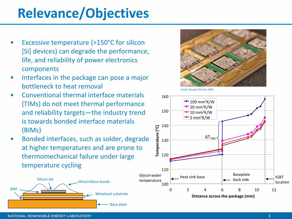
Proposed Future Work (FY12)
• Derive viscoplastic parameters for lead-based and lead-free solders from double-lap shear test experiments
• Expand strain energy density versus cycles-to-failure models to lead-free solders
• Complete 2,000 thermal cycles on all selected materials using Si3N4 based substrates
• Report on reliability of each BIM under specified accelerated test conditions

17
Summary • DOE Mission Support
– BIMs are a key enabling technology for compact, light-weight, low-cost, reliable packaging and for high-temperature coolant and air-cooling technical pathways.
• Approach – Synthesis of various joints between substrates and baseplate, thermal
shock/temperature cycling, high-potential test and joint inspection (C-SAM), and strain energy density versus cycles-to-failure models.
• Accomplishments – Synthesized a number of bonded interfaces between substrate and copper
baseplate based on different BIM technologies
o Lead-based and lead-free solder, sintered silver (micron-size and nanosilver), thermoplastic.
– Initiated FEA for solder bonded interface geometries.

18
Summary • Collaborations
– General Motors, Virginia Tech, ORNL, Btech, Semikron, Heraeus, Kyocera
• Future Work – Derive viscoplastic parameters for lead-based and lead-free solders from
double-lap shear test experiments – Expand strain energy density versus cycles-to-failure models to lead-free
solders – Complete 2,000 thermal cycles on all selected materials using Si3N4 based
substrates – Report on reliability of each BIM under specified accelerated test conditions

For more information contact:
Principal Investigator Douglas DeVoto [email protected] Phone: (303)-275-4256 APEEM Task Leader
Sreekant Narumanchi [email protected] Phone: (303)-275-4062
Acknowledgments:
Susan Rogers and Steven Boyd, U.S. Department of Energy Team Members:
Mark Mihalic Paul Paret