Embed Size (px)
Citation preview
Periodicals of Engineering and Natural Sciences ISSN 2303-4521
Vol. 9, No. 2, April 2021, pp.784-798
784
Thermal performance of double-layer porous copper strips mounted as
hollow cylinders
Ahmed AAG. Alrubaiya, *, Basim A.R. Al-Bakrib and Radwan M. Aljuhashyc
a Department of Materials Engineering, Diyala University, Baquba, Diyala Province, Iraq b Department of Aeronautical Engineering, University of Baghdad, Aljadriya, Baghdad, Iraq
c Department of Mechanical Engineering, Wasit University, Kut, Wasit, Iraq
ABSTRACT
The thermal performance of thin double-layer porous copper strips was experimentally examined. To
fabricate double-layer porous copper strips the lost carbonate sintering procedure was employed. The
suitability of these materials for applications of heat sink was systematically investigated. Then, the thermal
properties of an external heat transfer facility, which operates under a forced heat convection process using
air as a coolant, were assessed. In this case, a cylindrical heating system was chosen to be used with the air
passing across the samples at mass rates of 0.1- 0.5 kg/s. The temperatures of the air at the inlet and outlet in
addition to the surface temperature of the system were monitored and used to determine the heat transfer
performance. The results showed that both the porosity and roughness in a surface of a material could play
an essential role in such type of material in enhancing heat transfer at a surface of the system. With high
porosity and surface roughness of up to 82% and Ra ≤ 1.21 mm, respectively, the sample achieved a thermal
transmittance 57% higher than that of a reference smooth copper sheet under the same Reynolds number.
Finally, the heat transmittance of the examined porous sheets in the current research increased with the bulk
porosity and surface roughness.
Keywords: Porosity; Copper sheets; Tape casting; Roughness surface heat transfer; heat
sink; heat exchanger.
Corresponding Author:
Ahmed AAG. Alrubaiy Department of Materials Engineering Diyala University, Baquba, Diyala Province, Iraq
1. Introduction
Very thin and porous layers of a wide surface area of a copper material to the thickness ratio are potentially
attractive. This could be achieved for the thermal management in space-limited devices where better
performance of heat transfer within confined dimensions is highly required. Currently, thermal aspects have
been becoming increasingly important in order to ensure high performance device, when electronics has become
more compact and slimmer than before. [1], [2]. A type of porous metals, which is well-known open-celled,
with small thicknesses and high energy is likely to be suitable for the current application. However, other types
of metals, which are made from copper in porous form, can highly conduct heat extremely. Therefore, porous
copper metals have been considered in manufacturing of the body of heat exchangers and heat sinks [3-6].
Performance of heat transfer of different forms of porous material has been studied and reported, from lotus–
structure types [7], [8], and [9], to open-celled structure types [4], [5], and [10]– [13]. This work has
demonstrated that the performance of heat transfer of a porous material heat exchanger is mainly influenced by
the porosity/density of the porous medium and the morphology of the pores and morphology of the cell walls.
The heat transfer process through a porous material is controlled by conductive heat transfer within the solid,
with a lesser contribution from radiative heat transfer between the cell walls. Heat transport from a heat
exchanger to the flowing fluid is dominated by convective heat transfer. Therefore, the overall heat transferred
PEN Vol. 9, No. 2, April 2021, pp.784- 798
785
from the heat source by a porous metal heat exchanger depends on the mesostructure. The arrangement of
porosity is explained as the mesos
tructure, which is also defined as the structural level between the metallic microstructure and the overall form
of the component. The key factors that affect the volumetric porosity and pore morphology are in turn dependent
on the manufacturing technology and process conditions adopted in producing the sample [3] and [14]– [17].
These may not be the only factors; surface roughness has also been shown to have a huge effect on the
performance heat transfer of heat sinks [18]– [20], although this has not been specifically explored in porous
metals.
In the current study, a thickness down to 1.4 mm of porous sheets of copper was manufactured and
investigated for the performance of heat transfer. Moreover, the current copper samples were formed by lost
carbonate sintering for the casting of copper strips [21]. This process paves the way to control both thickness
and porosity of the component. The strips consisted of two porous layers with porosity in the range of 50 - 82%
substrates of 0.125 mm thickness. This design was used to provide a solid backing that could be placed in
contact with a component requiring cooling, and to have this backing intimately connected to a porous region
within which heat transfer would take place. The thermal properties of the system will be assessed by forced
heat convection using a coolant fluid (air). Temperatures of the system (fluid and structure) will be monitored
by employing an open-circuit instrument of heat transfer. Additionally, smooth surfaces and non-porous copper
sheets will be thoroughly investigated under similar boundary conditions to that of the provided reference case
study.
2. Experimental approach
2.1 Sample preparation
Samples with double porous layers were produced by the lost carbonate sintering process. For cast copper
stripes, the raw materials were dendritic powder copper Cu, as the base metal and potassium carbonate K2CO3
as the leachable space holder. The porosity can be adjusted by adding K2CO3 at percentage of 10 – 50 wt, as
shown in Table 1. The powders were mixed with organic binders into a homogenous slurry. The slurry was
tape-cast into thin layers on top of a 0.125 mm thick copper substrate in two ways, described below as two main
processing paths A and B.
Process path A: A slurry was directly tape cast on adense copper of 0.125 mm thickness controlled using a
built-in stationary blade. Under a vacuum environment conditions, the samples were obtained through debinding
at 450°C and sintering at 890°C. The space holder was detached by dissolution in water at room temperature,
and the porous copper sheets produced are shown in Figure 1. These samples were observed to have relatively
low porosities visible from the surface.
Process path B: The path was developed to attempt to increase the porosity. In contrast to process path A, firstly,
the slurry was a tape cast onto a non-stick silicone tape (Polyester Mylar Film), then inverted and placed onto
the dense copper substrate of 0.125 mm foil. The purpose of this was to reverse the distribution of the carbonate
space holder particles. It was debound and sintered under the same conditions as above. The porous samples
produced by this process were observed to gain higher surface porosity compared to process path A and slightly
higher volumetric porosity. The samples were produced by this path, as shown in Figure 2.
Table 1. Weight ratios of K2CO3 and Cu used during processing of the samples
Process path Amount of Carbonate
(wt.%)
0P.Cu 20P.Cu 30P.Cu 40P.Cu 50P.Cu
A 0 20 30 40 50
B 0 20 30 40 50
The number refers to the added weight per cent K2CO3, while the middle term (P.Cu) refers to porous copper.

PEN Vol. 9, No. 2, April 2021, pp.784- 798
786
0P.Cu 20P.Cu 30P.Cu 40P.Cu 50P.Cu
Figure 1. Strips of porous copper formed by the process path A at volumetric porosity ranges from 51% -
81%.
0P.Cu 20P.Cu 30P.Cu 40P.Cu 50P.Cu
Figure 2. Strips of porous copper formed by the process path B at volumetric porosity ranges from 51% - 82%
Two sets of samples were investigated. The surface and volumetric porosity of the first set of path A ranges
from 28% - 61% and 50% -81%, respectively. The second set of path B had surface and bulk porosity that
ranged from 29% - 74% and 51% - 82% respectively.
Sheet metal cutters were used to cut the sample into the required size and shape. Each sample is a double-layer
thin sheet with the following dimensions of 160 mm × 100 mm× ~1.4 mm and mounted as a hollow cylinder.
During processing, the sample surface developed a degree of roughness, which increased with higher additions
of the carbonate space holder, and with increasing porosity.
2.2 Porosity and surface roughness of the samples
Bulk porosity: the volumetric porosity (bulk) of the porous copper sheets can be obtained by using (Accupyc
1340, Micromeritics). It is simply a helium pycnometer that depends on the following equation:

PEN Vol. 9, No. 2, April 2021, pp.784- 798
787
𝜺 = (𝟏 −𝝆𝒂
𝝆𝒕) × 𝟏𝟎𝟎 (1)
where 𝝆𝒂 refers to the apparent density, which is obtained by dividing the mass at 0.0001kg by the volume. The
volume can be gained using the Vernier caliper to measure dimensions. The symbol 𝝆𝒕 represents the true
density of the porous surfaces that can be acquired using the helium pycnometer.
Surface porosity: The porosity of the porous copper strips was measured with the aid of actual size image
analysis. Sample photographs were taken under medium to low light conditions. The reason for this was to
clearly demonstrate the two different surface areas (pores and continuous) for micropores and macropores, for
the sample’s images. Micropores can be evaluated by SEM micrographs. The ImageJ method [22] and [23]
were used for calibrating and processing the sample photographs. Any unidentified pores that appeared as dark
areas on the surface were considered as surface defects, and they were removed manually. The processing was
conducted in the ImageJ2 (Fiji) analysis program to calculate the cross-sectional area for each pore and their
axes. The frequency of samples and K2CO3 particles can be analyzed by using the Prism 9 for Macintosh OS
X 10.12, GraphPad Software.
Firstly, images, which were captured by a modern technology camera (Nikon -D5200 model) built-in with 24-
52 mm lens (AF-S 16-35mm f/4 G), was analyzed to study the surface roughness of the current work sheets.
Secondly, Fiji software was utilized to sketch the surface shapes of samples. Then, the last step was performed
the statistical analysis of these profiles by using Microsoft Excel spreadsheets.
Table 2: Results of porosity, surface area, and roughness and peak value per centimeter of porous copper strips
produced and investigated in the current study for the samples of paths A and B.
Processing Samples Roughness Peaks Per Bulk Surface Micropores Macropores
Path value, Ra Centimeter, Porosity, porosity, Surface Surface
m ɛ (%) PSurf, (%) Area Area
(cm2/cm
3) (cm
2/cm
3)
0P.Cu 0.031 - 50.7 28.6 2616 179
20P.Cu 0.411 3.43 70 39.7 1693 442
Path A
30P.Cu 0.884 4.29 75.2 45.1 1412 553
40P.Cu 0.960 4.57 78.4 49.6 1217 641
50P.Cu 1.209 4.86 80.5 60.5 870 833
20P.Cu 0.559 3.72 73.6 47.6 1212 621
Path B
30P.Cu 0.841 4.29 79.0 54.6 802 799
40P.Cu 0.957 4.57 80.4 62.1 658 920
50P.Cu 1.030 5.43 81.5 73.4 384 1132
The porous in the current samples, which were produced from the path B process, has a high level of surface
and volumetric porosity to those created from the path A, as presented in Table 2. The surface roughness of
both the path A and B sheets are also summarized in Table 2. In addition, strips came from the path A have
higher roughness values and number of peaks per centimeter length, m than those form the path B. Table 2 also
shows the surface area of the porous in the samples considered in the current study. This clearly demonstrates
the contributions of the macropores (large pores, roughly corresponding to the shape and size of particles in the
space holder) and micropores (finer-scale porosity, associated with incomplete densification of the metal
powder) to the total surface area of the sample.

PEN Vol. 9, No. 2, April 2021, pp.784- 798
788
2.3 Quantity of heat measurements 2.3.1 Experimental Setup The suitability of the porosity in copper samples for applications that have heat transfer systems, was studied
by using an open-cycle wind tunnel. Figure 3, shows a schematic diagram of the test facility which was used to
study the samples. The test facility includes two centrifugal fans, hot-wire anemometer (HWA) system, wind
tunnel, micro-foil heat flux sensor, and thermocouples-type, J, K, and T. Computers can run PicoLog software
which acquires data. So, the function of each section of the test facility are going to be explained in the next
paragraphs.
Figure 3. Schematic diagram of the thermal test facility
The two centrifugal fans, which were set at the exit of the wind tunnel as the air was forcibly introduced into
the air inlet by suction. The graded throttle valves were set at the exit of the tunnel to govern the air volume.
The air velocity was measured using a calibrated hot-wire anemometer (HWA). The wind tunnel consists of a
squire section of 125 mm. A honeycomb mesh was set up behind the test section in order to reduce the bulk
flow that was induced by the centrifugal fans. Moreover, the test section was placed in the middle of the air
tunnel, as seen in Figure 3. Thermocouples of K-type and T-type of up to 100 m was utilized to measure
temperatures of the air at the inlet and outlet and the surface of the samples. These thermocouples can be logged
by using PicoLog software.
The cylindrical heating system CHS, as shown in Figure 5, was specially manufactured to fit porous sheets.
This system was made of an aluminum metal cylinder of 50 mm diameter, polyether ether ketone PEEK as
insulator of also 50 mm diameter and a 400W cylindrical heating cartridge of 10 mm diameter, which is taken
by a J-type thermocouple. The heating element was fixed at the center of the metal cylinder in order to make
the homogenized heat passes in the radial direction.
The range of the velocity was between 5 m/s to 21 m/s that used to test the samples. Moreover, an RS PRO
IDM66RT handheld digital multimeter, with RS calibration (AC Voltage Accuracy ±1% + 5 Digits) was
employed to measure the power supplied to the heating element, the cartridge heater.
PEN Vol. 9, No. 2, April 2021, pp.784- 798
789
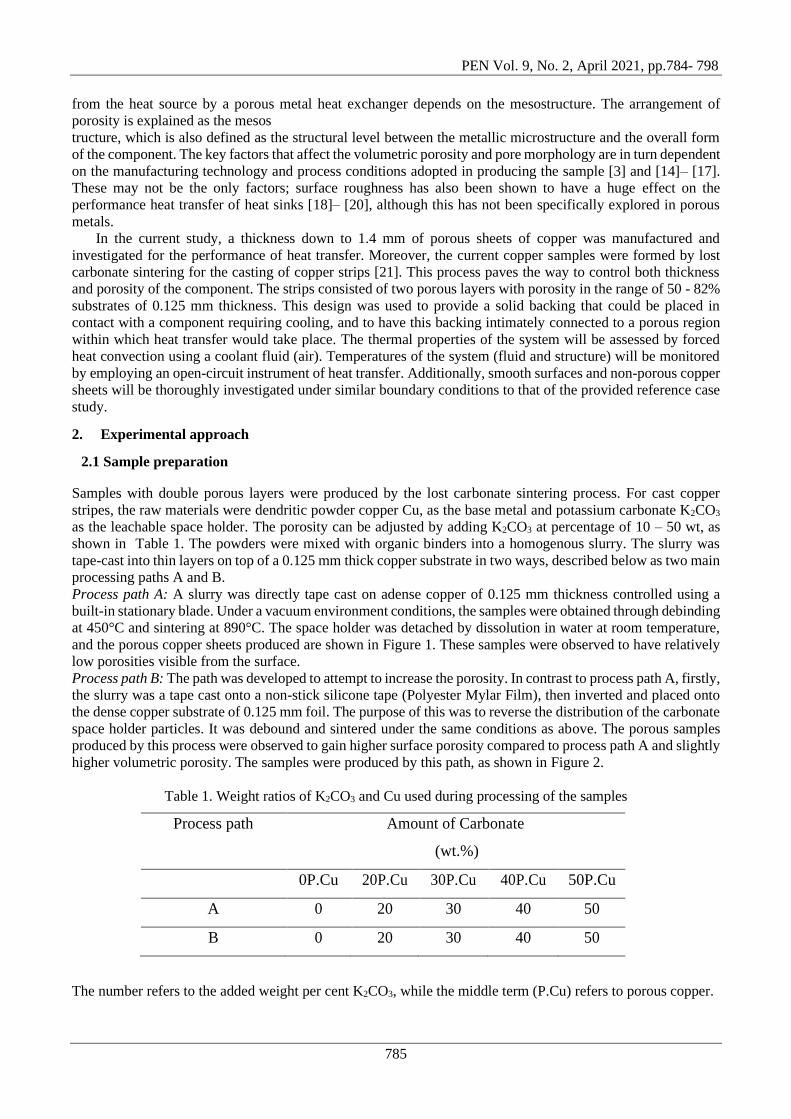
Figure 4. Schematic diagram of sample positioning and heating system relative to air duct and flow direction
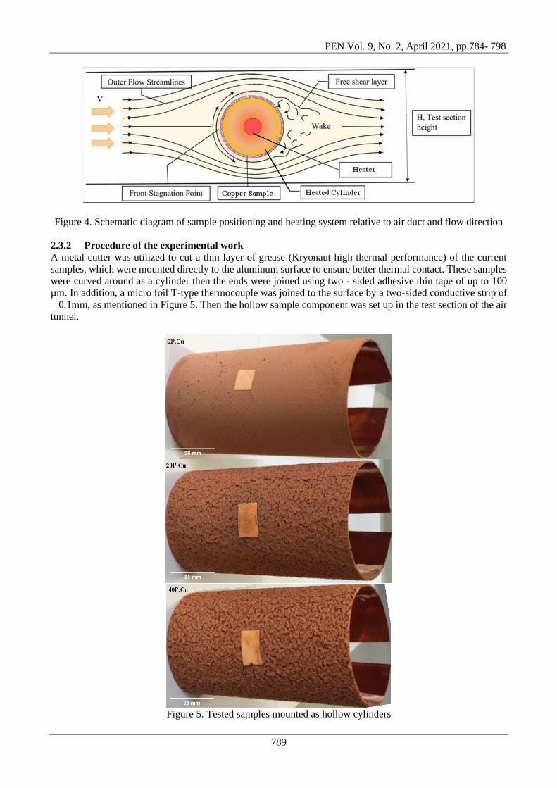
2.3.2 Procedure of the experimental work
A metal cutter was utilized to cut a thin layer of grease (Kryonaut high thermal performance) of the current
samples, which were mounted directly to the aluminum surface to ensure better thermal contact. These samples
were curved around as a cylinder then the ends were joined using two - sided adhesive thin tape of up to 100
µm. In addition, a micro foil T-type thermocouple was joined to the surface by a two-sided conductive strip of
0.1mm, as mentioned in Figure 5. Then the hollow sample component was set up in the test section of the air
tunnel.
Figure 5. Tested samples mounted as hollow cylinders
PEN Vol. 9, No. 2, April 2021, pp.784- 798
790
When the heating system was on, the majority of the thermal energy moved through a tested sample into the
atmosphere by the convection way of heat transfer 𝖰conv. Whereas, a small rate of energy passed to the barriers
of the air tunnel by the conduction way Qcond and radiation way 𝖰rad. Approximately 2% of the energy was
found to be lost by conduction to the PEEK guards and was neglected from the analysis
𝖰rad = σBϵA(Ts4 − Tt
4) (2)
𝖰conv = hA(T𝑠 − T𝑎) = T𝑟(T𝑠 − T𝑎) (3)
𝖰conv = P − 𝖰rad − 𝖰cond = P − σBϵA(Ts4 − Tt
4) (4)
Where the constant number of Stefan-Boltzmann is represented by 𝜎𝐵 is 5.67 × 10⁻⁸ W m2k2⁄ , 𝜖 is the
emissivity of the surface of the sample about 0.6 [25], Ts is the temperature on the surface of the sample, and Tt
is the temperature of the air tunnel wall. Also, Tr is the thermal transmittance in W/K and the convectional heat
transfer coefficient h W m2⁄ k was found as follows:
Tr = Qconv (Ts − Ta)⁄ = [P − σBεA(Ts4 − Tt
4)] (Ts − Ta)⁄ , (5)
h = 𝖰conv A(Ts − Ta)⁄ = [P − σBεA(Ts4 − Tt
4)] A(Ts − Ta)⁄ , (6)
where Ta is the flowing air temperature Ta = (Tin + T𝑜𝑢𝑡) 2⁄ . The Reynolds number can be expressed by the
air velocity sucked inside the tunnel:
ReD = uD ν⁄ , (7)
where the letter D refers to the tested cylinder diameter which equals 50mm, 𝜈 =1.534 × 10⁻⁵ m2/s at Ta =23 C0
is the air kinematic viscosity, which varies with the ambient temperature. Moreover, the average heat transfer
coefficient is obtained in convection by the Nu number as follows:
Nu = hD k⁄ , (8)
where, k=2.83 × 10⁻²W/mK is the thermal conductivity of air. Properties of air in the current study, were taken
according to the average temperature value of the film Tf = (Ts + T𝑎) 2⁄ , and also for standard atmospheric
pressure.
3. Results and discussion
The performance of heat transfer quantity from the two paths A and B of the double-layered porous strips were
examined for each sample by calculating the coefficient of thermal transmittance 𝐓𝐫 (W/Ko) and convection
heat transfer 𝐡 (W/m Ko). Furthermore, smooth sheets without porous were verified to gain 𝐡 and 𝐓𝐫 as
reference values.
The first following two plots can declare the experimental data of the performance of porous sheets of path A
with varying porosity and surface roughness. Whereas, the other two plots demonstrate the results of the heat
transfer effectiveness of porosity sheets of path B by varying porosity and surface roughness.
PEN Vol. 9, No. 2, April 2021, pp.784- 798
791
50 55 60 65 70 75 80 85
1.0
1.5
2.0
2.5
3.0
3.5
4.0
4.5
5.0
5.5 Re = 15 * 103
Re = 28 * 103
Re = 42 * 103
Re = 56 * 103
Re = 65 * 103
Tr
(W/k
)
Bulk Porosity, e (%)
0P
.Cu
20P
.Cu
30P
.Cu
40P
.Cu
50P
.Cu
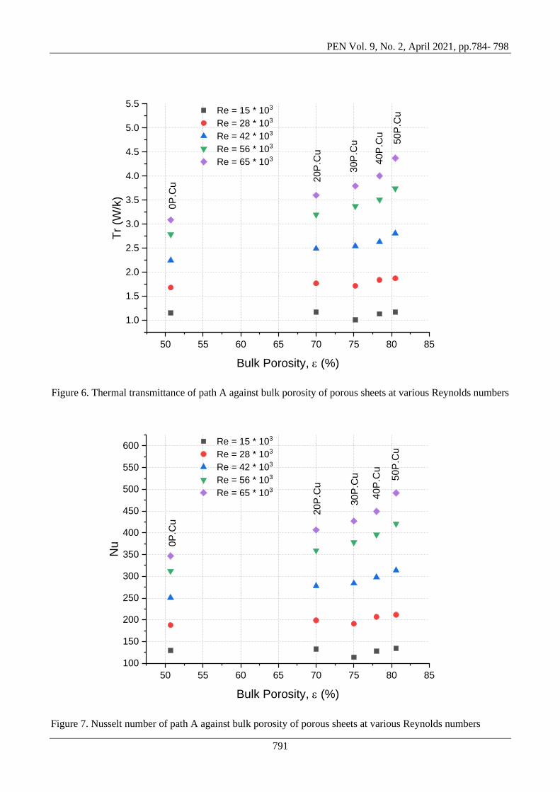
Figure 6. Thermal transmittance of path A against bulk porosity of porous sheets at various Reynolds numbers
50 55 60 65 70 75 80 85
100
150
200
250
300
350
400
450
500
550
600 Re = 15 * 103
Re = 28 * 103
Re = 42 * 103
Re = 56 * 103
Re = 65 * 103
Nu
Bulk Porosity, e (%)
0P
.Cu
20P
.Cu
30P
.Cu
40P
.Cu
50P
.Cu
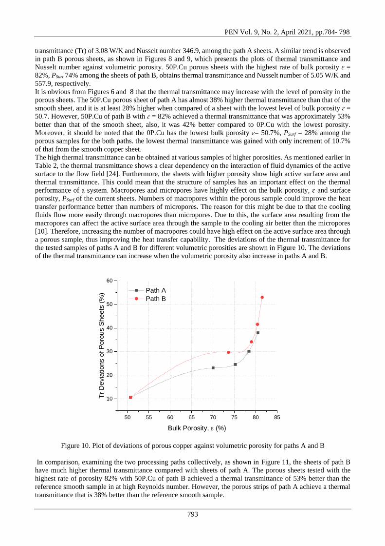
Figure 7. Nusselt number of path A against bulk porosity of porous sheets at various Reynolds numbers

PEN Vol. 9, No. 2, April 2021, pp.784- 798
792
50 55 60 65 70 75 80 85
1.0
1.5
2.0
2.5
3.0
3.5
4.0
4.5
5.0
5.5
6.0 Re = 15 * 103
Re = 28 * 103
Re = 42 * 103
Re = 56 * 103
Re = 65 * 103
Tr
(W/k
)
Bulk Porosity, e (%)
0P
.Cu
20P
.Cu
30P
.Cu
40P
.Cu
50P
.Cu
Figure 8. Thermal transmittance of path B against bulk porosity of porous sheets at various Reynolds numbers
50 55 60 65 70 75 80 85
100
150
200
250
300
350
400
450
500
550
600
650 Re = 15 * 103
Re = 28 * 103
Re = 42 * 103
Re = 56 * 103
Re = 65 * 103
Nu
Bulk Porosity, e (%)
0P
.Cu
20P
.Cu
30P
.Cu
40P
.Cu
50P
.Cu
Figure 9. Nusselt number of path B against bulk porosity of porous sheets at various Reynolds numbers
Figure 6 shows the results of thermal transmittance for copper samples of path A plotted against the volumetric
porosity at varying dimensionless Reynolds numbers. Figure 7 displays plots of the dimensionless Nusselt
number against volumetric porosity at varying dimensionless Reynolds numbers for porous copper sheets of
Path A. At lower Reynolds number regimes, a small change in the thermal transmittance and Nusselt number is
achieved across a range of investigated porosities. At higher Reynolds number regimes, the change in the
thermal transmittance and Nusselt number is clearer against porosity. 50P.Cu, which has the highest level of
bulk porosity ɛ = 81%, PSurt = 60% among the path A sheets, achieves thermal transmittance up to 4.37 W/K
and Nusselt number 491.7. However, 0P.Cu, which has the lowest level of porosity, obtains the lowest thermal
PEN Vol. 9, No. 2, April 2021, pp.784- 798
793
transmittance (Tr) of 3.08 W/K and Nusselt number 346.9, among the path A sheets. A similar trend is observed
in path B porous sheets, as shown in Figures 8 and 9, which presents the plots of thermal transmittance and
Nusselt number against volumetric porosity. 50P.Cu porous sheets with the highest rate of bulk porosity ɛ =
82%, PSurt 74% among the sheets of path B, obtains thermal transmittance and Nusselt number of 5.05 W/K and
557.9, respectively.
It is obvious from Figures 6 and 8 that the thermal transmittance may increase with the level of porosity in the
porous sheets. The 50P.Cu porous sheet of path A has almost 38% higher thermal transmittance than that of the
smooth sheet, and it is at least 28% higher when compared of a sheet with the lowest level of bulk porosity ɛ =
50.7. However, 50P.Cu of path B with ɛ = 82% achieved a thermal transmittance that was approximately 53%
better than that of the smooth sheet, also, it was 42% better compared to 0P.Cu with the lowest porosity.
Moreover, it should be noted that the 0P.Cu has the lowest bulk porosity ɛ= 50.7%, PSurf = 28% among the
porous samples for the both paths. the lowest thermal transmittance was gained with only increment of 10.7%
of that from the smooth copper sheet.
The high thermal transmittance can be obtained at various samples of higher porosities. As mentioned earlier in
Table 2, the thermal transmittance shows a clear dependency on the interaction of fluid dynamics of the active
surface to the flow field [24]. Furthermore, the sheets with higher porosity show high active surface area and
thermal transmittance. This could mean that the structure of samples has an important effect on the thermal
performance of a system. Macropores and micropores have highly effect on the bulk porosity, ɛ and surface
porosity, PSurf of the current sheets. Numbers of macropores within the porous sample could improve the heat
transfer performance better than numbers of micropores. The reason for this might be due to that the cooling
fluids flow more easily through macropores than micropores. Due to this, the surface area resulting from the
macropores can affect the active surface area through the sample to the cooling air better than the micropores
[10]. Therefore, increasing the number of macropores could have high effect on the active surface area through
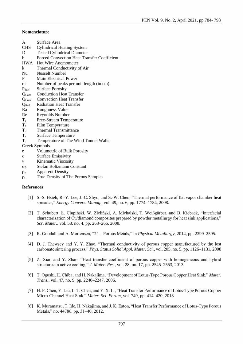
a porous sample, thus improving the heat transfer capability. The deviations of the thermal transmittance for
the tested samples of paths A and B for different volumetric porosities are shown in Figure 10. The deviations
of the thermal transmittance can increase when the volumetric porosity also increase in paths A and B.
50 55 60 65 70 75 80 85
10
20
30
40
50
60
Tr
De
via
tio
ns o
f P
oro
us S
he
ets
(%
)
Bulk Porosity, e (%)
Path A
Path B
Figure 10. Plot of deviations of porous copper against volumetric porosity for paths A and B
In comparison, examining the two processing paths collectively, as shown in Figure 11, the sheets of path B
have much higher thermal transmittance compared with sheets of path A. The porous sheets tested with the
highest rate of porosity 82% with 50P.Cu of path B achieved a thermal transmittance of 53% better than the
reference smooth sample in at high Reynolds number. However, the porous strips of path A achieve a thermal
transmittance that is 38% better than the reference smooth sample.

PEN Vol. 9, No. 2, April 2021, pp.784- 798
794
The high porosities samples have wide active surface areas therefore they are estimated to achieve high thermal
transmittance specially at high Reynolds numbers. Figure 6 and Figure 8 show the thermal transmittance of
porous strips which it increases with an increase in porosity at high Reynolds numbers. The highly porous strips
seem permeable to the cooling fluid, which is significant for the process of heat transfer. Moreover, porous
strips could make the samples rougher than without them.
The roughness of the surface of the porous copper sheets was studied, as seen from Table 2. The porous sheets
of path A, 0P.Cu demonstrates the lowest value of arithmetic average roughness, Ra = 0.03 mm. Nevertheless,
the 20P.Cu of path A shows Ra and number of peaks per centimeter length, m of 0.411 mm & 3.4 peak per
centimeter, respectively. Additionally, 30P.Cu & 40P.Cu of path A could achieve Roughness of 0.88 mm &
0.96 mm and m of 4.3 & 4.6 peak per centimeter, respectively. The last sheet of 50P.Cu of path A declares an
Ra of 1.2 mm and m of 4.86 peak per centimeter. Porous sheets of path B shows high similarity to the path A
except the 50P.Cu of path B that records Ra and m of 1.0 mm and 5.4 peak/cm, respectively.
50 55 60 65 70 75 80 85
2.5
3.0
3.5
4.0
4.5
5.0
Tr
(W/k
)
Bulk Porosity, e (%)
Path A
Path B
Roughened sheet
Smooth sheet
Figure 11. Comparison of the thermal transmittance of paths A and B against volumetric porosity at high
Reynolds number of 65*103
Uneven protrusions appear on the structure of the sample surface during the procedure due to the formation of
copper powder. The surface roughness could stay even after removing bumps. The thermal transmittance can
be affected by the produced surface roughness. Firstly, the fluid dynamic connection between the flow field and
surface could be influenced by protrusions on the surface that may enhance convective heat transfer. Secondly,
high thermal transmittance is expected to be gained when the uneven surface increases which could increase the
convective heat transfer. Furthermore, the thermal transmittance could enhance to 1.2% at high Reynolds
number due to roughening the smooth copper strip that could increase the surface area for the sheet., which
marginally recovers the convection way of heat transfer.
Boundary layer conditions might be influenced by pore and pore wall morphology and also roughness of the
surface, so that the convective heat transfer may also affected when it relies on that layer. Differences in the
performance of heat transfer, however, may happen due to the flow manners around the source of heat.
The morphology of the surface of porous strips contents both porous and rough surface. So that the first section
of the air was obliged to pass through the pores of the heat exchanger, while the other section was flown around
the rough surface. The rate of heat transfer was high because of the increasing in surface area and also due to
the existence of protrusions on the surface of the heat exchanger.

PEN Vol. 9, No. 2, April 2021, pp.784- 798
795
0.0 0.2 0.4 0.6 0.8 1.0 1.2 1.4
1.0
1.5
2.0
2.5
3.0
3.5
4.0
4.5
5.0
5.5 Re = 15 * 103
Re = 28 * 103
Re = 42 * 103
Re = 56 * 103
Re = 65 * 103
Tr
(W/k
)
Roughness, Ra (mm)
0P
.Cu 2
0P
.Cu
30P
.Cu
40P
.Cu
50P
.Cu
Figure 12. Experimental data of the performance of heat transfer against the surface roughness of porous
sheets from path A
0.0 0.2 0.4 0.6 0.8 1.0 1.2
1.0
1.5
2.0
2.5
3.0
3.5
4.0
4.5
5.0
5.5 Re = 15 * 103
Re = 28 * 103
Re = 42 * 103
Re = 56 * 103
Re = 65 * 103
Tr
(W/k
)
Roughness, Ra (mm)
0P
.Cu
20P
.Cu
30P
.Cu
40P
.Cu
50P
.Cu
Figure 13. Experimental data of the performance of heat transfer against the surface roughness of porous sheets
from path B
Back to Figure 3 and Figure 4, it can be seen that the CHF faces the cold air flow in the test section. This position
could make the flow direction in prime with the sample which could pass a lot of cooling air into inlet and outlet
of the current sheets, as seen in Figure 14. The rate of heat dissipation from the porous sheets increased through
the boundary layer due to the mentioned position. In addition, the majority of the amount of air in the boundary

PEN Vol. 9, No. 2, April 2021, pp.784- 798
796
layer might flow over the rough surface of the tested samples, whereas the rest of the air could pass through the
pores and channels.
Disturbances, which was due to air flow through the pores in the rough surface, was available in the boundary
layer. As a result, a shrinkage of the boundary layer can be apparent. Moreover, a high rate of heat transfer was
because of the profile of the velocity and temperature. Thin sheets, which were gained from the current work,
could suit the process of improving heat transfer in such a constrained volume to mimic a high blockage ratio.
Figure 14. Diagram demonstrates the airflow in the face of the rough porous sheet
All in all, an increase in thermal transmittance can be seen from the current porous copper sheets. This increment
was also from the increase in the roughness of surface. The porosity in surfaces of the current samples may
enhance the convective heat transfer compared to dimpled surfaces. Furthermore, a noticeable enhancement in
heat transfer can occur even in a reduced volume of a large porous.
4. Conclusion
Double-layer, porous-dense copper sheets of thickness up to 1.4 mm were successfully fabricated by Lost
Carbonate Sintering for casting copper strips, and their heat transfer performance was investigated. Smooth
copper sheets were tested as references. The current study also reveals that porous layers with a bulk porosity
ranges from 51% to 82%, can enhance the thermal transmittance. In path A, the produced porous strip with high
porosity of up to 81% would increase the thermal transmittance by 38% in comparison to the smooth sheet
under the same conditions. In path B, the produced porous sheets gained a thermal transmittance 53% higher
than the smooth sheet. Surface porosity has a direct effect on the permeability of the porous samples, and
therefore, it affects the thermal transmittance. When comparing the two paths, sheets from path B can
accomplish higher thermal transmittance than the strips of path A because of a high porosity about 73.4%
compared to sheets from path A could reach 60.5%. Both high porosities and surface roughness can contribute
negatively or positively to heat transfer. The thermal transmittance increases up to the most porous sample
tested, indicating that even higher porosities may increase performance still further, through there would be an
upper limit encountered where the metal could no longer transport enough flux of heat. The porous strip had a
potential impact on such structures that have thicknesses lower than 1.4 mm. Moreover, the capability of strips
to be deformed all over the curved surfaces was exposed by the current investigation, which are still ongoing,
and this behavior, therefore, testifies their functionality.
Acknowledgements
The authors would like to gratefully acknowledge the Department of Materials Engineering for financial support
through Diyala University.
PEN Vol. 9, No. 2, April 2021, pp.784- 798
797
Nomenclature
A Surface Area
CHS Cylindrical Heating System
D Tested Cylindrical Diameter
h Forced Convection Heat Transfer Coefficient
HWA Hot Wire Anemometer
k Thermal Conductivity of Air
Nu Nusselt Number
P Main Electrical Power
m Number of peaks per unit length (in cm)
PSurf Surface Porosity
QCond Conduction Heat Transfer
QConv Convection Heat Transfer
QRad Radiation Heat Transfer
Ra Roughness Value
Re Reynolds Number
Ta Free-Stream Temperature
Tf Film Temperature
Tr Thermal Transmittance
Ts Surface Temperature
Tt Temperature of The Wind Tunnel Walls
Greek Symbols
ɛ Volumetric of Bulk Porosity
ϵ Surface Emissivity
ν Kinematic Viscosity
σB Stefan Boltzmann Constant
ρa Apparent Density
ρt True Density of The Porous Samples
References
[1] S.-S. Hsieh, R.-Y. Lee, J.-C. Shyu, and S.-W. Chen, “Thermal performance of flat vapor chamber heat
spreader,” Energy Convers. Manag., vol. 49, no. 6, pp. 1774–1784, 2008.
[2] T. Schubert, Ł. Ciupiński, W. Zieliński, A. Michalski, T. Weißgärber, and B. Kieback, “Interfacial
characterization of Cu/diamond composites prepared by powder metallurgy for heat sink applications,”
Scr. Mater., vol. 58, no. 4, pp. 263–266, 2008.
[3] R. Goodall and A. Mortensen, “24 – Porous Metals,” in Physical Metallurgy, 2014, pp. 2399–2595.
[4] D. J. Thewsey and Y. Y. Zhao, “Thermal conductivity of porous copper manufactured by the lost
carbonate sintering process,” Phys. Status Solidi Appl. Mater. Sci., vol. 205, no. 5, pp. 1126–1131, 2008
[5] Z. Xiao and Y. Zhao, “Heat transfer coefficient of porous copper with homogeneous and hybrid
structures in active cooling,” J. Mater. Res., vol. 28, no. 17, pp. 2545–2553, 2013.
[6] T. Ogushi, H. Chiba, and H. Nakajima, “Development of Lotus-Type Porous Copper Heat Sink,” Mater.
Trans., vol. 47, no. 9, pp. 2240–2247, 2006.
[7] H. F. Chen, Y. Liu, L. T. Chen, and Y. X. Li, “Heat Transfer Performance of Lotus-Type Porous Copper
Micro-Channel Heat Sink,” Mater. Sci. Forum, vol. 749, pp. 414–420, 2013.
[8] K. Muramatsu, T. Ide, H. Nakajima, and J. K. Eaton, “Heat Transfer Performance of Lotus-Type Porous
Metals,” no. 44786. pp. 31–40, 2012.
PEN Vol. 9, No. 2, April 2021, pp.784- 798
798
[9] H. Chiba, T. Ogushi, S. Ueno, and H. Nakajima, “Heat Transfer Capacity of Lotus-Type Porous Copper
Heat Sink for Air Cooling,” J. Therm. Sci. Technol., vol. 5, no. 2, pp. 222– 236, 2010.
[10] L. Zhang, D. Mullen, K. Lynn, and Z. Yuyuan, “Heat Transfer Performance of Porous Copper
Fabricated by the Lost Carbonate Sintering Process,” Mater. Res. Soc. Symp. Proc., vol. 1188, 2009.
[11] S. Mancin, C. Zilio, A. Diani, and L. Rossetto, “Experimental air heat transfer and pressure drop through
copper foams,” Exp. Therm. Fluid Sci., vol. 36, pp. 224–232, 2012.
[12] P. M. Kamath, C. Balaji, and S. P. Venkateshan, “Convection heat transfer from aluminum and copper
foams in a vertical channel - An experimental study,” Int. J. Therm. Sci., vol. 64, pp. 1–10, 2013.
[13] G. Tomás, D. Martins, A. Cooper, and G. Bonfait, “Low-temperature thermal conductivity of highly
porous copper,” IOP Conf. Ser. Mater. Sci. Eng., vol. 101, p. 012004, 2015.
[14] G. J. Davies and S. Zhen, “Metallic foams: their production, properties and applications,” J. Mater. Sci.,
vol. 18, no. 7, pp. 1899–1911, 1983.
[15] J. Banhart, “Manufacture, characterisation and application of cellular metals and metal foams,” Prog.
Mater. Sci., vol. 46, no. 6, pp. 559–632, 2001.
[16] B. L. Lefebvre, J. Banhart, and D. C. Dunand, “Porous Metals and Metallic Foams: Current Status and
Recent Developments **,” vol. 10, no. 9, pp. 775–787, 2008.
[17] V. C. Srivastava and K. L. Sahoo, “Processing, stabilization and applications of metallic foams. Art of
science.,” Mater. Sci., vol. 25, no. 3, pp. 733–753, 2007.
[18] H. Hermann, W. Pitschke, and N. Mattern, “Surface Roughness of Porous Materials and Its
Characterization by X-Ray Absorption Measurements,” Phys. status solidi, vol. 132, no. 1, pp. 103–
114, 1992.
[19] G. Kerckhofs, G. Pyka, M. Moesen, S. Van Bael, J. Schrooten, and M. Wevers, “High-Resolution
Microfocus X-Ray Computed Tomography for 3D Surface Roughness Measurements of Additive
Manufactured Porous Materials,” Adv. Eng. Mater., vol. 15, no. 3, pp. 153–158, 2013.
[20] M. Rajczakowska, D. Stefaniuk, and M. Sobótka, “Roughness analysis of the ‘invisible’ surface by
means of X-ray micro-CT,” pp. 1–4.
[21] Y. Y. Zhao, T. Fung, L. P. Zhang, and F. L. Zhang, “Lost carbonate sintering process for manufacturing
metal foams,” Scr. Mater., vol. 52, no. 4, pp. 295–298, 2005.
[22] J. Schindelin et al., “Fiji: an open-source platform for biological-image analysis,” Nat Meth, vol. 9, no.
7. Nature Publishing Group, a division of Macmillan Publishers Limited. All Rights Reserved., pp.
676–682, Jul-2012.
[23] J. Schindelin, C. T. Rueden, M. C. Hiner, and K. W. Eliceiri, “The ImageJ ecosystem: An open platform
for biomedical image analysis,” Mol. Reprod. Dev., vol. 82, no. 7–8, pp. 518– 529, 2015.
[24] L. Ventola, L. Scaltrito, S. Ferrero, G. Maccioni, E. Chiavazzo, and P. Asinari, “Micro-structured rough
surfaces by laser etching for heat transfer enhancement on flush mounted heat sinks,” J. Phys. Conf.
Ser., vol. 525, p. 012017, 2014.
[25] “Versarien.” [Online]. Available: http://www.versarien-technologies.co.uk/. [Accessed: 05-Aug-2018].