Embed Size (px)
Citation preview
THERMAL STRESS ANALYSIS ON HEAVY TRUCK DISC BRAKE ROTOR
BY USING FINITE ELEMENT ANALYSIS (ABAQUS)
RUSELI KIEN
This report is written as a partial fulfillment of terms in achieving the award for
Bachelor of Mechanical Engineering (Thermal-Fluid)
Faculty of Mechanical Engineering
Universiti Teknikal Malaysia Melaka
MAY 2009
ii
‘I approve that i have read this thesis thoroughly and in my opinion, this thesis is has
fulfilled the criteria covering all the aspects of scope and quality and satisfied to be
Awarded for Bachelor of Mechanical Engineering (Thermal-Fluid).’
Signature :……………………
Supervisor I :……………………
Date :...............................
iii
“I hereby admit that this report is all written by me except for the summary and the
article which I have stated the source for each of them.”
Signature :…………………...
Writer : Ruseli Kien
Date :……………………
iv
ACKNOWLEDGEMENTS
First of all, the author would like thank to God for the blessing given that allow
the author being able to finish this report within the time. The author wishes to
express his sincere gratitude to Mr Mohd.Zaid Akop for contributing valuable time,
advice and assistance. Very special thanks are due to the author’s parents for their
understanding, patience and encouragement throughout the course of this study. The
author also would like to thanks to Dr. Abdul Rahim Abu Bakar from Universiti
Teknologi Malaysia and Prof Andrew Day from Bradford University for sharing the
valuable knowledge about finite element analysis technique and the behavior of the
thermal stress analysis on the brake disc rotor. Special thanks to staff of Webb Brake
disc USA manufacturer especially to Mr. Jeremy and also Mr. Charles for the
cooperation given. Thank you to all members of the BCMT student for the
interesting time and the support given. Finally to Mrs. Cornelia, without her never
ending belief and encouragement, this research would never have been completed.
v
ABSTRACT
Braking system is the most important component in all kinds of vehicles.
While braking, most of the kinetic energy is converted into thermal energy and
increase the disc temperature. Problems such as premature wear of brake pads and
thermal cracking of brake discs are attributed to high temperatures. Consequently
controlling the temperature profiles and thermal stresses are critical to proper
functioning of the braking system. This research project consists of thermal stress
analysis on heavy truck brake disc rotor for steady state & transient analysis. The
variation of thickness will cause the thermal stress occur during the friction between
the pad and disc. The dissipated heat transfer during the periodic braking via
conduction, convection and radiation which also affected the thermal distribution of
rotor. To determine the thermal stress analysis of brake disc rotor, transient finite
element techniques are used to characterize the temperature fields of the ventilated
rotor with appropriate thermal boundary conditions. In order to get the stable and
accurate result of element size, time step selection is very important and all these
aspects are discussed in this paper. The findings of this research provide a useful
design tool and improve the brake performance of disc brake system.
vi
ABSTRAK
Sistem pembrekan adalah merupakan komponen terpenting dalam keenderaan.
Sewaktu membrek, hampir kesemua tenaga kinetik ditukarkan kepada tenaga haba
dan meningkatkan suhu cakera brek. Masalah yang sering berlaku adalah seperti
kesan pramatang pelapik brek dan juga tegasan terma yang berlebihan dalam cakera
brek adalah berpunca daripada kesan pemindahan suhu tinggi. Oleh itu adalah
penting untuk mengawal suhu dan kesan tegasan terma untuk sistem pembrekan
berfungsi dengan baik. Projek penyelidikan ini merupakan projek yang melibatkan
analisis tegasan terma ke atas cakera brek bagi kenderaan berat untuk keadaan
mantap serta keadaan berubah dengan masa. Ketebalan yang berbeza-beza akan
menyebabkan proses tegasan haba berlaku semasa geseran di antara pad brek dan
cakera disk. Pemindahan haba semasa pembrekan berkala dipindahkan melalui
konduksi, perolakan dan juga sinaran menjejaskan taburan terma bagi cakera disk.
Untuk menentukan terma analisis tegasan bagi cakera brek, teknik unsur terhingga
digunakan untuk menunjukkan bagaimana tegasan terma itu dipindahkan ke seluruh
permukaan cakera brek kesan daripada peningkatan suhu dengan menggunakan
syarat-syarat sempadan yang sesuai. Untuk mendapatkan hasil keputusan yang tepat,
pemilihan langkah-langkah yang sesuai adalah penting dan segala aspek
mengenainya dibincangkan dalam kajian ini. Berdasarkan hasil daripada penemuan
penyelidikan ini, ianya boleh digunakan sebagai rujukan awal dalam proses
rekabentuk cakera brek yang berongga.
vii
TABLE OF CONTENTS
CHAPTER ITEMS PAGE
TITLE i
DECLARATION iii
ACKNOWLEDGEMENTS iv
ABSTRACT v
ABSTRAK vi
TABLE OF CONTENTS vii
LIST OF FIGURES xi
LIST OF TABLES xiv
NOMENCLATURE xv
CHAPTER I INTRODUCTON
1.1 Background of Research 1
1.2 Objectives of The Study 2
1.3 Scope 2
1.4 Problem of Statement 3
1.5 PSM Structure 4
CHAPTER II LITERATURE REVIEW
2.1 Overview 5
2.2 Introduction of Braking System 6
2.3 History 8
2.4 Air Disc Brake
2.4.1 Introduction 9
2.4.2 How the Brake Functions 10
viii
CHAPTER ITEMS PAGE
2.4.3 Disc Brakes Component 11
2.4.4 Brake Disc Advantage and Disadvantage 18
2.5 Brake Disc Rotor
2.5.1 Introduction 19
2.5.2 Ventilated Brake Discs 20
2.6 Heat Transfer Finite Element Theory
2.6.1 Introduction 21
2.6.2 Conduction 22
2.6.3 Convection 24
2.6.4 Radiation 25
2.6.5 Steady-State Analysis 26
2.6.6 Transient Analysis 27
2.6.7 Accuracy of Properties and Boundary Conditions 28
2.7 Finite Element Analysis
2.7.1 Introduction 29
2.7.2 ABAQUS Software 30
2.7.3 Application 31
2.7.4 Finite Element Modeling 31
2.7.5 Finite Element Analysis Stage 32
2.8 Review of Previous Research 33
CHAPTER III LOAD ANALYSIS
3.1 Overview 34
3.2 Assumption in Heat Input Calculation 36
3.3 Heavy Truck Model
3.3.1 Introduction 37
3.3.2 Dimension 38
3.3.3 Brake Disc Rotor 39
3.3.4 Disc Material 40
3.4 Heat Flux Analysis
3.4.1 Introduction 41
3.4.2 Braking Energy and Braking Power 42
ix
CHAPTER ITEMS PAGE
3.4.3 Heat Flux per Unit Area 46
3.5 Boundary Condition
3.5.1 Introduction 48
3.5.2 Heat Transfer C. (Braking Surface) 48
3.5.3 Heat Transfer C. (U. Inner Ring Surface) 51
3.5.4 Heat Transfer C. (L. Inner Ring Surface) 53
3.5.5 Heat Transfer C. (U. Outer Ring Surface) 55
3.5.6 Heat Transfer C. (Outer Ring Surface) 57
3.5.7 Heat Transfer C. (Inner Vane Passage) 59
CHAPTER IV FINITE ELEMENT MODELLING
4.1 Overview 64
4.2 ABAQUS Software
4.2.1 Introduction 65
4.2.2 Preprocessing (ABAQUS/CAE) 65
4.2.3 Simulation (ABAQUS/CAE) 66
4.2.4 Post processing (ABAQUS/CAE) 66
4.3 Step Analysis
4.3.1 Importing File from IGES 66
4.3.2 Creating a Material Property 68
4.3.3 Model Assembly 69
4.3.4 Define the Step Analysis 70
4.3.5 Interaction 71
4.3.6 Load and Boundary Condition 72
4.3.7 Meshing 73
4.3.8 Job Manager 74
4.3.9 Result of the Simulation 75
CHAPTER V RESULT AND DISCUSSION
5.1 Overview 76
5.2 Steady State Condition
5.2.1 Temperature & Thermal Stress Analysis 77
x
CHAPTER ITEMS PAGE
5.3 Transient Condition
5.3.1 Temperature & Thermal Stress Analysis 78
5.4 Thermal Stress Discussion 84
5.5 Brake Disc Deformation 88
5.6 Validation of Results
5.6.1 Introduction 89
5.6.2 Analytical Method 90
CHAPTER IV CONCLUSION
6.1 Overview 94
6.2 Recommendation 95
REFERENCES 96
APPENDIXS 99
xi
LIST OF FIGURES
No. TITLES PAGES
2.1 Stopping distances from 60 mph on dry road 7
(Source, NHTSA, 1988)
2.2 Early model braking system 8
(Source: www.fuso.com.au)
2.3 Truck air brake disc 9
(Source: Arvin Meritor. 2002)
2.4 Air disc brake cutaway view 10
(Source: Arvin Meritor. 2002)
2.5 Components of a disc brake system 11
(Source: Okon D. Anwana, 2002)
2.6 Caliper body 12
(Source: Arvin Meritor, 2002)
2.7 Caliper side view 12
(Source: Arvin Meritor, 2002)
2.8 Fixed caliper 13
(Source: Arvin Meritor, 2002)
2.9 Caliper assembly 14
(Source: Arvin Meritor, 2002)
2.10 Seal 15
(Source: Arvin Meritor, 2002)
2.11 Seal assembly 15
(Source: Arvin Meritor, 2002)
2.12 Protective part 16
xii
No. TITLES PAGES
2.13 Section of a pad 17
2.14 The type of rotor 19
2.15 Ventilated brake disc 20
2.16 Heat dissipation from disc rotor 21
(Source: Limpert, 1999)
2.17 The diagram of conduction through plane wall 22
(Source: Phong Van, 2003)
2.18 Radiative heat transfer coefficient versus rotor temperature 26
(Source: D. A. Johnson, 2003)
2.19 ABAQUS/CAE, ABAQUS/Viewer and the analysis module 30
(Source: Arul M Britto, 2005)
3.1 An overview of the process in the rotor thermal analysis 36
3.2 Volvo Tractor 37
3.3 Model heavy duty truck 37
(Source: www.fuso.com.au)
3.4 Disc rotors 39
3.5 Pearlitic grey cast iron and ferrite grey cast iron 40
3.6 The first cycle of the braking cycle 41
3.7 Heat flux generated 42
3.8 Maximum brake powers 45
(Source: Limpert, 1999)
3.9 Cooling process at the braking surface 49
3.10 Cooling process at the upper inner ring surface 51
3.11 Cooling process at the lower inner ring surface 53
3.12 Cooling process at the upper outer ring surface 55
3.13 Cooling process at the outer ring surface 57
3.14 Cooling process at the inner vane passage surface 59
3.15 Inner vane passage surface 60
3.16 Air flow at inner vane passage 61
xiii
No. TITLES PAGES
4.1 Step analyses in ABAQUS 65
4.2 Importing file from Solidworks 67
4.3 Material property 68
4.4 Model assembly 69
4.5 Step analysis 70
4.6 Interaction module 71
4.7 Define loads 72
4.8 Define boundary condition 73
4.9 Meshing 74
4.10 Job manager 75
5.1 Temperature analysis steady state condition 77
5.2 Thermal stress analysis steady state condition 77
5.3 Temperature analysis at 2th
cycle (heating) 78
5.4 Temperature analysis at 2th
cycle (cooling) 79
5.5 Thermal stress analysis at 2th
cycle (heating) 79
5.6 Thermal stress analysis at 2th
cycle (cooling) 80
5.7 Temperature analysis at 6th
cycle (heating) 81
5.8 Temperature analysis at 6th
cycle (cooling) 81
5.9 Thermal stress analysis at 6th
cycle (heating) 82
5.10 Thermal stress analysis at 6th
cycle (cooling) 82
5.11 Temperature analysis at 10th
cycle (heating) 83
5.12 Temperature analysis at 10th
cycle (cooling) 83
5.13 Thermal stress analysis at 10th
cycle (heating) 84
5.14 Thermal stress analysis at 10th
cycle (cooling) 84
5.15 Temperature rise at the inboard and outboard surface 85
5.16 Misses stress at the inboard and outboard surface 85
5.17 The maximum Von Misses stress 87
5.18 The hot spot at the braking surface 88
5.19 Magnitude displacement 90
5.20 Temperature rise of brake disc rotor 93
xiv
LIST OF TABLES
No. TITLES PAGES
3.1 Volvo truck brake disc rotor dimension 21
5.1Temperature of brake disc surface 92
xv
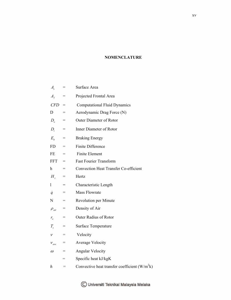
NOMENCLATURE
sA = Surface Area
fA = Projected Frontal Area
CFD = Computational Fluid Dynamics
D = Aerodynamic Drag Force (N)
oD = Outer Diameter of Rotor
iD = Inner Diameter of Rotor
bE = Braking Energy
FD = Finite Difference
FE = Finite Element
FFT = Fast Fourier Transform
h = Convection Heat Transfer Co-efficient
zH = Hertz
l = Characteristic Length
q = Mass Flowrate
N = Revolution per Minute
air = Density of Air
or = Outer Radius of Rotor
sT = Surface Temperature
= Velocity
ave = Average Velocity
= Angular Velocityܿ = Specific heat kJ/kgK݄ோ = Convective heat transfer coefficient (W/m2k)
xvi
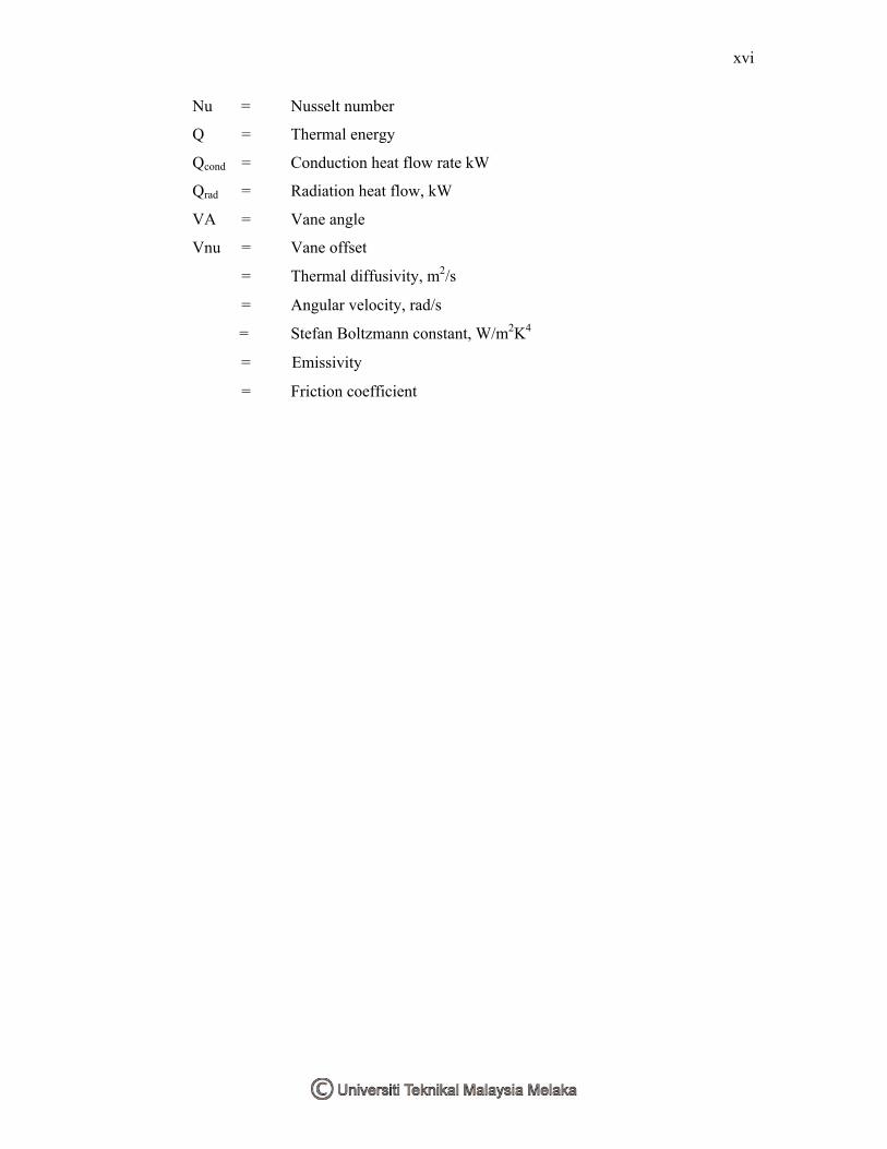
Nu = Nusselt number
Q = Thermal energy
Qcond = Conduction heat flow rate kW
Qrad = Radiation heat flow, kW
VA = Vane angle
Vnu = Vane offset糠 = Thermal diffusivity, m2/s降 = Angular velocity, rad/s購 = Stefan Boltzmann constant, W/m
2K
4綱 = Emissivity航 = Friction coefficient
1
CHAPTER I
INTRODUCTION
1.0 Background of Research
The disc brake is a device for slowing or stopping the rotation of a wheel. The
brake caliper is forced mechanically or pneumatically against both sides of the disc
of the heavy truck to stop the vehicle. The friction between the pads with the disc
rotor of the heavy truck leads to heat flux generation which can be significantly can
decrease the braking performance. The rate of heat generation is due to the kinetic
energy and potential energy were transferred into thermal energy during the braking
process are depends on the vehicles mass, velocity, and rate of deceleration. The
large amount of heat is created and has to be absorbed by brake components in a very
short space of time and the allowable temperatures of the brake and surrounding
components have a limited amount of thermal energy a brake can be stored. The
absorbed heat must be effectively dissipated through the ventilated disc rotor to
achieve satisfactory performance of the braking system. The cooling process of heat
transfer is dissipated through convection, conduction and radiation. The finite
element analysis is used to predict the thermal distribution inside the rotor in steady
state and transient condition.
2
1.2 Objectives of the Study
The research focuses on thermal stress analysis on the solid state condition and
during the transient condition to show the temperature distribution of disc brake of
the heavy truck. The main objectives of this study are:
To understand the working principles, components, standard & theories
through a literature study.
To understand the working principle of FEA software (ABAQUS).
To analyze the thermal distribution on brake disc when the friction
occur at the each cycle of the repeating braking and also the effect of
the thermal distribution.
To clearly justify the result of the thermal stress analysis of the front brake
disc rotor.
1.3 Scope
The scopes of the thermal stress analysis on brake disc rotors are:
Literature review on the working principles, components, standard and
theories.
Construction of 2D & 3D model of disc brake rotor
FE model (Meshing of geometry model)
Finite element analysis on steady state & transient analysis which shows
the temperature distribution of disc brake rotor
Final justification of the thermal stress analysis on the heavy truck
brake disc rotor.
3
1.4 Problems of Statement
The kinetic energy of a vehicle increases with the square of its velocity which
makes it possible to stop a vehicle within a shorter period of time. This leads to very
high power rates transmitted to the rotor disk. The kinetic energy of the heavy truck
is transformed into heat energy which is can’t dissipate fast enough into the air
stream from the brake to the ventilated brake disc rotor.
There are two main problem of brake disc related with thermal such as
excessive heat and severe thermal distortion. For heavy truck its required high power
rates transmitted to brake pad to stop the rotor disc within shorter period of time. The
friction between the brake pad with brake disc rotor produce the non-uniform
excessive heat along the rotor surface due the rotor is rotating. The different
temperatures in shorter period of time create thermal stress which caused by the
changing of disc thickness. The high energy required to be handled by the rotor can
lead to disk surface failure. In particular, it is recognized that repeated severe brake
application under high speed driving may lead to thermal cracking of brake rotors
due to inelastic cyclic strain accumulation .The rate of heat dissipated out from the
rotor is low due to the short braking period as the conduction and convection are not
large enough to take it all away. Thus the surface temperature rises much more
rapidly than the main body of the disk and undergoes higher expansion. If the
temperature gradient is steep enough, compressive plastic strain are generated at the
surface and while cooling afterwards tensile residual stresses are induced which may
be great enough to cause surface failure in one cycle . Thermal judder occurs as a
result of non-uniform contact cycles between the pad and the disk brake rotor, which
is primarily an effect of the localized Thermo-Elastic Instabilities (TEI) at the disk
brake rotor surface. Localized TEI act at the friction ring surface generating
intermittent hot bands around the rubbing path which may in turn leads to the
development of hot spots, (D.Eggleston, 2000)
4
1.5 PSM Structure
The structure of this research is as follows:
Chapters 1 introduce the objective of the research, scope of the work and also include
the problem of statement.
Chapter 2 provides basic information on the selected model heavy truck, the working
component of brake disc, theory of the heat transfer inside the rotor, the information
about the finite element analysis and includes a detailed review of the relevant
background literature.
Chapter 3 describes the heat flux analysis of the heavy truck and also the calculation
of the cooling process at the brake disc surface due to the force convection.
Chapter 4 provides the step used of the finite element modeling by using ABAQUS
software.
Chapter 5 includes the result thermal stress analysis of the both condition at the each
cycle of the repeated braking and followed by the validation of the result by using the
analytical solution method.
Chapter 6 covers the conclusion based on the result of the experiment and the
suggested recommendation of the research in the future.
5
CHAPTER II
LITERATURE REVIEW
2.1 Overview
In this chapter, the working principle of the typical components of commercial
vehicle (heavy truck) brake disc rotor are explained and the heat flux generated due
to the friction are absorbed by the brake disc rotor itself and the heat dissipated
through the atmosphere via convection, conduction and radiation to the nearby
component. The increasing temperature due to frictional heat generation cause axial
and radial deformation of the rotor along with pad expansion. The resulting change
in shape affects the contact between the rotor and pad surface area and thus will
influence the load distribution at the friction interface that can lead to the disc surface
failure. The discussion concepts of the heat transfer are explained including the
boundary condition, thermal transient and also modeling consideration. The finite
element analysis (ABAQUS software) is being used for detailed visualization of
where structures bend or twist and indicates the distribution of stresses inside the
rotor surface. The history of brake disc development and the typical component of air
disc brake will be discussed at the next section.
6
2.2 Introduction of Braking System
The most important system in any commercial vehicle and critical for its safe
operation is a brake system. The brake system are used ensure the safety control of a
vehicle during the braking and enable the vehicle to a smooth stop within the shortest
possible distance under the emergency situations, normal operation and also parking
brakes.
The efficient brake system on any type of vehicle are must be able to provide
the necessary braking torque to the wheel to control the vehicle while dissipate the
heat flux generated due to the friction between the brake pad with the brake disc
rotor. The braking action is usually achieved by mounting the brake on the wheel as
known as the foundation brakes that apply a braking torque directly on the wheel.
The another type of braking actions is by using the brakes on the transmission shaft
of the vehicle that generates higher braking force at the wheel compare to the
foundation brakes but can only provide low braking torque at low vehicle speed,
(T.K. Garrett, 2001).
This research focused on the air brake disc system which widely used in
commercial vehicle such as trucks, tractor-trailer combination and buses. Truck
brakes rely on friction and brake lining material to provide sufficient torque to slow
and stop a vehicle weighing as much as 80,000 pounds within a reasonable distance.
Repeated or continuous brake use (such as on long or steep hills) generates high
temperatures that cause the brake linings to lose effectiveness either from fading or
disintegration. Thus, on a 60 percent grade, an 80,000-pound tractor-trailer requires
167 times more braking power than a 3,000-pound passenger car, even though the
tractor-trailer weighs only 27 times more sources from National Highway Traffic
Safety Administration of USA.
7
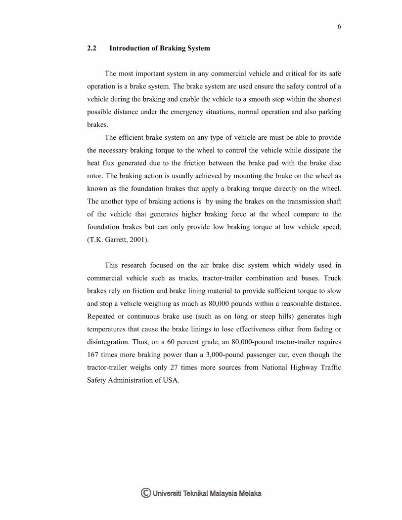
Figure 2.1 Stopping distances of heavy air braked vehicles from 60 mph on dry road
(Source: NHTSA, 1988)
The commercial vehicle brakes are designed and balanced for fully loaded
condition and this result excessive heat generated. The braking performance of
commercial vehicle is governed by the Federal Motor Carrier Safety Regulation
(FMCSR) Part 393. These regulations specify the stopping distance, deceleration and
brake force that should be achieved during stopping.
8
2.3 History
The early years of automotive development were an interesting time for the
designing engineers where the period of innovation without established practice and
virtually all ideas were new ones and worth trying. The development of the braking
system is quite rapidly, however the design of many components stabilized in
concept and so it was with brakes; the majority of vehicles soon adopted drum. The
need for an efficient braking system became more relevant as the speed of the cars
increased especially for emergency stop purpose.
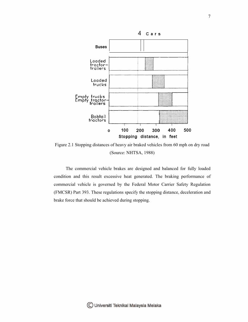
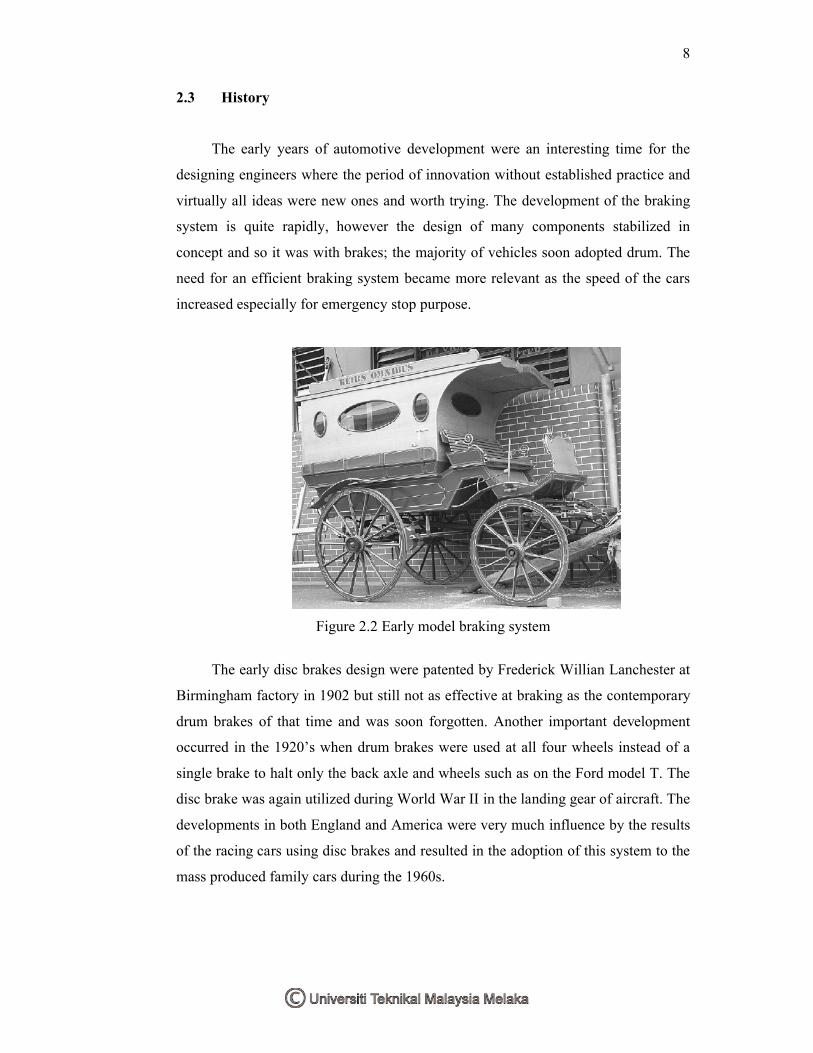
Figure 2.2 Early model braking system
The early disc brakes design were patented by Frederick Willian Lanchester at
Birmingham factory in 1902 but still not as effective at braking as the contemporary
drum brakes of that time and was soon forgotten. Another important development
occurred in the 1920’s when drum brakes were used at all four wheels instead of a
single brake to halt only the back axle and wheels such as on the Ford model T. The
disc brake was again utilized during World War II in the landing gear of aircraft. The
developments in both England and America were very much influence by the results
of the racing cars using disc brakes and resulted in the adoption of this system to the
mass produced family cars during the 1960s.