Embed Size (px)
Citation preview
Thermal SystemsH-Ranges
be different. make a difference.
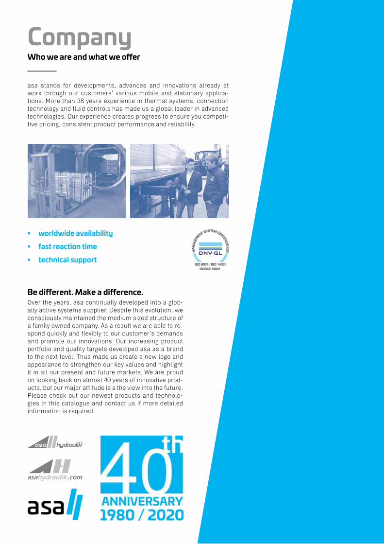
CompanyWho we are and what we offer
asa stands for developments, advances and innovations already at work through our customers’ various mobile and stationary applica-tions. More than 38 years experience in thermal systems, connection technology and fluid controls has made us a global leader in advanced technologies. Our experience creates progress to ensure you competi-tive pricing, consistent product performance and reliability.
worldwide availability
fast reaction time
technical support
Be different. Make a difference.Over the years, asa continually developed into a glob-ally active systems supplier. Despite this evolution, we consciously maintained the medium sized structure of a family owned company. As a result we are able to re-spond quickly and flexibly to our customer’s demands and promote our innovations. Our increasing product portfolio and quality targets developed asa as a brand to the next level. Thus made us create a new logo and appearance to strengthen our key values and highlight it in all our present and future markets. We are proud on looking back on almost 40 years of innovative prod-ucts, but our major attitude is a the view into the future. Please check out our newest products and technolo-gies in this catalogue and contact us if more detailed information is required.
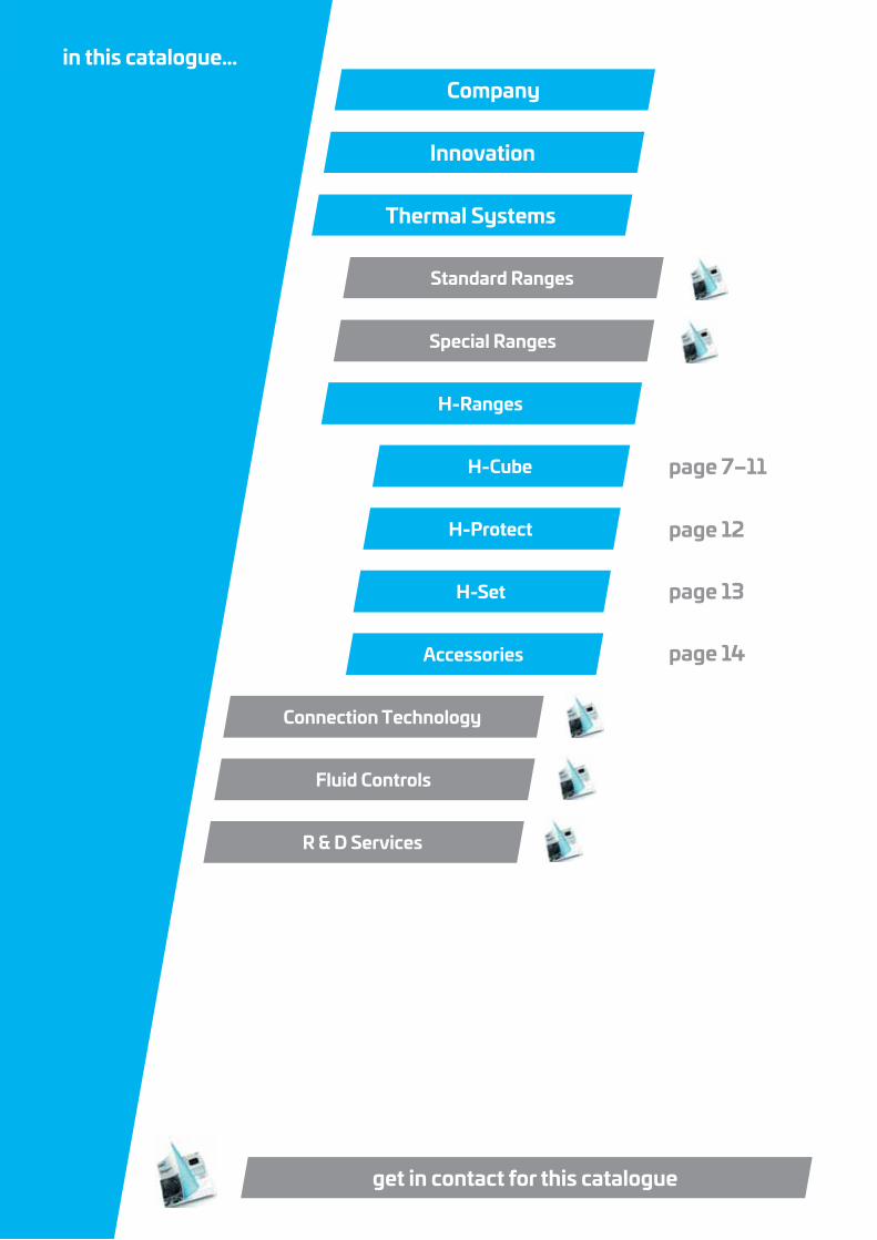
Vibration AbsorberMDGQ Absorberin this catalogue…
Company
Innovation
Thermal Systems
Standard Ranges
Special Ranges
page 7–11
page 12
page 13
page 14
H-Ranges
H-Cube
H-Protect
H-Set
Accessories
Connection Technology
Fluid Controls
R & D Services
get in contact for this catalogue
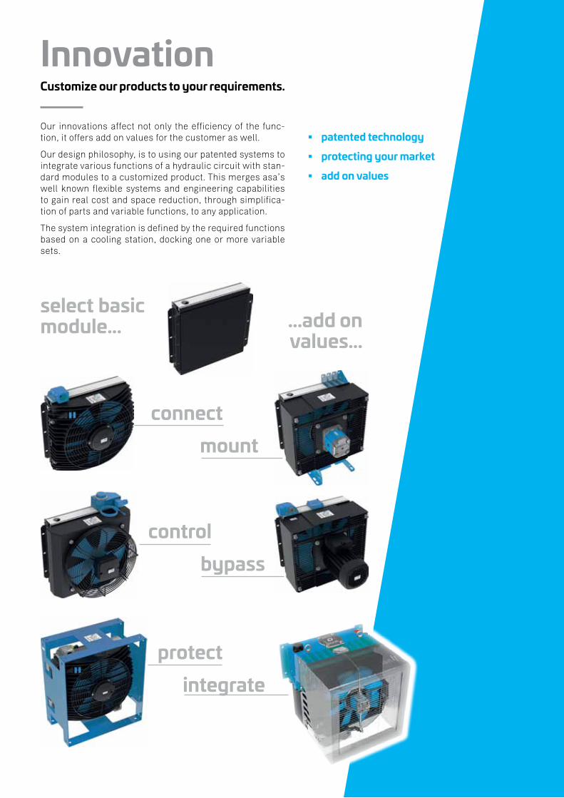
InnovationCustomize our products to your requirements.
Our innovations affect not only the efficiency of the func-tion, it offers add on values for the customer as well.
Our design philosophy, is to using our patented systems to integrate various functions of a hydraulic circuit with stan-dard modules to a customized product. This merges asa’s well known flexible systems and engineering capabilities to gain real cost and space reduction, through simplifica-tion of parts and variable functions, to any application.
The system integration is defined by the required functions based on a cooling station, docking one or more variable sets.
patented technology
protecting your market
add on values
select basic module… …add on
values…
connectmount
controlbypass
protectintegrate
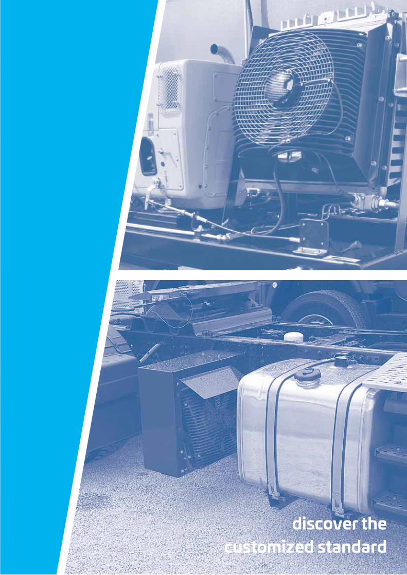
discover the customized standard
real compact design
cost saving
one system
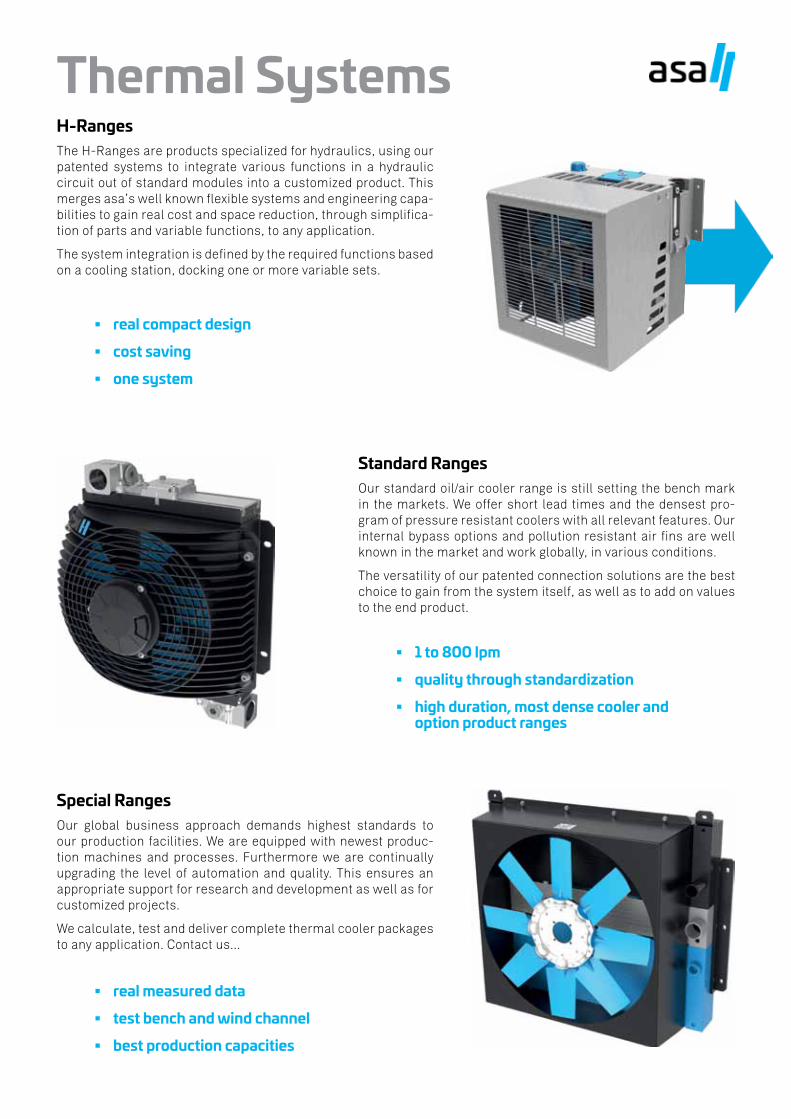
Thermal SystemsH-RangesThe H-Ranges are products specialized for hydraulics, using our patented systems to integrate various functions in a hydraulic circuit out of standard modules into a customized product. This merges asa’s well known flexible systems and engineering capa-bilities to gain real cost and space reduction, through simplifica-tion of parts and variable functions, to any application.
The system integration is defined by the required functions based on a cooling station, docking one or more variable sets.
Standard RangesOur standard oil/air cooler range is still setting the bench mark in the markets. We offer short lead times and the densest pro-gram of pressure resistant coolers with all relevant features. Our internal bypass options and pollution resistant air fins are well known in the market and work globally, in various conditions.
The versatility of our patented connection solutions are the best choice to gain from the system itself, as well as to add on values to the end product.
1 to 800 lpm
quality through standardization
high duration, most dense cooler and option product ranges
Special RangesOur global business approach demands highest standards to our production facilities. We are equipped with newest produc-tion machines and processes. Furthermore we are continually upgrading the level of automation and quality. This ensures an appropriate support for research and development as well as for customized projects.
We calculate, test and deliver complete thermal cooler packages to any application. Contact us...
real measured data
test bench and wind channel
best production capacities
This data sheet and the corresponding scale drawings are to be used as a general guideline and technical overview of our products. Please contact us if more exact information is needed. As we are constantly improving our products, their characteristics, dimensions and weights may also change, although we do our best to incorporate these changes continually. asa assumes no liability for any information therein, any errors, omissions, misprints, nor any direct or indirect damages, losses or costs resulting therefrom. Any cooling performances and general technical values indicated in this catalogue are measured at a test bench according to asa testing procedures or calculated, based on such tests. Due to different conditions in testing and application environments the performance may also vary by +/- 15%. Because there is no standardized testing procedure, tests used by other manufacturers could have different results. Therefore we recommend all products to be checked under the system operating conditions. This is also true for vibrations and mechanical stress as well as for pressure peaks and thermal stress and any other relevant factors. General tolerances according to DIN ISO 2768-v, General tolerances for casted parts according EN ISO 8062-3 (DCTG 10). Tolerances for rubber parts are according to ISO 3302-1 (class M4-F+C).. The tolerances of welding seams are defined by quality group D according to EN ISO 10042, if it is not specified on the actual scale drawing or data sheet. In addition to that we point out that any data sheet and corresponding scale drawing is no substitution for the manual.
© asa hydraulik, December 2018 7
H-CubeModular cooler, filter, tank and control link
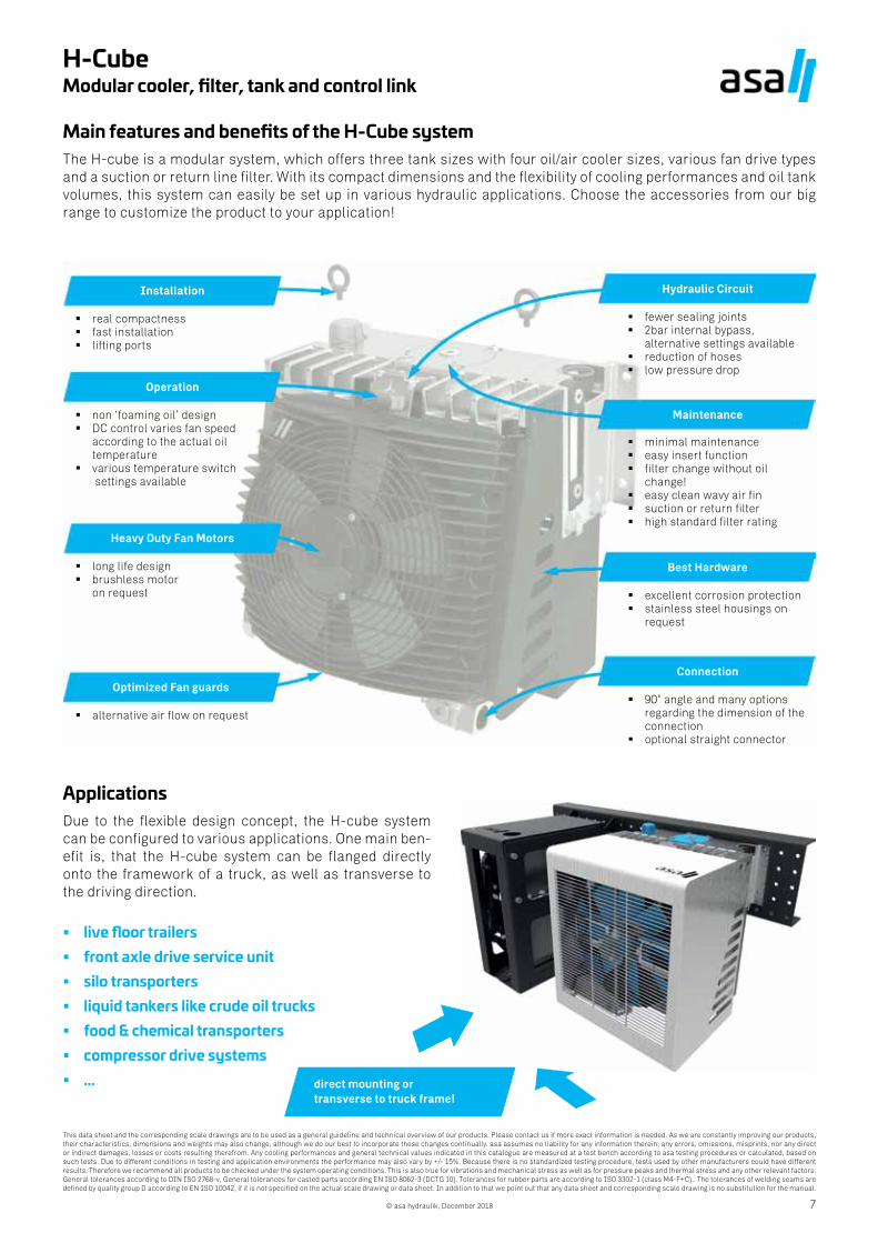
Main features and benefits of the H-Cube systemThe H-cube is a modular system, which offers three tank sizes with four oil/air cooler sizes, various fan drive types and a suction or return line filter. With its compact dimensions and the flexibility of cooling performances and oil tank volumes, this system can easily be set up in various hydraulic applications. Choose the accessories from our big range to customize the product to your application!
real compactness fast installation lifting ports
Installation
Operation
non ‘foaming oil’ design DC control varies fan speed
according to the actual oil temperature
various temperature switch settings available
Heavy Duty Fan Motors
long life design brushless motor
on request
Optimized Fan guards
alternative air flow on request
Hydraulic Circuit
Maintenance
Best Hardware
Connection
fewer sealing joints 2bar internal bypass,
alternative settings available reduction of hoses low pressure drop
minimal maintenance easy insert function filter change without oil
change! easy clean wavy air fin suction or return filter high standard filter rating
excellent corrosion protection stainless steel housings on
request
90° angle and many options regarding the dimension of the connection
optional straight connector
ApplicationsDue to the flexible design concept, the H-cube system can be configured to various applications. One main ben-efit is, that the H-cube system can be flanged directly onto the framework of a truck, as well as transverse to the driving direction.
live floor trailers front axle drive service unit silo transporters liquid tankers like crude oil trucks food & chemical transporters compressor drive systems … direct mounting or
transverse to truck frame!
This data sheet and the corresponding scale drawings are to be used as a general guideline and technical overview of our products. Please contact us if more exact information is needed. As we are constantly improving our products, their characteristics, dimensions and weights may also change, although we do our best to incorporate these changes continually. asa assumes no liability for any information therein, any errors, omissions, misprints, nor any direct or indirect damages, losses or costs resulting therefrom. Any cooling performances and general technical values indicated in this catalogue are measured at a test bench according to asa testing procedures or calculated, based on such tests. Due to different conditions in testing and application environments the performance may also vary by +/- 15%. Because there is no standardized testing procedure, tests used by other manufacturers could have different results. Therefore we recommend all products to be checked under the system operating conditions. This is also true for vibrations and mechanical stress as well as for pressure peaks and thermal stress and any other relevant factors. General tolerances according to DIN ISO 2768-v, General tolerances for casted parts according EN ISO 8062-3 (DCTG 10). Tolerances for rubber parts are according to ISO 3302-1 (class M4-F+C).. The tolerances of welding seams are defined by quality group D according to EN ISO 10042, if it is not specified on the actual scale drawing or data sheet. In addition to that we point out that any data sheet and corresponding scale drawing is no substitution for the manual.
© asa hydraulik, December 20188
H-CubeModular cooler, filter, tank and control link
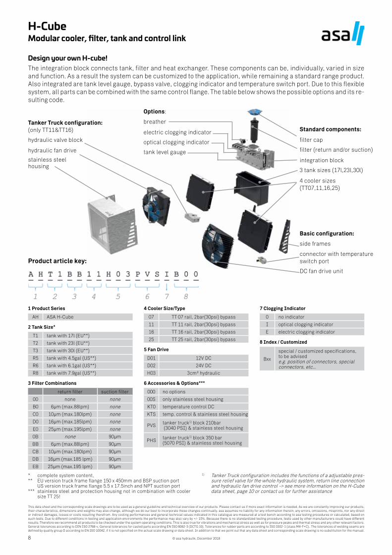
Design your own H-cube!The integration block connects tank, filter and heat exchanger. These components can be, individually, varied in size and function. As a result the system can be customized to the application, while remaining a standard range product. Also integrated are tank level gauge, bypass valve, clogging indicator and temperature switch port. Due to this flexible system, all parts can be combined with the same control flange. The table below shows the possible options and its re-sulting code.
Tanker Truck configuration:(only TT11&TT16)
hydraulic valve block
hydraulic fan drive
stainless steel housing
Options:
breather
electric clogging indicator
optical clogging indicator
tank level gauge
Standard components:
filter cap
filter (return and/or suction)
integration block
3 tank sizes (17l,23l,30l)
4 cooler sizes(TT07,11,16,25)
Basic configuration:
side frames
connector with temperatureswitch port
DC fan drive unit
Product article key:
1 Product Series
AH ASA H-Cube
2 Tank Size*
T1 tank with 17l (EU**)
T2 tank with 23l (EU**)
T3 tank with 30l (EU**)
R5 tank with 4.5gal (US**)
R6 tank with 6.1gal (US**)
R8 tank with 7.9gal (US**)
3 Filter Combinations
return filter suction filter
00 none none
B0 6µm (max.88lpm) none
C0 10µm (max.180lpm) none
D0 16µm (max.185lpm) none
E0 25µm (max.195lpm) none
0B none 90µm
BB 6µm (max.88lpm) 90µm
CB 10µm (max.180lpm) 90µm
DB 16µm (max.185 lpm) 90µm
EB 25µm (max.195 lpm) 90µm
4 Cooler Size/Type
07 TT 07 rail, 2bar(30psi) bypass
11 TT 11 rail, 2bar(30psi) bypass
16 TT 16 rail, 2bar(30psi) bypass
25 TT 25 rail, 2bar(30psi) bypass
5 Fan Drive
D01 12V DC
D02 24V DC
H03 3cm³ hydraulic
6 Accessories & Options***
000 no options
00S only stainless steel housing
KT0 temperature control DC
KTS temp. control & stainless steel housing
PVS tanker truck1) block 210bar (3040 PSI) & stainless steel housing
PHS tanker truck1) block 350 bar (5070 PSI) & stainless steel housing
7 Clogging Indicator
0 no indicator
I optical clogging indicator
E electric clogging indicator
8 Index / Customized
Bxx
special / customized specifications, to be advisede.g. position of connectors, special connectors, etc…
* complete system content, ** EU version truck frame flange 150 x 450mm and BSP suction port US version truck frame flange 5.5 x 17.5inch and NPT suction port*** stainless steel and protection housing not in combination with cooler
size TT 25!
1) Tanker Truck configuration includes the functions of a adjustable pres-sure relief valve for the whole hydraulic system, return line connection and hydraulic fan drive control -> see more information on the H-Cube data sheet, page 10 or contact us for further assistance
This data sheet and the corresponding scale drawings are to be used as a general guideline and technical overview of our products. Please contact us if more exact information is needed. As we are constantly improving our products, their characteristics, dimensions and weights may also change, although we do our best to incorporate these changes continually. asa assumes no liability for any information therein, any errors, omissions, misprints, nor any direct or indirect damages, losses or costs resulting therefrom. Any cooling performances and general technical values indicated in this catalogue are measured at a test bench according to asa testing procedures or calculated, based on such tests. Due to different conditions in testing and application environments the performance may also vary by +/- 15%. Because there is no standardized testing procedure, tests used by other manufacturers could have different results. Therefore we recommend all products to be checked under the system operating conditions. This is also true for vibrations and mechanical stress as well as for pressure peaks and thermal stress and any other relevant factors. General tolerances according to DIN ISO 2768-v, General tolerances for casted parts according EN ISO 8062-3 (DCTG 10). Tolerances for rubber parts are according to ISO 3302-1 (class M4-F+C).. The tolerances of welding seams are defined by quality group D according to EN ISO 10042, if it is not specified on the actual scale drawing or data sheet. In addition to that we point out that any data sheet and corresponding scale drawing is no substitution for the manual.
© asa hydraulik, December 2018 9
H-CubeModular cooler, filter, tank and control link
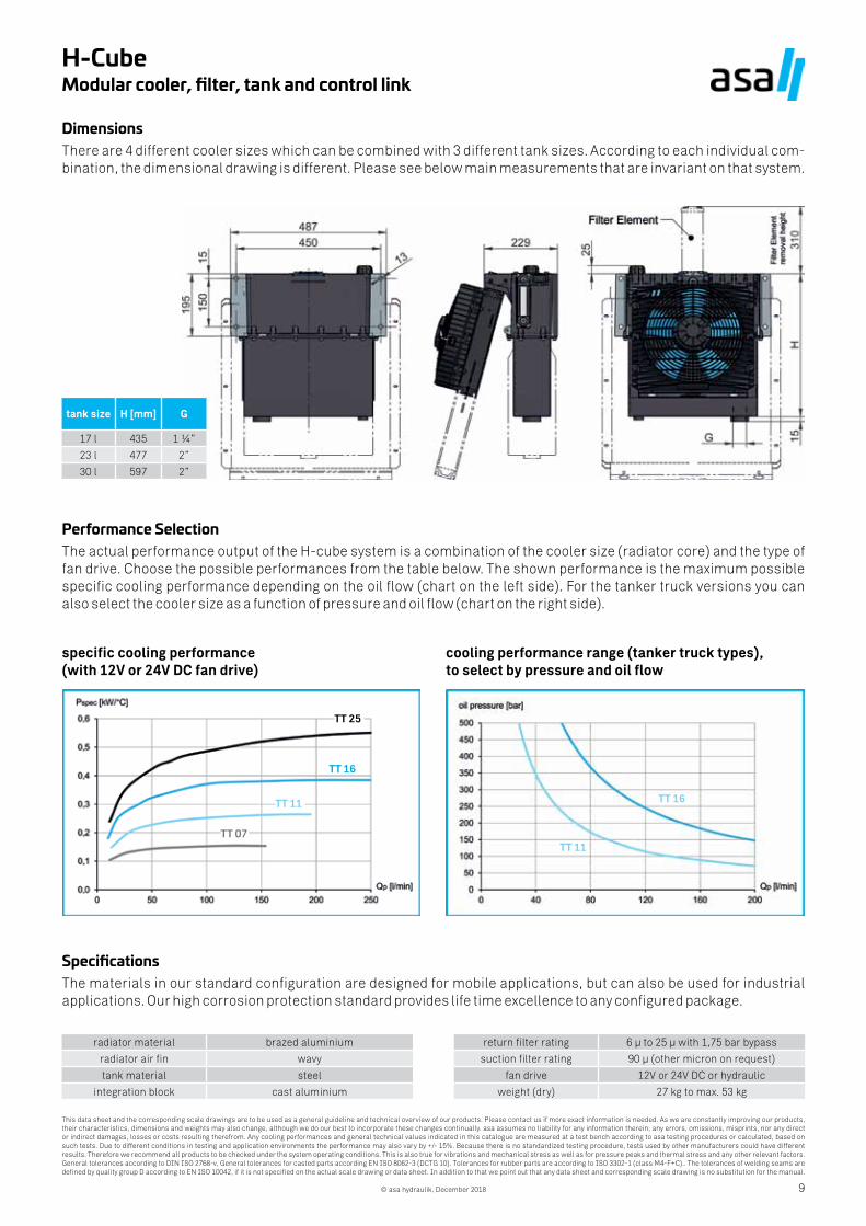
DimensionsThere are 4 different cooler sizes which can be combined with 3 different tank sizes. According to each individual com-bination, the dimensional drawing is different. Please see below main measurements that are invariant on that system.
Performance SelectionThe actual performance output of the H-cube system is a combination of the cooler size (radiator core) and the type of fan drive. Choose the possible performances from the table below. The shown performance is the maximum possible specific cooling performance depending on the oil flow (chart on the left side). For the tanker truck versions you can also select the cooler size as a function of pressure and oil flow (chart on the right side).
specific cooling performance (with 12V or 24V DC fan drive)
cooling performance range (tanker truck types), to select by pressure and oil flow
tank size H [mm] G
17 l 435 1 ¼”
23 l 477 2”
30 l 597 2”
SpecificationsThe materials in our standard configuration are designed for mobile applications, but can also be used for industrial applications. Our high corrosion protection standard provides life time excellence to any configured package.
radiator material brazed aluminium
radiator air fin wavy
tank material steel
integration block cast aluminium
return filter rating 6 µ to 25 µ with 1,75 bar bypass
suction filter rating 90 µ (other micron on request)
fan drive 12V or 24V DC or hydraulic
weight (dry) 27 kg to max. 53 kg
TT 16
TT 11
TT 07
TT 16
TT 11
TT 25
This data sheet and the corresponding scale drawings are to be used as a general guideline and technical overview of our products. Please contact us if more exact information is needed. As we are constantly improving our products, their characteristics, dimensions and weights may also change, although we do our best to incorporate these changes continually. asa assumes no liability for any information therein, any errors, omissions, misprints, nor any direct or indirect damages, losses or costs resulting therefrom. Any cooling performances and general technical values indicated in this catalogue are measured at a test bench according to asa testing procedures or calculated, based on such tests. Due to different conditions in testing and application environments the performance may also vary by +/- 15%. Because there is no standardized testing procedure, tests used by other manufacturers could have different results. Therefore we recommend all products to be checked under the system operating conditions. This is also true for vibrations and mechanical stress as well as for pressure peaks and thermal stress and any other relevant factors. General tolerances according to DIN ISO 2768-v, General tolerances for casted parts according EN ISO 8062-3 (DCTG 10). Tolerances for rubber parts are according to ISO 3302-1 (class M4-F+C).. The tolerances of welding seams are defined by quality group D according to EN ISO 10042, if it is not specified on the actual scale drawing or data sheet. In addition to that we point out that any data sheet and corresponding scale drawing is no substitution for the manual.
© asa hydraulik, December 201810
H-CubeModular cooler, filter, tank and control link
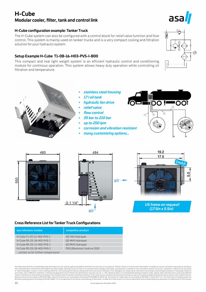
H-Cube configuration example: Tanker TruckThe H-Cube system can also be configured with a control block for relief valve function and flow control. This system is mainly used on tanker trucks and is a very compact cooling and filtration solution for your hydraulic system.
Setup Example H-Cube T1-0B-16-H03-PVS-I-B00This compact and real light weight system is an efficient hydraulic control and conditioning module for continous operation. This system allows heavy duty operation while controlling oil filtration and temperature.
stainless steel housing 17 l oil tank hydraulic fan drive relief valve flow control 35 bar to 210 bar up to 250 lpm corrosion and vibration resistant many customizing options…
US frame on request! (17.5in x 5.5in)
[inch]!
Cross Reference List for Tanker Truck Configurations
asa reference number competitor product
H-Cube T1-C0-11-H03-PVS-I GD HK3 Hydrapak
H-Cube R5-C0-16-H03-PVS-I GD MH5 Hydrapak
H-Cube R5-C0-11-H03-PVS-I GD MH3 Hydrapak
H-Cube R5-C0-16-H03-PHS-I PSG (Blackmer) Hydrive 2020
...contact us for further comparisons!
This data sheet and the corresponding scale drawings are to be used as a general guideline and technical overview of our products. Please contact us if more exact information is needed. As we are constantly improving our products, their characteristics, dimensions and weights may also change, although we do our best to incorporate these changes continually. asa assumes no liability for any information therein, any errors, omissions, misprints, nor any direct or indirect damages, losses or costs resulting therefrom. Any cooling performances and general technical values indicated in this catalogue are measured at a test bench according to asa testing procedures or calculated, based on such tests. Due to different conditions in testing and application environments the performance may also vary by +/- 15%. Because there is no standardized testing procedure, tests used by other manufacturers could have different results. Therefore we recommend all products to be checked under the system operating conditions. This is also true for vibrations and mechanical stress as well as for pressure peaks and thermal stress and any other relevant factors. General tolerances according to DIN ISO 2768-v, General tolerances for casted parts according EN ISO 8062-3 (DCTG 10). Tolerances for rubber parts are according to ISO 3302-1 (class M4-F+C).. The tolerances of welding seams are defined by quality group D according to EN ISO 10042, if it is not specified on the actual scale drawing or data sheet. In addition to that we point out that any data sheet and corresponding scale drawing is no substitution for the manual.
© asa hydraulik, December 2018 11
H-CubeModular cooler, filter, tank and control link
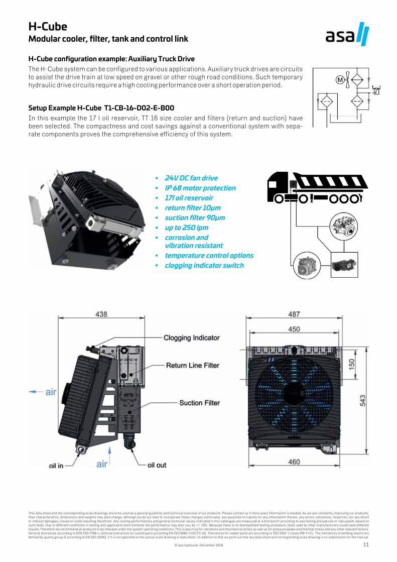
H-Cube configuration example: Auxiliary Truck DriveThe H-Cube system can be configured to various applications. Auxiliary truck drives are circuits to assist the drive train at low speed on gravel or other rough road conditions. Such temporary hydraulic drive circuits require a high cooling performance over a short operation period.
Setup Example H-Cube T1-CB-16-D02-E-B00In this example the 17 l oil reservoir, TT 16 size cooler and filters (return and suction) have been selected. The compactness and cost savings against a conventional system with sepa-rate components proves the comprehensive efficiency of this system.
24V DC fan drive IP 68 motor protection 17l oil reservoir return filter 10µm suction filter 90µm up to 250 lpm corrosion and
vibration resistant temperature control options clogging indicator switch
This data sheet and the corresponding scale drawings are to be used as a general guideline and technical overview of our products. Please contact us if more exact information is needed. As we are constantly improving our products, their characteristics, dimensions and weights may also change, although we do our best to incorporate these changes continually. asa assumes no liability for any information therein, any errors, omissions, misprints, nor any direct or indirect damages, losses or costs resulting therefrom. Any cooling performances and general technical values indicated in this catalogue are measured at a test bench according to asa testing procedures or calculated, based on such tests. Due to different conditions in testing and application environments the performance may also vary by +/- 15%. Because there is no standardized testing procedure, tests used by other manufacturers could have different results. Therefore we recommend all products to be checked under the system operating conditions. This is also true for vibrations and mechanical stress as well as for pressure peaks and thermal stress and any other relevant factors. General tolerances according to DIN ISO 2768-v, General tolerances for casted parts according EN ISO 8062-3 (DCTG 10). Tolerances for rubber parts are according to ISO 3302-1 (class M4-F+C).. The tolerances of welding seams are defined by quality group D according to EN ISO 10042, if it is not specified on the actual scale drawing or data sheet. In addition to that we point out that any data sheet and corresponding scale drawing is no substitution for the manual.
© asa hydraulik, December 201812
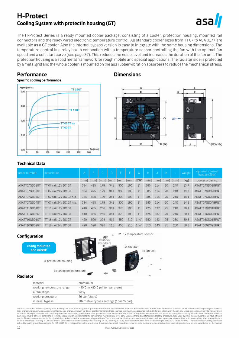
H-ProtectCooling System with protectin housing (GT)
The H-Protect Series is a ready mounted cooler package, consisting of a cooler, protection housing, mounted rail connectors and the ready wired electronic temperature control. All standard cooler sizes from TT 07 to ASA 0177 are available as a GT cooler. Also the internal bypass version is easy to integrate with the same housing dimensions. The temperature control is a relay box in connection with a temperature sensor controlling the fan with the optimal fan speed and a soft start curve (see page 37). This reduces the noise level and increases the duration of the fan unit. The protection housing is a solid metal framework for rough mobile and special applications. The radiator side is protected by a metal grid and the whole cooler is mounted on the asa rubber vibration absorbers to reduce the mechanical stress.
PerformanceSpecific cooling performance
Dimensions
Technical Data
order number description A B C D E F G H J K L weight optional internalbypass (2bar)
[mm] [mm] [mm] [mm] [mm] [mm] BSP [mm] [mm] [mm] [mm] [kg] cooler order no.
ASATT07GD01GT TT 07 rail 12V DC GT 334 425 179 341 300 190 1” 385 114 20 240 13,7 ASATT07GD01BPGT
ASATT07GD02GT TT 07 rail 24V DC GT 334 425 179 341 300 190 1” 385 114 20 240 13,7 ASATT07GD02BPGT
ASATT07GD03GT TT 07 rail 12V DC GT h.p. 334 425 179 341 300 190 1” 385 114 20 240 14,1 ASATT07GD03BPGT
ASATT07GD04GT TT 07 rail 24V DC GT h.p. 334 425 179 341 300 190 1” 385 114 20 240 14,1 ASATT07GD04BPGT
ASATT11GD01GT TT 11 rail 12V DC GT 410 465 256 381 370 190 1” 425 137 25 240 20,1 ASATT11GD01BPGT
ASATT11GD02GT TT 11 rail 24V DC GT 410 465 256 381 370 190 1” 425 137 25 240 20,1 ASATT11GD02BPGT
ASATT16GD01GT TT 16 rail 12V DC GT 490 590 328 515 450 210 1 ¼” 550 143 25 260 30,3 ASATT16GD01BPGT
ASATT16GD02GT TT 16 rail 24V DC GT 490 590 328 515 450 210 1 ¼” 550 143 25 260 30,3 ASATT16GD02BPGT
Configuration
ready mounted and wired!
Radiatormaterial aluminium
working temperature range: –20°C to +80°C (oil temperature)
air fin shape: wavy
working pressure: 26 bar (static)
internal bypass alternative bypass settings (1bar / 5 bar)
1x protection housing
1x fan speed control unit
4x shock absorbers
1x temperature sensor
1x radiator1x fan unit
TT 16GT
TT 11GT
TT 07GT ha
TT 07GT
This data sheet and the corresponding scale drawings are to be used as a general guideline and technical overview of our products. Please contact us if more exact information is needed. As we are constantly improving our products, their characteristics, dimensions and weights may also change, although we do our best to incorporate these changes continually. asa assumes no liability for any information therein, any errors, omissions, misprints, nor any direct or indirect damages, losses or costs resulting therefrom. Any cooling performances and general technical values indicated in this catalogue are measured at a test bench according to asa testing procedures or calculated, based on such tests. Due to different conditions in testing and application environments the performance may also vary by +/- 15%. Because there is no standardized testing procedure, tests used by other manufacturers could have different results. Therefore we recommend all products to be checked under the system operating conditions. This is also true for vibrations and mechanical stress as well as for pressure peaks and thermal stress and any other relevant factors. General tolerances according to DIN ISO 2768-v, General tolerances for casted parts according EN ISO 8062-3 (DCTG 10). Tolerances for rubber parts are according to ISO 3302-1 (class M4-F+C).. The tolerances of welding seams are defined by quality group D according to EN ISO 10042, if it is not specified on the actual scale drawing or data sheet. In addition to that we point out that any data sheet and corresponding scale drawing is no substitution for the manual.
© asa hydraulik, December 2018 13
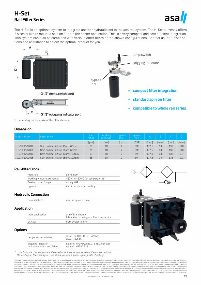
H-SetRail Filter Series
The H-Set is an optional system to integrate another hydraulic set to the asa rail system. The H-Set currently offers 2 sizes of kits to mount a spin on filter to the cooler application. This is a very compact and cost efficient integration. This system can also be combined with various other filters or the shown configurations. Contact us for further op-tions and assistance to select the optimal product for you.
bypassincl.
temp.switch
colgging indicator
Dimension
order number description filter rating
working pressure
bypass incl.
spin on port A B C D
[µm] [bar] [bar] [BSP] [mm] [mm] [mm] [mm]
ILLZRF11G2010 Spin on filter kit rail 10µm, 60lpm 10 10 2 3/4” 177,5 33 135 146
ILLZRF11G2025 Spin on filter kit rail 25µm, 60lpm 25 10 2 3/4” 177,5 33 135 146
ILLZRF12G2010 Spin on filter kit rail 10µm, 100lpm 10 10 2 3/4” 177,5 33 135 191
ILLZRF12G2025 Spin on filter kit rail 25µm, 100lpm 25 10 2 3/4” 177,5 33 135 191
Rail-filter Blockmaterial: aluminium
working temperature range: –20°C to +100°C (oil temperature)*
Sealing to rail flange: o-ring NBR
bypass: incl.2 bar standard setting
Hydraulic Connectioncompatible to any rail system cooler
Applicationmain application are offline circuits,
lubrication, cooling and filration circuits
oil flow from cooler to filter
Options
temperature switches ILLZTH5069K, ILLZTH4765K, ILLZTH6065K
clogging indicator/ indication pressure 1,5 bar
electric: HFZVEG15 N.O. & N.C. contact optical: HFZVOG15
* …the indicated temperature is the maximum inlet temperature for the cooler radiator. Depending on the sealings in use, the application needs appropriate checking.
compact filter integration
standard spin on filter
compatible to whole rail series
*) depending on the make of the filter element
This data sheet and the corresponding scale drawings are to be used as a general guideline and technical overview of our products. Please contact us if more exact information is needed. As we are constantly improving our products, their characteristics, dimensions and weights may also change, although we do our best to incorporate these changes continually. asa assumes no liability for any information therein, any errors, omissions, misprints, nor any direct or indirect damages, losses or costs resulting therefrom. Any cooling performances and general technical values indicated in this catalogue are measured at a test bench according to asa testing procedures or calculated, based on such tests. Due to different conditions in testing and application environments the performance may also vary by +/- 15%. Because there is no standardized testing procedure, tests used by other manufacturers could have different results. Therefore we recommend all products to be checked under the system operating conditions. This is also true for vibrations and mechanical stress as well as for pressure peaks and thermal stress and any other relevant factors. General tolerances according to DIN ISO 2768-v, General tolerances for casted parts according EN ISO 8062-3 (DCTG 10). Tolerances for rubber parts are according to ISO 3302-1 (class M4-F+C).. The tolerances of welding seams are defined by quality group D according to EN ISO 10042, if it is not specified on the actual scale drawing or data sheet. In addition to that we point out that any data sheet and corresponding scale drawing is no substitution for the manual.
© asa hydraulik, December 201814
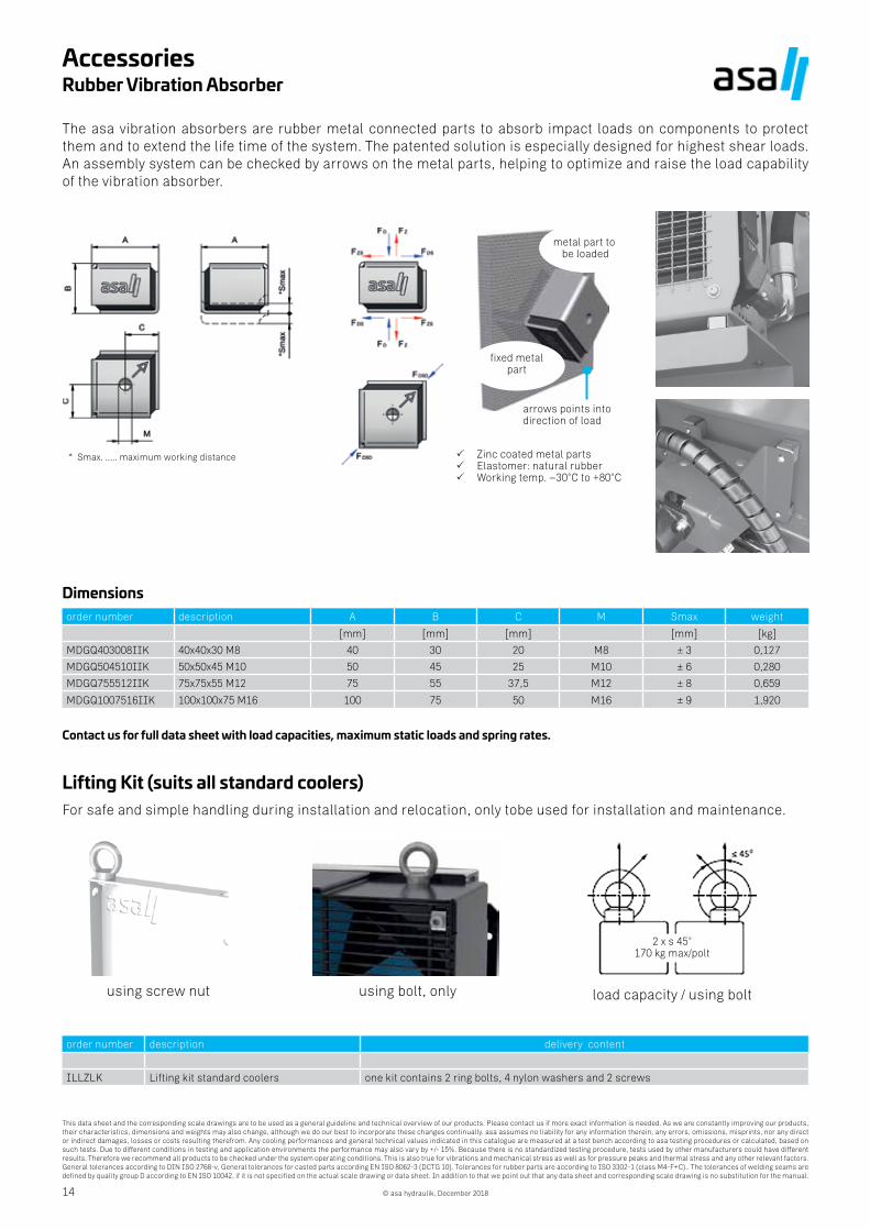
AccessoriesRubber Vibration Absorber
The asa vibration absorbers are rubber metal connected parts to absorb impact loads on components to protect them and to extend the life time of the system. The patented solution is especially designed for highest shear loads. An assembly system can be checked by arrows on the metal parts, helping to optimize and raise the load capability of the vibration absorber.
* Smax. ..... maximum working distance
metal part to be loaded
fixed metalpart
arrows points into direction of load
Zinc coated metal parts Elastomer: natural rubber Working temp. –30°C to +80°C
Dimensionsorder number description A B C M Smax weight
[mm] [mm] [mm] [mm] [kg]
MDGQ403008IIK 40x40x30 M8 40 30 20 M8 ± 3 0,127
MDGQ504510IIK 50x50x45 M10 50 45 25 M10 ± 6 0,280
MDGQ755512IIK 75x75x55 M12 75 55 37,5 M12 ± 8 0,659
MDGQ1007516IIK 100x100x75 M16 100 75 50 M16 ± 9 1,920
Contact us for full data sheet with load capacities, maximum static loads and spring rates.
Lifting Kit (suits all standard coolers)For safe and simple handling during installation and relocation, only tobe used for installation and maintenance.
2 x s 45°170 kg max/polt
using screw nut using bolt, only load capacity / using bolt
order number description delivery content
ILLZLK Lifting kit standard coolers one kit contains 2 ring bolts, 4 nylon washers and 2 screws
15
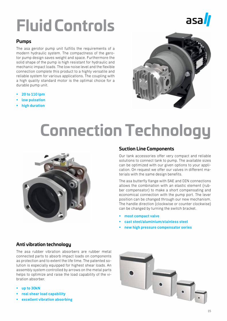
Fluid ControlsPumpsThe asa gerotor pump unit fulfills the requirements of a modern hydraulic system. The compactness of the gero-tor pump design saves weight and space. Furthermore the solid shape of the pump is high resistant for hydraulic and mechanic impact loads. The low noise level and the flexible connection complete this product to a highly versatile and reliable system for various applications. The coupling with a high quality standard motor is the optimal choice for a durable pump unit.
20 to 110 lpm
low pulsation
high duration
Suction Line ComponentsOur tank accessories offer very compact and reliable solutions to connect tank to pump. The available sizes can be optimized with our given options to your appli-cation. On request we offer our valves in different ma-terials with the same design benefits.
The asa butterfly flange with SAE and DIN connections allows the combination with an elastic element (rub-ber compensator) to make a short compensating and economical connection with the pump port. The lever position can be changed through our new mechanism. The handle direction (clockwise or counter clockwise) can be changed by turning the switch bracket.
most compact valve
cast steel/aluminium/stainless steel
new high pressure compensator series
Anti vibration technologyThe asa rubber vibration absorbers are rubber metal connected parts to absorb impact loads on components as protection and to extent the life time. The patented so-lution is especially equipped for highest shear loads. An assembly system controlled by arrows on the metal parts helps to optimize and raise the load capability of the vi-bration absorber.
up to 30kN
real shear load capability
excellent vibration absorbing
Connection Technology
Thermal Systems Connection Technology Fluid Controls
AUSTRIAasa hydraulik GmbHPrager Strasse 280A-1210, ViennaTel.: +43 1 292 40 [email protected]
USAasa hydraulik of America160 Meister Avenue 20 ABranchburg, New Jersey 08876Tel.: +1 800 473 94 00Tel.: +1 908 541 15 [email protected]
CHINA安飒液压科技(苏州)有限公司asa Hydraulik Technology (Suzhou) Co.Ltd江苏省苏州市工业园区方洲路128号6区B幢Area 6, Building B, Fangzhou Road No 128, Suzhou industrial park, Suzhou City, Jiangsu ProvinceTel.: +86 512 [email protected]
AUSTRALIAasa Products Pty LtdBentley Street 4/153016 Williamstown, VictoriaTel.: +61 3 9397 [email protected]
INDIAASAhydraulik India Pvt LtdC1/109/9, GIDC, Palej, Dt.BharuchGujarat – 392220Tel.: +91 22 [email protected]


![Applied Thermal Engineering - DiscreteHeat · 2018. 2. 28. · Applied Thermal Engineering 62 (2014) 382e389. converting from electric to alternative heating systems [3].Asa result](https://img.pdfslide.net/doc/110x75/60bf03726fceba0be61d4dd1/applied-thermal-engineering-discreteheat-2018-2-28-applied-thermal-engineering.jpg)