Embed Size (px)
Citation preview

Znd. Eng. Chem. Res. 1992,31,681-687 681
Burner. Ph.D. Thesis, University of Pennsylvania, Philadelphia, PA, 1987.
Collins, L. R. A Reynolds Stress Model for Low Mach Number Variable-Density Flow. In review, 1991.
Collins, L. R.; Churchill, S. W. Effect of Laminarizing Flow on Poetflame Reactions in a Thermally Stabilized Burner. Znd. Eng. Chem. Res. 1990,29,456-463.
Collins, L. R.; Churchill, S. W. A Numerical Study of the Asymptotic Rate of Decay of Turbulence in Tubes. In review, 1991.
Goepp, J. W.; Tang, H.; Lior, N.; Churchill, S. W. Multiplicity and Pollutant Formation for the Combustion of Hexane in a Refrac- tory Tube. AIChE J. 1980,26,855-858.
Hinze, J. 0. Turbulence, 2nd ed.; McGraw Hill: New York, NY, 1975.
Jones, W. P.; Launder, B. E. Some Properties of Sink-Flow Turbu- lent Boundary Layers. J. Fluid Mech. 1972a, 56, 337-351.
Jones, W. P.; Launder, B. E. The Prediction of Laminarization with a Two-Equation Model of Turbulence. Znt. J. Heat Mass Transfer 1972b, 15, 301.
Jones, W. P.; Launder, B. E. The Calculation of Low-Reynolds- Number Phenomena with a Two-Equation Model of Turbulence. Znt. J. Heat Mass Transfer 1973,16, 1119.
Jones, W. P.; Whitelaw, J. H. Calculation Methods for Reacting Turbulent Flows: A Review. Combust. Flame 1982,48,1.
Launder, B. E.; Jones, W. P. Sink Flow Turbulent Boundary Layers. J. Fluid Mech. 1969,38,817-831.
Libby, P. A.; Bray, K. N. C. Countergradient Diffusion in Premixed Turbulent Flames. AIAA J. 1981,19,205.
McEligot, D. M.; Coon, C. W.; Perkins, H. C. Relaminarization in Tubes. Znt. J. Heat Mass Transfer 1970,13,431.
Narasimha, R.; Sreenivasan, K. R. Relaminarization in Highly Ac- celerated Turbulent Boundary Layers. J. Fluid Mech. 1973,61, 417.
Narasimha, R.; Sreenivasan, K. R. Relaminarization of Fluid Flows. Adv. Appl. Mech. 1979,19, 221-309.
Patel, V. C.; Head, M. R. Reversion of Turbulent to Laminar Flow. J. Fluid Mech. 1968,34, 371.
Pfefferle, L. D.; Churchill, S. W. The Stability of Flames Inside a Refractory Tube. Combust. Flame 1984,56, 165-174.
Schlichting, H. Boundary Layer Theory, 7th ed.; McGraw Hill: New York, NY, 1979.
Smooke, M. D. Solution of Burner-Stabilized Premixed Laminar Flames by Boundary Value Methods. J. Comput. Phys. 1982,48,
Smooke, M. D.; Koszykowski, M. L. Two-Dimensional Fully Adap- tive Solutions of Solid-Solid Alloying Reactions; Sandia Report
Spalart, P. R. NASA Report No. TM-88220, 1986. Tang, S. K.; Churchill, S. W. A Theoretical Model for Combustion
Reactions Inside a Refractory Tube. Chem. Eng. Commun. 1980a, 9, 137-150.
Tang, S. K.; Churchill, S. W. The Prediction of NOx Formation for the Combustion of Nitrogen-Doped Droplets of Hexane Inside a Refractory Tube. Chem. Eng. Commun. 1980b, 9,151-157.
72-105.
NO. SAND83-8909,1964.
Van Driest, E. R. J. Aerosol Sci. 1957,23, 1007. Van Dyke, Perturbation Methods in Fluid Mechanics; The Para-
bolic Press: Stanford, CA, 1975. Wahiduzzaman, S.; Fergwon, C. R. Convective Heat Transfer from
a Decaying Swirling Flow within a Cylinder. Proceedings of the Eighth International Heat Transfer Conference, San Francisco; Hemisphere: Washington, DC, 1986; Vol. 3, pp 987-992.
Received for review April 25, 1991 Revised manuscript received August 7, 1991
Accepted August 22,1991
Thermally Stabilized Combustion as a Means of Studying the Devolatilization of Coal
Christina Chan,? Norio Arai,t Noam Lior,s and Stuart W. Churchill* Department of Chemical Engineering, The University of Pennsylvania, 220 South 33rd Street, Philadelphia, Pennsylvania 19104-6393
Thermally stabilized combustion of premixed ethane and air in a ceramic tube results in a virtual step function in temperature, composition, and velocity at the flame front. If the mixture is fuel-rich, the burned gas consists almost wholly of CO, COz, HzO, and N2. For a tube greater than 30 mm in diameter, the stable range of flow is in the turbulent regime both upstream and downstream from the flame front. An experimental technique exploiting this environment for study of the devola- tilization of coal is described, and illustrative results are presented. As compared with other techniques using heated grids or entrainment, the conditions outside a particle are more uniform and the rate of heating is greater, but the velocity and temperature of the particle must be determined from momentum and energy balances rather than by direct measurement.
Introduction When coal is heated in a vacuum or an inert atmosphere
as much as 75 wt% , depending primarily on ita rank, can be decomposed and volatilized. Hence, devolatilization is an important facet of the processing of coal by com- bustion, gasification, hydropyrolysis, and coking. The rate and extant of devolatilization depend on the rate of heating, the ultimate temperature, and the pressure and
*To whom correspondence should be addressed. 'Current address: E. 1. du Pont Marshall Laboratory, 3500
* Current address: Department of Chemical Engineering,
Department of Mechanical Engineering and Applied Me-
Grays Ferry Road, Philadelphia, PA 19146.
Nagoya University, Nagoya 464, Japan.
chanics, The University of Pennsylvania.
composition of the gaseous environment, as well as on the type of coal and ita granulation. Because of ita importance, the devolatilization of coal has been the subject of many investigations, both experimental and theoretical. How- ever, because of the variety of coals, the number of vari- ables, and the complexity of the process itself, this behavior is not yet completely understood or effectively generalized [see, for example, Solomon and Hamblen (1986) and Niksa (1988)l. A major diffiiulty arises in designing experiments from which the rate of devolatilization can be determined accurately, and for which the environmental conditions are not only defined unambiguously but also represent prac- tical applications. A new experimental technique for this purpose is proposed herein and compared with existing methods. Attention is focused on the principles involved in the new methodology, but representative facilities and
0888-588519212631-0681$03.00/0 0 1992 American Chemical Society
682 Ind. Eng. Chem. Res., Vol. 31, No. 3, 1992
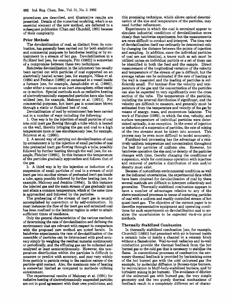
procedures are described, and illustrative results are presented. Details of the numerical modeling, which is an essential element of the new method, are deferred to a subsequent publication (Chan and Churchill, 1991) because of their complexity.
Prior Methods The devolatilization of coal, as distinct from its com-
bustion, has generally been carried out for both analytical and commercial purposes by batchwise heating or by en- trainment in a stream of hot gas. Devolatilization in a flurdized bed [see, for example, Pitt (196211 is somewhat of a compromise between these two techniques.
Batchwise devolatilization in the laboratory has usually been carried out with particles of coal supported on an electrically heated screen [see, for example, Niksa et al. (1984) and Freihaut (1989)] or contained in a vessel inside a furnace [see, for example, Jamaluddin et al. (198611, under either a vacuum or an inert atmosphere, either static or in motion. Special methods such as radiative heating of electrodynamically suspended particles have also been utilized [see, for example, Maloney et al. (1991)l. For commercial purposes, hot inert gas is sometimes blown through a static or fluidized bed of coal.
Devolatilization of coal by entrainment has been carried out in a number of ways including the following:
1. One way is by the injection of small particles of coal into cold inert gas flowing through a tube which is heated on the wall, thereby bringing the gas and coal to a high temperature more or less simultaneously [see, for example, Solomon et al. (1986)l. 2. A second way of carrying out devolatilization of coal
by entrainment is by the injection of small particles of coal into preheated inert gas flowing through a tube, possibly followed by further heating through the wall [see, for ex- ample, Fletcher (1989)J. In this instance the temperature of the particles gradually approaches and follows that of the gas.
3. A third way is by the injection or induction of a suspension of small particles of coal in a stream of cold inert gas into another stream of preheated inert gas inside a tube, again possibly followed by further heating [see, for example, Maloney and Jenkins (1984)l. In this instance the injected gas and the main stream of gas gradually mix and attain a common temperature, which at the same time is approached and followed by the particles.
The preheating of the stream of inert gas is usually accomplished by convection or by self-combustion. In most instances the flow of the inert gas and entrained coal has been confined to the laminar regime in order to attain sufficient times of residence.
Only the general characteristics of the various methods of determining the rate of devolatilization and d e f i g the environment that are relevant with respect to comparison with the proposed new method are noted herein. In batchwise experiments the rate of devolatilization of the ensemble of particles can be determined with good accu- racy simply by weighing the residual material continuously or periodically, and the effluxing gas can be collected and analyzed at least semicontinuously. However, the tem- perature distribution within the particles is difficult to measure or predict with accuracy, and may vary widely from particle to particle owing to the random nature of the particle-grid contact. Also, the maximum rate of heating is somewhat limited as compared to methods utilizing entrainment.
The experimental results of Maloney et al. (1991) for radiative heating of electrodynamically suspended particles are not in good agreement with their own predictions, and
this promising technique, which allows optical determi- nation of the size and temperature of the particles, may need further refinement.
Experiments in which the coal is entrained appear to simulate industrial conditions of devolatilization more closely than batchwise experiments, but the measurements are more difficult to conduct and interpret. The time rate of devolatilization itself can ordinarily be determined only by changing the distance between the points of injection and sampling. In addition, since the individual particles of coal are not identical, a tracer such as ash must be utilized unless an individual particle or a set of them can be identified in both the feed and the sample. Direct measurement of the longitudinal variation of the velocity and temperature of the stream of gas is difficult, but the average values can be estimated if the rate of heating at the wall is measured and the loading of particles is suf- ficiently small. For laminar flow the velocity and tem- perature of the gas and the concentration of the particles can also be expected to vary significantly over the cross section of the tube. The temperature of the particles, including the internal distribution if significant, and the velocity are difficult to measure, and generally must be estimated from the temperature and velocity of the gas by means of energy, mass, and momentum balances. The work of Fletcher (1989), in which the size, velocity, and surface temperature of individual particles were deter- mined optically, is an exception. In the event of injection or induction of a suspension of particles, the rate of mixing of the two streams must be taken into account. This process may be even more difficult to model accurately.
Fluidized-bed processing has the advantage of a rela- tively uniform temperature and concentration throughout the bed for particles of uniform size. However, for batchwise operation the size and/or density of the particles changes with time, thereby changing the conditions of suspension, while for continuous operation with injection and removal of particles a distribution of size and/or density must exist.
Because of nonuniform environmental conditions as well as the indicated uncertainties, the experimental data which have been obtained for devolatilization of coal by these several methods are difficult to interpret collectively and generalize. Thermally stabilized combustion appears to have a number of advantages relative to any of the abovementioned processes in terms of contacting particles of coal with a uniform and readily controlled stream of hot quasi-inert gas. The objective of the current paper is to describe representative equipment and operating condi- tions for such experiments on devolatilization and to an- alyze the uncertainties to be expected vis-&vis prior methods.
Thermally Stabilized Combustion In thermally stabilized combustion [see, for example,
Churchill (1989)l fuel premixed with air is burned inside a ceramic tube or inside a channel in a ceramic block without a flameholder. Wall-to-wall radiation and in-wall conduction provide the thermal feedback from the hot burned gas to the cold gas that is necessary to stabilize the flame. In conventional processes of combustion the nec- essary thermal feedback is provided by backmixing some of the hot burned gas with the cold unburned gas (for example, by molecular diffusion in Bunsen-type burners, by recirculation in bluff-body-stabilized burners, and by turbulent mixing in jet burners). The avoidance of dilution of the unburned gas with burned gas, the very simple geometry and the two purely thermal mechanisms of feedback result in a completely different set of charac-

Ind. Eng. Chem. Res., Vol. 31, No. 3, 1992 683
trast with conventional processes of combustion, for which some unburned or partially burned fuel bypasses the zone of combustion. Radiative transfer between the wall and the stream of gas is negligible because of the short beam lengths (small dimensions and low concentrations of ab- sorptive species other than H20 and C02).
Outline of Concept The concept of utilizing thermally stabilized combustion
to measure the rate of devolatilization under controlled, uniform, and well-defined conditions is outlined in this section. The appropriate equipment and procedures are described in the immediately following sections. Illus- trative data are presented and then the advantages and disadvantages of this methodology are evaluated.
A dilute suspension of uniformly sized particles of coal is mixed with premixed ethane and air at the inlet of a ceramic tube. The ethane and air burn in turbulent flow as a virtual step function in temperature, creating a zone behind the flame front of nearly uniform temperature, composition, and velocity in which the entrained particles of coal devolatilize. When a fuel-rich mixture of ethane and air is burned, the concentration of oxygen, as com- puted from a detailed kinetic model, has been found (Pfefferle and Churchill, 1986) to be negligible at the equivalent of the time by which the particles of coal are heated sufficiently to devolatilize or burn. Samples of the partially or wholly devolatilized coal are collected and quenched at the exit from the burner.
An overall rate of flow deviating slightly from that for stationary combustion is established so that the flame front drifts slowly along the tube, thereby varying the length of the zone of hot burned gas and correspondingly the time of residence of the particles of coal at high temperature. A very slow rate of drift can be established because of the great thermal inertia of the tube wall relative to the gas. Also, in thermally stabilized combustion in a ceramic tube, the psuedo-steady-state profiies of composition and tem- perature with respect to a slowly drifting flame front do not vary significantly as it drifts until one or the other end of the tube is closely approached. Hence, the environ- mental conditions for devolatilization, other than the residence time, are nearly invariant. The assumption of invariance, although convenient in interpreting the data, is not, however, necessary; the conditions can be deter- mined separately for each location of the flame front. Different temperatures at the flame front are attained by varying the ratio of ethane to air and/or nitrogen.
The degree of devolatilization can be determined from the ash contents of the original coal and the samples of char if the particles are assumed to retain their integrity during heating. The location of the flame front can be determined from measurements of the longitudinal tem- perature profile of the tube wall. The temperature of the gas in the entire region downstream from the flame front does not differ significantly from the adiabatic value (the deviations in Figure 1 are exaggerated for purposes of illustration). The actual variation of the temperature of the gas with distance along the tube both before and after the flame front can readily be estimated from the mea- sured temperature profile of the wall and a simple dif- ferential energy balance for the gas stream. The approx- imately uniform temperature of small particles or the temperature distribution within large particles can simi- larly be computed ftom the temperature of the gas and the measured rate of devolatilization through another differ- ential energy balance. The velocity of the particles and hence their location in the channel as a function of time can be determined from a differential momentum balance.
INLET DISTANCE + OUTLET
Figure 1. Schematic plot of the temperature of the wall and the mixed-mean temperature of the gas in a thermally stabilized com- bustor.
teristics for thermally stabilized combustion. The flame front in a thermally stabilized burner is a
virtual step function in temperature, composition, and velocity, and is so thin and free of unburned or partially burned hydrocarbons as to be virtually invisible. Bone and Wheeler (1906) called a similar process of combustion in a packed bed “flameless”. Owing to the two mechanisms of distributed thermal feedback, as many as seven stable stationary states (different locations for the flame front) may occur for the same external conditions. On the other hand, the great thermal inertia of the ceramic tube or perforated block relative to the stream of gas results in a remarkable stability and resilience to minor perturbations. Owing to the avoidance of perturbations of any kind in the flow, the flame is very quiet.
For C2+ hydrocarbons and a tube or channel of sufficient diameter, the stable range of flows in a thermally stabilized burner falls in the turbulent regime both upstream and downstream from the flame front. Since ignition is con- trolled by rupture of a C-C bond, this range of stable flows is essentially fuel independent and depends primarily on the adiabatic flame temperature (and hence on the stoi- chiometry) and secondarily on the diameter and thickness of the tube wall, which control the ratio of the effective heat transfer coefficients for radiation plus conduction and convection. Owing to the primary dependence of the rate of combustion on the adiabatic flame temperature, the total range of stable flows is, however, narrower than for other processes of combustion.
Figure 1 is a schematic plot of the longitudinal profile of the mixed-mean temperature of the gas and of the temperature on the surface of the wall. Near the flame front the temperature of the gas rises quite rapidly to the point of ignition owing to convection from the wall of the tube or channel, then rises very rapidly owing to the heat of combustion to H20(g) and CO, then rises more slowly owing to the oxidation of CO to C02, and f d y falls slowly owing to convection to the wall. The temperature imme- diately behind the flame front may exceed the adiabatic flame temperature owing to the refluxing of energy by the wall. For this reason thermally stabilized flames are sometimes known as “excess enthalpy flames” [see, for example, Takeno et al. (1981)l. Owing to external heat losses, which are however quite small relative to the heat of combustion, the temperature of the gas leaving the burner is slightly below the adiabatic value. The tem- perature of the wall is greater than that of the gas ahead of the flame front and less thereafter, falling sharply near the exit owing to radiative losses.
Owing to the complete confinement, the high tempera- ture of the wall, the turbulent flow, and the absence of recirculation, all of the premixed air and fuel passes through the flame front undiluted and is exposed to es- sentially the same thermal environment. This is in con-
684 Ind. Eng. Chem. Res., Vol. 31, No. 3,1992
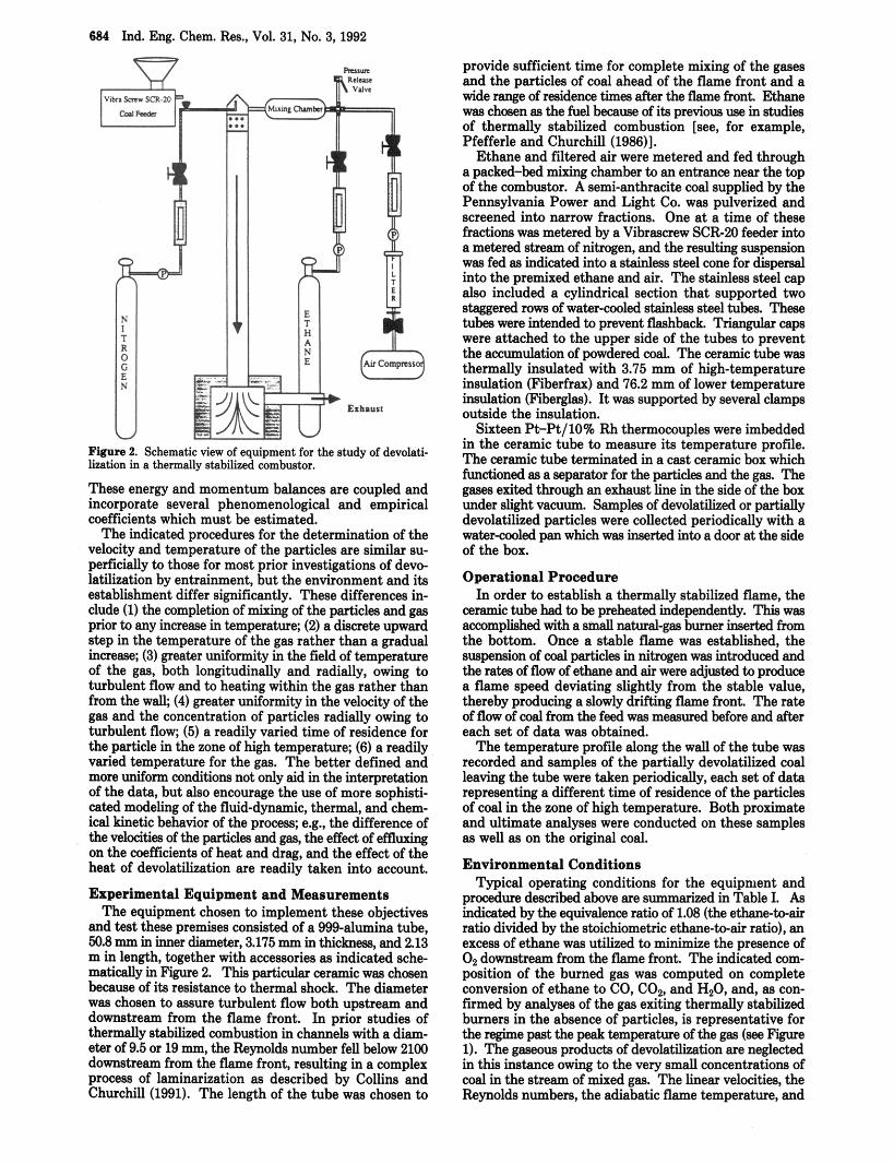
Fmre 2. Schematic view of equipment for the study of devolati- lization in a tbermdy stabilized combustor.
These energy and momentum balances are coupled and incorporate several phenomenological and empirical coefficients which must be estimated.
The indicated procedures for the determination of the velocity and temperature of the particles are similar su- perficially to those for most prior investigations of devo- latilization by entrainment, but the environment and its establishment differ significantly. These differences in- clude (1) the completion of mixing of the particles and gas prior to any increase in temperature; (2) a discrete upward step in the temperature of the gas rather than a gradual increase; (3) greater uniformity in the field of temperature of the gas, both longitudinally and radially, owing to turbulent flow and to heating within the gas rather than from the walk (4) greater uniformity in the velocity of the gas and the concentration of particles radially owing to turbulent flow; (5) a readily varied time of residence for the particle in the zone of high temperature; (6) a readily varied temperature for the gas. The better defined and more uniform conditions not only aid in the interpretation of the data, but also encourage the use of more sophisti- cated modeling of the fluid-dynamic, thermal, and chem- ical kinetic behavior of the process; e.g., the difference of the velocities of the particles and gas, the effect of effluxing on the coefficients of heat and drag, and the effect of the heat of devolatilization are readily taken into account.
Experimental Equipment and Measurements The equipment chosen to implement these objectives
and test these premises consisted of a 999-alumina tube, 50.8 mm in inner diameter, 3.175 mm in thickness, and 2.13 m in length, together with accessories as indicated sche matically in Figure 2. This particular ceramic was chosen because of its resistance to thermal shock. The diameter was chosen to assure turbulent flow both upstream and downstream from the flame front. In prior studies of thermally stabilized cornbustion in channels with a diam- eter of 9.5 or 19 mm, the Reynolds number fell below 2100 downstream from the flame front, resulting in a complex process of laminarization as described by Collins and Churchill (1991). The length of the tube was chosen to
provide sufficient time for complete mixing of the gases and the particles of coal ahead of the flame front and a wide range of residence times after the flame front. Ethane was chosen as the fuel because of its previous use in studies of thermally stabilized combustion [see, for example, Pfefferle and Churchill (1986)l.
Ethane and filtered air were metered and fed through a packed-bed mixing chamber to an entrance near the top of the combustor. A semi-anthracite coal supplied by the Pennsylvania Power and Light Co. was pulverized and screened into narrow fractions. One at a time of these fractions was metered by a Vihrascrew SCR20 feeder into a metered stream of nitrogen, and the resulting suspension was fed as indicated into a stainless steel cone for dispersal into the premixed ethane and air. The stainless steel cap also included a cylindrical section that supported two staggered row of water-cooled stainless steel tubes. These tubes were intended to prevent flashback. Triangular caps were attached to the upper side of the cubes to prevent the accumulation of powdered coal. The ceramic tube was thermally insulated with 3.75 mm of high-temperature insulation (Fiberfrax) and 76.2 mm of lower temperature insulation (Fiberelas). It was suooomd bv several C I ~ ~ O S _ _ outside the insufation.
Sixteen R-Pt/lO% Rh thermocouples were imbedded in the ceramic tube to measure its temperature orofile. The ceramic tube terminated in a cast &ramic box which functioned as a separator for the particles and the gas. The gases exited through an exhaust line in the side of the box under slight vacuum. Samples of d e v o l a t i i or partially devolatilized particles were collected periodically with a water-cooled pan which was inserted into a door at the side of the box.
Operational Procedure In order to establish a thermally Stabilized flame, the
ceramic tube had to be preheated independently. This was accomplished with a small natural-gas burner inserted from the bottom. Once a stable flame was established, the suspension of coal particles in nitrogen was in t rodud and the rates of flow of ethane and air were adjusted to produce a flame speed deviating slightly from the stable value, thereby producing a slowly drifting flame front. The rate of flow of coal from the feed was measured before and after each set of data was obtained.
The temperature profile along the wall of the tube was recorded and samples of the partially devolatilized coal leaving the tube were taken periodically, each set of data representing a different time of residence of the particles of coal in the zone of high temperature. Both proximate and ultimate analyses were conducted on these samples as well as on the original coal.
Environmental Conditions Typical operating conditions for the equipment and
procedure described above are summanzed ’ inTableI. ks indicated by the equivalence ratio of 1.08 (the ethanebair ratio divided by the stoichiometric ethane-to-air ratio), an excess of ethane was utilized to minimize the presence of O2 downstream from the flame front. The indicated com- position of the burned gas was computed on complete conversion of ethane to CO, CO,, and H20, and, as con- fmmed by analyses of the gas exiting thermally stabilized burners in the absence of particles, is representative for the regime past the peak temperature of the gas (see Figure 1). The gaseous products of devolatilization are neglected in this instance owing to the very small concentrations of coal in the stream of mixed gas. The linear velocities, the Reynolds numbers, the adiabatic flame temperature, and
Ind. Eng. Chem. Res., Vol. 31, No. 3, 1992 685
be determined as a function of time. Under the combined influence of gravity and the drag
of the stream of gas, the particles of coal, upstream from the flame front, accelerate rapidly to an asymptotic velocity slightly greater than that of the gas. Owing to ita expan- sion, the gas undergoes an essentially discrete increase in velocity across the flame front. The particles thereupon undergo a process similar to that ahead of the flame front; that is, they accelerate rapidly under that combined in- fluence of gravity and drag to another asymptotic velocity slightly greater than the new velocity of the gas.
The velocity of a particle, both ahead of and behind the flame front, is determined as a function of time by inte- grating a simple force-momentum balance, and the loca- tion of the particle is determined by a second integration. The limiting value for the latter integration is the time of residence in the zone of high temperature. The drag coefficient that occurs in the force-momentum balance is primarily a function of the Reynolds number for the particle, which is based on an effective diameter and the velocity difference between the particle and the gas. The effect of the level of turbulence of the stream of gas and the net effect of effluxing on the drag coefficient were estimated from correlations to be negligible for the con- ditions encountered in the present work. The process of analysis described so far can be designated as level I. It yields the extent of devolatilization as a function of the time of residence in a gas of constant temperature and composition.
If the particle is sufficiently small so that the internal variation in temperature is negligible, the rate of devola- tilization can instead be expressed in more fundamental terms as a function of the temperature of the particle and the extent of devolatilization. This description can be designated as level II. As indicated above, the temperature of the particle is determined as a function of time from a differential energy balance. The heat-transfer coefficient for convection between the particle and the gas depends slightly on the Reynolds number of the particle relative to the gas and on the Prandtl number of the gas, and even less on the rate of effluxing and the degree of turbulence in the stream of gas. The energy balance also incorporates radiative transfer between the particles and the wall, and the heat of devolatilization, which is highly uncertain, times the measured rate of devolatilization.
If the particle is sufficiently large so that the internal variations in temperature and in the extent of devolati- lization are significant, the energy balance becomes a partial differential equation in time and "radius". This description can be designated as level 111. Since a model for the rate of devolatilization must be postulated or de- termined by trial and error in order to describe the local behavior within the particle, such an analysis is somewhat empirical.
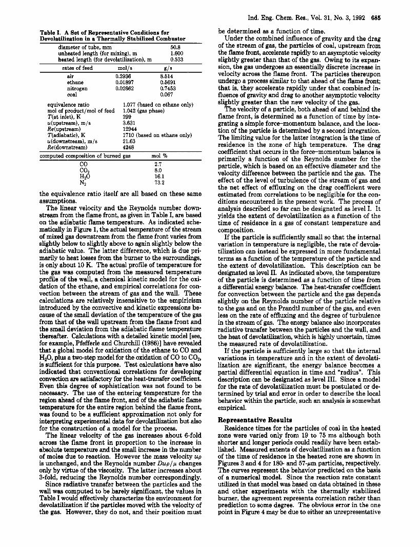
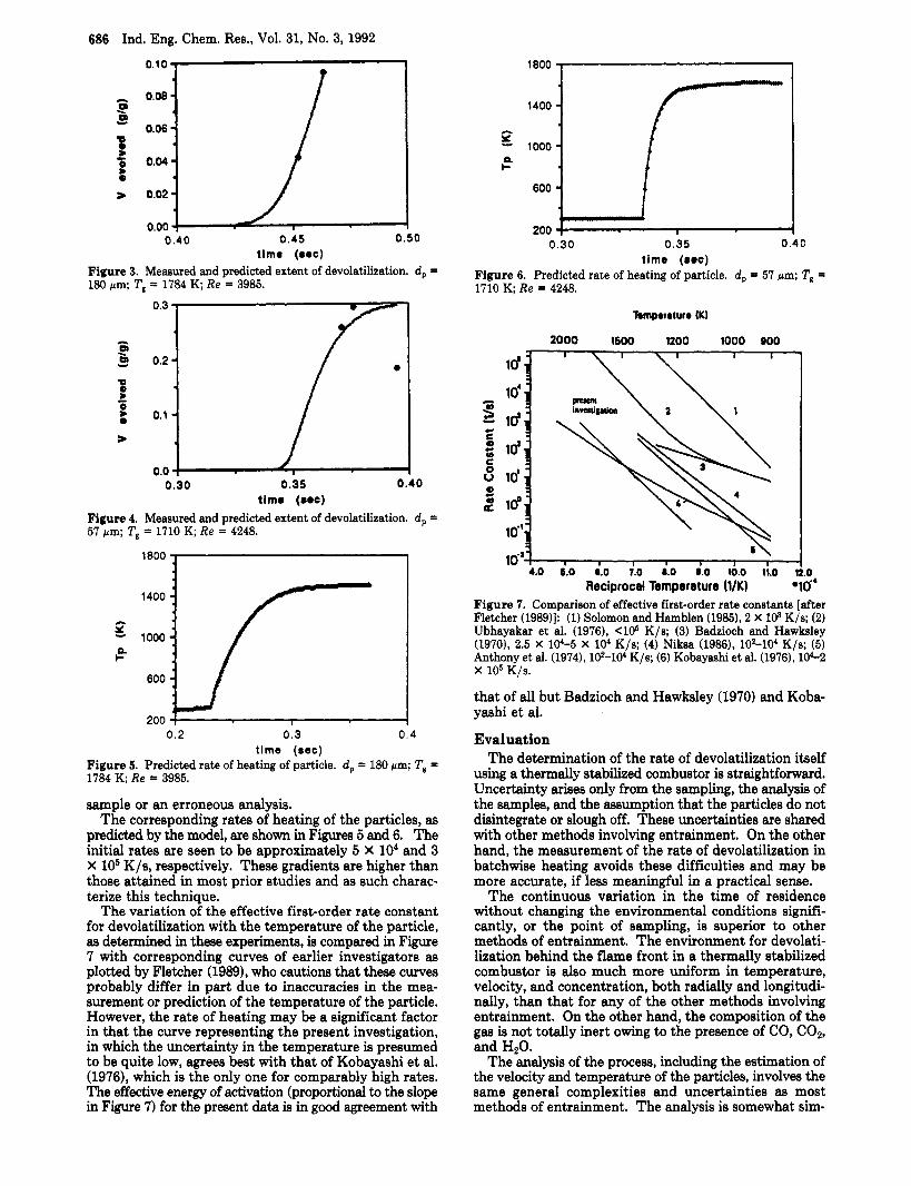
Representative Results Residence times for the particles of coal in the heated
zone were varied only from 19 to 75 ms although both shorter and longer periods could readily have been estab- lished. Measured extents of devolatilization as a function of the time of residence in the heated zone are shown in Figures 3 and 4 for 180- and 57-pm particles, respectively. The curves represent the behavior predicted on the basis of a numerical model. Since the reaction rate constant utilized in that model was based on data obtained in these and other experiments with the thermally stabilized burner, the agreement represents correlation rather than prediction to some degree. The obvious error in the one point in Figure 4 may be due to either an unrepresentative
Table I. A Set of Representative Conditions for Devolatilization in a Thermally Stabilized Combustor
diameter of tube, mm 50.8 unheated length (for mixing), m heated length (for devolatilization), m
1.600 0.533
rates of feed mol/s b?/S
air 0.2936 8.514 ethane 0.01897 0.5691 nitrogen 0.02662 0.7453 coal 0.067
equivalence ratio mol of product/mol of feed "(at inlet), K 299 u(upstream), m/s 3.631 Re(upstream) 12944 T(adiabatic), K u(downstream). m/s 21.63
1.077 (baaed on ethane only) 1.042 (gas phase)
1710 (based on ethane only)
Re(downstream) 4248 comDuted comoosition of burned gas mol %
2.7 8.0 16.1 73.2
the equivalence ratio itself are all based on these same assumptions.
The linear velocity and the Reynolds number down- stream from the flame front, as given in Table I, are based on the adiabatic flame temperature. As indicated sche- m a t i d y in Figure 1, the actual temperature of the stream of mixed gas downstream from the flame front varies from slightly below to slightly above to again slightly below the adiabatic value. The latter difference, which is due pri- marily to heat losses from the burner to the surroundings, is only about 10 K. The actual profile of temperature for the gas was computed from the measured temperature profile of the wall, a chemical kinetic model for the oxi- dation of the ethane, and empirical correlations for con- vection between the stream of gas and the wall. These calculations are relatively insensitive to the empiricism introduced by the convective and kinetic expressions be- cause of the small deviation of the temperature of the gas from that of the wall upstream from the flame front and the small deviation from the adiabatic flame temperature thereafter. Calculations with a detailed kinetic model [see, for example, Pfefferle and Churchill (1986)l have revealed that a global model for oxidation of the ethane to CO and HzO, plus a two-step model for the oxidation of CO to COz, is sufficient for this purpose. Test calculations have also indicated that conventional correlations for developing convection are satisfactory for the heabtransfer coefficient. Even this degree of sophistication was not found to be necessary. The use of the entering temperature for the region ahead of the flame front, and of the adiabatic flame temperature for the entire region behind the flame front, was found to be a sufficient approximation not only for interpreting experimental data for devolatilization but also for the construction of a model for the process.
The linear velocity of the gas increases about 6-fold across the flame front in proportion to the increase in absolute temperature and the small increase in the number of moles due to reaction. However the mass velocity up is unchanged, and the Reynolds number Dup/p changes only by virtue of the viscosity. The latter increases about 3-fold, reducing the Reynolds number correspondingly.
Since radiative transfer between the particles and the wall was computed to be barely significant, the values in Table I would effectively characterize the environment for devolatilization if the particles moved with the velocity of the gas. However, they do not, and their position must
686 Ind. Eng. Chem. Res., Vol. 31, No. 3, 1992
0.00 0.40 0 .45 0.50
timo (om) Figure 3. Measured and predicted extent of devolatilization. d , = 180 pm; Tg = 1784 K, Re = 3985.
0.0 0.30 0.35 0.40
tlmo ( o w ) Figure 4. Measured and predicted extent of devolatilization. d, = 57 pm; Tg = 1710 K; Re = 4248.
200 1 I I 0.2 0.3 0.4
time (sec) Figure 5. Predicted rate of heating of particle. d , = 180 pm; Tg = 1784 K; Re = 3985.
sample or an erroneous analysis. The corresponding rates of heating of the particles, as
predicted by the model, are shown in Figures 5 and 6. The initial rates are seen to be approximately 5 X lo4 and 3 X lo5 K/s, respectively. These gradienta are higher than those attained in most prior studies and as such charac- terize this technique.
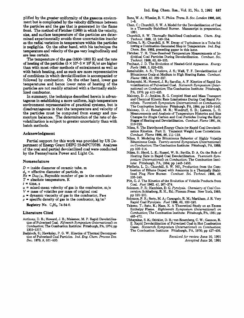
The variation of the effective first-order rate constant for devolatilization with the temperature of the particle, as determined in these experiments, is compared in Figure 7 with corresponding curves of earlier investigators as plotted by Fletcher (1989), who cautions that these curves probably differ in part due to inaccuracies in the mea- surement or prediction of the temperature of the particle. However, the rate of heating may be a significant factor in that the curve representing the present investigation, in which the uncertainty in the temperature is presumed to be quite low, agrees best with that of Kobayashi et al. (1976), which is the only one for comparably high rates. The effective energy of activation (proportional to the slope in Figure 7) for the present data is in good agreement with
1800 3
5 1000 n k-
600
200 0.30 0.35 0 . 4 0
time (aec) Figure 6. Predicted rate of heating of particle. d, = 57 pm; T8 = 1710 K; Re = 4248.
Tomporoturr (KI
2000 1600 1200 1000 BOO
1 I I 1 I I 1
4.0 6.0 0.0 7.0 B.0 B.0 10.0 11.0 12.0 Reciprocal Temperature (VK) *lo-'
Figure 7. Comparison of effective first-order rate constanta [after Fletcher (1989)) (1) Solomon and Hamblen (1985), 2 X 10³ K/s; (2) Ubhayakar et al. (1976), <lo6 K/s; (3) Badzioch and Hawksley (19701, 2.5 X lo4-5 X lo4 K/s; (4) Niksa (1986), l@-lO* K/s; (5) Anthony et al. (1974), lP-104 K/s; (6) Kobayashi et al. (1976), 10C2
that of all but Badzioch and Hawksley (1970) and Koba- yashi et al.
Evaluation The determination of the rate of devolatilization itself
using a thermally stabilized combustor is straightforward. Uncertainty arises only from the sampling, the analysis of the samples, and the assumption that the particles do not disintegrate or slough off. These uncertainties are shared with other methods involving entrainment. On the other hand, the measurement of the rate of devolatilization in batchwise heating avoids these difficulties and may be more accurate, if less meaningful in a practical sense.
The continuous variation in the time of residence without changing the environmental conditions signifi- cantly, or the point of sampling, is superior to other methods of entrainment. The environment for devolati- lization behind the flame front in a thermally stabilized combustor is also much more uniform in temperature, velocity, and concentration, both radially and longitudi- nally, than that for any of the other methods involving entrainment. On the other hand, the composition of the gas is not totally inert owing to the presence of CO, COz,
The analysis of the process, including the estimation of the velocity and temperature of the particles, involves the same general complexities and uncertainties as most methods of entrainment. The analysis is somewhat sim-
x 105 ~ / s .
and H20.
Ind. Eng. Chem. Res., Vol. 31, No. 3, 1992 687
Bone, W. A.; Wheeler, R. V. Philos. Trans. R. SOC. London 1906,2M, 1-8.
Chan, C.; Churchill, S. W. A Model for the Devolatilization of Coal in a Thermally Stabilized Burner. Manuscript in preparation, 1991.
Churchill. S. W. Thermallv Stabilized Combustion. Chem. Ena
plified by the greater uniformity of the gaseous environ- ment but is complicated by the velocity difference between the particles and the gas that is generated by the flame front. The method of Fletcher (1989) in which the velocity, size, and surface temperature of the particles are deter- mined experimentally avoids these uncertainties insofar as the radial variation in temperature within the particles is negligible. On the other hand, with his technique the temperature and velocity of the gas vary longitudinally and are less certain.
The temperature of the gas (1600-1800 K) and the rate of heating of the particles (5 X 10⁴-3 X 10⁵ K/s) are higher than with most other methods of entrainment as well as with batch heating, and as such are more representative of conditions in which devolatilization is accompanied or followed by combustion. On the other hand, lower gas temperatures and hence lower rates of heating of the particles are not readily attained with a thermally stabi- lized combustor.
In summary, the technique described herein is advan- tageous in establishing a more uniform, high-temperature environment representative of practical systems, but is disadvantageous in that the temperature and velocity of the particles must be computed from energy and mo- mentum balances. The determination of the rate of de- volatilization is subject to greater uncertainty than with batch methods.
Acknowledgment
Partial support for this work was provided by US De- partment of Energy Grant DEFG 22-84PC70789. Analyses of the coal and partial devolatilized coal were conducted by the Pennsylvania Power and Light Co.
Nomenclature D = inside diameter of ceramic tube, m d, = effective diameter of particle, m Re = Duplp, Reynolds number of gas in the combustor T = absolute temperature, K t = time, s u = mixed-mean velocity of gas in the combustor, m/s V = mass of volatile5 per mass of original coal p = dynamic viscosity of gas in the combustor, Pes p = specific density of gas in the combustor, kg/m3
Registry No. C2H6, 74-84-0.
Literature Cited Anthony, D. B.; Howard, J. B.; Meissner, M. P. Rapid Devolatiliza-
tion of Pulverized Coal. Fifteenth Symposium (International) on Combustion; The Combustion Institute Pittsburgh, PA, 1974; pp 1303-1317.
Badzioch, S.; Hawksley, P. G. W. Kinetics of Thermal Decomposi- tion of Pulverized Coal Particles. Ind. Eng. Chem. Process Des. Deu. 1970,9,521-530.
Technol. 1989, 12, 249-254. -
Colliins. L. R.: Churchill. S. W. Decav of Turbulence in a Tube fol- ~ .. ~..
lo&g a Combustion-Generated S b p in Temperature. Ind. Eng. Chem. Res. 1992, preceding paper in this issue.
Fletcher, T. H. Time-Resolved Temperature Measurements of In- dividual Coal Particles During Devolatilization. Combust. Sci. Technol. 1989,63,89-105.
Freihaut, J. D. The Evolution of Heated-Grid Apparatus. Energy Fuels 1989, 3, 625-635.
Jamaluddin, A. S.; Truelove, J. S.; Wall, T. F. Devolatilization of Bituminous Coals a t Medium to High Heating Rates. Combust. Flame 1986,63,329-337.
Kobayashi, H.; Howard, J. B.; Sarofim, A. F. Kinetics of Rapid De- volatilization of Pulverized Coal. Sixteenth Symposium (Inter- national) on Combustion; The Combustion Institute Pittsburgh, PA, 1976; pp 411-425.
Maloney, D. J.; Jenkins, R. G. Coupled Heat and Mass Transport and Chemical Kinetic Rate Limitations During Coal Rapid Py- rolysis. Twentieth Symposium (International) on Combustion; The Combustion Institute: Pittsburgh, PA, 1984; pp 1435-1443.
Maloney, D. J.; Esmail, M. R.; Woodruff, S. D.; Lawson, L. 0. Measurements and Analysis of Temperature Histories and Size Changes for Single Carbon and Coal Particles During the Early Stages of Heating and Devolatilization. Combust. Flame 1991,84, 210-220.
Niksa, S. The Distributed-Energy Chain for Rapid Coal Devolatili- zation Kinetics. Part 11. Transient Weight Loss Correlations. Combust. Flame 1986,66,111-119.
Niksa, S . Modeling the Bituminous Behavior of Highly Volatile Bituminous Coals. Twenty-second Symposium (International) on Combustion: The Combustion Institute: Pittsbureh. PA. 1988: - . . I
pp 105-114. Niksa, S.; Heyd, L. E.; Russel, W. B.; Saville, D. A. On the Role of
Heating Rate in RaDid Coal Devolatilization. Twentieth Svm- posiuk(Internatiok1) on Combustion; The Combustion Insti- tute: Pittsburgh, PA, 1984, pp 1445-1453.
Pfefferle, L. D.; Churchill, S. W. NO, Production from the Com- bustion of Ethane Doped with Ammonia in a Thermally Stabi- lized Plug Flow Burner. Combust. Sci. Technol. 1986, 49,
Pitt, G. J. The Kinetics of the Evolution of Volatile Products from Coal. Fuel 1962,41, 267-274.
Solomon, P. R.; Hamblen, D. G. Pyrolysis. Chemistry of Coal Con- version; Schlosberg, R. H., Ed.; Plenum Press: New York, 1985;
Solomon, P. R.; Serio, M. A.; Carangelo, R. M.; Markham, J. R. Very Rapid Coal Pyrolysis. Fuel 1986, 65, 182-193.
Takeno, T.; Sato, K.; Hase, K. A Theoretical Study on an Excess Enthalpy Flame. Eighteenth Symposium (International) on Combustion; The Combustion Institute: Pittsburgh, PA, 1981; pp 465-472.
Ubhayakar, S. K.; Stickler, D. B.; von Rosenberg, C. W.; Gannon, R. E. Rapid Devolatilization of Pulverized Coal in Hot Combustion Gases. Sixteenth Symposium (International) on Combustion; The Combustion Institute Pittsburgh, PA, 1976; pp 427-436.
Receiued for review June 10, 1991 Accepted June 26,1991
235-249.
pp 121-251.