Embed Size (px)
Citation preview
7-135
7-184 The validity of the Clausius inequality is to be demonstrated using a reversible and an irreversible heat engine operating between the same temperature limits. Analysis Consider two heat engines, one reversible and one irreversible, both operating between a high-temperature reservoir at TH and a low-temperature reservoir at TL. Both heat engines receive the same amount of heat, QH. The reversible heat engine rejects heat in the amount of QL, and the irreversible one in the amount of QL, irrev = QL + Qdiff, where Qdiff is a positive quantity since the irreversible heat engine produces less work. Noting that QH and QL are transferred at constant temperatures of TH and TL, respectively, the cyclic integral of δQ/T for the reversible and irreversible heat engine cycles become
011
rev=−=−=−=
∫∫∫∫∫L
L
H
HL
LH
HL
L
H
H
TQ
TQ
QT
QTT
QTQ
TQ
δδδδδ
since (QH/TH) = (QL/TL) for reversible cycles. Also,
0diffdiffirrev,
irrev<−=−−=−=
∫LLL
L
H
H
L
L
H
H
TQ
TQ
TQ
TQ
TQ
TQ
TQδ
since Qdiff is a positive quantity. Thus, 0≤
∫ T
Qδ .
Rev HE
QL ·
QH
Wnet, rev ·
·
QL, irrev ·
Irrev HE
QH
Wnet, irrev
·
TH
TL
7-185 The inner and outer surfaces of a window glass are maintained at specified temperatures. The amount of heat transfer through the glass and the amount of entropy generation within the glass in 5 h are to be determined Assumptions 1 Steady operating conditions exist since the surface temperatures of the glass remain constant at the specified values. 2 Thermal properties of the glass are constant. Analysis The amount of heat transfer over a period of 5 h is
Glass kJ 57,600=×=∆= )s 36005)(kJ/s 3.2(cond tQQ &
We take the glass to be the system, which is a closed system. Under steady conditions, the rate form of the entropy balance for the glass simplifies to
{
W/K0.287=→=+−
=+−
=∆=+−
glassgen,wallgen,
glassgen,outb,
out
inb,
in
entropy of change of Rate
0system
generation entropy of Rate
gen
mass andheat by ansferentropy trnet of Rate
outin
0K 276W 3200
K 283W 3200
0
0
SS
STQ
TQ
SSSS
&&
&&&
43421&&
43421&&
10°C 3°C
PROPRIETARY MATERIAL. © 2006 The McGraw-Hill Companies, Inc. Limited distribution permitted only to teachers and educators for course preparation. If you are a student using this Manual, you are using it without permission.
7-136
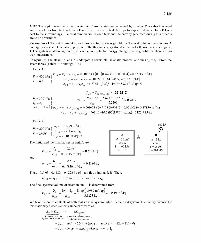
7-186 Two rigid tanks that contain water at different states are connected by a valve. The valve is opened and steam flows from tank A to tank B until the pressure in tank A drops to a specified value. Tank B loses heat to the surroundings. The final temperature in each tank and the entropy generated during this process are to be determined. Assumptions 1 Tank A is insulated, and thus heat transfer is negligible. 2 The water that remains in tank A undergoes a reversible adiabatic process. 3 The thermal energy stored in the tanks themselves is negligible. 4 The system is stationary and thus kinetic and potential energy changes are negligible. 5 There are no work interactions. Analysis (a) The steam in tank A undergoes a reversible, adiabatic process, and thus s2 = s1. From the steam tables (Tables A-4 through A-6),
( )( )( )( )
( )( )
( ) ( )( )( )( )
KkJ/kg 7.7100kJ/kg 2731.4
/kgm 1.1989
C250kPa 200
kJ/kg 2125.9kJ/kg 1982.17895.011.561/kgm 0.47850001073.060582.07895.0001073.0
7895.03200.5
6717.18717.5
mixture sat.
kPa 300
KkJ/kg 5.87171191.58.07765.1kJ/kg 2163.39.19488.022.604
/kgm 0.37015001084.046242.08.0001084.0
8.0kPa 400
,1
,1
3,1
1
1
,2,2
3,2,2
,2,2
kPa 300@sat,2
12
1
1,1
1,1
31,1
1
1
⋅===
°==
=+=+==−+=+=
=−
=−
=
°==
==
⋅=+=+==+=+=
=−+=+=
==
B
B
B
fgAfA
fgAfA
fg
fAA
A
fgfA
fgfA
fgfA
su
TP
uxuux
sss
x
TT
ssP
sxssuxuu
x
xP
v
vvv
vvv
:BTank
: ATank
C133.52
600 kJ
×B
m = 3 kg steam
T = 250°C P = 200 kPa
A V = 0.2 m3
steam P = 400 kPa
x = 0.8
The initial and the final masses in tank A are
and
kg 0.4180/kgm 0.47850
m 0.2
kg 0.5403/kgm 0.37015
m 0.2
3
3
,2,2
3
3
,1,1
===
===
A
AA
A
AA
m
m
v
V
v
V
Thus, 0.5403 - 0.4180 = 0.1223 kg of mass flows into tank B. Then, kg 3.12231223.031223.0,1,2 =+=+= BB mm
The final specific volume of steam in tank B is determined from
( ) ( )( )
/kgm 1.1519kg 3.1223
/kgm 1.1989kg 3 33
,2
11
,2,2 ====
B
B
B
BB m
mm
vVv
We take the entire contents of both tanks as the system, which is a closed system. The energy balance for this stationary closed system can be expressed as
( ) ( )BA
BA
umumumumQWUUUQ
EEE
11221122out
out
energies etc. potential, kinetic, internal,in Change
system
mass and work,heat,by nsferenergy traNet
outin
0)=PE=KE (since )()(−+−=−
=∆+∆=∆=−
∆=−4342143421
PROPRIETARY MATERIAL. © 2006 The McGraw-Hill Companies, Inc. Limited distribution permitted only to teachers and educators for course preparation. If you are a student using this Manual, you are using it without permission.
7-137
Substituting,
( )( ) ( )( ){ } ( ) ( )( ){ }
kJ/kg 2522.04.273131223.33.21635403.09.2125418.0600
,2
,2
=−+−=−
B
B
uu
Thus,
KkJ/kg 7.2274kJ/kg 2522.0
/kgm 1.1519
,2
,2
,2
3,2
⋅=°=
=
=
B
B
B
B
sT
u
v C113.2
(b) The total entropy generation during this process is determined by applying the entropy balance on an extended system that includes both tanks and their immediate surroundings so that the boundary temperature of the extended system is the temperature of the surroundings at all times. It gives
{
BAgensurrb,
out
entropyin Change
system
generationEntropy
gen
mass andheat by ansferentropy trNet
outin
SSSTQ
SSSS
∆+∆=+−
∆=+−4342143421
Rearranging and substituting, the total entropy generated during this process is determined to be
( ) ( )
( )( ) ( )( ){ } ( )( ) ( )( ){ } kJ/K 0.916=
+−+−=
+−+−=+∆+∆=
K 273kJ 600
7100.732274.71223.38717.55403.08717.5418.0
surrb,
out11221122
surrb,
outgen T
Qsmsmsmsm
TQ
SSS BABA
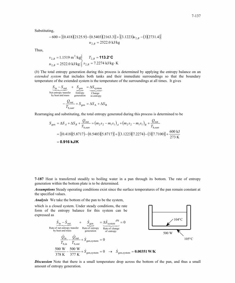
7-187 Heat is transferred steadily to boiling water in a pan through its bottom. The rate of entropy generation within the bottom plate is to be determined. Assumptions Steady operating conditions exist since the surface temperatures of the pan remain constant at the specified values. Analysis We take the bottom of the pan to be the system, which is a closed system. Under steady conditions, the rate form of the entropy balance for this system can be expressed as
{
W/K0.00351=→=+−
=+−
=∆=+−
systemgen,systemgen,
systemgen,outb,
out
inb,
in
entropy of change of Rate
0system
generation entropy of Rate
gen
mass andheat by ansferentropy trnet of Rate
outin
0K 377W 500
K 378W 500
0
0
SS
STQ
TQ
SSSS
&&
&&&
43421&&
43421&&
500 W
104°C
105°C
Discussion Note that there is a small temperature drop across the bottom of the pan, and thus a small amount of entropy generation.
PROPRIETARY MATERIAL. © 2006 The McGraw-Hill Companies, Inc. Limited distribution permitted only to teachers and educators for course preparation. If you are a student using this Manual, you are using it without permission.
7-138
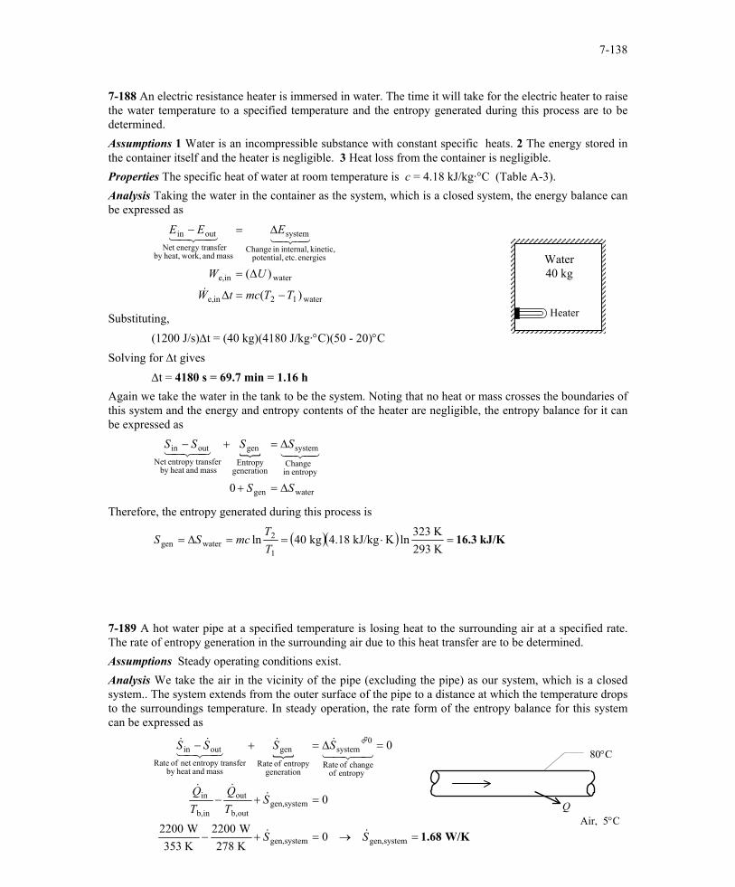
7-188 An electric resistance heater is immersed in water. The time it will take for the electric heater to raise the water temperature to a specified temperature and the entropy generated during this process are to be determined. Assumptions 1 Water is an incompressible substance with constant specific heats. 2 The energy stored in the container itself and the heater is negligible. 3 Heat loss from the container is negligible. Properties The specific heat of water at room temperature is c = 4.18 kJ/kg·°C (Table A-3). Analysis Taking the water in the container as the system, which is a closed system, the energy balance can be expressed as
water12ine,
waterine,
energies etc. potential, kinetic, internal,in Change
system
mass and work,heat,by nsferenergy traNet
outin
)(
)(
TTmctW
UW
EEE
−=∆
∆=
∆=−
&
4342143421
Heater
Water 40 kg
Substituting, (1200 J/s)∆t = (40 kg)(4180 J/kg·°C)(50 - 20)°C Solving for ∆t gives ∆t = 4180 s = 69.7 min = 1.16 h Again we take the water in the tank to be the system. Noting that no heat or mass crosses the boundaries of this system and the energy and entropy contents of the heater are negligible, the entropy balance for it can be expressed as
{
watergen
entropyin Change
system
generationEntropy
gen
mass andheat by ansferentropy trNet
outin
0 SS
SSSS
∆=+
∆=+−4342143421
Therefore, the entropy generated during this process is
( )( ) kJ/K 16.3=⋅==∆=K 293K 323
ln KkJ/kg 4.18kg 40ln1
2watergen T
TmcSS
7-189 A hot water pipe at a specified temperature is losing heat to the surrounding air at a specified rate. The rate of entropy generation in the surrounding air due to this heat transfer are to be determined. Assumptions Steady operating conditions exist. Analysis We take the air in the vicinity of the pipe (excluding the pipe) as our system, which is a closed system.. The system extends from the outer surface of the pipe to a distance at which the temperature drops to the surroundings temperature. In steady operation, the rate form of the entropy balance for this system can be expressed as
{
W/K 1.68=→=+−
=+−
=∆=+−
systemgen,systemgen,
systemgen,outb,
out
inb,
in
entropy of change of Rate
0system
generation entropy of Rate
gen
mass andheat by ansferentropy trnet of Rate
outin
0K 278W 2200
K 353W 2200
0
0
SS
STQ
TQ
SSSS
&&
&&&
43421&&
43421&&
80°C
Q Air, 5°C
PROPRIETARY MATERIAL. © 2006 The McGraw-Hill Companies, Inc. Limited distribution permitted only to teachers and educators for course preparation. If you are a student using this Manual, you are using it without permission.
7-139
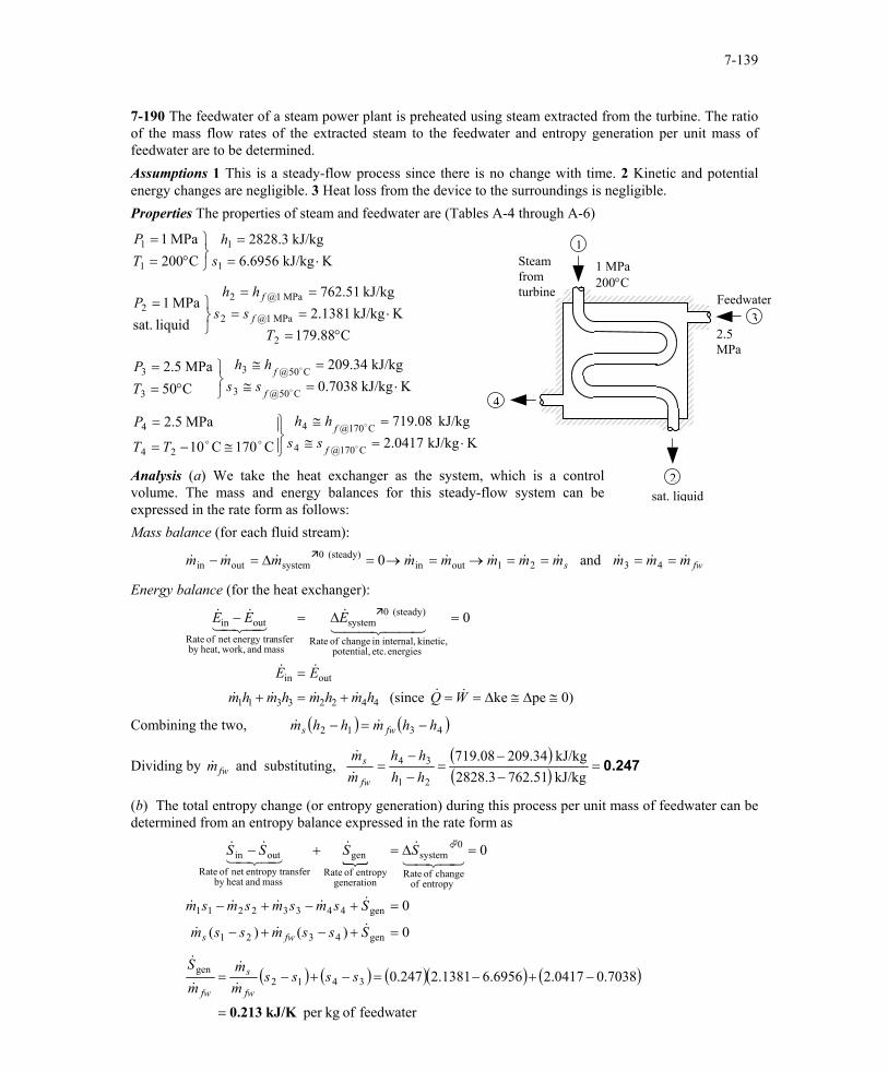
7-190 The feedwater of a steam power plant is preheated using steam extracted from the turbine. The ratio of the mass flow rates of the extracted steam to the feedwater and entropy generation per unit mass of feedwater are to be determined. Assumptions 1 This is a steady-flow process since there is no change with time. 2 Kinetic and potential energy changes are negligible. 3 Heat loss from the device to the surroundings is negligible. Properties The properties of steam and feedwater are (Tables A-4 through A-6)
KkJ/kg 2.0417kJ/kg 719.08
C170C10
MPa 2.5
KkJ/kg 0.7038kJ/kg 209.34
C50MPa 2.5
C179.88KkJ/kg 2.1381
kJ/kg 762.51
liquid sat.MPa 1
KkJ/kg 6.6956kJ/kg 2828.3
C200MPa 1
C170@4
C170@4
24
4
C50@3
C50@3
3
3
2
MPa 1@2
MPa 1@22
1
1
1
1
⋅=≅=≅
≅−=
=
⋅=≅=≅
°==
°=⋅==
==
=
⋅==
°==
o
o
o
o
oof
f
f
f
f
f
sshh
TT
P
sshh
TP
Tss
hhP
sh
TP
Analysis (a) We take the heat exchanger as the system, which is a control volume. The mass and energy balances for this steady-flow system can be expressed in the rate form as follows:
2.5 MPa
Feedwater
1 MPa 200°C
Steam from turbine
4
3
2
1
sat. liquid
Mass balance (for each fluid stream):
fws mmmmmmmmmmm &&&&&&&&&&& ====→=→=∆=− 4321outin(steady) 0
systemoutin and 0
Energy balance (for the heat exchanger):
0)peke (since
0
44223311
outin
energies etc. potential, kinetic, internal,in change of Rate
(steady) 0system
mass and work,heat,by nsferenergy tranet of Rate
outin
≅∆≅∆==+=+
=
=∆=−
WQhmhmhmhm
EE
EEE
&&&&&&
&&
44 344 21&
43421&&
Combining the two, ( ) ( )4312 hhmhhm fws −=− &&
Dividing by and substituting, &mfw( )( ) 0.247=
−−
=−−
=kJ/kg 762.512828.3kJ/kg 209.34719.08
21
34
hhhh
mm
fw
s
&
&
(b) The total entropy change (or entropy generation) during this process per unit mass of feedwater can be determined from an entropy balance expressed in the rate form as
{
0)()(
0
0
gen4321
gen44332211
entropy of change of Rate
0system
generation entropy of Rate
gen
mass andheat by ansferentropy trnet of Rate
outin
=+−+−
=+−+−
=∆=+−
Sssmssm
Ssmsmsmsm
SSSS
fws&&&
&&&&&
43421&&
43421&&
( ) ( ) ( )( ) (
feedwater of kgper
7038.00417.26956.61381.2247.03412gen
kJ/K 213.0=
−+−=−+−= ssssmm
mS
fw
s
fw &
&
&
&)
PROPRIETARY MATERIAL. © 2006 The McGraw-Hill Companies, Inc. Limited distribution permitted only to teachers and educators for course preparation. If you are a student using this Manual, you are using it without permission.
7-140
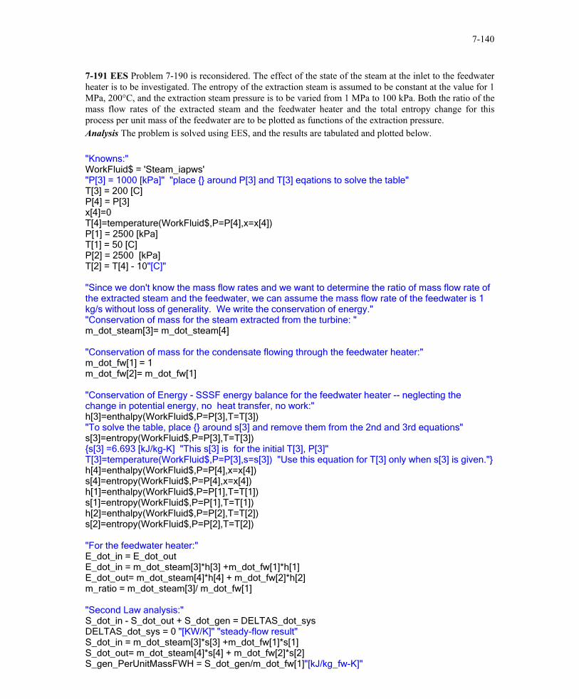
7-191 EES Problem 7-190 is reconsidered. The effect of the state of the steam at the inlet to the feedwater heater is to be investigated. The entropy of the extraction steam is assumed to be constant at the value for 1 MPa, 200°C, and the extraction steam pressure is to be varied from 1 MPa to 100 kPa. Both the ratio of the mass flow rates of the extracted steam and the feedwater heater and the total entropy change for this process per unit mass of the feedwater are to be plotted as functions of the extraction pressure. Analysis The problem is solved using EES, and the results are tabulated and plotted below. "Knowns:" WorkFluid$ = 'Steam_iapws' "P[3] = 1000 [kPa]" "place {} around P[3] and T[3] eqations to solve the table" T[3] = 200 [C] P[4] = P[3] x[4]=0 T[4]=temperature(WorkFluid$,P=P[4],x=x[4]) P[1] = 2500 [kPa] T[1] = 50 [C] P[2] = 2500 [kPa] T[2] = T[4] - 10"[C]" "Since we don't know the mass flow rates and we want to determine the ratio of mass flow rate of the extracted steam and the feedwater, we can assume the mass flow rate of the feedwater is 1 kg/s without loss of generality. We write the conservation of energy." "Conservation of mass for the steam extracted from the turbine: " m_dot_steam[3]= m_dot_steam[4] "Conservation of mass for the condensate flowing through the feedwater heater:" m_dot_fw[1] = 1 m_dot_fw[2]= m_dot_fw[1] "Conservation of Energy - SSSF energy balance for the feedwater heater -- neglecting the change in potential energy, no heat transfer, no work:" h[3]=enthalpy(WorkFluid$,P=P[3],T=T[3]) "To solve the table, place {} around s[3] and remove them from the 2nd and 3rd equations" s[3]=entropy(WorkFluid$,P=P[3],T=T[3]) {s[3] =6.693 [kJ/kg-K] "This s[3] is for the initial T[3], P[3]" T[3]=temperature(WorkFluid$,P=P[3],s=s[3]) "Use this equation for T[3] only when s[3] is given."} h[4]=enthalpy(WorkFluid$,P=P[4],x=x[4]) s[4]=entropy(WorkFluid$,P=P[4],x=x[4]) h[1]=enthalpy(WorkFluid$,P=P[1],T=T[1]) s[1]=entropy(WorkFluid$,P=P[1],T=T[1]) h[2]=enthalpy(WorkFluid$,P=P[2],T=T[2]) s[2]=entropy(WorkFluid$,P=P[2],T=T[2]) "For the feedwater heater:" E_dot_in = E_dot_out E_dot_in = m_dot_steam[3]*h[3] +m_dot_fw[1]*h[1] E_dot_out= m_dot_steam[4]*h[4] + m_dot_fw[2]*h[2] m_ratio = m_dot_steam[3]/ m_dot_fw[1] "Second Law analysis:" S_dot_in - S_dot_out + S_dot_gen = DELTAS_dot_sys DELTAS_dot_sys = 0 "[KW/K]" "steady-flow result" S_dot_in = m_dot_steam[3]*s[3] +m_dot_fw[1]*s[1] S_dot_out= m_dot_steam[4]*s[4] + m_dot_fw[2]*s[2] S_gen_PerUnitMassFWH = S_dot_gen/m_dot_fw[1]"[kJ/kg_fw-K]"
PROPRIETARY MATERIAL. © 2006 The McGraw-Hill Companies, Inc. Limited distribution permitted only to teachers and educators for course preparation. If you are a student using this Manual, you are using it without permission.
7-141
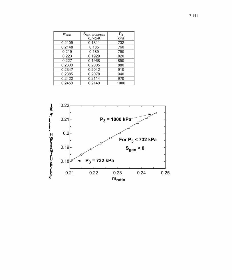
mratio Sgen,PerUnitMass
[kJ/kg-K] P3
[kPa] 0.2109 0.1811 732 0.2148 0.185 760 0.219 0.189 790 0.223 0.1929 820 0.227 0.1968 850
0.2309 0.2005 880 0.2347 0.2042 910 0.2385 0.2078 940 0.2422 0.2114 970 0.2459 0.2149 1000
0.21 0.22 0.23 0.24 0.25
0.18
0.19
0.2
0.21
0.22
mratioSgen,PerUnitMassFWH
[kJ/kgfw
-K]
P3 = 732 kPa
P3 = 1000 kPa
For P3 < 732 kPa
Sgen < 0
PROPRIETARY MATERIAL. © 2006 The McGraw-Hill Companies, Inc. Limited distribution permitted only to teachers and educators for course preparation. If you are a student using this Manual, you are using it without permission.
7-142
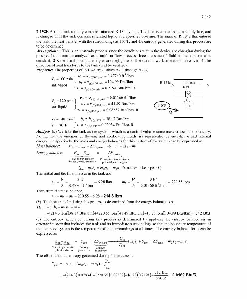
7-192E A rigid tank initially contains saturated R-134a vapor. The tank is connected to a supply line, and is charged until the tank contains saturated liquid at a specified pressure. The mass of R-134a that entered the tank, the heat transfer with the surroundings at 110°F, and the entropy generated during this process are to be determined. Assumptions 1 This is an unsteady process since the conditions within the device are changing during the process, but it can be analyzed as a uniform-flow process since the state of fluid at the inlet remains constant. 2 Kinetic and potential energies are negligible. 3 There are no work interactions involved. 4 The direction of heat transfer is to the tank (will be verified). Properties The properties of R-134a are (Tables A-11 through A-13)
RBtu/lbm 0.07934Btu/lbm 38.17
F80psia 140
RBtu/lbm 0.08589Btu/lbm 41.49
/lbmft 0.01360
liquid sat.psia 120
RBtu/lbm 0.2198Btu/lbm 104.99
/lbmft 0.47760
vapor sat.psia 100
F80@
F80@
psia 120@2
psia 120@2
3psia 120@2
2
psia 100@1
psia 100@1
3psia 100@1
1
⋅=≅=≅
°==
⋅======
=
⋅======
=
°
°
fi
fi
i
i
f
f
f
g
g
g
sshh
TP
ssuu
P
ssuu
P
vv
vv
110°F
Q
R-134a
R-134a 3 ft3
140 psia 80°F
Analysis (a) We take the tank as the system, which is a control volume since mass crosses the boundary. Noting that the energies of flowing and nonflowing fluids are represented by enthalpy h and internal energy u, respectively, the mass and energy balances for this uniform-flow system can be expressed as Mass balance: 12systemoutin mmmmmm i −=→∆=−
Energy balance:
)0peke (since 1122in
energies etc. potential, kinetic, internal,in Change
system
mass and work,heat,by nsferenergy traNet
outin
≅≅≅−=+
∆=−
WumumhmQ
EEE
ii
4342143421
The initial and the final masses in the tank are
lbm 220.55/lbmft 0.01360
ft 3 lbm 28.6/lbmft 0.4776
ft 33
3
223
3
11 ======
vV
vV mm
Then from the mass balance, lbm 214.3=−=−= 28.655.22012 mmmi (b) The heat transfer during this process is determined from the energy balance to be
( )( ) ( )( ) ( )( ) Btu 312=−+−=−+−=
Btu/lbm 104.99lbm 6.28Btu/lbm 41.49lbm 220.55Btu/lbm 38.17lbm 214.31122in umumhmQ ii
(c) The entropy generated during this process is determined by applying the entropy balance on an extended system that includes the tank and its immediate surroundings so that the boundary temperature of the extended system is the temperature of the surroundings at all times. The entropy balance for it can be expressed as
{ 1122tankgen
inb,
in
entropyin Change
system
generationEntropy
gen
mass andheat by ansferentropy trNet
outin smsmSSsmTQ
SSSS ii −=∆=++→∆=+−4342143421
Therefore, the total entropy generated during this process is
( )( ) ( )( ) ( )( ) Btu/R 0.0169=−−+−=
−−+−=
R 570Btu 312
2198.028.608589.055.22007934.03.214
)(inb,
in1122gen T
QsmsmsmS ii
PROPRIETARY MATERIAL. © 2006 The McGraw-Hill Companies, Inc. Limited distribution permitted only to teachers and educators for course preparation. If you are a student using this Manual, you are using it without permission.
7-143
7-193 It is to be shown that for thermal energy reservoirs, the entropy change relation ∆ reduces to as .
)/ln( 12 TTmcS =∆S Q T= / T T2 1 →
Analysis Consider a thermal energy reservoir of mass m, specific heat c, and initial temperature T1. Now heat, in the amount of Q, is transferred to this reservoir. The first law and the entropy change relations for this reservoir can be written as
and
( )
( )12
12
1
2
1212
/lnln
TTTT
QTT
mcS
TTQ
mcTTmcQ
−==∆
−=→−=
Thermal energy reservoir
m, c, T
Q
Taking the limit as T2 → T1 by applying the L'Hospital's rule,
∆S QT Q
T= =
11
1
1
/
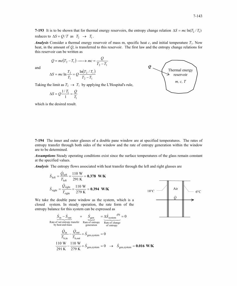
which is the desired result. 7-194 The inner and outer glasses of a double pane window are at specified temperatures. The rates of entropy transfer through both sides of the window and the rate of entropy generation within the window are to be determined. Assumptions Steady operating conditions exist since the surface temperatures of the glass remain constant at the specified values. Analysis The entropy flows associated with heat transfer through the left and right glasses are
W/K 0.394
W/K 0.378
===
===
K 279W 110
K 291W 110
right
rightright
left
leftleft
TQ
S
TQ
S
&&
&&
We take the double pane window as the system, which is a closed system. In steady operation, the rate form of the entropy balance for this system can be expressed as
{
W/K 0.016=→=+−
=+−
=∆=+−
systemgen,systemgen,
systemgen,outb,
out
inb,
in
entropy of change of Rate
0system
generation entropy of Rate
gen
mass andheat by ansferentropy trnet of Rate
outin
0K 279W 110
K 291W 110
0
0
SS
STQ
TQ
SSSS
&&
&&&
43421&&
43421&&
Air
Q ·18°C 6°C
PROPRIETARY MATERIAL. © 2006 The McGraw-Hill Companies, Inc. Limited distribution permitted only to teachers and educators for course preparation. If you are a student using this Manual, you are using it without permission.
7-144
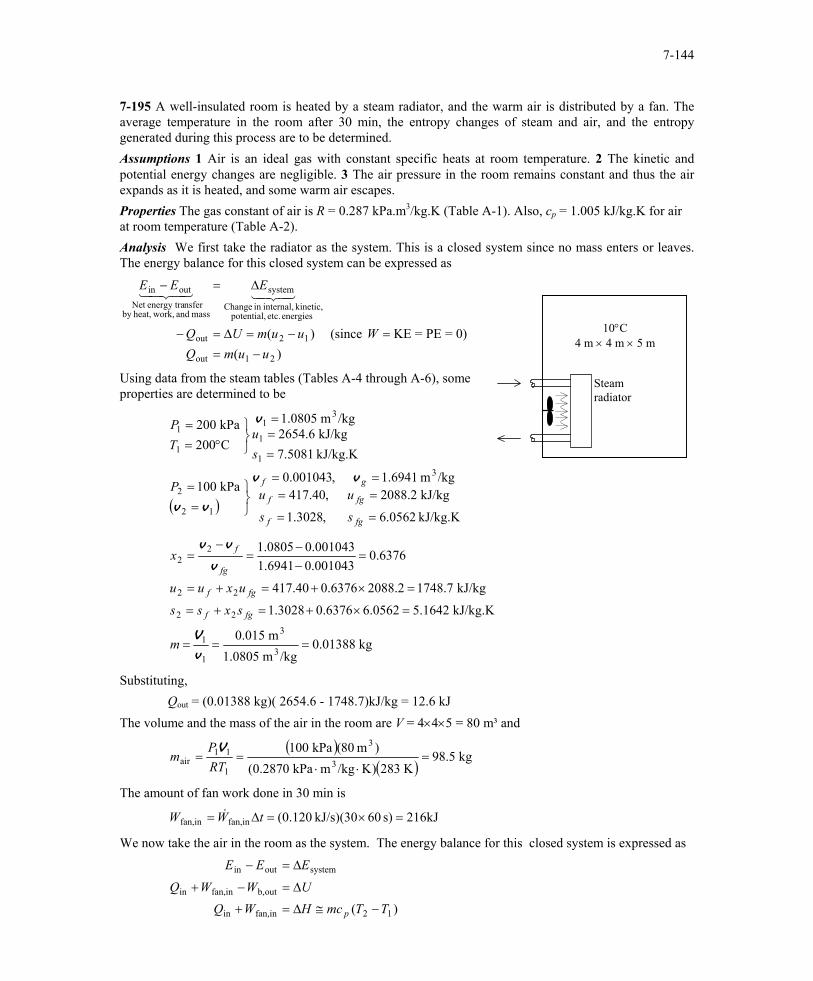
7-195 A well-insulated room is heated by a steam radiator, and the warm air is distributed by a fan. The average temperature in the room after 30 min, the entropy changes of steam and air, and the entropy generated during this process are to be determined. Assumptions 1 Air is an ideal gas with constant specific heats at room temperature. 2 The kinetic and potential energy changes are negligible. 3 The air pressure in the room remains constant and thus the air expands as it is heated, and some warm air escapes. Properties The gas constant of air is R = 0.287 kPa.m3/kg.K (Table A-1). Also, cp = 1.005 kJ/kg.K for air at room temperature (Table A-2). Analysis We first take the radiator as the system. This is a closed system since no mass enters or leaves. The energy balance for this closed system can be expressed as
)(0)=PE=KE (since )(
21out
12out
energies etc. potential, kinetic, internal,in Change
system
mass and work,heat,by nsferenergy traNet
outin
uumQWuumUQ
EEE
−==−=∆=−
∆=−4342143421
10°C 4 m × 4 m × 5 m
Steam radiator
Using data from the steam tables (Tables A-4 through A-6), some properties are determined to be
( )kJ/kg.K 0562.6
kJ/kg 2088.2
,3028.1
,40.417/kgm 1.6941,001043.0
kPa 100
kJ/kg.K 5081.7kJ/kg 2654.6
/kgm 1.0805
C200kPa 200
3
12
2
1
1
31
1
1
=
=
=
===
==
===
°==
fg
fg
f
f
gf
s
u
s
uP
su
TP
vv
vv
v
kg 0.01388/kgm 1.0805
m 0.015
kJ/kg.K 1642.50562.60.63763028.1
kJ/kg 1748.72088.20.6376417.40
6376.0001043.06941.1001043.00805.1
3
3
1
1
22
22
22
===
=×+=+=
=×+=+=
=−−
=−
=
v
V
v
vv
m
sxss
uxuu
x
fgf
fgf
fg
f
Substituting, Qout = (0.01388 kg)( 2654.6 - 1748.7)kJ/kg = 12.6 kJ The volume and the mass of the air in the room are V = 4×4×5 = 80 m³ and
( )
( )kg 98.5
K 283)K/kgmkPa 0.2870()m 80(kPa 100
3
3
1
11air =
⋅⋅==
RTP
mV
The amount of fan work done in 30 min is
kJ216s) 60kJ/s)(30 120.0(infan,infan, =×=∆= tWW &
We now take the air in the room as the system. The energy balance for this closed system is expressed as
)( 12infan,in
outb,infan,in
systemoutin
TTmcHWQUWWQ
EEE
p −≅∆=+
∆=−+
∆=−
PROPRIETARY MATERIAL. © 2006 The McGraw-Hill Companies, Inc. Limited distribution permitted only to teachers and educators for course preparation. If you are a student using this Manual, you are using it without permission.

7-145
since the boundary work and ∆U combine into ∆H for a constant pressure expansion or compression process. Substituting, (12.6 kJ) + (216 kJ) = (98.5 kg)(1.005 kJ/kg°C)(T2 - 10)°C which yields T2 = 12.3°C Therefore, the air temperature in the room rises from 10°C to 12.3°C in 30 min. (b) The entropy change of the steam is ( ) ( )( ) kJ/K 0.0325−=⋅−=−=∆ KkJ/kg7.50815.1642kg 0.0138812steam ssmS
(c) Noting that air expands at constant pressure, the entropy change of the air in the room is
( )( ) kJ/K 0.8013=⋅=−=∆K 283K 285.3
ln KkJ/kg 1.005kg 98.5lnln0
1
2
1
2air P
PmR
TT
mcS p
(d) We take the air in the room (including the steam radiator) as our system, which is a closed system. Noting that no heat or mass crosses the boundaries of this system, the entropy balance for it can be expressed as
{
airsteamgen
entropyin Change
system
generationEntropy
gen
mass andheat by ansferentropy trNet
outin
0 SSS
SSSS
∆+∆=+
∆=+−4342143421
Substituting, the entropy generated during this process is determined to be kJ/K 0.7688=+−=∆+∆= 8013.00325.0airsteamgen SSS
PROPRIETARY MATERIAL. © 2006 The McGraw-Hill Companies, Inc. Limited distribution permitted only to teachers and educators for course preparation. If you are a student using this Manual, you are using it without permission.
7-146
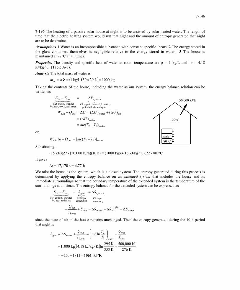
7-196 The heating of a passive solar house at night is to be assisted by solar heated water. The length of time that the electric heating system would run that night and the amount of entropy generated that night are to be determined. Assumptions 1 Water is an incompressible substance with constant specific heats. 2 The energy stored in the glass containers themselves is negligible relative to the energy stored in water. 3 The house is maintained at 22°C at all times. Properties The density and specific heat of water at room temperature are ρ = 1 kg/L and c = 4.18 kJ/kg·°C (Table A-3). Analysis The total mass of water is ( )( ) kg 1000L 2050kg/L 1 =×== Vρwm
Taking the contents of the house, including the water as our system, the energy balance relation can be written as
water12
water
airwateroutine,
energies etc. potential, kinetic, internal,in Change
system
mass and work,heat,by nsferenergy traNet
outin
)()(
)()(
TTmcU
UUUQW
EEE
−=∆=
∆+∆=∆=−
∆=−4342143421
80°C water
50,000 kJ/h
22°C
or,
water12outine, )]([ TTmcQtW −=−∆&
Substituting, (15 kJ/s)∆t - (50,000 kJ/h)(10 h) = (1000 kg)(4.18 kJ/kg·°C)(22 - 80)°C
It gives ∆t = 17,170 s = 4.77 h We take the house as the system, which is a closed system. The entropy generated during this process is determined by applying the entropy balance on an extended system that includes the house and its immediate surroundings so that the boundary temperature of the extended system is the temperature of the surroundings at all times. The entropy balance for the extended system can be expressed as
{
water0
airwatergenoutb,
out
entropyin Change
system
generationEntropy
gen
mass andheat by ansferentropy trNet
outin
SSSSTQ
SSSS
∆=∆+∆=+−
∆=+−4342143421
since the state of air in the house remains unchanged. Then the entropy generated during the 10-h period that night is
( )( )
kJ/K 1061=+−=
+⋅=
+
=+∆=
1811750K 276
kJ 500,000K 353K 295
lnKkJ/kg 4.18kg 1000
lnsurr
out
water1
2
outb,
outwatergen T
QTT
mcTQ
SS
PROPRIETARY MATERIAL. © 2006 The McGraw-Hill Companies, Inc. Limited distribution permitted only to teachers and educators for course preparation. If you are a student using this Manual, you are using it without permission.
7-147
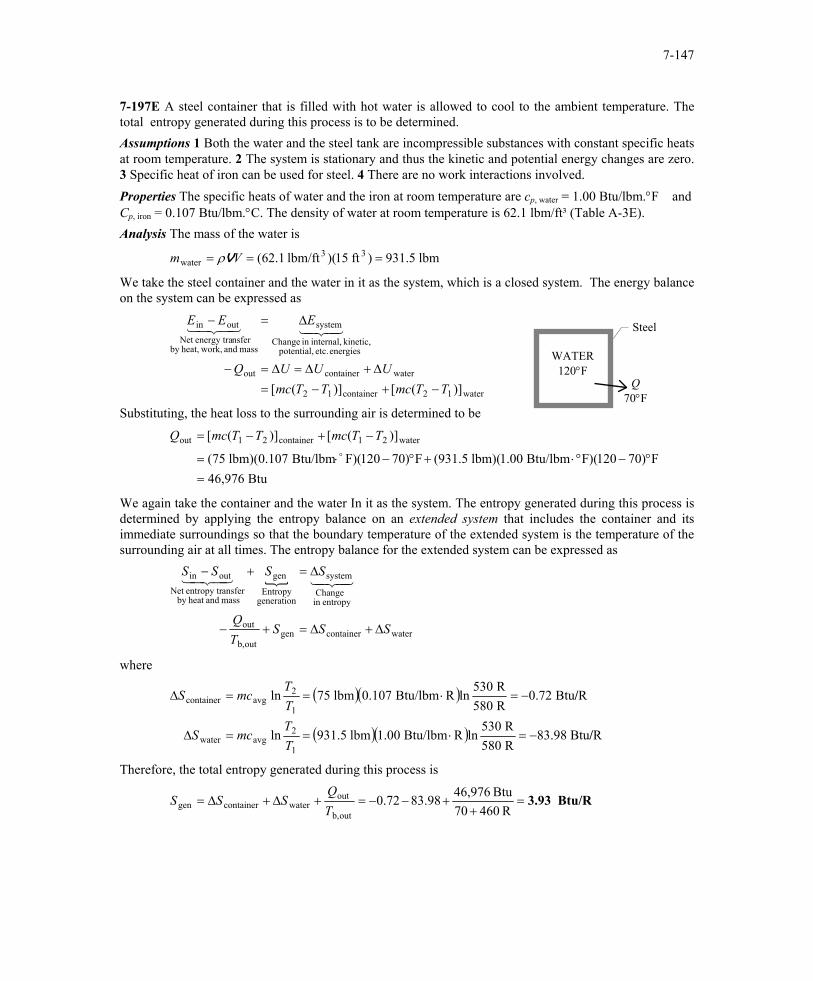
7-197E A steel container that is filled with hot water is allowed to cool to the ambient temperature. The total entropy generated during this process is to be determined. Assumptions 1 Both the water and the steel tank are incompressible substances with constant specific heats at room temperature. 2 The system is stationary and thus the kinetic and potential energy changes are zero. 3 Specific heat of iron can be used for steel. 4 There are no work interactions involved. Properties The specific heats of water and the iron at room temperature are cp, water = 1.00 Btu/lbm.°F and Cp, iron = 0.107 Btu/lbm.°C. The density of water at room temperature is 62.1 lbm/ft³ (Table A-3E). Analysis The mass of the water is
lbm 931.5)ft 15)(lbm/ft 62.1( 33water === Vm Vρ
We take the steel container and the water in it as the system, which is a closed system. The energy balance on the system can be expressed as
water12container12
watercontainerout
energies etc. potential, kinetic, internal,in Change
system
mass and work,heat,by nsferenergy traNet
outin
)]([)]([ TTmcTTmcUUUQ
EEE
−+−=∆+∆=∆=−
∆=−4342143421
Q 70°F
Steel
WATER 120°F
Substituting, the heat loss to the surrounding air is determined to be
Btu 46,976F)70120)(FBtu/lbm 1.00)(lbm 931.5(F)70120)(FBtu/lbm 0.107)(lbm 75(
)]([)]([ water21container21out
=°−°⋅+°−⋅=
−+−=o
TTmcTTmcQ
We again take the container and the water In it as the system. The entropy generated during this process is determined by applying the entropy balance on an extended system that includes the container and its immediate surroundings so that the boundary temperature of the extended system is the temperature of the surrounding air at all times. The entropy balance for the extended system can be expressed as
{
watercontainergenoutb,
out
entropyin Change
system
generationEntropy
gen
mass andheat by ansferentropy trNet
outin
SSSTQ
SSSS
∆+∆=+−
∆=+−4342143421
where
( )( )
( )( ) RBtu 83.98R 580R 530
lnRBtu/lbm 1.00lbm 931.5ln
RBtu 0.72R 580R 530
lnRBtu/lbm 0.107lbm 75ln
1
2avgwater
1
2avgcontainer
/
/
−=⋅==∆
−=⋅==∆
TT
mcS
TT
mcS
Therefore, the total entropy generated during this process is
Btu/R 3.93=+
+−−=+∆+∆=R 46070
Btu 46,97698.8372.0outb,
outwatercontainergen T
QSSS
PROPRIETARY MATERIAL. © 2006 The McGraw-Hill Companies, Inc. Limited distribution permitted only to teachers and educators for course preparation. If you are a student using this Manual, you are using it without permission.