Embed Size (px)
DESCRIPTION
Chapter 4 Energy Analysis of Closed SystemsThe first law of thermodynamics is an expression of the conservation of energy principle. Energy can cross the boundaries of a closed system in the form of heat or work. Energy transfer across a system boundary due solely to the temperature difference between a system and its surroundings is called heat. Work energy can be thought of as the energy expended to lift a weight.2Closed System First Law A closed system moving relative to a reference p
Citation preview

Chapter 4
Energy Analysis of Closed Systems

2
The first law of thermodynamics is an expression of the conservation of energy principle. Energy can cross the boundaries of a closed system in the form of heat or work. Energy transfer across a system boundary due solely to the temperature difference between a system and its surroundings is called heat.
Work energy can be thought of as the energy expended to lift a weight.

3
Closed System First Law
A closed system moving relative to a reference plane is shown below where z is the elevation of the center of mass above the reference plane and is the velocity of the center of mass.
rV
Heat Work
z
ClosedSystem
Reference Plane, z = 0
rV

4
For the closed system shown above, the conservation of energy principle or the first law of thermodynamics is expressed as
or
E E Ein out system− =Δ

5
According to classical thermodynamics, we consider the energy added to be net heat transfer to the closed system and the energy leaving the closed system to be net work done by the closed system. So
Q W Enet net system− =Δ
Where
2
1
( )net in out
net out in other b
b
Q Q Q
W W W W
W PdV
= −= − +
=∫

6
For a system moving relative to a reference plane, the kinetic energy KE and the potential energy PE are given by
2
0
0
2
V
V
z
z
mVKE mV dV
PE mg dz mgz
=
=
= =
= =
∫
∫
r
r
rr r
The change in stored energy for the system is
Δ Δ Δ ΔE U KE PE= + +
Now the conservation of energy principle, or the first law of thermodynamics for closed systems, is written as
Q W U KE PEnet net− = + +Δ Δ Δ

7
If the system does not move with a velocity and has no change in elevation, the conservation of energy equation reduces to
Q W Unet net− =Δ
We will find that this is the most commonly used form of the first law.

8
Closed System First Law for a Cycle
Since a thermodynamic cycle is composed of processes that cause the working fluid to undergo a series of state changes through a series of processes such that the final and initial states are identical, the change in internal energy of the working fluid is zero for whole numbers of cycles. The first law for a closed system operating in a thermodynamic cycle becomes
Q W U
Q Wnet net cycle
net net
− =
=
Δ

9
Example 4-1
Complete the table given below for a closed system under going a cycle.
Process Qnet kJ Wnet kJ U2 – U1 kJ
1-2 +5 -5 2-3 +20 +10 3-1 -5Cycle
(Answer to above problem) Row 1: +10, Row 2: +10, Row 3: -10, -5Row 4: +15, +15, 0

10
Boundary Work
Work is energy expended when a force acts through a displacement. Boundary work occurs because the mass of the substance contained within the system boundary causes a force, the pressure times the surface area, to act on the boundary surface and make it move.

11
Boundary work is then calculated from
The boundary work is equal to the area under the process curve plotted on the pressure-volume diagram.
Note from the above figure:
P is the absolute pressure and is always positive.
When dV is positive, Wb is positive.When dV is negative, Wb is negative.

12
Since the areas under different process curves on a P-V diagram are different, the boundary work for each process will be different. The next figure shows that each process gives a different value for the boundary work.

13
Constant volume
If the volume is held constant, dV = 0, and the boundary work equation becomes
If the working fluid is an ideal gas, what will happen to the temperature of the gas during this constant volume process?
P-V diagram for V = constant
P 1
2
V

14
Constant pressure
P
V
2 1
P-V DIAGRAM for P = CONSTANT
If the pressure is held constant, the boundary work equation becomes
For the constant pressure process shown above, is the boundary work positive or negative and why?

15
Constant temperature, ideal gas
If the temperature of an ideal gas system is held constant, then the equation of state provides the pressure-volume relation
PmRT
V=
Then, the boundary work is

16
The polytropic process
The polytropic process is one in which the pressure-volume relation is given as
PV n =constant
The exponent n may have any value from minus infinity to plus infinity depending on the process. Some of the more common values are given below. Process
Exponent nConstant pressure 0Constant volume Isothermal & ideal gas 1 Adiabatic & ideal gas k =
CP/CV
Here, k is the ratio of the specific heat at constant pressure CP to specific heat at constant volume CV. The specific heats will be discussed later.

17
The boundary work done during the polytropic process is found by substituting the pressure-volume relation into the boundary work equation. The result is

18
For an ideal gas under going a polytropic process, the boundary work is
Notice that the results we obtained for an ideal gas undergoing a polytropic process when n = 1 are identical to those for an ideal gas undergoing the isothermal process.

19
Example 4-2
Three kilograms of nitrogen gas at 27C and 0.15 MPa are compressed isothermally to 0.3 MPa in a piston-cylinder device. Determine the minimum work of compression, in kJ.
System: Nitrogen contained in a piston-cylinder device.
Process: Constant temperature
WbNitrogengas
System Boundary
P-V DIAGRAM for T = CONSTANT
P
V
2
1

20
Property Relation: Check the reduced temperature and pressure for nitrogen. The critical state properties are found in Table A-1.
TT
T
K
KT
PP
P
MPa
MPa
P P
Rcr
R
Rcr
R R
11
2
11
2 1
27 273
126 22 38
015
3 390 044
2 0 088
= =+
= =
= = =
= =
( ).
.
..
.
.
Since PR<<1 and T>2Tcr, nitrogen is an ideal gas, and we use the ideal gas equation of state as the property relation.
PV mRT=

21
Work Calculation:
For an ideal gas in a closed system (mass = constant), we have
m m
PV
RT
PV
RT
1 2
1 1
1
2 2
2
=
=

22
Since the R's cancel, we obtain the combined ideal gas equation. Since T2 = T1,
V
V
P
P2
1
1
2
=

23
The net work is
W W kJnet b, , .12 120 184 5= + =−
On a per unit mass basis
wW
m
kJ
kgnetnet
,, .1212 615= =−
The net work is negative because work is done on the system during the compression process. Thus, the work done on the system is 184.5 kJ, or 184.5 kJ of work energy is required to compress the nitrogen.

24
Example 4-3
Water is placed in a piston-cylinder device at 20 C, 0.1 MPa. Weights are placed on the piston to maintain a constant force on the water as it is heated to 400 C. How much work does the water do on the piston?
System: The water contained in the piston-cylinder device
Heat
System Boundaryfor water
Wb
Property Relation: Steam tables
Process: Constant pressure

2510-4 10-3 10-2 10-1 100 101 102102100
101
102
103
104
105
v [m3/kg]
P [kPa] 400 C
20 C
Steam
1 2
Work Calculation:
Since there is no Wother mentioned in the problem, the net work is
Since the mass of the water is unknown, we calculate the work per unit mass.

26
At T1 = 20C, Psat = 2.339 kPa. Since P1 > 2.339 kPa, state 1 is compressed liquid. Thus,
v1 vf at 20 C = 0.001002 m3/ kg
At P2 = P1 = 0.1 MPa, T2 > Tsat at 0.1 MPa = 99.61C.
So, state 2 is superheated. Using the superheated tables at 0.1 MPa, 400C
v2 = 3.1027 m3/kg
The water does work on the piston in the amount of 310.2 kJ/kg.

27
Example 4-4
One kilogram of water is contained in a piston-cylinder device at 100 C. The piston rests on lower stops such that the volume occupied by the water is 0.835 m3. The cylinder is fitted with an upper set of stops. When the piston rests against the upper stops, the volume enclosed by the piston-cylinder device is 0.841 m3. A pressure of 200 kPa is required to support the piston. Heat is added to the water until the water exists as a saturated vapor. How much work does the water do on the piston?
System: The water contained in the piston-cylinder device
P
v
W
b
System Boundary
Stops
Stops
Water
Wb

28
Property Relation: Steam tables
Process: Combination of constant volume and constant pressure processes to be shown on the P-v diagram as the problem is solved.
Work Calculation:
The specific volume at state 1 is
vV
m11 = =
0.835 m
1 kg= 0.835
m
kg
3 3
At T1 = 100C,
3 3
=0.001044 =1.6720f g
m mv v
kg kg
Therefore, vf < v1 < vg and state 1 is in the saturation region; so P1 = 101.35 kPa. Show this state on the P-v diagram.

29
Now let’s consider the processes for the water to reach the final state.
Process 1-2: The volume stays constant until the pressure increases to 200 kPa. Then the piston will move.
v vm
kg2 1
3
0835= = .
Process 2-3: Piston lifts off the bottom stops while the pressure stays constant. Does the piston hit the upper stops before or after reaching the saturated vapor state?
Let's set v
V
m
m
kg
m
kg33
3 30 841
10 841 = =
.= .
At P3 = P2 = 200 kPa3 3
=0.001061 =0.88578f g
m mv v
kg kg
Thus, vf < v3 < vg. So, the piston hits the upper stops before the water reaches the saturated vapor state.

30
Process 3-4: With the piston against the upper stops, the volume remains constant during the final heating to the saturated vapor state and the pressure increases.
Because the volume is constant in process 3-to-4, v4 = v3 = 0.841 m3/kg and v4 is a saturated vapor state. Interpolating in either the saturation pressure table or saturation temperature table at v4 = vg gives
31
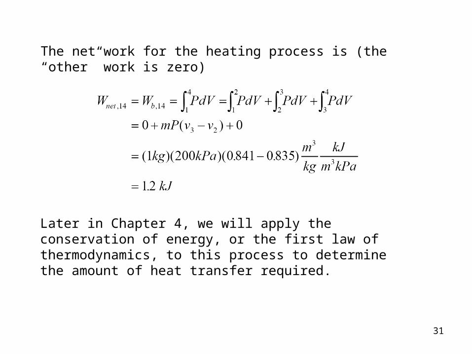
The net work for the heating process is (the “other” work is zero)
Later in Chapter 4, we will apply the conservation of energy, or the first law of thermodynamics, to this process to determine the amount of heat transfer required.

32
Example 4-5
Air undergoes a constant pressure cooling process in which the temperature decreases by 100C. What is the magnitude and direction of the work for this process?
AirWb
System Boundary
System: P
V
2 1
Property Relation: Ideal gas law, Pv = RT
Process: Constant pressure
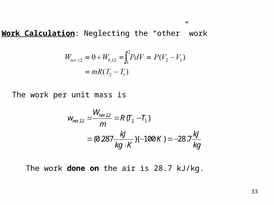
Work Calculation: Neglecting the “other” work
33
Work Calculation: Neglecting the “other” work
The work per unit mass is
,12,12 2 1( )
(0.287 )( 100 ) 28.7
netnet
Ww R T T
mkJ kJ
Kkg K kg
= = −
= − =−⋅
The work done on the air is 28.7 kJ/kg.

34
Example 4-6
Find the required heat transfer to the water in Example 4-4.
Review the solution procedure of Example 4-4 and then apply the first law to the process.
Conservation of Energy:
,14 ,14 14
in out
net net
E E E
Q W U
− =Δ− =Δ
In Example 4-4 we found that
W kJnet , .14 12=

35
The heat transfer is obtained from the first law as
,14 ,14 14net netQ W U= +Δ
where ΔU U U m u u14 4 1 4 1= − = −( )
At state 1, T1 = 100C, v1 = 0.835 m3/kg and vf < v1 < vg at T1. The quality at state 1 is
1 1
11
0.835 0.0010430.499
1.6720 0.001043
f fg
f
fg
v v x v
v vx
v
= +
− −= = =
−
1 1
419.06 (0.499)(2087.0)
1460.5
f fgu u x u
kJ
kg
= +
= +
=

36
Because state 4 is a saturated vapor state and v4 = 0.841 m3/kg, interpolating in either the saturation pressure table or saturation temperature table at v4 = vg gives
ukJ
kg4 253148= .
So
14 4 1( )
(1 )(2531.48 1460.5)
1071.0
U m u u
kJkg
kg
kJ
Δ = −
= −
=
The heat transfer is
,14 ,14 14
1.2 1071.0
1072.2
net netQ W U
kJ kJ
kJ
= +Δ
= +=
Heat in the amount of 1072.42 kJ is added to the water.

37
Specific Heats and Changes in Internal Energy and Enthalpy for Ideal Gases
Before the first law of thermodynamics can be applied to systems, ways to calculate the change in internal energy of the substance enclosed by the system boundary must be determined.
For real substances like water, the property tables are used to find the internal energy change. For ideal gases the internal energy is found by knowing the specific heats.

38
Physics defines the amount of energy needed to raise the temperature of a unit of mass of a substance one degree as the specific heat at constant volume CV for a constant-volume process, and the specific heat at constant pressure CP for a constant-pressure process.
Recall that enthalpy h is the sum of the internal energy u and the pressure-volume product Pv.
h u Pv= +
In thermodynamics, the specific heats are defined as

39
The ideal gas specific heats are written in terms of ordinary differentials as
The change in internal energy and enthalpy of ideal gases can be expressed as

40
Relation between CP and CV for Ideal Gases
Using the definition of enthalpy (h = u + Pv) and writing the differential of enthalpy, the relationship between the specific heats for ideal gases is
h u Pv
dh du d RT
C dT C dT RdT
C C RP V
P V
= += +
= += +
( )
where R is the particular gas constant. The specific heat ratio k (fluids texts often use instead of k) is defined as
kC
CP
V
=
41
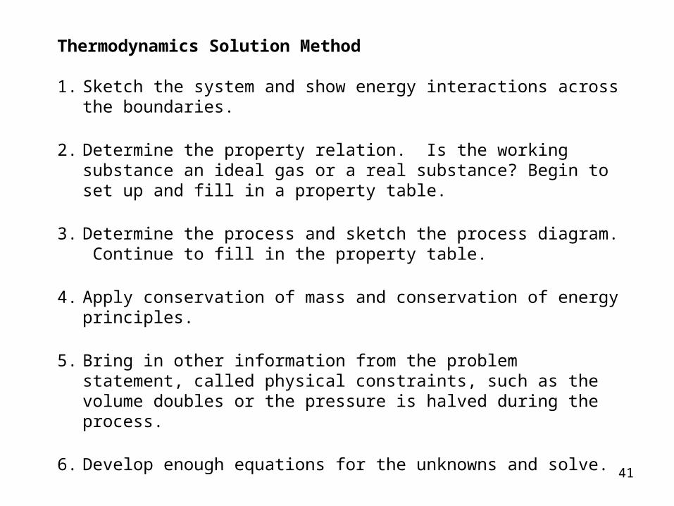
Thermodynamics Solution Method
1. Sketch the system and show energy interactions across the boundaries.
2. Determine the property relation. Is the working substance an ideal gas or a real substance? Begin to set up and fill in a property table.
3. Determine the process and sketch the process diagram. Continue to fill in the property table.
4. Apply conservation of mass and conservation of energy principles.
5. Bring in other information from the problem statement, called physical constraints, such as the volume doubles or the pressure is halved during the process.
6. Develop enough equations for the unknowns and solve.

42
Example 4-7
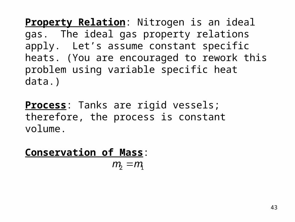
A tank contains nitrogen at 27C. The temperature rises to 127C by heat transfer to the system. Find the heat transfer and the ratio of the final pressure to the initial pressure.
System: Nitrogen in the tank.
2
T2=127C
T1=27C
P
V
1
P-V diagram for a constant volume process
Nitrogen gas
System boundary
43
Property Relation: Nitrogen is an ideal gas. The ideal gas property relations apply. Let’s assume constant specific heats. (You are encouraged to rework this problem using variable specific heat data.)
Process: Tanks are rigid vessels; therefore, the process is constant volume.
Conservation of Mass:
m m2 1=

44
Using the combined ideal gas equation of state,
PV
T
PV
T2 2
2
1 1
1
=
Since R is the particular gas constant, and the process is constant volume,
V V
P
P
T
T
K
K
2 1
2
1
2
1
127 273
27 2731333
=
= =++
=( )( )
.

45
Conservation of Energy:
The first law closed system is
in out
net net
E E E
Q W U
− =Δ− =Δ
For nitrogen undergoing a constant volume process (dV = 0), the net work is (Wother = 0)

46
Using the ideal gas relations with Wnet = 0, the first law becomes (constant specific heats)
The heat transfer per unit mass is

47
Example 4-8
Air is expanded isothermally at 100C from 0.4 MPa to 0.1 MPa. Find the ratio of the final to the initial volume, the heat transfer, and work.
System: Air contained in a piston-cylinder device, a closed system
Process: Constant temperature
P-V diagram for T= constant
P
V
1
2
Air Wb
T = const.
System boundary

48
Property Relation: Assume air is an ideal gas and use the ideal gas property relations with constant specific heats.
PV mRT
u C T TV
== −Δ ( )2 1
Conservation of Energy:
E E E
Q W Uin out
net net
− =− =
ΔΔ
The system mass is constant but is not given and cannot be calculated; therefore, let’s find the work and heat transfer per unit mass.

49
Work Calculation:
Conservation of Mass: For an ideal gas in a closed system (mass = constant), we have
m m
PV
RT
PV
RT
1 2
1 1
1
2 2
2
=
=
Since the R's cancel and T2 = T1
V
V
P
P
MPa
MPa2
1
1
2
0 4
014= = =
..

50
Then the work expression per unit mass becomes
The net work per unit mass is
w wkJ
kgnet b, , .12 120 148 4= + =

51
Now to continue with the conservation of energy to find the heat transfer. Since T2 = T1 = constant,
Δ ΔU m u mC T TV12 12 2 1 0= = − =( )
So the heat transfer per unit mass is
mq w u
q w
kJ
kg
netnet
net net
net net
=
− = ==
=
Δ 0
148 4.
The heat transferred to the air during an isothermal expansion process equals the work done.