Embed Size (px)
Citation preview

Thermo Power Plant Plomin 2 nature :: energy :: končar

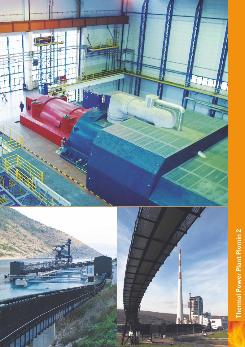
The thermal Power Plant Plomin, Unit 2 (TPP2), with 210 MW output, is located on the eastern coast of the Peninsula of Istria at the very end of Plomin Bay.The main buildings, the boiler room and the powerhouse, are built next to Unit 1. All the other facilities with the exception of the sea cooling water pumping station, the quay and the ashes depot are placed within the fenced area of the Plant. The quay and the sea cooling water pumping station are located in Plomin Bay, while the ashes depot is about 1 km away from the Plant.TEP 2 is jointly owned by the Croatian Electricity Utility (HEP) and Rheinisch-Westfällisches Elektrizitätswerk Aktiengesellschaft (RWE Energie) - Germany.
FUEL
Hard coal is used as a fuel with a lower heating value from 24 to 29.3 MJ/kg and sulphur contents between 0.3 and 1.4%.
MAIN PARTS OF THE PLANT
The main plant equipment consists of a single-tube once-through steam generator, a condensing steam turbine and a turbo generator with electrical equipment. In addition, there is a range of auxiliary systems and equipment necessary for operating the whole process of power generation. Some of them serve both Units, such as the coal supply system, the waste water treatment plant, the transport system, the slag and ashes depot, the chimney, the sea cooling water system and the raw water supply system.
THERMAL POWER PLANT PLOMIN 2
ISTRIACROATIA

Ther
mal
Pow
er P
lant
Plo
min
2


BASIC TECHNOLOGY PROCESS
Ther
mal
Pow
er P
lant
Plo
min
2

BOILER
The boiler consists of a steam generator and various auxiliary systems built into the boiler or around it, participating in the process of steam production. The manufacturer of the steam generator is the company “Đuro Đaković” from the town of Slavonski Brod, Croatia, under Sulzer company licence. Pulverized coal is used as the main fuel. The coal is transported from the depot by belt conveyors to six coal bunkers placed between the power house and the boiler. From the coal bunkers coal is continuously transported to mills where it is ground and dried. The pulverized coal dust is introduced into the boiler furnace through the fuel nozzles by a current of air. Extra light fuel oil is used for the starting and supplementary firing of the coal fuelling. The specific criteria for reduction of nitrogen oxides (NOx) have been applied to the construction of the furnace, thereby keeping the emission values of NOx significantly below the prescribed limits. Hot flue gases stream towards the top of the boiler and deliver heat to the evaporating system, the steam superheater system, the economizer and the air preheater. The further process comprises cleansing the flue gases of incombustible ingredients and ashes in the electrostatic precipitator and decrease the sulphur dioxide content in the flue gas desulphurization equipment. The process ends with the release of flue gases into the atmosphere through a chimney 340 metres high.The pressurized water-steam system consists of the evaporating system with a water-steam separator, the economizer, the steam superheater and the reheater. In respect of the circulation principle, the steam generator is once-through, type Sulzer. The main feature of this circulation principle is that all feedwater that flows freely through the feeding head evaporates during one flow in the spiral evaporator. Feedwater is supplied by three feeding pumps driven by squirrel cage induction motors, 4100 kW (two of them are necessary for the rated power, while the third one is a stand-by). Raw water, supplied from the local spring “Bubic jama”, is processed in the chemical water treatment plant into demi-water. The capacity of demi-water production for TPP 2 is 2x 25 t/h and for TPP1 2x 20 t/h.
The main technical data of the boiler:live steam generation 670 t/hlive steam pressure 14.8 Mpalive steam temperature 535°Ccoal consumption Hd = 24 MJ/kg 80 t/hsteam generator efficiency 92.9%
STEAM TURBINE
The steam turbine is of the condensing type with two casings, produced by the Steam Turbine Factory ABB from the town of Karlovac, Croatia.One casing comprises high and medium pressure. The low pressure casing is of the double-flow inlet type with direct steam exhaust into the condenser. The steam turbine comprises seven levels of unregulated extraction used for heating the boiler feedwater and the air heater.Fresh steam enters the steam turbine through stop and control valves and expands through a group of high pressure stages. From the high pressure section of the steam turbine, steam comes into the reheater. After additional heating, steam flows through appropriate stop and control valves and comes into the medium pressure section of the steam turbine where it expands through a group of medium pressure stages. After release from the medium pressure part, steam flows into the low pressure double circulating casing. The exhaust steam is condensed in the surface condenser, while the condensate is sent back to the thermal cycle by condensate pumps.The condenser is cooled by sea water. The sea cooling-water pumping station is placed in Plomin Bay, some 2.5 km away from the Plant. Pumps take water from a depth of 25 m and pump it into an open concrete water duct where the water flows by gravity to the filter station situated by the Plant. Water flows through closed piping from the filter station to the Plant.
The main technical data:gross steam turbine power (measured on the generator terminals)
210 MW
unit auxiliaries 18.8 MWnet thermal efficiency of the unit >37%condenser pressure 4.6 kPasea cooling-water flow 8.4 m3/s
COAL SUPPLY SYSTEM
The coal is brought by a ship of the Panamax type with a capacity of 60,000 tons into Plomin Bay where the quay 210 m long is placed.Unloading is performed by a closed ship-worm-type unloader that moves on rails along the quay. From the vessel unloader coal comes to the rubber quay conveyor that transports it to the weighing machine and the magnetic separator. From there to the coal depot, coal is transported by the so-called “tube” conveyor.Storing on the depot and taking of coal for further transport to the boiler bunkers is performed by a combined loader/unloader that moves on rails along the depot.
Ther
mal
Pow
er P
lant
Plo
min
2
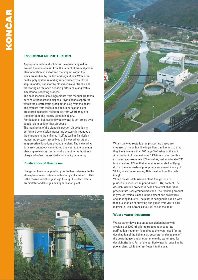
ENVIRONMENT PROTECTION
Appropriate technical solutions have been applied to protect the environment from the impact of thermal power plant operation so as to keep that impact within the limits prescribed by the law and regulations. Within the coal supply system reloading is performed by a closed ship-unloader, transport by closed conveyor tracks, and the storing on the open depot is performed along with a simultaneous wetting process.The solid incombustible ingredients from the fuel are taken care of without ground disposal. Flying ashes separated within the electrostatic precipitator, slag from the boiler and gypsum from the flue gas desulphurization plant are stored in special receptacles from where they are transported to the nearby cement industry.Purification of flue gas and waste water is performed by a special plant built for that purposes. The monitoring of the plant’s impact on air pollution is performed by emission measuring systems introduced at the entrance to the chimney itself as well as immission measuring systems assembled at 5 measuring stations at appropriate locations around the plant. The measuring data are continuously monitored and sent to the common plant supervision system as well as to other authorities in charge of or/and interested in air quality monitoring.
Purification of flue gases
Flue gases have to be purified prior to their release into the atmosphere in accordance with ecological standards. That is the reason why flue gases go through the electrostatic precipitator and flue gas desulphurization plant.
Within the electrostatic precipitator flue gases are cleansed of incombustible ingredients and ashes so that they have no more than 100 mg/m3 of ashes at the exit. A by-product of combustion of 1900 tons of coal per day, including approximately 13% of ashes, makes a total of 245 tons of ashes. 90% of that amount is separated as flying dust in the electrostatic precipitator with an efficiency of 99.8%, while the remaining 10% is ashes from the boiler (slag).Within the desulphurization plant, flue gases are purified of excessive sulphur dioxide (SO2) content. The desulphurization process is based on a wet absorption process that uses ground limestone. The resulting product is gypsum, which is used in the cement and civil works engineering industry. The plant is designed in such a way that it is capable of purifying flue gases from 700 to 3300 mg/Nm3 SO2 (i.e. from 0.3 to 1.4% of S in the coal).
Waste water treatment
Waste water flows into an accumulation basin with a volume of 1200 m3 prior to treatment. A separate purification treatment is applied to the water used for the desalination of the boiler, slag separator and mud pits of the powerhouse, and another one to the water used for desulphurization. Part of the purified water is reused in the power plant, while the rest flows into the sea.
UNIT CONTROL SYSTEM
All manual and automatic actions in the processes of the plant are controlled and supervised from the central control room. Local control is reduced to a necessary minimum and limited exclusively to those elements that do not require any direct control action during the running of the Unit. The main unit control system is TELEPERM XP (Siemens), while for the turbine control TURBOTROL (ABB) is applied. For the control of the electrical equipment a system with a PC network and SCADA software, named PROZA R/F, made by KONČAR, is implemented.
ELECTRICAL EQUIPMENT
Electrical equipment includes:
Turbo generator and unit transformer • turbo generator with auxiliary systems • excitation system • metal enclosed generator busbars with associated equipment • 13,8/240 kV unit transformerTPP2 connection to the power grid • 220 kV switchyard • 220/110 kV network transformers • 110 kV switchyard Auxiliary and general power supply • 6.3 kV switchgear • 0.4 kV switchgear • diesel generating set and emergency power supply Electric motor drivesUninterruptible power supply systems • 24, 48 and 220 V DC switchgears • 220 V, 50 Hz stabilised voltage Control, protection and measurement system
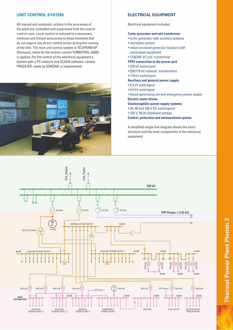
A simplified single-line diagram shows the basic structure and the main components of the electrical equipment.
Ther
mal
Pow
er P
lant
Plo
min
2
TURBO GENERATOR AND UNIT TRANSFORMER
Turbo generator with auxiliary systems
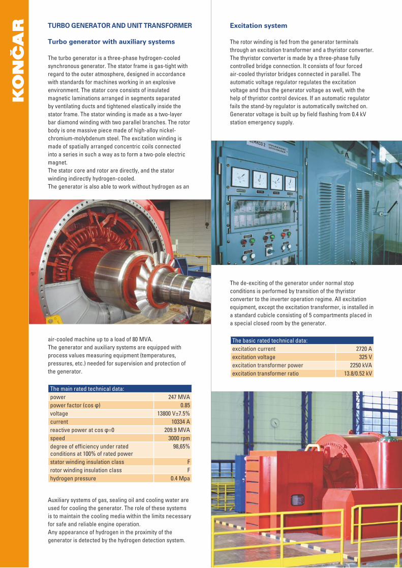
The turbo generator is a three-phase hydrogen-cooled synchronous generator. The stator frame is gas-tight with regard to the outer atmosphere, designed in accordance with standards for machines working in an explosive environment. The stator core consists of insulated magnetic laminations arranged in segments separated by ventilating ducts and tightened elastically inside the stator frame. The stator winding is made as a two-layer bar diamond winding with two parallel branches. The rotor body is one massive piece made of high-alloy nickel-chromium-molybdenum steel. The excitation winding is made of spatially arranged concentric coils connected into a series in such a way as to form a two-pole electric magnet.The stator core and rotor are directly, and the stator winding indirectly hydrogen-cooled.The generator is also able to work without hydrogen as an
air-cooled machine up to a load of 80 MVA.The generator and auxiliary systems are equipped with process values measuring equipment (temperatures, pressures, etc.) needed for supervision and protection of the generator.
The main rated technical data:power 247 MVApower factor (cos φ) 0.85voltage 13800 V±7.5%current 10334 Areactive power at cos φ=0 209.9 MVAspeed 3000 rpmdegree of efficiency under rated conditions at 100% of rated power
98,65%
stator winding insulation class Frotor winding insulation class Fhydrogen pressure 0.4 Mpa
Auxiliary systems of gas, sealing oil and cooling water are used for cooling the generator. The role of these systems is to maintain the cooling media within the limits necessary for safe and reliable engine operation.Any appearance of hydrogen in the proximity of the generator is detected by the hydrogen detection system.
Excitation system
The rotor winding is fed from the generator terminals through an excitation transformer and a thyristor converter.The thyristor converter is made by a three-phase fully controlled bridge connection. It consists of four forced air-cooled thyristor bridges connected in parallel. The automatic voltage regulator regulates the excitation voltage and thus the generator voltage as well, with the help of thyristor control devices. If an automatic regulator fails the stand-by regulator is automatically switched on. Generator voltage is built up by field flashing from 0.4 kV station emergency supply.
The de-exciting of the generator under normal stop conditions is performed by transition of the thyristor converter to the inverter operation regime. All excitation equipment, except the excitation transformer, is installed in a standard cubicle consisting of 5 compartments placed in a special closed room by the generator.
The basic rated technical data:excitation current 2720 Aexcitation voltage 325 Vexcitation transformer power 2250 kVAexcitation transformer ratio 13.8/0.52 kV

Metal enclosed generator busbars with associated equipment
The connection between the generator and the unit transformer, the neutral point and branches for connection of the equipment to generator voltage (cubicles with voltage transformers and overvoltage protection, the excitation transformer and the auxiliary supply transformer) is performed by metal enclosed busbars. The conductor and the enclosure are made of electrolytic aluminium of 99.5% purity. The diameter and the wall thickness of the main line conductors (generator – unit transformer) is440/14 mm, and the enclosure is 960/5 mm. The branches are made with the conductor of 120/4 mm and with enclosure of 640/3 mm.The enclosure of each phase closes a space under overpressure of 1.5 kPa. This overpressure is maintained by a special device preventing the entry of moisture and dust into it.Current transformers on generator terminals and the neutral point, as well as on auxiliary supply transformer branches, are placed inside the enclosure. Voltage transformers, overvoltage protection, and the resistor and the voltage transformer for earthing the neutral point, are placed in cubicles under the generator terminals.
The basic rated technical data:voltage 24 kVcurrent 12.5 kAshort circuit current 120 kA
Unit transformer
The unit transformer is placed outdoors, in front of the powerhouse. Connection to the switchyard 220 kV is made by an overhead conductor fixed by means of insulator strings between the powerhouse wall and a portal in the switchyard.Off-load voltage regulation is possible within a rangeof ±2.5%.It is equipped with a fixed fire extinguisher working with sprayed water under the pressure of CO2.
The basic technical data:rated power 245 MVAtransformer ratio 13.8/240 kVconnection group YNd5cooling OFAF
Ther
mal
Pow
er P
lant
Plo
min
2

TPP2 CONNECTION TO THE POWER GRID
220 kV Switchyard
220 kV switchyard is an outdoor air insulated switchgear (AIS). It consists of 12 bays with double busbar system and a coupling bay. The busbars are tubular, made of aluminium alloy E-Al-Mg-Si 0.5 F22 with a diameter of 120/100mm, fastened to supporting insulators.The switchyard is equipped with circuit breakers, disconnectors, instrument transformers and surge arresters, as well as line traps and capacitors for high frequency communication equipment. Three-pole SF6 circuit breakers are of the one chamber per phase type with a hydraulic operating mechanism and the possibility of one and three-pole automatic reclosing. The disconnectors are of two-column rotary type with motor drives. The current transformers are with four cores, while the capacitive voltage transformers are with two secondary windings for connection of measuring and protection devices.Measuring, protection and control devices for each bay are arranged in five relay houses located within the switchyard.Within the switchyard there is a common relay house comprising AC and DC uninterruptible power supply systems, sub-distribution for supply of 0.4 kV consumers and a switchyard stand-by control place.
The basic technical data:maximum voltage 245 kVbusbars current 2000 Afeeder current 1000 Ashort circuit current 20 kA
220/110 kV Network transformers
Connection between 220 kV and 110 kV networks is performed by means of two three-phase regulating autotransformers.A house with fixed fire extinguisher working with sprayed water under the pressure of CO2 and a relay house for measuring, protection and control equipment are placed by the side of the transformers.
The basic technical data:rated power 150 MVAtransformer ratio 220±12 x 1.25% / 115connection group YyN0OLTC ±12 x 1.25 %cooling ONAF

110 kV Switchyard
The existing switchyard has been extended by two transformer bays and one OHL bay. The concept of the existing switchyard has been retained for the extension too. The only difference is that SF6 circuit breakers instead of pneumatic ones are applied.
Ther
mal
Pow
er P
lant
Plo
min
2
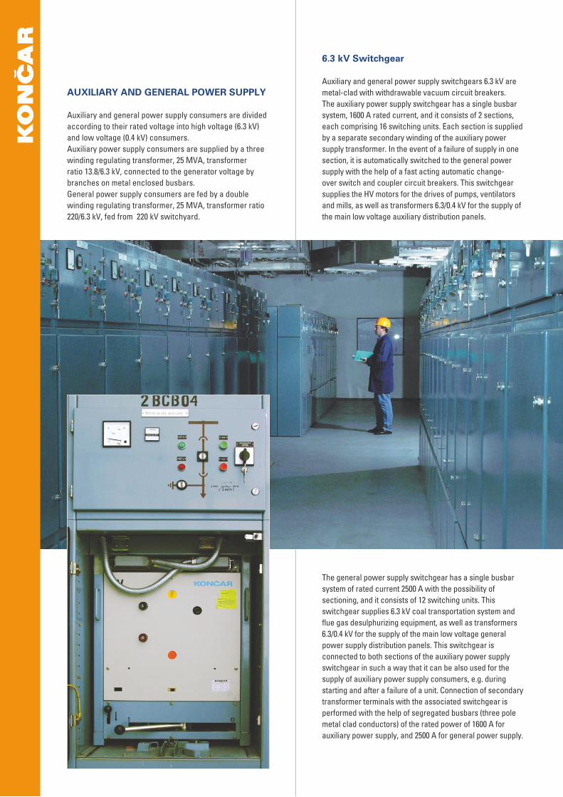
AUXILIARY AND GENERAL POWER SUPPLY
Auxiliary and general power supply consumers are divided according to their rated voltage into high voltage (6.3 kV) and low voltage (0.4 kV) consumers. Auxiliary power supply consumers are supplied by a three winding regulating transformer, 25 MVA, transformer ratio 13.8/6.3 kV, connected to the generator voltage by branches on metal enclosed busbars.General power supply consumers are fed by a double winding regulating transformer, 25 MVA, transformer ratio 220/6.3 kV, fed from 220 kV switchyard.
6.3 kV Switchgear
Auxiliary and general power supply switchgears 6.3 kV are metal-clad with withdrawable vacuum circuit breakers.The auxiliary power supply switchgear has a single busbar system, 1600 A rated current, and it consists of 2 sections, each comprising 16 switching units. Each section is supplied by a separate secondary winding of the auxiliary power supply transformer. In the event of a failure of supply in one section, it is automatically switched to the general power supply with the help of a fast acting automatic change-over switch and coupler circuit breakers. This switchgear supplies the HV motors for the drives of pumps, ventilators and mills, as well as transformers 6.3/0.4 kV for the supply of the main low voltage auxiliary distribution panels.
The general power supply switchgear has a single busbar system of rated current 2500 A with the possibility of sectioning, and it consists of 12 switching units. This switchgear supplies 6.3 kV coal transportation system and flue gas desulphurizing equipment, as well as transformers 6.3/0.4 kV for the supply of the main low voltage general power supply distribution panels. This switchgear is connected to both sections of the auxiliary power supply switchgear in such a way that it can be also used for the supply of auxiliary power supply consumers, e.g. during starting and after a failure of a unit. Connection of secondary transformer terminals with the associated switchgear is performed with the help of segregated busbars (three pole metal clad conductors) of the rated power of 1600 A for auxiliary power supply, and 2500 A for general power supply.

ELECTRIC MOTOR DRIVES
For the drives of feeding pumps, sea cooling water pumps, condensing pumps, absorber pumps, coal mills and ventilators for fresh air, flue gas, hot air for mills and recirculation of flue gas, high voltage electric motors are built in with a power range from 160 to 4100 kW, while smaller drives are equipped with low voltage motors within a wide range of powers.
Diesel generating set and emergency power supply
For the purpose of supply of essential consumers in the case of a failure of electric energy supply, a diesel generating unit 800 kVA is installed to take over the supply within a period of a few seconds.The diesel – generating set supplies the main distribution panel for emergency consumption from which power is distributed to essential consumers.Checking reliability of operation is performed by means of a testing system of the operation of the diesel generating set in parallel to the grid.
0.4 kV Switchgear
The low voltage auxiliary and general power supply switchgear consists of main distribution panels and sub-distribution panels.The main auxiliary and general supply distribution panels, as well as the main lightening supply distribution panel, placed in the space between bunkers, are supplied by corresponding 6.3kV switchgears though dry-type transformers 6.3/0.4 kV.The auxiliary power supply has two main distribution panels. Each of them is supplied from a separate transformer 1000 kVA connected to separate sections of the 6.3 kV switchgear. They supply power consumers either directly or through sub distribution panels.The main general supply distribution panel is supplied by the switchgear 6.3 kV with the help of a transformer 1000 kVA, while the main lightening supply distribution panel is supplied by the transformer 630 kVA.Auxiliary and general power supply distribution panels, in the case of a main supply failure, can be automatically switched over to supply from the stand-by transformer 1000 kVA. Consumers on the coal depot and beside the electrostatic precipitator also have separate transformers and power distribution. The coal transport system and the flue gas desulhpurizing plant have their own switchgear 6.3/0.4 kV for supply of high voltage and low voltage consumers.Sub-distribution panels are used for supply of consumers grouped by certain technological equipment. They are supplied by the main distribution panels.The 220 kV switchyard has its own sub-distribution cubicles connected to the general and the emergency power supply placed in a common relay house within the switchyard.Distribution and sub-distribution panels are made as switching units with fixed and withdrawable apparatus groups, depending on their purpose.
Ther
mal
Pow
er P
lant
Plo
min
2
CONTROL, PROTECTION AND MEASURING SYSTEM
Control of the electrical equipment is organised in several hierarchical levels:• local manual control• HV switchyard control from stand-by control place• centralised control from main control place• remote control from RCC Pehlin
The lowest control level is local manual control performed by classic control-signalling elements on the corresponding control cubicles or boards. Control cubicles of switchyard bays, as well as measuring and protection equipment, are placed in relay houses for each bay. The electrical protection is implemented by static relays, and measurement with electronic measuring converters of a high class of accuracy.For the needs of remote measuring in the HV switchyard, separate high accuracy class measuring transducers are built in as well as two-direction two-tariff active and reactive energy meters.Relay protection of the generator, unit transformers and auxiliary and general supply transformers as well as relay protection of HV electric motors is built into the separate cubicles within the relay area behind the unit control room.The stand-by control place is located in the common relay house together with the switchyard communication equipment.From the main control place in the control room, the centralised control and monitoring of all electrical equipment in TPP Plomin 2 is performed. This system is separate and independent of the control system of the technological part of the unit (boiler, turbine etc.)The scope and the method of control of the switchyard from the main and the stand-by control places is identical because it is performed by a PC network with the same SCADA software of the type PROZA R/F, produced by KONČAR KET. The network is of the type Ethernet, with a speed of 100MBs, realized with optical cables.The control of electric power equipment in the flue gas desulphurizing system as well as in the waste water treatment plant and coal transport and supply systems is performed from the main control place, and with the same PC system.The main and the stand-by control places are equipped with industrial computers and connected with controlled plants by a range of remote terminal units.The communication protocol in accordance with theIEC 60870-5-101 and optical cables are implemented for this connection.
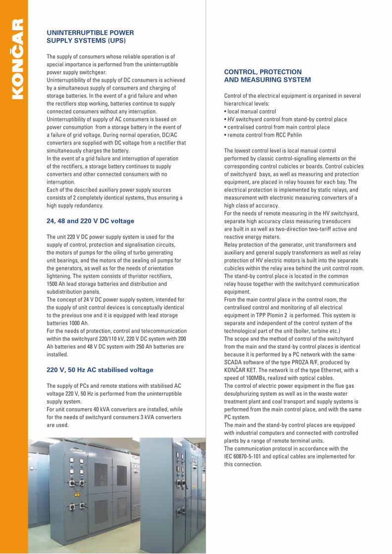
UNINTERRUPTIBLE POWER SUPPLY SYSTEMS (UPS)
The supply of consumers whose reliable operation is of special importance is performed from the uninterruptible power supply switchgear.Uninterruptibility of the supply of DC consumers is achieved by a simultaneous supply of consumers and charging of storage batteries. In the event of a grid failure and when the rectifiers stop working, batteries continue to supply connected consumers without any interruption.Uninterruptibility of supply of AC consumers is based on power consumption from a storage battery in the event of a failure of grid voltage. During normal operation, DC/AC converters are supplied with DC voltage from a rectifier that simultaneously charges the battery.In the event of a grid failure and interruption of operation of the rectifiers, a storage battery continues to supply converters and other connected consumers with no interruption.Each of the described auxiliary power supply sources consists of 2 completely identical systems, thus ensuring a high supply redundancy.
24, 48 and 220 V DC voltage
The unit 220 V DC power supply system is used for the supply of control, protection and signalisation circuits, the motors of pumps for the oiling of turbo generating unit bearings, and the motors of the sealing oil pumps for the generators, as well as for the needs of orientation lightening. The system consists of thyristor rectifiers, 1500 Ah lead storage batteries and distribution and subdistribution panels.The concept of 24 V DC power supply system, intended for the supply of unit control devices is conceptually identical to the previous one and it is equipped with lead storage batteries 1000 Ah.For the needs of protection, control and telecommunication within the switchyard 220/110 kV, 220 V DC system with 200 Ah batteries and 48 V DC system with 250 Ah batteries are installed.
220 V, 50 Hz AC stabilised voltage The supply of PCs and remote stations with stabilised AC voltage 220 V, 50 Hz is performed from the uninterruptible supply system.For unit consumers 40 kVA converters are installed, while for the needs of switchyard consumers 3 kVA converters are used.
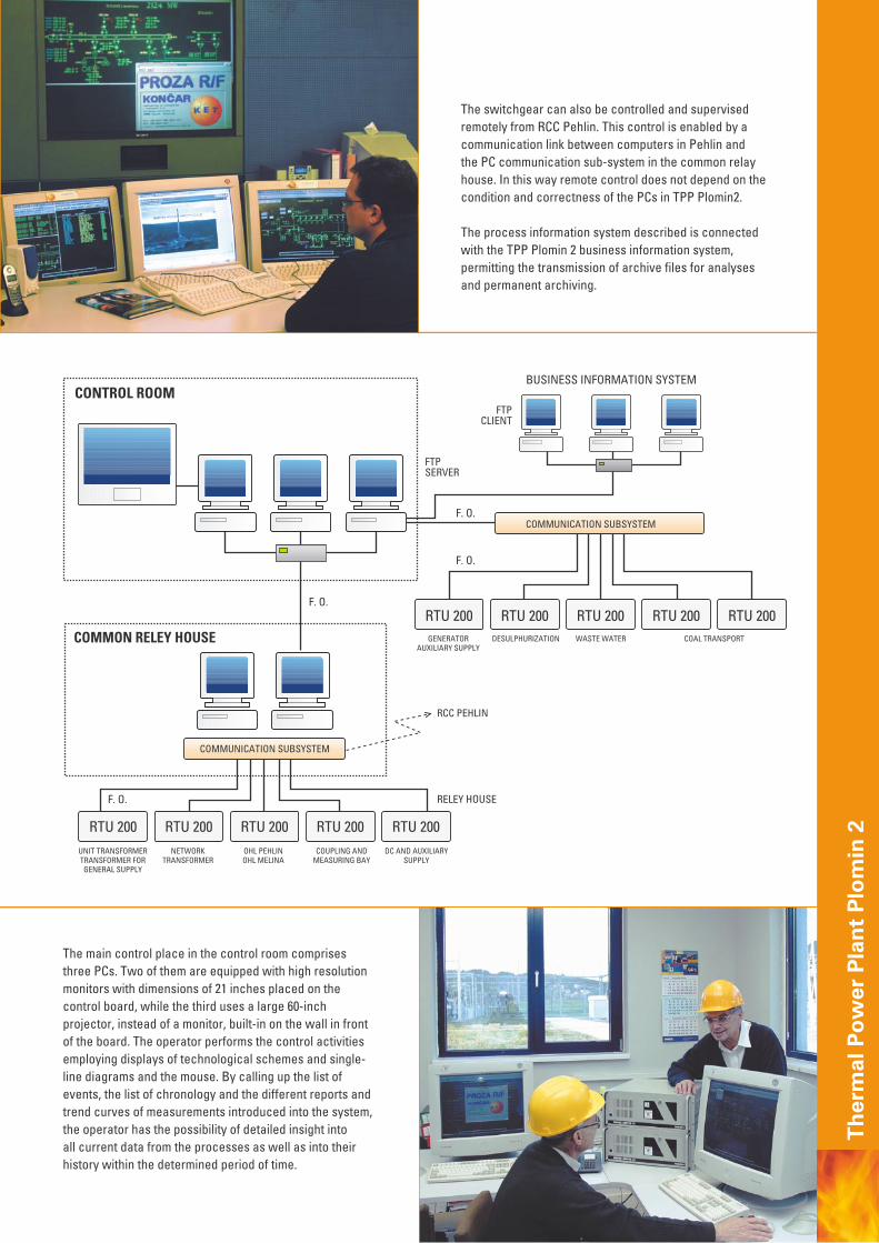
The main control place in the control room comprises three PCs. Two of them are equipped with high resolution monitors with dimensions of 21 inches placed on the control board, while the third uses a large 60-inch projector, instead of a monitor, built-in on the wall in front of the board. The operator performs the control activities employing displays of technological schemes and single-line diagrams and the mouse. By calling up the list of events, the list of chronology and the different reports and trend curves of measurements introduced into the system, the operator has the possibility of detailed insight into all current data from the processes as well as into their history within the determined period of time.
The switchgear can also be controlled and supervised remotely from RCC Pehlin. This control is enabled by a communication link between computers in Pehlin and the PC communication sub-system in the common relay house. In this way remote control does not depend on the condition and correctness of the PCs in TPP Plomin2.
The process information system described is connected with the TPP Plomin 2 business information system, permitting the transmission of archive files for analyses and permanent archiving.
Ther
mal
Pow
er P
lant
Plo
min
2

KONČAR IN THERMAL POWER PLANT PLOMIN 2
Končar participated in the construction of TPP 2 from the design stage to testing and commissioning throughout the warranty period of the plant.All activities connected with the electrical equipment were completed by KONČAR POWER PLANT AND ELECTRIC TRACTION ENGINEERING (KET) on a «turn-key» basis in the year 2002.
The following main built-in equipment is manufactured by factories belonging to the Končar Group:• Generator• Power, distribution and special transformers• Instrument transformers,• Metal enclosed generator busbars• High, medium and low voltage switchgear• All voltage levels switching apparatuses• High and low voltage electric motors • Rectifiers• Instrument and protection devices• Control software etc
Besides the above-mentioned, KET performed together with subcontractors the erection, testing and commissioning of the following plants and systems:inside and outside lighting, communication systems (interphones, internal telephone lines, radio lines), fire alarm and fire protection systems, earthing and lightning systems and anticorrosion protection.
Upon completion of the power plant, its owner, user and investor Croatian Electricity Utility (HEP) & Rheinisch-Westfällisches Elektrizitätswerk Aktiengesellschaft (RWE Energie) entrusted to KONČAR POWER PLANT AND ELECTRIC TRACTION ENGINEERING (KET), based on annual maintenance contracts, the preventive and corrective maintenance of electrical equipment and facilities that KET has supplied and installed in TEP 2.

Country Power plantNumber and power of generators
Cooling medium
Contract time
Number Power (MVA)
INDIA KAMPUR 1 40 AIR 1965
GERMANY NIEDERRAD 1 80 AIR 1973
S&CG NOVI SAD 1 194 H2 1981
B&H GACKO 1 353 H2/H2O 1981
B&H UGLJEVIK 1 353 H2/H2O 1983
S&CG ZRENJANIN 1 150 H2 1986
S&CG DRMNO 2 410 H2/H2O 1989
CROATIA ZAGREB 2 1 80 AIR 2001
CROATIA PLOMIN 2 1 247 H2 2002
SOME OF THE MOST SIGNIFICANT REFERENCES (THERMAL POWER PLANT)
Ther
mal
Pow
er P
lant
Plo
min
2

KONČAR - POWER PLANT AND ELECTRIC TRACTION ENGINEERING Inc.Fallerovo šetalište 2210000 ZagrebCroatia
tel +385 1 3667 512, 3667 513fax +385 1 3667 515e-mail: [email protected]
Publisher: Končar - Power Plant and Electric Traction Engineering Inc.
Design and prepress: (re)design, Zagreb
Photo: Končar documentation
Press: Stega Tisak, Zagreb, May, 2006.
8300-95-04-0002, rev.2