Embed Size (px)
Citation preview
Thermo™-Expansion Valves Series TX7 Technical Bulletin
www.climate.emerson.com/en-gb
TX7 series of Thermo™-Expansion Valves are designed predominantly for AC, heat pumps, close control and industrial process cooling applications. The TX7 is ideal for those applications requiring hermetic / compact size combined with stable and accurate control over wide load and evaporating temperature ranges.
Features • Monoblock, hermetic valve with brazing connections • 7 sizes up to 180 kW (R410A) • Maximum working pressure: 46 bar • Factory test pressure: 50.6 bar • Bi-Flow application
- Balanced port in normal and reverse flow directions eliminates disturbance forces resulting from condensing pressure
- Optimum static superheat in normal and reverse flow - Capacities performance in normal and reverse flow
correlates to capacity of heat pumps in cooling and heating mode
• Power Element with 65 mm diameter enables low partial load (20-25%) performance at stable superheat
• Applicable in systems with digital scroll, step less screw compressors and variable speed compressors
• Floating superheat in reverse flow (heating mode) supports evaporator efficiency during low ambient operating conditions in air cooled reversible chillers
• Laser welded stainless steel power element with a special diaphragm profile provides life expectancy against high pressure during reversed flow via external equalizer.
• Single diaphragm with negligible hysteresis withstands against higher pressure
• Fine tuning by external superheat adjusting mechanism • Special factory setting upon request. Minimum order quantity
60 pieces
TX7-Z13
R410a / R32 Selection table Capacity, R410A
(kW) Capacity, R32
(kW) Connection
Normal flow Reverse flow Normal flow Reverse flow Type Part No. Inlet x Outlet Equalizer 32.1 31.7 47.7 46.9 TX7-Z13 m 806811 12 mm x 16 mm 6 mm 32.1 31.7 47.7 46.9 TX7-Z13 806810 1/2" x 5/8" 1/4" 39.9 39.1 59.3 57.8 TX7-Z14 m 806813 16 mm x 22 mm 6 mm 39.9 39.1 59.3 57.8 TX7-Z14 806812 5/8" x 7/8" 1/4" 48.9 47.4 72.7 70.1 TX7-Z15 m 806815 16 mm x 22 mm 6 mm 48.9 47.4 72.7 70.1 TX7-Z15 806814 5/8" x 7/8" 1/4" 80.7 67.7 120 100.2 TX7-Z16 m 806817 22 mm x 28 mm 6 mm 80.7 67.7 120 100.2 TX7-Z16 806816 7/8" x 1-1/8" 1/4" 99.4 81.5 147.9 120.5 TX7-Z17 m 806819 22 mm x 28 mm 6 mm 99.4 81.5 147.9 120.5 TX7-Z17 806818 7/8" x 1-1/8" 1/4"
130.9 113.9 194.7 168.4 TX7-Z18 m 806821 22 mm x 28 mm 6 mm 130.9 113.9 194.7 168.4 TX7-Z18 806820 7/8" x 1-1/8" 1/4" 183.4 165.1 272.9 244.1 TX7-Z19 m 806823 22 mm x 28 mm 6 mm 183.4 165.1 272.9 244.1 TX7-Z19 806822 7/8" x 1-1/8" 1/4"
Note: The nominal capacities are based +4°C evaporating temperature, +38°C condensing temperature and 1 K subcooling. For other operating conditions use the quick selection in this document or the “Controls Navigator” selection tool.
Thermo™-Expansion Valves Series TX7
2 TX7_TB_EN_1907_R05.docx
R134a Selection table
Capacity, R134a (kW) With MOP Without MOP Connection Normal flow Reverse flow Type Part No. Type Part No. Inlet x Outlet Equalizer
18.1 17.9 TX7-M13 m 806839 TX7-M03 m 806825 12 mm x 16 mm 6 mm 18.1 17.9 TX7-M13 806838 TX7-M03 806824 1/2" x 5/8" 1/4" 22.5 22 TX7-M14 m 806841 TX7-M04 m 806827 16 mm x 22 mm 6 mm 22.5 22 TX7-M14 806840 TX7-M04 806826 5/8" x 7/8" 1/4" 27.5 26.7 TX7-M15 m 806843 TX7-M05 m 806829 16 mm x 22 mm 6 mm 27.5 26.7 TX7-M15 806842 TX7-M05 806828 5/8" x 7/8" 1/4" 45.4 38.2 TX7-M16 m 806845 TX7-M06 m 806831 22 mm x 28 mm 6 mm 45.4 38.2 TX7-M16 806844 TX7-M06 806830 7/8" x 1-1/8" 1/4" 56.0 45.9 TX7-M17 m 806847 TX7-M07 m 806833 22 mm x 28 mm 6 mm 56.0 45.9 TX7-M17 806846 TX7-M07 806832 7/8" x 1-1/8" 1/4" 73.7 64.1 TX7-M18 m 806849 TX7-M08 m 806835 22 mm x 28 mm 6 mm 73.7 64.1 TX7-M18 806848 TX7-M08 806834 7/8" x 1-1/8" 1/4"
103.3 93 TX7-M19 m 806851 TX7-M09 m 806837 22 mm x 28 mm 6 mm 103.3 93 TX7-M19 806850 TX7-M09 806836 7/8" x 1-1/8" 1/4"
Note: The nominal capacities are based +4°C evaporating temperature, +38°C condensing temperature and 1 K subcooling. For other operating conditions use the quick selection in this document or the “Controls Navigator” selection tool.
R407C Selection table
Capacity, R407C, (kW) With MOP Without MOP Connection Normal flow Reverse flow Type Part No. Type Part No. Inlet x Outlet Equalizer
28.9 28.6 TX7-N13 m 806868 TX7-N03 m 806853 12 mm x 16 mm 6 mm 28.9 28.6 TX7-N13 806867 TX7-N03 806852 1/2" x 5/8" 1/4" 36.0 35.2 TX7-N14 m 806870 TX7-N04 m 806855 16 mm x 22 mm 6 mm 36.0 35.2 TX7-N14 806869 TX7-N04 806854 5/8" x 7/8" 1/4" 44.1 42.7 TX7-N15 m 806872 TX7-N05 m 806857 16 mm x 22 mm 6 mm 44.1 42.7 TX7-N15 806871 TX7-N05 806856 5/8" x 7/8" 1/4" 72.7 61.1 TX7-N16 m 806874 TX7-N06 m 806859 22 mm x 28 mm 6 mm 72.7 61.1 TX7-N16 806873 TX7-N06 806858 7/8" x 1-1/8" 1/4" 89.7 73.5 TX7-N17 m 806876 TX7-N07 m 806861 22 mm x 28 mm 6 mm 89.7 73.5 TX7-N17 806875 TX7-N07 806860 7/8" x 1-1/8" 1/4"
118.1 102.7 TX7-N18 m 806878 TX7-N08 m 806863 22 mm x 28 mm 6 mm 118.1 102.7 TX7-N18 806877 TX7-N08 806862 7/8" x 1-1/8" 1/4" 165.4 148.9 TX7-N19 m 806880 TX7-N09 m 806865 22 mm x 28 mm 6 mm 165.4 148.9 TX7-N19 806879 TX7-N09 806864 7/8" x 1-1/8" 1/4"
Note: The nominal capacities are based +4°C dew point evaporating temperature, +38°C bubble point (+43°C dew point) condensing temperature and 1 K subcooling. For other operating conditions use the quick selection in this document or the “Controls Navigator” selection tool.
Thermo™-Expansion Valves Series TX7
3 TX7_TB_EN_1907_R05.docx
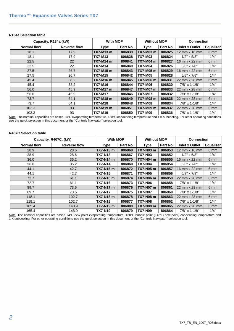
True Bi-flow Design The valve pin is balanced against inlet pressure changes in both flow directions. The inlet pressure impact negatively performance of Thermo™- Expansion valves.
Typical applications in Reversible chillers and heat pumps
Single Bi-Flow (package unit)
Note: : Flow direction in cooling mode : Flow direction in heating mode : Flow direction independent from heating and cooling mode
Two valves (package or split unit)
Single valve (package unit)
Thermo™-Expansion Valves Series TX7
4 TX7_TB_EN_1907_R05.docx
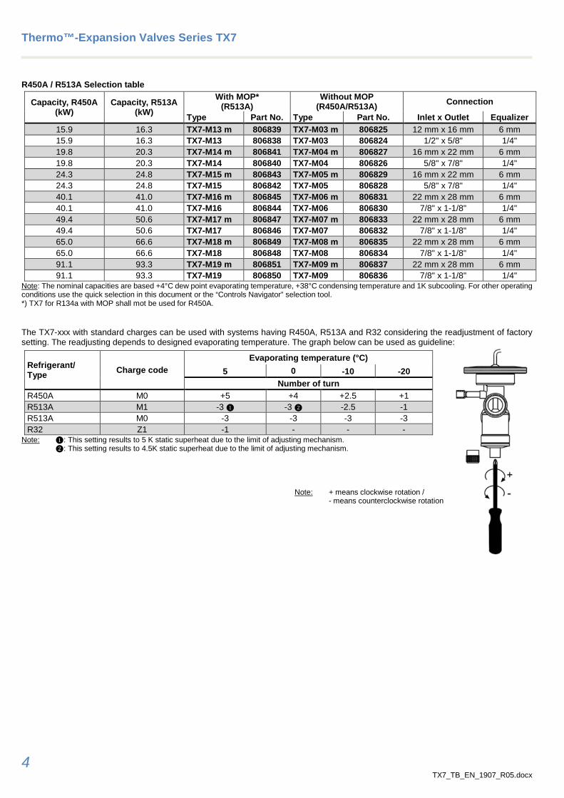
R450A / R513A Selection table
Capacity, R450A (kW)
Capacity, R513A (kW)
With MOP* (R513A)
Without MOP (R450A/R513A) Connection
Type Part No. Type Part No. Inlet x Outlet Equalizer 15.9 16.3 TX7-M13 m 806839 TX7-M03 m 806825 12 mm x 16 mm 6 mm 15.9 16.3 TX7-M13 806838 TX7-M03 806824 1/2" x 5/8" 1/4" 19.8 20.3 TX7-M14 m 806841 TX7-M04 m 806827 16 mm x 22 mm 6 mm 19.8 20.3 TX7-M14 806840 TX7-M04 806826 5/8" x 7/8" 1/4" 24.3 24.8 TX7-M15 m 806843 TX7-M05 m 806829 16 mm x 22 mm 6 mm 24.3 24.8 TX7-M15 806842 TX7-M05 806828 5/8" x 7/8" 1/4" 40.1 41.0 TX7-M16 m 806845 TX7-M06 m 806831 22 mm x 28 mm 6 mm 40.1 41.0 TX7-M16 806844 TX7-M06 806830 7/8" x 1-1/8" 1/4" 49.4 50.6 TX7-M17 m 806847 TX7-M07 m 806833 22 mm x 28 mm 6 mm 49.4 50.6 TX7-M17 806846 TX7-M07 806832 7/8" x 1-1/8" 1/4" 65.0 66.6 TX7-M18 m 806849 TX7-M08 m 806835 22 mm x 28 mm 6 mm 65.0 66.6 TX7-M18 806848 TX7-M08 806834 7/8" x 1-1/8" 1/4" 91.1 93.3 TX7-M19 m 806851 TX7-M09 m 806837 22 mm x 28 mm 6 mm 91.1 93.3 TX7-M19 806850 TX7-M09 806836 7/8" x 1-1/8" 1/4"
Note: The nominal capacities are based +4°C dew point evaporating temperature, +38°C condensing temperature and 1K subcooling. For other operating conditions use the quick selection in this document or the “Controls Navigator” selection tool. *) TX7 for R134a with MOP shall mot be used for R450A. The TX7-xxx with standard charges can be used with systems having R450A, R513A and R32 considering the readjustment of factory setting. The readjusting depends to designed evaporating temperature. The graph below can be used as guideline:
Refrigerant/ Type Charge code
Evaporating temperature (°C) 5 0 -10 -20
Number of turn R450A M0 +5 +4 +2.5 +1 R513A M1 -3 ❶ -3 ❷ -2.5 -1 R513A M0 -3 -3 -3 -3 R32 Z1 -1 - - -
Note: ❶: This setting results to 5 K static superheat due to the limit of adjusting mechanism. ❷: This setting results to 4.5K static superheat due to the limit of adjusting mechanism.
Note: + means clockwise rotation /
- means counterclockwise rotation
Thermo™-Expansion Valves Series TX7
5 TX7_TB_EN_1907_R05.docx
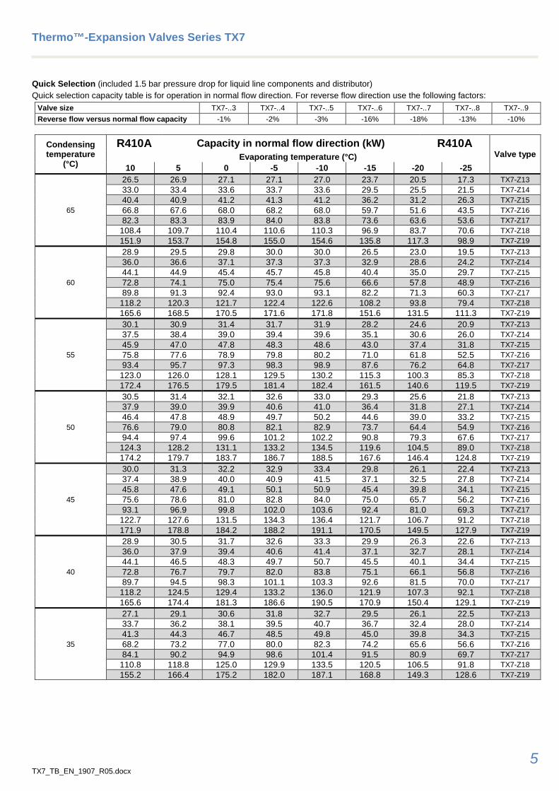
Quick Selection (included 1.5 bar pressure drop for liquid line components and distributor) Quick selection capacity table is for operation in normal flow direction. For reverse flow direction use the following factors:
Valve size TX7-..3 TX7-..4 TX7-..5 TX7-..6 TX7-..7 TX7-..8 TX7-..9 Reverse flow versus normal flow capacity -1% -2% -3% -16% -18% -13% -10%
Condensing temperature
(°C)
R410A Capacity in normal flow direction (kW) R410A Valve type Evaporating temperature (°C)
10 5 0 -5 -10 -15 -20 -25
65
26.5 26.9 27.1 27.1 27.0 23.7 20.5 17.3 TX7-Z13 33.0 33.4 33.6 33.7 33.6 29.5 25.5 21.5 TX7-Z14 40.4 40.9 41.2 41.3 41.2 36.2 31.2 26.3 TX7-Z15 66.8 67.6 68.0 68.2 68.0 59.7 51.6 43.5 TX7-Z16 82.3 83.3 83.9 84.0 83.8 73.6 63.6 53.6 TX7-Z17
108.4 109.7 110.4 110.6 110.3 96.9 83.7 70.6 TX7-Z18 151.9 153.7 154.8 155.0 154.6 135.8 117.3 98.9 TX7-Z19
60
28.9 29.5 29.8 30.0 30.0 26.5 23.0 19.5 TX7-Z13 36.0 36.6 37.1 37.3 37.3 32.9 28.6 24.2 TX7-Z14 44.1 44.9 45.4 45.7 45.8 40.4 35.0 29.7 TX7-Z15 72.8 74.1 75.0 75.4 75.6 66.6 57.8 48.9 TX7-Z16 89.8 91.3 92.4 93.0 93.1 82.2 71.3 60.3 TX7-Z17
118.2 120.3 121.7 122.4 122.6 108.2 93.8 79.4 TX7-Z18 165.6 168.5 170.5 171.6 171.8 151.6 131.5 111.3 TX7-Z19
55
30.1 30.9 31.4 31.7 31.9 28.2 24.6 20.9 TX7-Z13 37.5 38.4 39.0 39.4 39.6 35.1 30.6 26.0 TX7-Z14 45.9 47.0 47.8 48.3 48.6 43.0 37.4 31.8 TX7-Z15 75.8 77.6 78.9 79.8 80.2 71.0 61.8 52.5 TX7-Z16 93.4 95.7 97.3 98.3 98.9 87.6 76.2 64.8 TX7-Z17
123.0 126.0 128.1 129.5 130.2 115.3 100.3 85.3 TX7-Z18 172.4 176.5 179.5 181.4 182.4 161.5 140.6 119.5 TX7-Z19
50
30.5 31.4 32.1 32.6 33.0 29.3 25.6 21.8 TX7-Z13 37.9 39.0 39.9 40.6 41.0 36.4 31.8 27.1 TX7-Z14 46.4 47.8 48.9 49.7 50.2 44.6 39.0 33.2 TX7-Z15 76.6 79.0 80.8 82.1 82.9 73.7 64.4 54.9 TX7-Z16 94.4 97.4 99.6 101.2 102.2 90.8 79.3 67.6 TX7-Z17
124.3 128.2 131.1 133.2 134.5 119.6 104.5 89.0 TX7-Z18 174.2 179.7 183.7 186.7 188.5 167.6 146.4 124.8 TX7-Z19
45
30.0 31.3 32.2 32.9 33.4 29.8 26.1 22.4 TX7-Z13 37.4 38.9 40.0 40.9 41.5 37.1 32.5 27.8 TX7-Z14 45.8 47.6 49.1 50.1 50.9 45.4 39.8 34.1 TX7-Z15 75.6 78.6 81.0 82.8 84.0 75.0 65.7 56.2 TX7-Z16 93.1 96.9 99.8 102.0 103.6 92.4 81.0 69.3 TX7-Z17
122.7 127.6 131.5 134.3 136.4 121.7 106.7 91.2 TX7-Z18 171.9 178.8 184.2 188.2 191.1 170.5 149.5 127.9 TX7-Z19
40
28.9 30.5 31.7 32.6 33.3 29.9 26.3 22.6 TX7-Z13 36.0 37.9 39.4 40.6 41.4 37.1 32.7 28.1 TX7-Z14 44.1 46.5 48.3 49.7 50.7 45.5 40.1 34.4 TX7-Z15 72.8 76.7 79.7 82.0 83.8 75.1 66.1 56.8 TX7-Z16 89.7 94.5 98.3 101.1 103.3 92.6 81.5 70.0 TX7-Z17
118.2 124.5 129.4 133.2 136.0 121.9 107.3 92.1 TX7-Z18 165.6 174.4 181.3 186.6 190.5 170.9 150.4 129.1 TX7-Z19
35
27.1 29.1 30.6 31.8 32.7 29.5 26.1 22.5 TX7-Z13 33.7 36.2 38.1 39.5 40.7 36.7 32.4 28.0 TX7-Z14 41.3 44.3 46.7 48.5 49.8 45.0 39.8 34.3 TX7-Z15 68.2 73.2 77.0 80.0 82.3 74.2 65.6 56.6 TX7-Z16 84.1 90.2 94.9 98.6 101.4 91.5 80.9 69.7 TX7-Z17
110.8 118.8 125.0 129.9 133.5 120.5 106.5 91.8 TX7-Z18 155.2 166.4 175.2 182.0 187.1 168.8 149.3 128.6 TX7-Z19
Thermo™-Expansion Valves Series TX7
6 TX7_TB_EN_1907_R05.docx
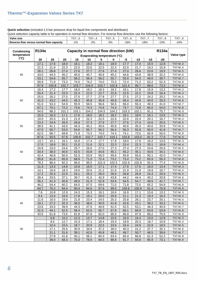
Quick selection (included 1.5 bar pressure drop for liquid line components and distributor) Quick selection capacity table is for operation in normal flow direction. For reverse flow direction use the following factors:
Valve size TX7-..3 TX7-..4 TX7-..5 TX7-..6 TX7-..7 TX7-..8 TX7-..9 Reverse flow versus normal flow capacity -1% -2% -3% -16% -18% -13% -10%
Condensing temperature
(°C)
R134a Capacity in normal flow direction (kW) R134a Valve type Evaporating temperature (°C)
30 25 20 15 10 5 0 -5 -10 -15 -20
65
17.1 17.6 18.0 18.1 18.2 18.1 18.0 17.7 17.4 15.5 12.8 TX7-M..3 21.3 21.9 22.3 22.5 22.6 22.5 22.3 22.0 21.7 19.2 15.9 TX7-M..4 26.1 26.8 27.4 27.6 27.7 27.6 27.4 27.0 26.6 23.6 19.5 TX7-M..5 43.0 44.3 45.2 45.6 45.7 45.6 45.2 44.6 43.8 38.9 32.2 TX7-M..6 53.1 54.6 55.7 56.2 56.4 56.2 55.7 55.0 54.0 48.0 39.7 TX7-M..7 69.9 71.9 73.3 74.0 74.2 74.0 73.3 72.4 71.2 63.2 52.3 TX7-M..8 97.9 100.8 102.7 103.7 104.0 103.7 102.8 101.4 99.7 88.6 73.3 TX7-M..9
60
16.4 17.2 17.7 18.0 18.2 18.3 18.2 18.1 17.8 15.9 13.2 TX7-M..3 20.4 21.4 22.0 22.4 22.6 22.7 22.6 22.5 22.2 19.8 16.4 TX7-M..4 25.0 26.2 27.0 27.5 27.7 27.8 27.7 27.5 27.2 24.2 20.2 TX7-M..5 41.3 43.2 44.5 45.3 45.8 45.9 45.8 45.4 44.9 40.0 33.3 TX7-M..6 51.0 53.3 54.9 55.9 56.5 56.6 56.5 56.0 55.3 49.3 41.0 TX7-M..7 67.1 70.1 72.2 73.6 74.3 74.6 74.3 73.7 72.8 65.0 54.0 TX7-M..8 94.0 98.3 101.2 103.1 104.2 104.5 104.2 103.3 102.1 91.1 75.7 TX7-M..9
55
15.3 16.3 17.1 17.6 18.0 18.1 18.2 18.1 18.0 16.1 13.5 TX7-M..3 19.0 20.3 21.3 21.9 22.3 22.5 22.6 22.6 22.4 20.1 16.7 TX7-M..4 23.3 24.9 26.0 26.8 27.3 27.6 27.7 27.6 27.4 24.6 20.5 TX7-M..5 38.5 41.1 43.0 44.3 45.1 45.6 45.8 45.6 45.3 40.6 33.9 TX7-M..6 47.5 50.7 53.0 54.6 55.7 56.2 56.4 56.3 55.8 50.0 41.8 TX7-M..7 62.5 66.7 69.8 71.9 73.3 74.0 74.3 74.1 73.5 65.9 55.0 TX7-M..8 87.6 93.5 97.8 100.8 102.7 103.7 104.1 103.8 103.0 92.3 77.0 TX7-M..9
50
13.7 15.1 16.1 16.9 17.4 17.7 17.9 18.0 17.9 16.2 13.5 TX7-M..3 17.0 18.8 20.1 21.0 21.6 22.1 22.3 22.4 22.3 20.1 16.8 TX7-M..4 20.8 23.0 24.6 25.7 26.5 27.0 27.3 27.4 27.3 24.6 20.6 TX7-M..5 34.4 38.0 40.6 42.5 43.8 44.6 45.1 45.2 45.1 40.6 34.1 TX7-M..6 42.4 46.8 50.0 52.3 53.9 55.0 55.6 55.8 55.6 50.1 42.0 TX7-M..7 55.8 61.6 65.9 68.9 71.0 72.4 73.2 73.4 73.2 65.9 55.3 TX7-M..8 78.2 86.4 92.3 96.6 99.5 101.5 102.5 102.9 102.6 92.4 77.4 TX7-M..9
45
11.3 13.3 14.8 15.8 16.5 17.1 17.4 17.6 17.6 16.0 13.4 TX7-M..3 14.1 16.6 18.3 19.6 20.6 21.2 21.6 21.9 21.9 19.9 16.7 TX7-M..4 17.2 20.3 22.5 24.1 25.2 26.0 26.5 26.8 26.9 24.3 20.5 TX7-M..5 28.4 33.5 37.1 39.7 41.6 42.9 43.8 44.2 44.4 40.2 33.8 TX7-M..6 35.1 41.3 45.8 49.0 51.3 52.9 53.9 54.5 54.7 49.5 41.7 TX7-M..7 46.2 54.4 60.2 64.5 67.5 69.6 71.0 71.8 72.0 65.2 54.9 TX7-M..8 64.7 76.2 84.4 90.4 94.6 97.6 99.5 100.6 100.9 91.4 76.9 TX7-M..9
40
7.6 10.8 12.9 14.3 15.3 16.1 16.6 16.9 17.1 15.6 13.2 TX7-M..3 9.4 13.4 16.0 17.8 19.1 20.0 20.6 21.1 21.3 19.4 16.4 TX7-M..4
11.6 16.5 19.6 21.8 23.4 24.5 25.3 25.8 26.1 23.7 20.1 TX7-M..5 19.1 27.2 32.3 36.0 38.6 40.5 41.8 42.6 43.1 39.2 33.2 TX7-M..6 23.6 33.5 39.9 44.3 47.6 49.9 51.5 52.5 53.1 48.3 40.9 TX7-M..7 31.0 44.1 52.5 58.4 62.6 65.7 67.8 69.1 69.9 63.6 53.9 TX7-M..8 43.5 61.8 73.6 81.8 87.8 92.0 95.0 96.9 97.9 89.2 75.5 TX7-M..9
35
6.8 10.2 12.3 13.7 14.8 15.5 16.0 16.4 15.0 12.8 TX7-M..3 8.5 12.7 15.3 17.1 18.4 19.3 19.9 20.3 18.7 15.9 TX7-M..4 10.4 15.5 18.7 20.9 22.5 23.6 24.4 24.9 22.9 19.5 TX7-M..5 17.1 25.6 30.9 34.6 37.2 39.0 40.3 41.2 37.7 32.1 TX7-M..6 21.1 31.6 38.1 42.6 45.8 48.1 49.7 50.7 46.5 39.6 TX7-M..7 27.8 41.6 50.1 56.1 60.3 63.4 65.4 66.8 61.3 52.2 TX7-M..8 39.0 58.3 70.3 78.6 84.5 88.8 91.7 93.6 85.9 73.1 TX7-M..9
Thermo™-Expansion Valves Series TX7
7 TX7_TB_EN_1907_R05.docx
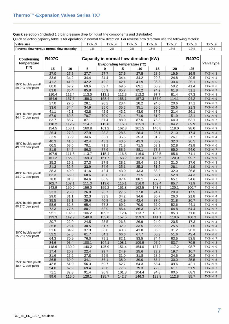
Quick selection (included 1.5 bar pressure drop for liquid line components and distributor) Quick selection capacity table is for operation in normal flow direction. For reverse flow direction use the following factors:
Valve size TX7-..3 TX7-..4 TX7-..5 TX7-..6 TX7-..7 TX7-..8 TX7-..9 Reverse flow versus normal flow capacity -1% -2% -3% -16% -18% -13% -10%
Condensing temperature
(°C)
R407C Capacity in normal flow direction (kW) R407C Valve type Evaporating temperature (°C)
15 10 5 0 -5 -10 -15 -20 -25
55°C bubble point/ 59.2°C dew point
27.0 27.5 27.7 27.7 27.6 27.5 23.9 19.9 16.5 TX7-N..3 33.6 34.2 34.4 34.4 34.4 34.2 29.8 24.8 20.5 TX7-N..4 41.2 41.9 42.2 42.2 42.1 41.9 36.5 30.4 25.1 TX7-N..5 68.0 69.2 69.6 69.7 69.5 69.1 60.2 50.2 41.4 TX7-N..6 83.8 85.4 85.8 85.9 85.7 85.2 74.2 61.8 51.1 TX7-N..7
110.4 112.4 113.0 113.1 112.8 112.2 97.7 81.4 67.3 TX7-N..8 154.6 157.5 158.3 158.4 158.1 157.3 137.0 114.1 94.2 TX7-N..9
50°C bubble point/ 54.4°C dew point
27.0 27.6 28.1 28.2 28.4 28.2 24.6 20.6 17.1 TX7-N..3 33.6 34.4 34.9 35.0 35.3 35.1 30.6 25.6 21.3 TX7-N..4 41.1 42.1 42.8 42.9 43.2 43.0 37.5 31.4 26.1 TX7-N..5 67.9 69.5 70.7 70.9 71.4 71.0 61.9 51.9 43.1 TX7-N..6 83.7 85.7 87.1 87.4 88.0 87.5 76.3 64.0 53.1 TX7-N..7
110.2 112.9 114.7 115.0 115.8 115.3 100.5 84.2 69.9 TX7-N..8 154.5 158.1 160.8 161.2 162.3 161.5 140.8 118.0 98.0 TX7-N..9
45°C bubble point/ 49.6°C dew point
26.4 27.3 27.9 28.3 28.5 28.4 25.1 21.0 17.4 TX7-N..3 32.9 33.9 34.6 35.1 35.5 35.3 31.2 26.1 21.7 TX7-N..4 40.3 41.5 42.4 43.1 43.5 43.3 38.2 32.0 26.5 TX7-N..5 66.5 68.5 70.1 71.1 71.8 71.5 63.1 52.8 43.8 TX7-N..6 81.9 84.5 86.3 87.6 88.5 88.1 77.8 65.0 54.0 TX7-N..7
107.9 111.3 113.7 115.4 116.5 116.0 102.5 85.6 71.1 TX7-N..8 151.2 155.9 159.3 161.7 163.2 162.6 143.6 120.0 99.7 TX7-N..9
40°C bubble point/ 44.9°C dew point
25.2 26.2 27.3 27.8 28.2 28.4 25.1 21.0 17.6 TX7-N..3 31.3 32.6 33.9 34.6 35.1 35.3 31.2 26.1 21.9 TX7-N..4 38.3 40.0 41.6 42.4 43.0 43.3 38.2 32.0 26.8 TX7-N..5 63.3 66.0 68.6 70.0 70.9 71.5 63.1 52.8 44.3 TX7-N..6 78.0 81.3 84.6 86.3 87.4 88.1 77.8 65.1 54.6 TX7-N..7
102.7 107.1 111.3 113.6 115.1 116.0 102.4 85.7 71.9 TX7-N..8 143.9 150.0 156.0 159.2 161.3 162.5 143.5 120.1 100.7 TX7-N..9
35°C bubble point/ 40.1°C dew point
23.3 25.0 26.0 26.7 27.5 27.8 24.7 20.9 17.5 TX7-N..3 29.0 31.1 32.3 33.3 34.2 34.6 30.7 26.0 21.8 TX7-N..4 35.5 38.1 39.6 40.8 41.9 42.4 37.6 31.8 26.7 TX7-N..5 58.6 62.8 65.4 67.3 69.2 70.0 62.0 52.6 44.1 TX7-N..6 72.3 77.5 80.7 82.9 85.4 86.3 76.5 64.8 54.4 TX7-N..7 95.1 102.0 106.2 109.2 112.4 113.7 100.7 85.3 71.6 TX7-N..8
133.3 142.9 148.8 153.0 157.5 159.3 141.1 119.6 100.3 TX7-N..9
30°C bubble point/ 35.2°C dew point
20.7 22.9 24.5 25.5 26.5 26.9 24.0 20.5 17.3 TX7-N..3 25.8 28.4 30.5 31.7 32.9 33.5 29.8 25.5 21.5 TX7-N..4 31.6 34.9 37.3 38.8 40.3 41.0 36.5 31.2 26.3 TX7-N..5 52.2 57.5 61.7 64.1 66.6 67.7 60.3 51.6 43.4 TX7-N..6 64.3 70.9 76.0 79.1 82.1 83.5 74.4 63.5 53.5 TX7-N..7 84.6 93.4 100.1 104.1 108.1 109.9 97.9 83.7 70.5 TX7-N..8
118.6 130.9 140.2 145.9 151.4 154.0 137.2 117.2 98.7 TX7-N..9
25°C bubble point/ 30.4°C dew point
17.4 20.3 22.4 23.7 24.9 25.6 23.2 19.7 16.7 TX7-N..3 21.6 25.2 27.8 29.5 31.0 31.8 28.9 24.5 20.8 TX7-N..4 26.5 30.9 34.1 36.1 38.0 39.0 35.4 30.0 25.5 TX7-N..5 43.8 51.0 56.3 59.7 62.7 64.3 58.4 49.6 42.1 TX7-N..6 54.0 62.9 69.4 73.6 77.3 79.3 72.0 61.1 51.9 TX7-N..7 71.1 82.8 91.4 96.9 101.8 104.4 94.8 80.5 68.3 TX7-N..8 99.6 116.0 128.1 135.7 142.7 146.3 132.8 112.8 95.7 TX7-N..9

Thermo™-Expansion Valves Series TX7
8 TX7_TB_EN_1907_R05.docx
Quick selection (included 1.5 bar pressure drop for liquid line components and distributor) Quick selection capacity table is for operation in normal flow direction. For reverse flow direction use the following factors:
Valve size TX7-..3 TX7-..4 TX7-..5 TX7-..6 TX7-..7 TX7-..8 TX7-..9 Reverse flow versus normal flow capacity -1% -2% -3% -16% -18% -13% -10%
Condensing temperature
(°C)
R32 Capacity in normal flow direction (kW) R32 Valve type Evaporating temperature (°C)
10 5 0 -5 -10 -15 -20 -25
65
46.1 47.1 47.9 48.5 48.9 43.4 38.0 32.5 TX7-Z13 57.3 58.5 59.5 60.2 60.8 54.0 47.2 40.3 TX7-Z14 70.2 71.7 72.9 73.8 74.5 66.2 57.9 49.4 TX7-Z15
115.9 118.4 120.4 121.9 122.9 109.2 95.5 81.6 TX7-Z16 142.9 146.0 148.4 150.2 151.5 134.7 117.8 100.6 TX7-Z17 188.1 192.2 195.4 197.8 199.5 177.3 155.1 132.5 TX7-Z18 263.6 269.3 273.8 277.2 279.5 248.5 217.3 185.7 TX7-Z19
60
47.4 48.7 49.7 50.4 51.0 45.4 39.8 34.1 TX7-Z13 59.0 60.5 61.7 62.7 63.4 56.5 49.5 42.4 TX7-Z14 72.3 74.2 75.7 76.8 77.7 69.2 60.6 51.9 TX7-Z15
119.3 122.4 124.9 126.8 128.2 114.2 100.1 85.7 TX7-Z16 147.1 150.9 153.9 156.3 158.1 140.8 123.4 105.7 TX7-Z17 193.7 198.7 202.7 205.8 208.1 185.4 162.5 139.1 TX7-Z18 271.4 278.4 284.0 288.4 291.6 259.8 227.7 195.0 TX7-Z19
55
47.6 49.1 50.3 51.3 52.0 46.4 40.8 35.0 TX7-Z13 59.2 61.1 62.6 63.7 64.6 57.7 50.7 43.5 TX7-Z14 72.6 74.8 76.7 78.1 79.2 70.8 62.2 53.3 TX7-Z15
119.8 123.5 126.6 128.9 130.8 116.8 102.6 88.0 TX7-Z16 147.7 152.3 156.0 158.9 161.2 144.0 126.5 108.5 TX7-Z17 194.4 200.5 205.4 209.3 212.3 189.6 166.5 142.9 TX7-Z18 272.4 281.0 287.8 293.3 297.4 265.7 233.4 200.2 TX7-Z19
50
46.9 48.7 50.1 51.3 52.2 46.7 41.2 35.4 TX7-Z13 58.3 60.5 62.3 63.7 64.9 58.1 51.2 44.0 TX7-Z14 71.4 74.1 76.3 78.1 79.5 71.2 62.7 53.9 TX7-Z15
117.9 122.4 126.0 128.9 131.2 117.6 103.5 89.0 TX7-Z16 145.3 150.8 155.3 158.9 161.8 144.9 127.6 109.7 TX7-Z17 191.3 198.6 204.5 209.3 213.0 190.8 168.0 144.5 TX7-Z18 268.1 278.3 286.6 293.3 298.4 267.4 235.4 202.4 TX7-Z19
45
45.3 47.4 49.1 50.5 51.7 46.4 41.0 35.3 TX7-Z13 56.3 58.9 61.1 62.8 64.2 57.7 51.0 43.9 TX7-Z14 69.0 72.2 74.9 77.0 78.7 70.7 62.5 53.8 TX7-Z15
113.9 119.2 123.6 127.1 129.9 116.8 103.1 88.9 TX7-Z16 140.4 147.0 152.3 156.7 160.1 144.0 127.1 109.6 TX7-Z17 184.8 193.5 200.6 206.3 210.9 189.6 167.4 144.3 TX7-Z18 259.0 271.1 281.1 289.1 295.5 265.6 234.6 202.2 TX7-Z19
40
42.9 45.4 47.5 49.2 50.5 45.6 40.4 34.9 TX7-Z13 53.3 56.4 59.0 61.1 62.8 56.7 50.2 43.4 TX7-Z14 65.3 69.2 72.3 74.9 76.9 69.5 61.6 53.2 TX7-Z15
107.8 114.2 119.4 123.6 127.0 114.7 101.6 87.8 TX7-Z16 132.9 140.8 147.2 152.4 156.6 141.4 125.3 108.3 TX7-Z17 174.9 185.3 193.8 200.7 206.2 186.1 165.0 142.6 TX7-Z18 245.1 259.7 271.6 281.2 288.9 260.8 231.2 199.8 TX7-Z19
35
39.6 42.6 45.1 47.2 48.8 44.3 39.4 34.2 TX7-Z13 49.2 53.0 56.1 58.6 60.6 55.0 49.0 42.5 TX7-Z14 60.3 65.0 68.8 71.9 74.3 67.4 60.0 52.1 TX7-Z15 99.5 107.3 113.5 118.6 122.7 111.3 99.1 86.0 TX7-Z16
122.7 132.2 140.0 146.2 151.2 137.3 122.2 106.0 TX7-Z17 161.5 174.1 184.3 192.5 199.1 180.7 160.9 139.5 TX7-Z18 226.4 244.0 258.2 269.8 279.1 253.2 225.4 195.5 TX7-Z19
Thermo™-Expansion Valves Series TX7
9 TX7_TB_EN_1907_R05.docx
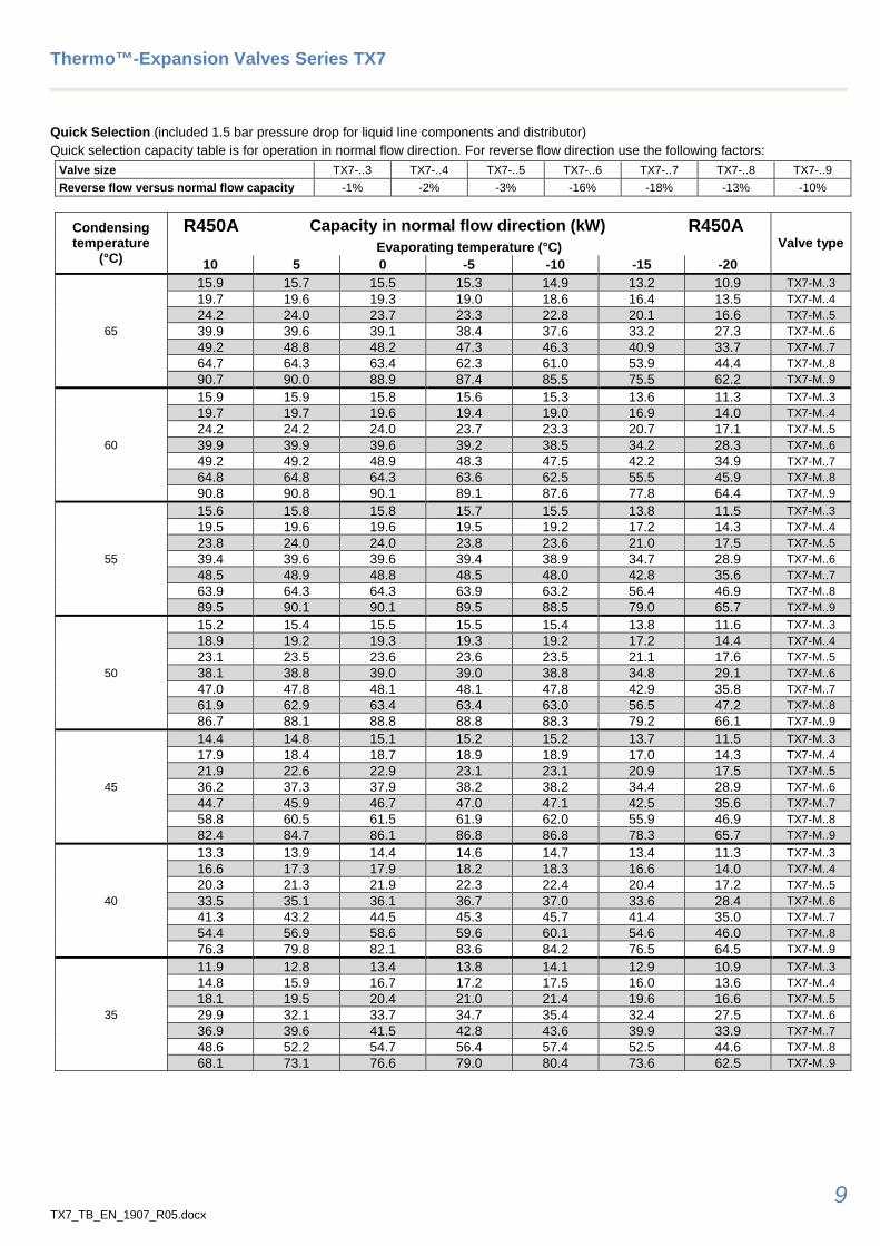
Quick Selection (included 1.5 bar pressure drop for liquid line components and distributor) Quick selection capacity table is for operation in normal flow direction. For reverse flow direction use the following factors:
Valve size TX7-..3 TX7-..4 TX7-..5 TX7-..6 TX7-..7 TX7-..8 TX7-..9 Reverse flow versus normal flow capacity -1% -2% -3% -16% -18% -13% -10%
Condensing temperature
(°C)
R450A Capacity in normal flow direction (kW) R450A Valve type Evaporating temperature (°C)
10 5 0 -5 -10 -15 -20
65
15.9 15.7 15.5 15.3 14.9 13.2 10.9 TX7-M..3 19.7 19.6 19.3 19.0 18.6 16.4 13.5 TX7-M..4 24.2 24.0 23.7 23.3 22.8 20.1 16.6 TX7-M..5 39.9 39.6 39.1 38.4 37.6 33.2 27.3 TX7-M..6 49.2 48.8 48.2 47.3 46.3 40.9 33.7 TX7-M..7 64.7 64.3 63.4 62.3 61.0 53.9 44.4 TX7-M..8 90.7 90.0 88.9 87.4 85.5 75.5 62.2 TX7-M..9
60
15.9 15.9 15.8 15.6 15.3 13.6 11.3 TX7-M..3 19.7 19.7 19.6 19.4 19.0 16.9 14.0 TX7-M..4 24.2 24.2 24.0 23.7 23.3 20.7 17.1 TX7-M..5 39.9 39.9 39.6 39.2 38.5 34.2 28.3 TX7-M..6 49.2 49.2 48.9 48.3 47.5 42.2 34.9 TX7-M..7 64.8 64.8 64.3 63.6 62.5 55.5 45.9 TX7-M..8 90.8 90.8 90.1 89.1 87.6 77.8 64.4 TX7-M..9
55
15.6 15.8 15.8 15.7 15.5 13.8 11.5 TX7-M..3 19.5 19.6 19.6 19.5 19.2 17.2 14.3 TX7-M..4 23.8 24.0 24.0 23.8 23.6 21.0 17.5 TX7-M..5 39.4 39.6 39.6 39.4 38.9 34.7 28.9 TX7-M..6 48.5 48.9 48.8 48.5 48.0 42.8 35.6 TX7-M..7 63.9 64.3 64.3 63.9 63.2 56.4 46.9 TX7-M..8 89.5 90.1 90.1 89.5 88.5 79.0 65.7 TX7-M..9
50
15.2 15.4 15.5 15.5 15.4 13.8 11.6 TX7-M..3 18.9 19.2 19.3 19.3 19.2 17.2 14.4 TX7-M..4 23.1 23.5 23.6 23.6 23.5 21.1 17.6 TX7-M..5 38.1 38.8 39.0 39.0 38.8 34.8 29.1 TX7-M..6 47.0 47.8 48.1 48.1 47.8 42.9 35.8 TX7-M..7 61.9 62.9 63.4 63.4 63.0 56.5 47.2 TX7-M..8 86.7 88.1 88.8 88.8 88.3 79.2 66.1 TX7-M..9
45
14.4 14.8 15.1 15.2 15.2 13.7 11.5 TX7-M..3 17.9 18.4 18.7 18.9 18.9 17.0 14.3 TX7-M..4 21.9 22.6 22.9 23.1 23.1 20.9 17.5 TX7-M..5 36.2 37.3 37.9 38.2 38.2 34.4 28.9 TX7-M..6 44.7 45.9 46.7 47.0 47.1 42.5 35.6 TX7-M..7 58.8 60.5 61.5 61.9 62.0 55.9 46.9 TX7-M..8 82.4 84.7 86.1 86.8 86.8 78.3 65.7 TX7-M..9
40
13.3 13.9 14.4 14.6 14.7 13.4 11.3 TX7-M..3 16.6 17.3 17.9 18.2 18.3 16.6 14.0 TX7-M..4 20.3 21.3 21.9 22.3 22.4 20.4 17.2 TX7-M..5 33.5 35.1 36.1 36.7 37.0 33.6 28.4 TX7-M..6 41.3 43.2 44.5 45.3 45.7 41.4 35.0 TX7-M..7 54.4 56.9 58.6 59.6 60.1 54.6 46.0 TX7-M..8 76.3 79.8 82.1 83.6 84.2 76.5 64.5 TX7-M..9
35
11.9 12.8 13.4 13.8 14.1 12.9 10.9 TX7-M..3 14.8 15.9 16.7 17.2 17.5 16.0 13.6 TX7-M..4 18.1 19.5 20.4 21.0 21.4 19.6 16.6 TX7-M..5 29.9 32.1 33.7 34.7 35.4 32.4 27.5 TX7-M..6 36.9 39.6 41.5 42.8 43.6 39.9 33.9 TX7-M..7 48.6 52.2 54.7 56.4 57.4 52.5 44.6 TX7-M..8 68.1 73.1 76.6 79.0 80.4 73.6 62.5 TX7-M..9
Thermo™-Expansion Valves Series TX7
10 TX7_TB_EN_1907_R05.docx
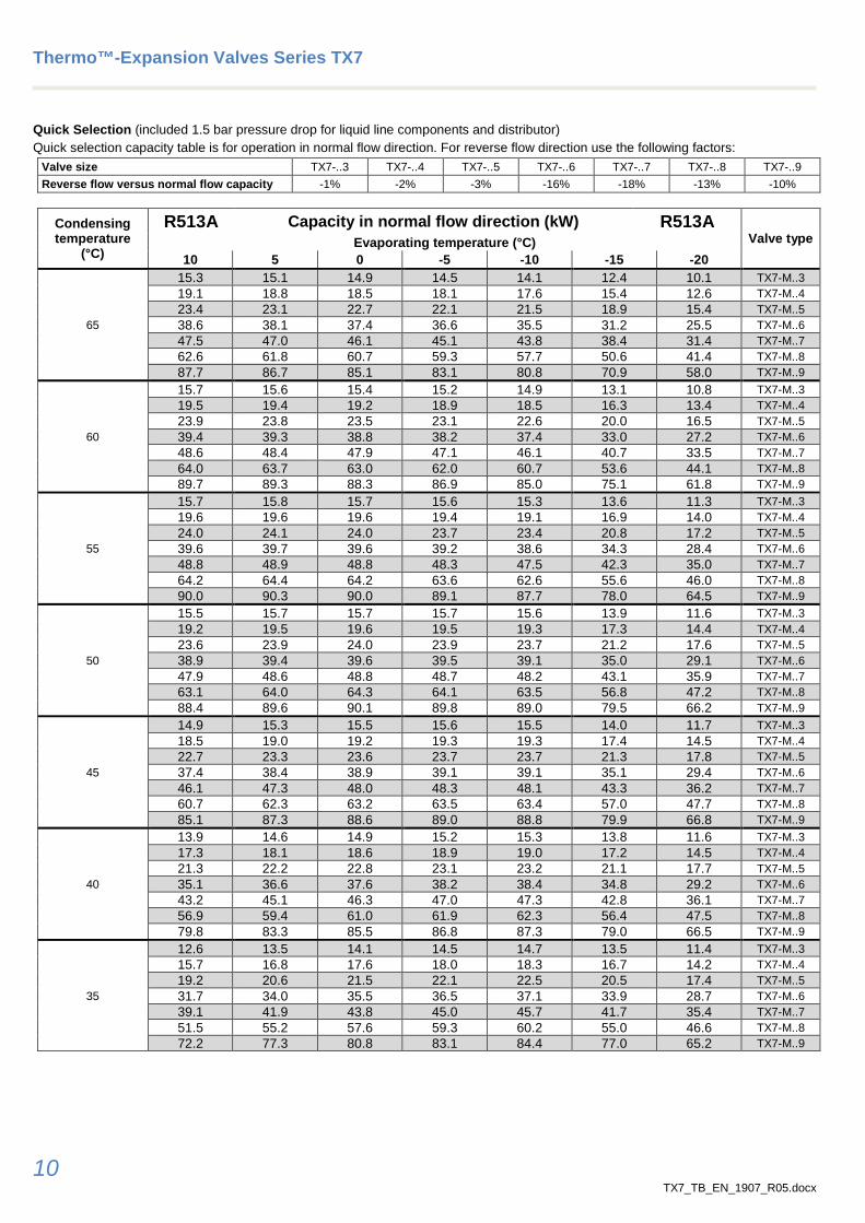
Quick Selection (included 1.5 bar pressure drop for liquid line components and distributor) Quick selection capacity table is for operation in normal flow direction. For reverse flow direction use the following factors:
Valve size TX7-..3 TX7-..4 TX7-..5 TX7-..6 TX7-..7 TX7-..8 TX7-..9 Reverse flow versus normal flow capacity -1% -2% -3% -16% -18% -13% -10%
Condensing temperature
(°C)
R513A Capacity in normal flow direction (kW) R513A Valve type Evaporating temperature (°C)
10 5 0 -5 -10 -15 -20
65
15.3 15.1 14.9 14.5 14.1 12.4 10.1 TX7-M..3 19.1 18.8 18.5 18.1 17.6 15.4 12.6 TX7-M..4 23.4 23.1 22.7 22.1 21.5 18.9 15.4 TX7-M..5 38.6 38.1 37.4 36.6 35.5 31.2 25.5 TX7-M..6 47.5 47.0 46.1 45.1 43.8 38.4 31.4 TX7-M..7 62.6 61.8 60.7 59.3 57.7 50.6 41.4 TX7-M..8 87.7 86.7 85.1 83.1 80.8 70.9 58.0 TX7-M..9
60
15.7 15.6 15.4 15.2 14.9 13.1 10.8 TX7-M..3 19.5 19.4 19.2 18.9 18.5 16.3 13.4 TX7-M..4 23.9 23.8 23.5 23.1 22.6 20.0 16.5 TX7-M..5 39.4 39.3 38.8 38.2 37.4 33.0 27.2 TX7-M..6 48.6 48.4 47.9 47.1 46.1 40.7 33.5 TX7-M..7 64.0 63.7 63.0 62.0 60.7 53.6 44.1 TX7-M..8 89.7 89.3 88.3 86.9 85.0 75.1 61.8 TX7-M..9
55
15.7 15.8 15.7 15.6 15.3 13.6 11.3 TX7-M..3 19.6 19.6 19.6 19.4 19.1 16.9 14.0 TX7-M..4 24.0 24.1 24.0 23.7 23.4 20.8 17.2 TX7-M..5 39.6 39.7 39.6 39.2 38.6 34.3 28.4 TX7-M..6 48.8 48.9 48.8 48.3 47.5 42.3 35.0 TX7-M..7 64.2 64.4 64.2 63.6 62.6 55.6 46.0 TX7-M..8 90.0 90.3 90.0 89.1 87.7 78.0 64.5 TX7-M..9
50
15.5 15.7 15.7 15.7 15.6 13.9 11.6 TX7-M..3 19.2 19.5 19.6 19.5 19.3 17.3 14.4 TX7-M..4 23.6 23.9 24.0 23.9 23.7 21.2 17.6 TX7-M..5 38.9 39.4 39.6 39.5 39.1 35.0 29.1 TX7-M..6 47.9 48.6 48.8 48.7 48.2 43.1 35.9 TX7-M..7 63.1 64.0 64.3 64.1 63.5 56.8 47.2 TX7-M..8 88.4 89.6 90.1 89.8 89.0 79.5 66.2 TX7-M..9
45
14.9 15.3 15.5 15.6 15.5 14.0 11.7 TX7-M..3 18.5 19.0 19.2 19.3 19.3 17.4 14.5 TX7-M..4 22.7 23.3 23.6 23.7 23.7 21.3 17.8 TX7-M..5 37.4 38.4 38.9 39.1 39.1 35.1 29.4 TX7-M..6 46.1 47.3 48.0 48.3 48.1 43.3 36.2 TX7-M..7 60.7 62.3 63.2 63.5 63.4 57.0 47.7 TX7-M..8 85.1 87.3 88.6 89.0 88.8 79.9 66.8 TX7-M..9
40
13.9 14.6 14.9 15.2 15.3 13.8 11.6 TX7-M..3 17.3 18.1 18.6 18.9 19.0 17.2 14.5 TX7-M..4 21.3 22.2 22.8 23.1 23.2 21.1 17.7 TX7-M..5 35.1 36.6 37.6 38.2 38.4 34.8 29.2 TX7-M..6 43.2 45.1 46.3 47.0 47.3 42.8 36.1 TX7-M..7 56.9 59.4 61.0 61.9 62.3 56.4 47.5 TX7-M..8 79.8 83.3 85.5 86.8 87.3 79.0 66.5 TX7-M..9
35
12.6 13.5 14.1 14.5 14.7 13.5 11.4 TX7-M..3 15.7 16.8 17.6 18.0 18.3 16.7 14.2 TX7-M..4 19.2 20.6 21.5 22.1 22.5 20.5 17.4 TX7-M..5 31.7 34.0 35.5 36.5 37.1 33.9 28.7 TX7-M..6 39.1 41.9 43.8 45.0 45.7 41.7 35.4 TX7-M..7 51.5 55.2 57.6 59.3 60.2 55.0 46.6 TX7-M..8 72.2 77.3 80.8 83.1 84.4 77.0 65.2 TX7-M..9
Thermo™-Expansion Valves Series TX7
11 TX7_TB_EN_1907_R05.docx
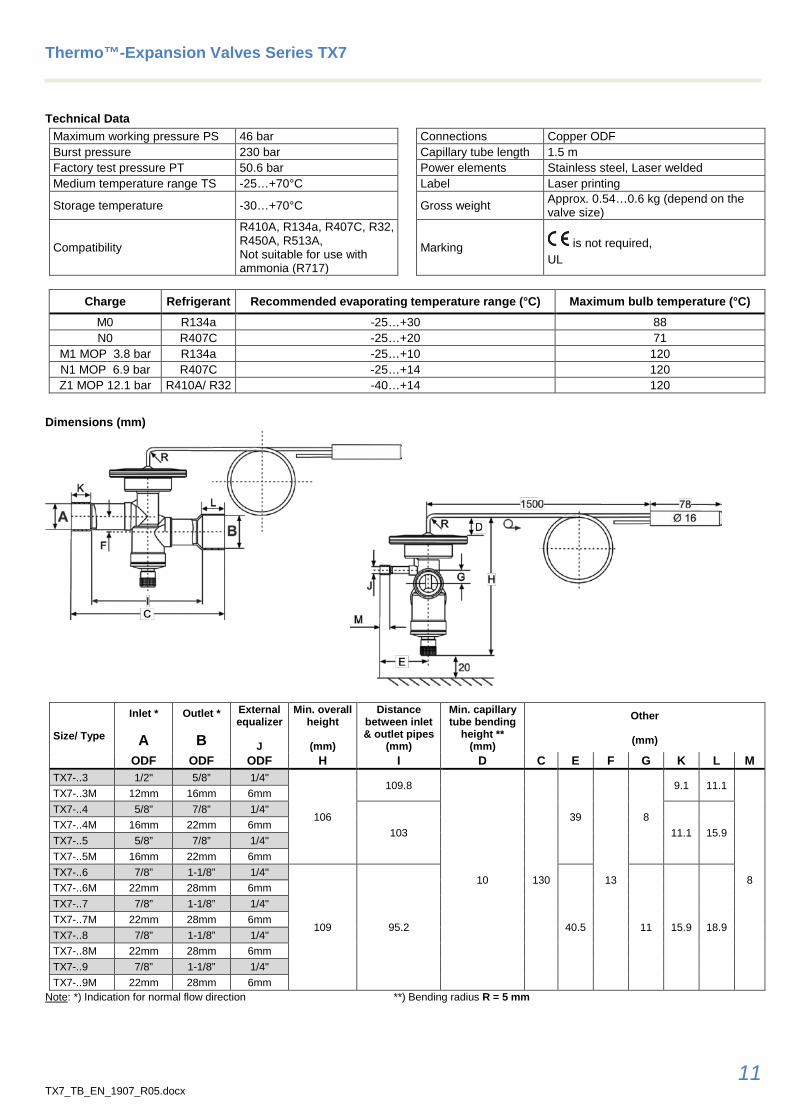
Technical Data Maximum working pressure PS 46 bar Connections Copper ODF Burst pressure 230 bar Capillary tube length 1.5 m Factory test pressure PT 50.6 bar Power elements Stainless steel, Laser welded Medium temperature range TS -25…+70°C Label Laser printing
Storage temperature -30…+70°C Gross weight Approx. 0.54…0.6 kg (depend on the valve size)
Compatibility
R410A, R134a, R407C, R32, R450A, R513A, Not suitable for use with ammonia (R717)
Marking is not required, UL
Charge Refrigerant Recommended evaporating temperature range (°C) Maximum bulb temperature (°C)
M0 R134a -25…+30 88 N0 R407C -25…+20 71
M1 MOP 3.8 bar R134a -25…+10 120 N1 MOP 6.9 bar R407C -25…+14 120 Z1 MOP 12.1 bar R410A/ R32 -40…+14 120
Dimensions (mm)
Size/ Type
Inlet *
A
Outlet *
B
External equalizer
J
Min. overall height
(mm)
Distance between inlet & outlet pipes
(mm)
Min. capillary tube bending
height ** (mm)
Other
(mm)
ODF ODF ODF H I D C E F G K L M TX7-..3 1/2" 5/8” 1/4"
106
109.8
10 130
39
13
8
9.1 11.1
8
TX7-..3M 12mm 16mm 6mm TX7-..4 5/8” 7/8” 1/4"
103 11.1 15.9 TX7-..4M 16mm 22mm 6mm TX7-..5 5/8” 7/8” 1/4" TX7-..5M 16mm 22mm 6mm TX7-..6 7/8” 1-1/8” 1/4"
109 95.2 40.5 11 15.9 18.9
TX7-..6M 22mm 28mm 6mm TX7-..7 7/8” 1-1/8” 1/4" TX7-..7M 22mm 28mm 6mm TX7-..8 7/8” 1-1/8” 1/4" TX7-..8M 22mm 28mm 6mm TX7-..9 7/8” 1-1/8” 1/4" TX7-..9M 22mm 28mm 6mm
Note: *) Indication for normal flow direction **) Bending radius R = 5 mm

TX7_TB_EN_1907_R05.docx Emerson Climate Technologies GmbH shall not be liable for errors in the stated capacities, dimensions, etc., as well as typographic errors. Products, specifications, designs and technical data contained in this document are subject to modification by us without prior notice. Illustrations are not binding. The Emerson Climate Technologies logo is a trademark and service mark of Emerson Electric Co. Emerson Climate Technologies Inc. is a subsidiary of Emerson Electric Co.