Embed Size (px)
Citation preview
7 2 PROCEEDINGS OF ELECTRIC FURNACE STEEL CONFERENCE, 1957
The paper will be presented by Mr. in the rolling mill, the blast furnace shop, Wayne, who has had considerable experi- and the open hearth shop, and for the past ence in the making of steel. He got his 17 years has worked in the electric furnace formal training a t Illinois Tech; joined melt shop. I am happy to present Mr. T . J. U. S. Steel in 1930 and has had experience Wayne.
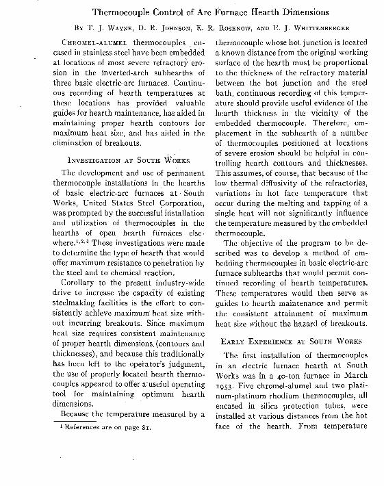
Thermocouple Control of Arc Furnace Hearth Dimensions
CHKOMEL-ALUMEL thermocouples . en- cased in stainless steel have been embedded a t locations of most severe refractory ero- sion in the inverted-arch subhearths of three basic electric-arc furnaces. Coritinu- ous recording of hearth temperatures a t these locations has provided valuable guides for hearth maintenance, has aided in maintaining proper hearth contours for maximum heat size, and has aided in the elimination of breakouts.
The development and use of permanent thermocouple installations in the hearths of basic electric-arc furnaces a t South Works, United States Steel Corporation, was prompted by the successful installation and utilization of thermocoupl6s in the hearths of open hearth furnaces else- w h e r e . ' ~ ~ , ~ Those investigations were made to determine the type of hearth that would offer maximum resistance to penetration by the steel and to chemical reaction.
Corollary to the present industry-wide drive to increase the capacity of existing steelmaking facilities is the effort to con- sistently achieve maximum heat size with- out incurring breakouts. Since maximum heat size requires consistent maintenance of proper hearth dimensions (contours and thicknesses), and because this traditionally has been left to the operator's judgment, the use of properly located hearth thermo- couples appeared to offer a useful operating tool for maintaining optimum hearth dimensions.
Because the temperature measured by a
1 References are on page 81.
thermocouple whose hot junction is located a known distance from the original working surface of the hearth must be proportional to the thickness of the refractory material between the hot junction and the steel bath, continuous recording of this temper- ature should provide useful evidence of the hearth thickness in the vicinity of the embedded thermocouple. Therefore, em- placement in thc subhearth of a number of thermocouples positioned a t locations of severe erosion should be helpful in con- trolling hearth contours and thicknesses. This assumes, of course, that because of the low thermal diffusivity of the refractories, variations in hot face temperature that occur during the melting and tapping of a single heat will not significantly influence the temperature measured by the embedded thermocouple.
The objective of the program to be de- scribed was to develop a method of em- bedding thermocouples in basic electric-arc furnace subhearths that would permit con- tinued recording of hearth temperatures. These temperatures would then serve as guides to hearth maintenance and permit the consistent attainment of maximum heat size without the hazard of breakouts.
The first installation of thermocouples in an electric furnace hearth a t South Works was in a 40-ton furnace in March 1953. Five chromel-alumel and two plati- num-platinum rhodium thermocouples, all encased in silica protection tubes, were installed a t various distances from the hot face of the hearth. From temperature
REFRACTORIES 73
measurements recorded a t these positions, mocouples and one 22-gauge chromel- an attempt was made to determine temper- alumel thermocouple. Each proprietary ature gradients through the hearth, and, assembly consists of a zo-gauge chromel- in addition, to determine approximate alumel thermocouplc embedded in mag-
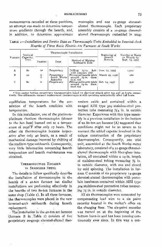
TABLE I-Installatio~z and Service Data on Ther?nocouple Uni ts Embedded i n I~zverted-Arch Hearths of Three Basic Electric-Arc Furnaces af South Works
a Two center bottom proprietary thermocouples failed by chemical attack after 234 and 30 heats, respec- tively. One sillimanite-encased replacement thermocouple is still operating satisfactorily after 748 heats.
Furnace
A
B
C
equilibrium temperatures for the cor- relation of the hearth condition with temperature.
I n this installation, one of the platinum- platinum rhodium thermocouples (closest to the hot face) burned out a t a temper- ature of 2030°F after only 17 heats. The other six thermocouples became inoper- ative after only 40 heats, as a result of mechanical damage incurred by shifting of the stadium-type subhearth. Consequently, very little information concerning hearth temperature and hearth maintenance was obtained.
Thermocouple Installation
Method of Making I Type Subhearth Hole
Nominal Capacity.
Tons
THERMOCOUPLES ENCASED IN STAINLESS STEEL
The details to follow specifically describe the installation of thermocouples in the hearth of a 40-ton furnace but similar installations are performing effectively in the hearths of two 80-ton furnaces in the same shop (Table I). I n all three furnaces, the thermocouples were placed in the new inverted-arch subhearth during hearth replacement.
~he ' instal la t ion in the 40-ton arc furnace (furnace B in Table I) consists of five proprietary zo-gauge chromel-alumel ther-
Hearth on Hearth by Burn-i" Sept. 15, 1957
nesium oxide and contained within a swaged AISI type 309 stainless-steel pro- tection tube measuring in. in outside diameter. Experience with this type assem- bly in a previous installation in the bottom of an 80-ton arc furnace (A) suggested that conditions might not be so severe as to warrant the added expense involved in the unique construction of the proprietary thermocouples. Consequently, one trial unit, assembled a t the South Works meter laboratory, consisted of a 22-gauge chromel- alumel thermocouple with fiber-glass insu- lation, a 1 contained within a 24-in. length of stainless-steel tubing measuring % in. in outside diameter, with one end closed by cold spinning. The installation in fur- nace C consists of six proprietary 14-gauge chromel-alumel thermocouples with porce- lain insulators contained within AISI type 304 stainless-steel protection tubes measur- ing jg in. in outside diameter.
All six thermocouples were connected by compensating lead wire to a six point recorder located in the melter's office on the charging floor. The six-point recorder was turned on a t the beginning of the bottom burn-in and has been running con- tinuously ever since. In this way a con-
80 ' 6. Proprietary
Proprietary South Works Assembly
Proprietary
40
80
5 I
6
Drilling $5-in. hole with masonry drill
Fitting subhearth brick around $$-in. diam steel rod
Fitting subhearth brick around $6-in. diam steel rod
NOV. 12, 1955
March 29. 1956
Oct. 14. 1956
1.012
460
532
74 PROCEEDINGS OF ELECTRIC FURNACE STEEL CONFERENCE, 1957
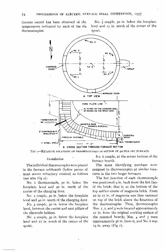
tinuous record has been obtained of the No. 5 couple, 30 in. below the foreplate temperature indicated by each of the six level and 2 7 in. north of the center of the thermocouples. spout.
WORKING DOOR
r N 0 . 6 THERMOCOUPLE
B. CROSS SECTION THROUGH FURNACE BOTTOM
1'1~ I-RELATIVE LOCATIONS OF THERMOCOUPLES I N BOTTOM OF 40-TON ARC FURNACE.
No. 6 couple, a t the center bottom of the furnace hearth.
Theindividualthermocoupleswereplaced The same identifying numbers were in the furnace subhearth (below points of assigned to thcrmocouples a t similar loca- most severe refractory erosion) as follows tions in the two larger furnaces. (see also Fig I) : The hot junction of each thermocouple
No. I thermocouple, 30 in. below the was positioned 9 in. back from the hot face foreplate level and 40 in. north. of the of the brick; that is, a t the bottom of the center of the charging door. top soldier course of magnesia brick. From
No. 2 couple, 30 in. below the foreplate 10 to 2 7 in. of magnesia was then rammed level and 40 in, south of the charging door. on top' of the brick above the locations of
No. 3 couple, 30 in. below the foreplate the thcrmocouples. Thus, thermocouples level, between the center and cast pillars of Nos. I , 2 , and 3 were located approximately the electrode holders. 2 7 in. from the original working surface of
N;. 4 couple, 30 in. below the forcplate the rammed hearth; Nos. 4 and 5 were level and 27 in. south of the center of the approximately 36 in. from it, and No. 6 was spout. 19 in. away (Fig I).
REFRACTORIES 7 5
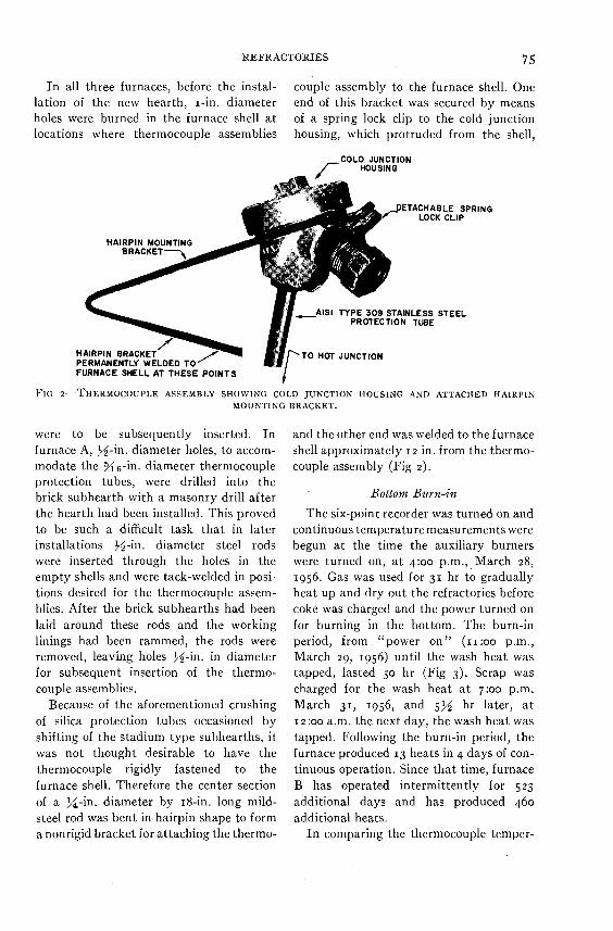
I n all three furnaces, before the instal- couple assembly to the furnace shell. One lation of the new hearth, I-in. diameter end of this bracket was secured by means holes were burned in the furnace shell a t of a spring lock clip to thc cold junction locations where thermocouple assemblies housing, which protruded from the shell,
COLD JUNCTION HOUSING
ETACHABLE SPRING LOCK CLIP
A l S l TYPE 3 0 9 STAINLESS STEEL PROTECTION TUBE
HAIRPIN BRACKET TO HOT JUNCTION PERMANENTLY WELDED T
FIG 2-THERMOCOUPLE ASSEMBLY SHOWING COLI) JUNCTION IIOUSING AND ATTACHED H A I R P I N
MOUNTING BRACKET.
wcrc to be subsequently inserted. I n furnace A, +$-in. diameter holes, to accom- modate the X6-in. diameter thermocouple protection tubes, were drilled into the brick subhearth with a masonry drill after the hearth had been installed. This proved to be such a difticult task that in later installations +$-in. diameter steel rods were inserted through the holes in the empty shells and were tack-welded in posi- tions desired for the thermocouple assem- blies. After the brick subhearths had been laid around these rods and the working linings had been rammed, the rods were removed, leaving holes )$-in. in diameter for subsequent insertion of the thermo- couple assemblies.
Because of the aforementioned crushing of silica protection tubes occasioned by shifting of the stadium type subhearths, i t was not thought desirable to have the thermocouple rigidly fastened to the furnace shell. Therefore the center section of a +/4-in. diameter by 18-in. long mild- steel rod was bent in. hairpin shape to form a nonrigid bracket for attaching the thermo-
and thc other end was welded to the furnace shell approximately 12 in. from the thermo- couple assembly (Fig 2).
Bottom Burn-in
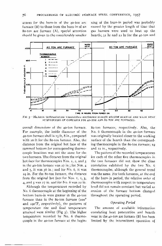
The six-point recorder was turned on and continuous temperature measurements were begun a t the time the auxiliary burners were turned on, a t 4:00 p.m., March 28, 1956. Gas was used for 31 hr to gradually heat up and dry out the refractories before coke was charged and the power turned on for burning in the bottom. The burn-in period, from "power on" (11:oo p.m., March 29, 1956) until the wash heat was tapped, lasted 50 hr (Fig 3). Scrap was charged for the wash heat a t 7:00 p.m. hlarch 31, 1956, and 546 hr later, a t 12:oo a.m. the next day, the wash heat was tapped. Following the burn-in period, the furnace produced 13 heats in 4 days of con- tinuous operation. Since that time, furnace B has operated intermittently for 523 additional days and has produced 460 additional heats.
I n comparing the thermocouple temper-
7 6 PROCEEDINGS OF ELECTRIC FURNACE STEEL CONFERENCE, 1957
alures for the burn-in of the 40-ton arc ning of thc burn-in period was probably furnace (B) to those from the burn-in of an caused by the greater length of time that 80-ton arc furnace (A), special attcntion gas burners were used to heat up the should bc given to the considcrably smaller hearth; 31 hr and 12 hr for the 40-ton and
TIYE IY HOUR6 FROM POWER OM
FIG S - ~ ~ E A R T H TEMPERATURE VARIAILOL\~< RECORDED DURING BOTTOM BURN-IN AND WA.jH H E U
AT BEGINNING OF CAMPAIGN FOR 40-TON AND &TON ARC FURNACES.
overall dimensions of Lhe 40-ton furnace. For example, the inside diameter of thc 40-ton furnace shell is 15 ft, 8 in., compared with 20 f t for the 80-ton furnace. Also, thc distance from the original hot face of the rammed bottom for corresponding thermo- couple locations was not the same for the two furnaces. The distance from the original hot face lor thermocouples Nos. I , 2 , and 3 in the 40-ton furnace was 27 in.; for Nos. 4 and 5, it was 36 in.; and for No. 6, it was 19 in. For the 80-ton furnace, the distancc from the original hot face for Nos. I, 2 , 3, 4, and 5 was 27 in. and for No. 6 was 2 2 in.
Although the temperatures recorded by No. 6 thermocouple a t the beginning of the bottom burn-in were greater in the 40-ton furnace than in the 80-ton furnace (100' and lgo°F, respectively), the patterns of temperature rise and final temperature attained were similar (Fig 3). The higher temperature recorded by No. 6 thermo- couple in the 40-ton furnace a t the begin-
80-ton furnaces, respectively. Also, the No. 6 thermocouple in the 40-ton furnace was originally located closer to the working surface of the hearth than the correspond- ing thermocouple in the 80-ton furnace; 19 and 2 2 in., respcctively.
'I'he pattern of the recorded temperatures for each of the other five thermocouples in the two furnaces did not show the close correlation exhibited by the two No. 6 thermocouples, although the general trend was the same. For both furnaces, a t the end of the burn-in period, the relative order of thermocouples with respect to temperature level did not remain constant but varied as erosion of the furnace bottom changed throughout the operating period.
Operati~tg Period
The amount of available information correlating heat penetration and hearth wear in the 40-ton arc furnace (B) has been limited by the intermittent operation of
REFRACTORIES 7 7
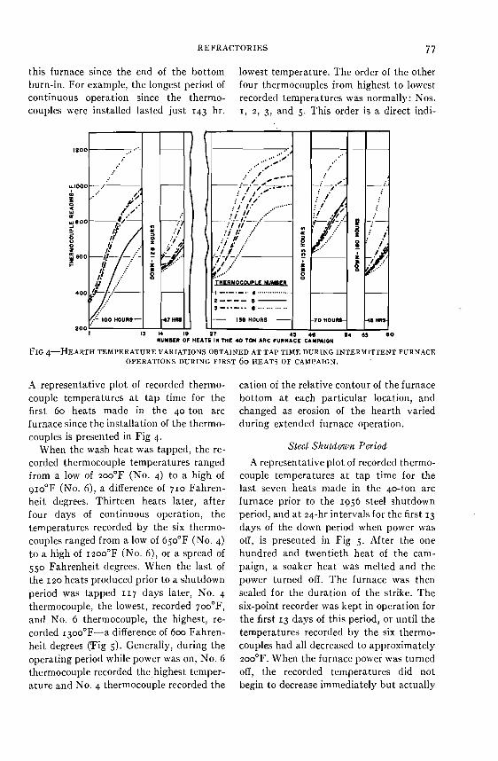
this furnace since the end of the bottom lowest temperature. The order of the other burn-in. For example, the longest period of four thermocouples from highest to lowest continuous operation since the thermo- recorded temperatures was normally: Nos. couples were installed lasted just 143 hr. I , 2, 3, and 5. This order is a direct indi-
FIG 4-HEARTH TI: s MPEKATURE VARIATIONS OBTAINED A T TAP TIME DURING INTERMITTENT FURNACE OPERATIONS DURING FIRST 60 HEATS OF CAMPAIGN.
A representative plot of recorded thermo- couple temperatures a t tap time for the first 60 heats made in the 40-ton arc furnace since the installation of the thermo- couples is presented in Fig 4.
When the wash heat was tapped, the re- corded thermocouple temperatures ranged from a low of 2o0°F (NO. 4) to a high of 9 ~ 0 ° F (No. 6), a difference of 710 Fahren- heit degrees. Thirteen heats later, after four days of continuous operation, the temperatures recorded by the six thermo- couples ranged from a low of 650°F (No. 4) to a high of 12oo"F (No. 6), or a spread of 550 Fahrenheit degrees. When the last of the 1 2 0 heats produced prior to a shutdown period was tapped 117 days later, No. 4 thermocouple, the lowest, recorded 7o0°F, and No. 6 thermocouple, the highest, re- corded I~ooOF-a difference of 600 Fahren- heit degrees (Fig 5). Generally, during the operating period while power was on, No. 6 thermocouple recorded the,highest temper- ature and No. 4 thermocouple recorded the
cation of the relative contour of the furnace bottom a t each particular location, and changed as erosion of the hearth varied during extended furnace operation.
Sleel SI~rrldown Period
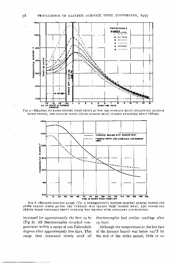
A representative plot of recorded thermo- couple temperatures a t tap time for the last seven heats made in the 40-ton arc furnace prior to the 1956 steel shutdown period, and a t 24-hr intervals for the first 13 days of the down period when power was off, is presented in Fig 5. After the one hundred and twentieth heat of the cam- paign, a soaker heat was melted and the power turned off. The furnace was then sealed for the duration of the strike. The six-point recorder was kept in operation for the first 13 days of this period, or until the temperatures recorded by the six thermo- couples had all decreased to approximately 200°F. When the furnace power was turned off, the recorded temperatures did not begin to decrease immediately but actually
7 c3 PROCEEDINGS O F ELECTRIC FURNACE STEEL CONFERENCE, 1957
114 116 116 120 1 2 1 4 5 6 7 e lo 11 12 13 NO. OF HEATS IN FURNACE
CAMPAION DOWN TIME -DAIS
FIG 5-HEATING U1' RATES DURING FIRST SEVEN 40-TON ARC FURNACE HEATS FOLLO\VING 50-HOUR DO\IIN PERIOD, AND COOLING RATES (WITII SOAKER HEAT) DURING EXTENDED DOWN PERIOD.
- FURNACE SEALED WITH SOAKER HEAT
T I AND UIISEALED. 0 1 9 BURNER
L
C
o 12 2 4 3 6 4 0 60 1 2 04 ee me 120 132 144 ue lee leo lez TIYE IN HOURS FROM PGWER OFF
FIG 6-HEARTH COOLING RATES (NO. 6 THERMOCOUPLE BOTTOM CENTER) DURING POWER-OFF DOWN PERIOD WHEN 40-TON ARC FURNACE WAS SEALED WITH SOAKER HEAT, AND PO\tlER-OFF PERIOD WHEN UNSEALED EMPTY FURNACE WAS HEATED WITH AUXILIARY GAS BURNERS.
increased,for approximately the first 2 4 hr thermocouples had similar readings after (Fig 6). All thermocouples recorded tem- 13 days. peratures within a range of IOO Fahrenheit Although the temperature at the hot face degrees after approximately five days. This of the furnace hearth was below 2 1 z ° F by range then decreased slowly unti l all the end of the strike period, little or no
REFRACTORIES 79
damage was caused by hydration of the re- clearly indicates that, as the length of time fractory lining. Apparently the protection the furnace remained out of service in- afforded by the soaker heat over an ex- creased, the auxiliary burners in the un- tended down period is adequate to prevent sealed furnace were better able to check the
THERMOCOUPLE
1 4 0 0 . I -'-.-.- 2--- - -
1200 - . ' .............. 5-
- 0
5 0
a z
I 121 122 123 124 I 20 126 121 126 129 130 I31 132 I33 134 130 136 137 130
NUMBER OF HEATS IN THE 4 0 TON ARC FuRNACE CAMPbJON
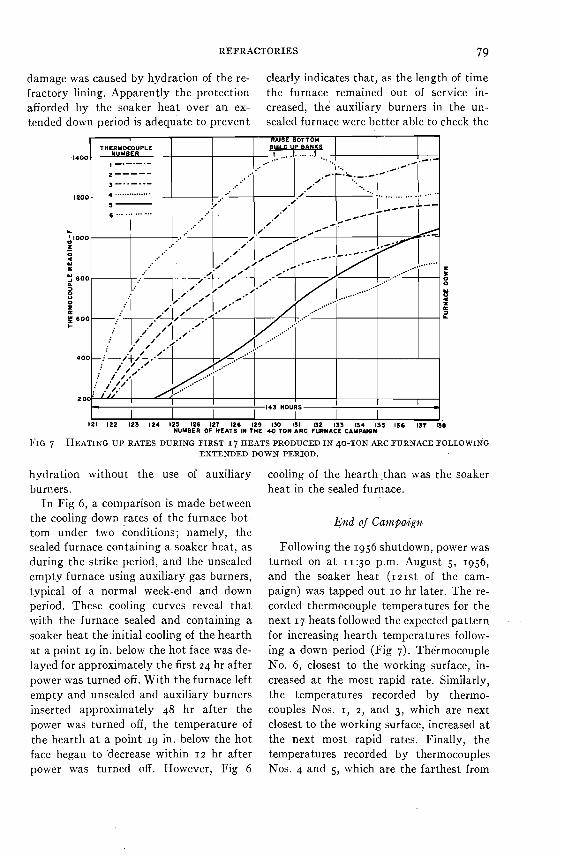
FIG ?-HEATING UI' RATES DURING FIRST I7 HEATS PRODUCED I N 40-TON ARC FURNACE FOLLOWING EXTENDED DOWN PERIOD.
hydration without the use of auxiliary cooling of the hearth .than was the soaker burners. heat in the sealed furnace.
I n Fig 6, a co~nparison is made between the cooling down rates of the furnace bot- End o j Ca?npaign tom under two conditions; namely, the sealed furnace containing a soaker heat, as Following the 1956 shutdown, power was during the strike period, and the unsealed turned on a t 11:3o p.m. August 5, 1956, empty furnace using auxiliary gas burners, and the soaker heat (121st of the cam- typical of a normal week-end and down paign) was tapped out 10 hr later. The re- period. These cooling curves reveal that corded thermocouple temperatures for the with the furnace sealed and containing a next 17 heats followed the expected pattern . soaker heat the initial cooling of the hearth for increasing hearth temperatures follow- a t a point 19 in. below the hot face was de- ing a down period (Fig 7). Thermocouple layed for approximately the first 24 hr after No. 6, closest to the working surface, in- power was turned off. With the furnace left creased a t the most rapid rate. Similarly, empty and unsealed and auxiliary burners the temperatures recorded by thermo- inserted approximately 48 hr after the couples Nos. I, 2, and 3, which are next power was turned off, the temperature of closest to the working surface, increased a t the hearth a t a point 19 in. below the hot the next most rapid rates. Finally, the face began to 'decrease within 12 hr after temperatures recorded by thermocouples power was turned off. However, Fig 6 Nos. 4 and 5, which are the farthest from
80 PROCEEDINGS OF ELECTRIC FURNACE STEEL CONFERENCE, 1957
the working surface, increased a t the lowest rates (Fig 7).
When the 130th heat of the furnace cam- paign was tapped, No. 6 thermocouple recorded a temperature approximately r400°F. This has also been found for the 80-ton arc furnaces A and C, and has arbi- trarily been chosen as the maximum allow- ahle working temperature a t any one of the six thermocouple locations. As a result, additional maintenance time was spent following the next few heats to raise the bottom and build up the banks with double-burned dolomite fettling material (Fig 7 ) After the 133rd heat of the cam- paign had been tapped, the recorded tem- perature of the No 6 thermocouple began to decrease, and by the 135th heat it had reached an equilibrium level of 12ooOF. The rapid rate of temperature rise a t the No. I
thermocouple location was also checked by the refractory maintenance.
After 138 heats, the furnace was again taken off. The temperatures recorded by thermocouples Nos. 3, 4, and 5 were still rising and apparently had not reached equilibrium level.
Tizermocouple Performance
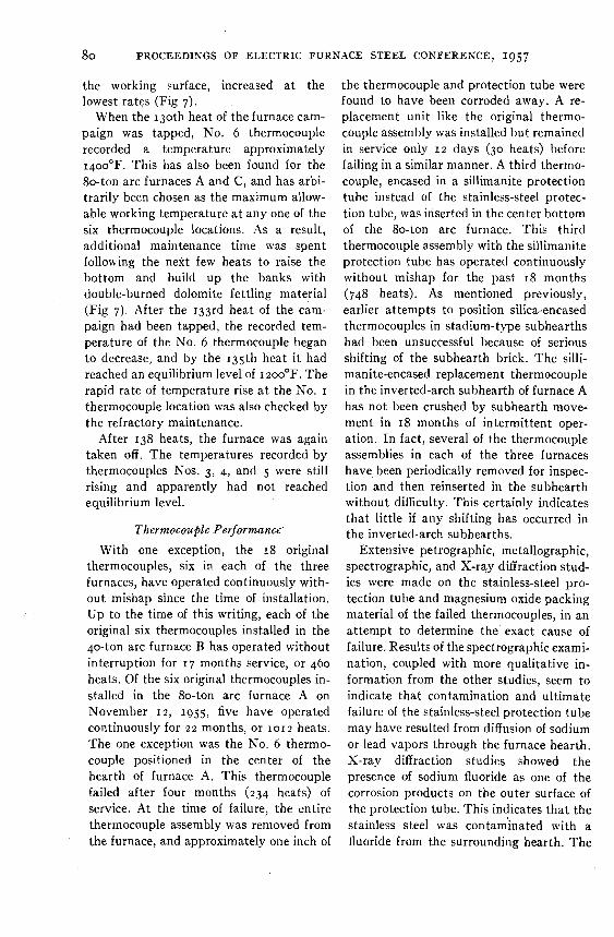
With one exception, the 18 original thermocouples, six in each of the three furnaces, have operated continuously with- out mishap since the time of installation. Up to the time of this writing, each of the original six thermocouples installed in the 40-ton arc furnace B has operated without interruption for 17 months service, or 460 heats. Of the six original thermocouples in- stalled in the 80-ton arc furnace A on November 12, 1955, five have operated continuously for 2 2 months, or 1012 heats. The one exception was the No. 6 thermo- couple positioned in the center of the hearth of furnace A. This thermocouple failed after four months (234 heats) of service. At the time of failure, the entire thermocouple assembly was removed from the furnace, and approximately one inch of
the thermocouple and protection tube were found to have been corroded away. A re- placement unit like the original thermo- couple assembly was installed but remained in service only 12 days (30 heats) before failing in a similar manner. A third thermo- couple, encased in a sillimanite protection tube instead of the stainless-steel protec- tion tube, was inserted in the center bottom of the 80-ton arc furnace. This third thermocouple assembly with the sillimanite protection tube has operated continuously without mishap for the past 18 months (748 heats). As mentioned previously, earlier attempts to position silica-encased thermocouples in stadium-type subhearths had been unsuccessful because of serious shifting of the subhearth brick. The silli- manite-encased replacement thermocouple in the inverted-arch subhearth of furnace A has not been crushed by subhearth move- ment in 18 months of intermittent oper- ation. In fact, several of the thermocouple assemblies in each of the three furnaces have, been periodically removed for inspec- tion and then reinserted in the subhearth without difficulty. This certainly indicates that little if any shifting has occurred in the inverted-arch subhearths.
Extensive petrographic, metallographic, spectrographic, and X-ray diffraction stud- ies were made on the stainless-steel pro- tection tube and magnesium oxide packing material of the failed thermocouples, in an attempt to determine the' exact cause of failure. Results of the spectrographic exami- nation, coupled with more qualitative in- formation from the other studies, seem to indicate that contamination and ultimate failure of the stainless-steel protection tube may have resulted from diffusion of sodium or lead vapors through the furnace hearth. X-ray diffraction studies showed the presence of sodium fluoride as one of the corrosion products on the outer surface of the protection tube. This indicates that the stainless steel was contam'inated with a fluoride from the surrounding hearth. The
REFRACTORIES 81
fluoride might possibly have come from the 2. Sosma"? B. : Trans. AIME (r948-Met. Tech., Aug.) 176.
refractory mortar used in the hearth. This 3. Snow, R. B . : Iron Age (Feb. 2. 1951) 167, condition has not occurred a t any of the 103-rob; (Feb. 8. 1951) 167, 98-100.
other thermocouple positions. DISCUSSION
SUMMARY P. R. GOUWENS, C H A I R X A N - T ~ ~ ~ ~ you, Mr. Wayne. There are two formal
Six chromel-alumel thermocou~les were discussions to this paper, the first by Mr. installed a t strategic locations in the in- L,, ~ ~ l ~ ~ ~ , of Timken ~ ~ l l ~ ~ ~~~~i~~ co. verted-arch type subhearths of three basic M ~ , ~ ~ l ~ ~ ~ . electric-arc furnaces to record hearth tem- peratures throughout the furnace cam- TIMKEN ROLLER BEARING RESULTS paign. These thermocou~le temperature L . E . HOLMES-We agree with the find- measurements are being used 's guides '0 ings of the report presented by ~ r . Wayne, bottom to augment the although we have accomplished the same furnace personnel's experienced visual result in a different manner. observations. In September of 1952, the Timken Roller
Admittedly, it is difficult to maintain . Bearing Co. put into operation a zo-ft, Ininimum hearth refractory thicknesses 85-ton top-charge electric-arc furnace. As and yet retain a factor Of when de- accessory equipment, i t had the first elec- pending On the human eye. The rela- tromagnetic induction stirrer to be used on tion Of bank thickness to bottom an electric-arc furnace in this country. often promotes a misleading impression. This equipment, mounted directly under
The inverted-arch hearth construction the furnace, represented an investment of was designed to increase the furnace capaci- approximately $zoo,ooo. ties an average Of 5 tons per heat. Through Although the furnace shell and hearth the use of hearth thermocou~les, it has were designed to provide maximum safety been possible to minimize the use of fettling to the stirrer and equipment, the danger of materials and a t the same time maintain a breakthrough of molten metal was a con- desirable bottom and bank thicknesses. stant threat, It was imperative that we Thus, the added S-ton potential has been protect the stirrer and provide some fore- surpassed and an 8-ton increase is being warning of a breakthrough. attained. Therefore, zo resistor-type thermometers
temperatures Of loooO to were bolted to the stainless-steel bottom IZOOOF are considered normal. However, plate in a uniform pattern covering the concern is not expressed until a level of area above the stirrer. The resistor ther- 1400°F has been reached. Then, after mometers in turn were connected to a tapping, slightly heavier fettling of double- millivolt meter on the main floor, The burned dolomite is concentrated in the hot thermometers were a delicate device and face area in the vicinity of the high-reading were not designed for this rugged task. thermocouples. They failed rapidly and, because of their
Except for an occasional break- high cost, yet low efficiency, a new method out, no difficulty has been experienced with had to be found. banks or bottoms since the inception of the First attempts to install a thermocouple recording system. between the stirrer and bottom shell failed
REFERENCES because of the strong field of the induction stirrer. This was rectified by the use of a
I . Franz, A. F . : Open Hearth Proc., AIME (1938) 21, 17-22. thermocouple with some innovations. A
82 PROCEEDINGS OF ET.ECTKIC FURNACE STEEL CONFERENCE, 1957
24-gauge iron-constantan thermocouple covered with a braided glass protective covering was installed. The secret of the couple was that it had a continuing twist per length of the thermocouple. With this tight twist, and by dampening the sensi- tivity of the recording instrument, we have had four years of trouble-free operation.
The thermocouples were installed in a manner that would enable us to maintain them with minimum effort and delay, by fastening them to a steel cable that was drawn taut across the bottom of the fur- nace. The thermocouples were then secured to a trunk line leading to the recording instrument on the main floor.
Mr. Wayne reported that their center thermocouple recorded the hottest tem- perature. The same thing is true with our system. When our hearth is in good condi- tion and is a t the proper thickness, the recorded readings vary from 6o0°F in the center to 3o0°F a t the edge of the bottom shell. When a hot spot develops, a definite indication is recorded. To aid the furnace personnel, the recorder is preset to 7 jo°F, and a red light indicates any thermocouple that has exceeded this setting. Although this is not a dangerous temperature, it is a definite indication that some part of the hearth is thin and needs proper repair when the bottom is made up. I We have been pleased with the success
of our operation, and we definitely feel that the thermocouple is a good gauge in main- taining a furnace hearth.
P. R . GOUWENS, CHAIRMAN-The next discussion will be presented by Mr. R . A. Hedin, electrical engineer with the Republic Steel Corporation, Canton, Ohio.
R. A. HEDIN-Inasmuch as the ma- jority of Republic's experience in the Cen- tral Alloy District on the use of thermo- couples for bottom furnace protection covers a span of only the past few years, I
do not consider myself really well qualified to discuss the merits of the type of installa- tion Mr. Wayne has so ably described in his paper. That installation offers another line of approach to the problem in addition to the three different types of installations now used a t Republic. We have expended considerable time and money on these, and feel that \ye could benefit from the experi- ence U. S. Steel has acquired.
One of Republic's installations was de- scribed by D . G. Harris* in I9j3 and this discussion will add a brief description of the most recent installation.
These methods evolved around an induc- tion stirrer that was installed on one of two new So-ton top-charge electric furnaces in No. 3 melt shop. With this costly electrical equipment beneath the furnace, it was essential to have a reliable thermocouple that would protect the stirrer against a furnace breakout.
The furnace shell directly above the stirrer consists of seven nonmagnetic 3-in. thick stainless-steel slabs. Before the fur- nace shell was lined, zo individual copper plates were placed side by side on top of these stainless slabs. Attached to each copper plate was a %-in, diameter copper bolt, which extended approximately in. below the furnace bottom, through one of the 2 0 holes that had been drilled in the stainless slabs. Attached to each of these copper bolts was a 100-ohm platinum resistor. The lead wire, consisting of a single copper conductor packed in mag- nesium oxide and enclosed in a copper sheath, extended from each of the resistors to a system of temperature alarm relays, a no-point indicating pyrometer and a no-point recording pyrometer.
As soon as this installation had been completed and the burning in of the furnace
* Harris, D. G.: Measurement of Bottom Shell Temperature. Elec. Fzir. Steel Pr06., A I M E (1953) 1 1 , 91.
REFRACTORIES 83
bottom started, the equipment ivas put into operation. After co~npletion of the bottom burn-in period and the first few heats, temperatures indicated on the rccording equipment had lcveled off over a range of 2o0°F to 900°F. As this installation is on a Aat-bottomed furnace, the wide range of temperatures is not unusual. I n fact, it was almost possible to plot the contour of the furnace hearth a t the bath line from the temperatures indicated, the highest, temperature being in the center of the furnace, where the lining is thinnest, and gradually cooler temperatures where the lining increased in thickness toward both the spout and charge door.
I t might be worth while to mention that while the furnace was in operation and the induction stirrer in use, it was necessary to turn off this 20-point recorder because the lead wire between the stirrer and furnace bottom was subjected to the half-cyclc magnetic field generated by the stirrer This exceptionally lo\+ frequency induced cnough of an alternating current voltage in the recorder to cause the recorder pen to oscillate during the entire stirring opera- tion, thereby making i t almost impossible to distinguish one point from another on the recorder.
Although the recorder was inoperative during the stirring cycle, the 20-point indi- cating pyromctcr and the system of alarm relays affordcd ample protection, as thcir operation was not affccted by the induced voltages in the lead wire.
This system operated successfully for about 18 months. Toward the end of the period, sevcral of the 2 0 measuring points indicated eithcr grounds or open circuits in the lead wire. During the next scheduled relining, a portion of the bottom was rcmoved, and it was found that the copper plates were very badly eroded and oxidized. I n two, owing to either shifting of the ,
furnace hearth or expansion and contrac- tion of thc furnace bottom plates, the copper bolts had been sheared off. The lead
wire had been badly damaged. I n many places, the copper sheath had been com- pletely eroded away, permitting the mag- nesium oxide insulation to fall away from the inner conductor. Since the sheath was one part of the electrical circuit, this explained the resistors that indicated an open circuit when tcs,ted.
Several months later, this same basic system was re-installed with what are believed to be substantial improvements. Twenty copper plates similar in design to the originals were installed in the same manner. These new plates were silver- plated, with the idea that the protective plating would, to some extent, prevent oxidation and eroding. An improved 100-ohm platinum resistor, molded in a high-tcrnperature glass case, was attached to the extended copper bolt in essentially the same manner as the original installa- tion. A type 304 stainless steel-sheathed lead wire, consisting of two copper con- ductors embedded in magnesium oxide insulation, was attached to the recording equipment.
Also installed was a group of conventional iron-constantan thermocouples, which were conncctcd to a second multiple-point recordcr.
This type of couple had not been con- sidercd earlier bccause of the problems that arose during the stirring cycle. The couple selectcd was iron-constantan lcad wire embeddcd in magnesium oxide insulation in a typc 304 stainless-steel sheath, with the hot junction sealed in one end of the lead wire and insulated from the sheath.
Twenty of the couples were installed, each hot junction end being insertcd in a %-in. diameter by a 135-in. deep hole that had been drilled in the under side of the furnace bottom. The lead wire was then extended from the under side of the furnace to the recorder.
84 PROCEEDINGS OF ELECTRIC FURNACE STEEL CONFERENCE, 1957
Once again the temperatures indicated by these two systems were much the same as with the first installation. The resistors connected to the copper bolts indicated temperatures over a range of from zoo°F to goo°F, while the thermocouples installed in the furnace bottom indicated tempera- tures over a range of zoo°F to 7o0°F.
Again it was almost possible to plot the contour of the hearth line, as the tempera- tures.varied directly as the distance from the furnace bottom to the bath.
As of this writing (November 1957), the present installations have been in operation approximately 18 months, the system using the conventional thermocouples giving more reliable service .than the platinum resistor installation, because of its rugged- ness and simplicity.
P. R. G o u w ~ ~ s , CHAIRMAN-Thank you, Mr. Hedin, for your contribution. We shall have to defer any questions until later, since we are ;unning a.little short on
time. I would like to thank Mr. Wayne, Mr. Holmes and Mr. Hedin for their excellent contributions to this session.
Now I will turn the meeting back to Mr. Scheid.
A . J . Sclzeid, J r . , presiding
A. J . SCHEID, JR., CHAIRMAN-OUT next paper will be presented by Mr. L . A. Stoyell, of the Fine Metals and Chemicals Department of Electro Metallurgical Com- pany, Niagara Falls, N . Y. His 50-author is Mr. T. R. Culbert, Student a t the Case Institute of Technology.
Mr. Stoyell joined the Electro Metal- lurgical Company in 1940, went back to Lehigh to get a little more metallurgy, and then rejoined EM in 1948. He is now in charge of manufacturing for fine metals and chemicals; so that I believe he is well qualified to tell you about one of his latest, a self-baking refractory mix. I am happy to present Mr. L. A. Stoyell, who will talk to us about a special refractory for ladlcs.