Embed Size (px)
Citation preview
User
Manual
Thermocouple/Millivolt InputModule
(Cat. No. 1794IT8)
AllenBradley
Because of the variety of uses for the products described in thispublication, those responsible for the application and use of this controlequipment must satisfy themselves that all necessary steps have beentaken to assure that each application and use meets all performance andsafety requirements, including any applicable laws, regulations, codesand standards.
The illustrations, charts, sample programs and layout examples shown inthis guide are intended solely for example. Since there are manyvariables and requirements associated with any particular installation,Allen-Bradley does not assume responsibility or liability (to includeintellectual property liability) for actual use based upon the examplesshown in this publication.
Allen-Bradley publication SGI–1.1, “Safety Guidelines For TheApplication, Installation and Maintenance of Solid State Control”(available from your local Allen-Bradley office) describes someimportant differences between solid-state equipment andelectromechanical devices which should be taken into considerationwhen applying products such as those described in this publication.
Reproduction of the contents of this copyrighted publication, in whole orin part, without written permission of Allen–Bradley Company, Inc.is prohibited.
Throughout this manual we make notes to alert you to possible injury topeople or damage to equipment under specific circumstances.
!ATTENTION: Identifies information about practices orcircumstances that can lead to personal injury or death,property damage, or economic loss.
Attention helps you:
• identify a hazard
• avoid the hazard
• recognize the consequences
Important: Identifies information that is especially important forsuccessful application and understanding of the product.
Important: We recommend you frequently backup your applicationprograms on appropriate storage medium to avoid possibledata loss.
DeviceNet, DeviceNetManager, and RediSTATION are trademarks of Allen-Bradley Company, Inc.PLC, PLC–2, PLC–3, and PLC–5 are registered trademarks of Allen-Bradley Company, Inc.Windows is a trademark of Microsoft.Microsoft is a registered trademark of MicrosoftIBM is a registered trademark of International Business Machines, Incorporated.
All other brand and product names are trademarks or registered trademarks of their respective companies.
Important User Information

Using This Manual P-1. . . . . . . . . . . . . . . . . . . . . . . . . . . . . . .
Preface Objectives P-1. . . . . . . . . . . . . . . . . . . . . . . . . . . . . . . . . . .
Audience P-1. . . . . . . . . . . . . . . . . . . . . . . . . . . . . . . . . . . . . . . . . .
Vocabulary P-1. . . . . . . . . . . . . . . . . . . . . . . . . . . . . . . . . . . . . . . .
What This Manual Contains P-1. . . . . . . . . . . . . . . . . . . . . . . . . . . .
Conventions P-2. . . . . . . . . . . . . . . . . . . . . . . . . . . . . . . . . . . . . . .
For Additional Information P-2. . . . . . . . . . . . . . . . . . . . . . . . . . . . . .
Summary P-2. . . . . . . . . . . . . . . . . . . . . . . . . . . . . . . . . . . . . . . . .
Overview of Flex I/O and your Thermocouple/mV Module 1-1.
Chapter Objectives 1-1. . . . . . . . . . . . . . . . . . . . . . . . . . . . . . . . . . .
The FLEX I/O System 1-1. . . . . . . . . . . . . . . . . . . . . . . . . . . . . . . . .
How FLEX I/O Analog Modules Communicate with Programmable Controllers 1-1. . . . . . . . . . . . . . . . . . . . . . . . . . .
Typical Communication Between an Adapter and a Module 1-2. . . .
Features of your Modules 1-3. . . . . . . . . . . . . . . . . . . . . . . . . . . . . .
Chapter Summary 1-3. . . . . . . . . . . . . . . . . . . . . . . . . . . . . . . . . . .
How to Install Your Thermocouple/mV Input Module 2-1. . . . .
Before You Install Your Input Module 2-1. . . . . . . . . . . . . . . . . . . . . .
European Union Directive Compliance 2-1. . . . . . . . . . . . . . . . . . . . .
EMC Directive 2-1. . . . . . . . . . . . . . . . . . . . . . . . . . . . . . . . . . . .
Low Voltage Directive 2-2. . . . . . . . . . . . . . . . . . . . . . . . . . . . . . .
Power Requirements 2-2. . . . . . . . . . . . . . . . . . . . . . . . . . . . . . . . .
Wiring the Terminal Base Units (1794TB2 and TB3 shown) 2-3. . .
Installing the Module 2-4. . . . . . . . . . . . . . . . . . . . . . . . . . . . . . . . . .
Connecting Wiring for the Thermocouple/mV Module 2-5. . . . . . . . . .
Table 2.A Wiring connections for the 1794IT8 Thermocouple Input Module 2-6. . . . . . . . . . . . . . . . . . . . . . . . . . . . . . . . . . . .
Example of Millivolt Input Wiring to a 1794TB3Terminal Base Unit 2-7. . . . . . . . . . . . . . . . . . . . . . . . . . . . . .
Example of 3wire Thermocouple Wiring to a 1794TB3T Temperature Terminal Base Unit 2-7. . . . . . . . . . . . . . . . . . . . .
Module Indicators 2-8. . . . . . . . . . . . . . . . . . . . . . . . . . . . . . . . . . . .
Chapter Summary 2-8. . . . . . . . . . . . . . . . . . . . . . . . . . . . . . . . . . .
Table of Contents
Table of Contentsii
Module Programming 3-1. . . . . . . . . . . . . . . . . . . . . . . . . . . .
Chapter Objectives 3-1. . . . . . . . . . . . . . . . . . . . . . . . . . . . . . . . . . .
Block Transfer Programming 3-1. . . . . . . . . . . . . . . . . . . . . . . . . . . .
Sample programs for FLEX I/O Analog Modules 3-2. . . . . . . . . . . . . .
PLC3 Programming 3-2. . . . . . . . . . . . . . . . . . . . . . . . . . . . . . . .
Figure 3.1 PLC3 Family Sample Program Structure 3-2. . . . . . . . . . . . . . . .
PLC5 Programming 3-3. . . . . . . . . . . . . . . . . . . . . . . . . . . . . . . .
Figure 3.2 PLC5 Family Sample Program Structure 3-3. . . . . . . . . . . . . . . .
PLC2 Programming 3-4. . . . . . . . . . . . . . . . . . . . . . . . . . . . . . . .
Chapter Summary 3-4. . . . . . . . . . . . . . . . . . . . . . . . . . . . . . . . . . .
Writing Configuration to and Reading Status from your Module with a Remote I/O Adapter 4-1. . . . . . . . . . .
Chapter Objectives 4-1. . . . . . . . . . . . . . . . . . . . . . . . . . . . . . . . . . .
Configuring Your Thermocouple/mV Module 4-1. . . . . . . . . . . . . . . . .
Range Selection 4-2. . . . . . . . . . . . . . . . . . . . . . . . . . . . . . . . . . . .
Input Scaling 4-2. . . . . . . . . . . . . . . . . . . . . . . . . . . . . . . . . . . . . . .
Hardware First Notch Filter 4-3. . . . . . . . . . . . . . . . . . . . . . . . . . . . .
Throughput in Normal Mode 4-3. . . . . . . . . . . . . . . . . . . . . . . . . .
Reading Data From Your Module 4-4. . . . . . . . . . . . . . . . . . . . . . . . .
Mapping Data for the Analog Modules 4-4. . . . . . . . . . . . . . . . . . . . .
Thermocouple/mV Input Module (1794IT8) Image Table Mapping 4-4
Thermocouple/mV Input Module (1794IT8) Read 4-4. . . . . . . . . . .
Thermocouple/mV Input Module (1794IT8) Write 4-5. . . . . . . . . . .
Word/Bit Descriptions for the 1794IT8 Thermocouple/mVInput Module 4-5. . . . . . . . . . . . . . . . . . . . . . . . . . . . . . . . . .
Chapter Summary 4-7. . . . . . . . . . . . . . . . . . . . . . . . . . . . . . . . . . .
How Communication Takes Place and I/O Image Table Mapping with the DeviceNet Adapter 5-1. . . . . . . . .
Chapter Objectives 5-1. . . . . . . . . . . . . . . . . . . . . . . . . . . . . . . . . . .
About DeviceNet Manager 5-1. . . . . . . . . . . . . . . . . . . . . . . . . . . . .
Polled I/O Structure 5-1. . . . . . . . . . . . . . . . . . . . . . . . . . . . . . . . . .
Adapter Input Status Word 5-2. . . . . . . . . . . . . . . . . . . . . . . . . . .
System Throughput 5-3. . . . . . . . . . . . . . . . . . . . . . . . . . . . . . . . . .
Mapping Data into the Image Table 5-3. . . . . . . . . . . . . . . . . . . . . . .
Thermocouple/mV Input Module (1794IT8) Image Table Mapping 5-3
Thermocouple/mV Input Module (1794IT8) Read 5-3. . . . . . . . . . .
Thermocouple/mV Input Module (1794IT8) Write 5-4. . . . . . . . . . .
Word/Bit Descriptions for the 1794IT8 Thermocouple/mVInput Module 5-4. . . . . . . . . . . . . . . . . . . . . . . . . . . . . . . . . .
Defaults 5-7. . . . . . . . . . . . . . . . . . . . . . . . . . . . . . . . . . . . . . . . . .
Table of Contents iii
Calibrating Your Module 6-1. . . . . . . . . . . . . . . . . . . . . . . . . .
Chapter Objective 6-1. . . . . . . . . . . . . . . . . . . . . . . . . . . . . . . . . . .
General Information 6-1. . . . . . . . . . . . . . . . . . . . . . . . . . . . . . . . . .
Tools and Equipment 6-2. . . . . . . . . . . . . . . . . . . . . . . . . . . . . . . . .
Removing Lead Wire or Thermocouple Extension Wire Resistance 6-2
Method 1 6-2. . . . . . . . . . . . . . . . . . . . . . . . . . . . . . . . . . . . . . . .
Method 2 6-3. . . . . . . . . . . . . . . . . . . . . . . . . . . . . . . . . . . . . . . .
Manually Calibrating your Thermocouple/mV Input Module 6-4. . . . . .
Flow Chart for Calibration Procedure 6-5. . . . . . . . . . . . . . . . . . . .
Calibration Setups 6-6. . . . . . . . . . . . . . . . . . . . . . . . . . . . . . . . .
Wiring Connections for the Thermocouple Module 6-6. . . . . . . . . . .
Read/Write Words for Calibration 6-7. . . . . . . . . . . . . . . . . . . . . . .
Offset Calibration 6-7. . . . . . . . . . . . . . . . . . . . . . . . . . . . . . . . . .
Gain Calibration 6-8. . . . . . . . . . . . . . . . . . . . . . . . . . . . . . . . . . .
Calibrating Your Thermocouple/mV Module using DeviceNetManager Software (Cat. No. 1787MGR) 6-9. . . . . . . . .
Offset Calibration 6-9. . . . . . . . . . . . . . . . . . . . . . . . . . . . . . . . . .
Gain Calibration 6-11. . . . . . . . . . . . . . . . . . . . . . . . . . . . . . . . . . .
Specifications A-1. . . . . . . . . . . . . . . . . . . . . . . . . . . . . . . . . .
Derating Curve A-2. . . . . . . . . . . . . . . . . . . . . . . . . . . . . . . . . . . . .
Resolution Curves for Thermocouples A-3. . . . . . . . . . . . . . . . . . .
Type B Thermocouple A-3. . . . . . . . . . . . . . . . . . . . . . . . . . . . . .
Type E Thermocouple A-3. . . . . . . . . . . . . . . . . . . . . . . . . . . . . .
Type C Thermocouple A-4. . . . . . . . . . . . . . . . . . . . . . . . . . . . . .
Type J Thermocouple A-4. . . . . . . . . . . . . . . . . . . . . . . . . . . . . . .
Type K Thermocouple A-5. . . . . . . . . . . . . . . . . . . . . . . . . . . . . .
Type R Thermocouple A-5. . . . . . . . . . . . . . . . . . . . . . . . . . . . . .
Type S Thermocouple A-6. . . . . . . . . . . . . . . . . . . . . . . . . . . . . .
Type T Thermocouple A-6. . . . . . . . . . . . . . . . . . . . . . . . . . . . . . .
Type N Thermocouple A-7. . . . . . . . . . . . . . . . . . . . . . . . . . . . . .
Worst Case Accuracy for the Thermocouple/mV Module A-7. . . . . .
Error Due to Open Circuit Current Through Loop Resistance A-8. . .
Worst Case Repeatability for the Thermocouple/mV Input Module A-8
Table of Contentsiv
Thermocouple Restrictions(Extracted from NBS Monograph 125 (IPTS-68)) B-1. . . . .
General B-1. . . . . . . . . . . . . . . . . . . . . . . . . . . . . . . . . . . . . . . . . . .
B (Platinum - 30% Rhodium vs Platinum - 6% Rhodium) Type Thermocouples B-1. . . . . . . . . . . . . . . . . . . . . . . . . . . . .
E (Nickel-Chromium vs Copper-Nickel <Constantan*>) Type Thermocouple B-2. . . . . . . . . . . . . . . . . . . . . . . . . . . . .
J (Iron vs Copper-Nickel <Constantan*>) Type Thermocouple B-2. .
K (Nickel-Chromium vs Nickel-Aluminum) Type Thermocouple B-4.
R (Platinum-13% Rhodium vs Platinum) andS (Platinum-10% Rhodium vs Platinum) Type Thermocouples B-5
T (Copper vs Copper-Nickel <Constantan*>) Type Thermocouple B-5
Support Services 6-1. . . . . . . . . . . . . . . . . . . . . . . . . . . . . . . . . . . .
Technical Support 6-1. . . . . . . . . . . . . . . . . . . . . . . . . . . . . . . . .
Engineering and Field Services 6-1. . . . . . . . . . . . . . . . . . . . . . . .
Technical Training 6-1. . . . . . . . . . . . . . . . . . . . . . . . . . . . . . . . .
Repair and Exchange Services 6-1. . . . . . . . . . . . . . . . . . . . . . . .
Preface
Publication 17946.5.7
Using This Manual
Read this preface to familiarize yourself with this manual and tolearn how to use it properly and efficiently.
We assume that you have previously used an Allen-Bradleyprogrammable controller, that you are familiar with its features, andthat you are familiar with the terminology we use. If not, read theuser manual for your processor before reading this manual.
In addition, if you are using this module in a DeviceNet system, youmust be familiar with:
• DeviceNetManagerTM Software, cat. no. 1787-MGR
• Microsoft WindowsTM
In this manual, we refer to:
• the individual thermocouple/mV module as the “module.”
• the programmable controller as the “controller” or the“processor.”
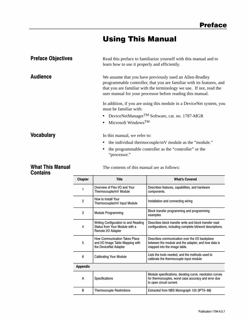
The contents of this manual are as follows:
Chapter Title What's Covered
1Overview of Flex I/O and YourThermocouple/mV Module
Describes features, capabilities, and hardwarecomponents.
2How to Install YourThermocouple/mV Input Module
Installation and connecting wiring
3 Module ProgrammingBlock transfer programming and programmingexamples
4Writing Configuration to and ReadingStatus from Your Module with aRemote I/O Adapter
Describes block transfer write and block transfer readconfigurations, including complete bit/word descriptions.
5How Communication Takes Placeand I/O Image Table Mapping withthe DeviceNet Adapter
Describes communication over the I/O backplanebetween the module and the adapter, and how data ismapped into the image table.
6 Calibrating Your ModuleLists the tools needed, and the methods used tocalibrate the thermocouple input module
Appendix
A SpecificationsModule specifications, derating curve, resolution curvesfor thermocouples, worst case accuracy and error dueto open circuit current.
B Thermocouple Restrictions Extracted from NBS Monograph 125 (IPTS-68)
Preface Objectives
Audience
Vocabulary
What This ManualContains
Using This ManualP–2
Publication 17946.5.7
We use these conventions in this manual:
In this manual, we show: Like this:
that there is more information about a topicin another chapter in this manual
that there is more information about thetopic in another manual
More
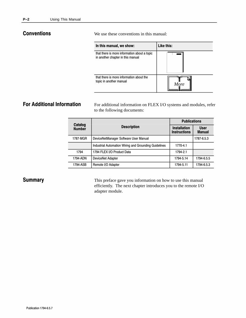
For additional information on FLEX I/O systems and modules, referto the following documents:
CatalogPublications
CatalogNumber
Description InstallationInstructions
UserManual
1787MGR DeviceNetManager Software User Manual 17876.5.3
Industrial Automation Wiring and Grounding Guidelines 17704.1
1794 1794 FLEX I/O Product Data 17942.1
1794ADN DeviceNet Adapter 17945.14 17946.5.5
1794ASB Remote I/O Adapter 17945.11 17946.5.3
This preface gave you information on how to use this manualefficiently. The next chapter introduces you to the remote I/Oadapter module.
Conventions
For Additional Information
Summary
Chapter 1
Publication 17946.5.7
Overview of FLEX I/O and yourThermocouple/mV Module
In this chapter, we tell you:
• what the FLEX I/O system is and what it contains
• how FLEX I/O modules communicate with programmablecontrollers
• the features of your thermocouple module
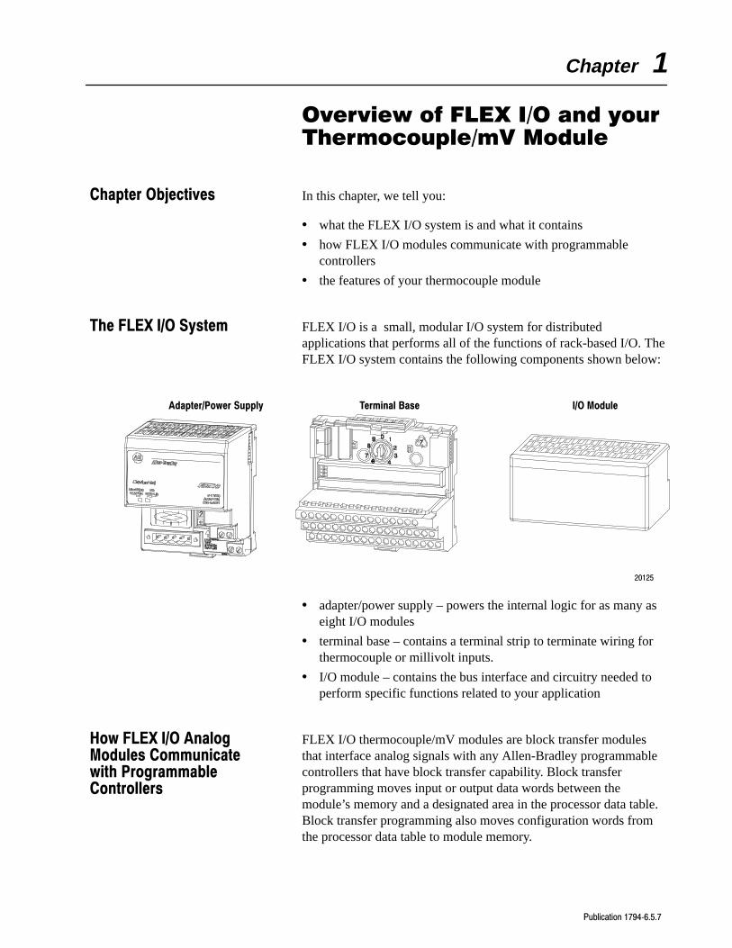
FLEX I/O is a small, modular I/O system for distributedapplications that performs all of the functions of rack-based I/O. TheFLEX I/O system contains the following components shown below:
Adapter/Power Supply Terminal Base I/O Module
20125
• adapter/power supply – powers the internal logic for as many aseight I/O modules
• terminal base – contains a terminal strip to terminate wiring forthermocouple or millivolt inputs.
• I/O module – contains the bus interface and circuitry needed toperform specific functions related to your application
FLEX I/O thermocouple/mV modules are block transfer modulesthat interface analog signals with any Allen-Bradley programmablecontrollers that have block transfer capability. Block transferprogramming moves input or output data words between themodule’s memory and a designated area in the processor data table.Block transfer programming also moves configuration words fromthe processor data table to module memory.
Chapter Objectives
The FLEX I/O System
How FLEX I/O AnalogModules Communicatewith ProgrammableControllers
Overview of FLEX I/O and your Thermocouple/mV Module 1-2
Publication 17946.5.7
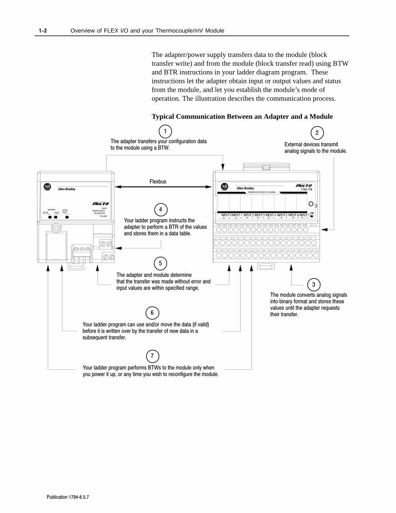
The adapter/power supply transfers data to the module (blocktransfer write) and from the module (block transfer read) using BTWand BTR instructions in your ladder diagram program. Theseinstructions let the adapter obtain input or output values and statusfrom the module, and let you establish the module’s mode ofoperation. The illustration describes the communication process.
Typical Communication Between an Adapter and a Module
ADAPTER
ACTIVE FAULT
LOCALFAULT
24VDC
POWER SUPPLY
RIO ADAPTER
1794ASB
AllenBradley
1
The adapter transfers your configuration datato the module using a BTW.
Flexbus
External devices transmitanalog signals to the module.
2
The module converts analog signalsinto binary format and stores thesevalues until the adapter requeststheir transfer.
3
Your ladder program instructs theadapter to perform a BTR of the valuesand stores them in a data table.
4
The adapter and module determinethat the transfer was made without error andinput values are within specified range.
5
Your ladder program can use and/or move the data (if valid)before it is written over by the transfer of new data in a subsequent transfer.
6
Your ladder program performs BTWs to the module only whenyou power it up, or any time you wish to reconfigure the module.
7
INPUT 0 INPUT 2 INPUT 4 INPUT 6INPUT 1 INPUT 3 INPUT 5 INPUT 7
THERMOCOUPLE INPUT 8 CHANNEL
3
1794-IT8AllenBradley
+ - + - + - + - + - + - + - + -
OK
Overview of FLEX I/O and your Thermocouple/mV Module 1-3
Publication 17946.5.7
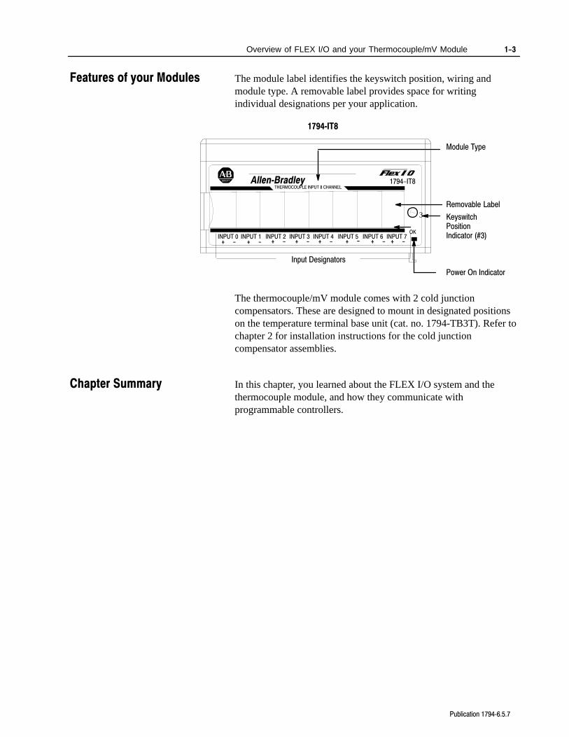
The module label identifies the keyswitch position, wiring andmodule type. A removable label provides space for writingindividual designations per your application.
Removable Label
Input Designators
KeyswitchPositionIndicator (#3)
1794IT8
Module Type
Power On Indicator
INPUT 0 INPUT 2 INPUT 4 INPUT 6INPUT 1 INPUT 3 INPUT 5 INPUT 7
THERMOCOUPLE INPUT 8 CHANNEL
3
1794-IT8AllenBradley
+ - + - + - + - + - + - + - + -
OK
The thermocouple/mV module comes with 2 cold junctioncompensators. These are designed to mount in designated positionson the temperature terminal base unit (cat. no. 1794-TB3T). Refer tochapter 2 for installation instructions for the cold junctioncompensator assemblies.
In this chapter, you learned about the FLEX I/O system and thethermocouple module, and how they communicate withprogrammable controllers.
Features of your Modules
Chapter Summary
Chapter 2
Publication 17946.5.7
How to Install YourThermocouple/mV InputModule
In this chapter, we tell you:
• how to install your module
• how to set the module keyswitch
• how to wire the terminal base
• about the indicators
Before installing your thermocouple/mV module in the I/O chassis:
You need to: As described under:
Calculate the power requirements of allmodules in each chassis.
Power Requirements, page 22
Position the keyswitch on the terminal base Installing the Module, page 2-4
!ATTENTION: The Thermocouple module does notreceive power from the backplane. +24V dc powermust be applied to your module before installation. Ifpower is not applied, the module position will appearto the adapter as an empty slot in your chassis.
If this product has the CE mark it is approved for installation withinthe European Union and EEA regions. It has been designed andtested to meet the following directives.
EMC Directive
This product is tested to meet Council Directive 89/336/EECElectromagnetic Compatibility (EMC) and the following standards,in whole or in part, documented in a technical construction file:
• EN 50081-2EMC – Generic Emission Standard, Part 2 –Industrial Environment
• EN 50082-2EMC – Generic Immunity Standard, Part 2 –Industrial Environment
This product is intended for use in an industrial environment.
Before You Install YourInput Module
European Union DirectiveCompliance
2–2 How to Install Your Thermocouple/mV Input Module
Publication 17946.5.7
Low Voltage Directive
This product is tested to meet Council Directive 73/23/EECLow Voltage, by applying the safety requirements of EN 61131–2Programmable Controllers, Part 2 – Equipment Requirements andTests.
For specific information required by EN 61131-2, see the appropriatesections in this publication, as well as the following Allen-Bradleypublications:
• Industrial Automation Wiring and Grounding Guidelines ForNoise Immunity, publication 1770-4.1
• Guidelines for Handling Lithium Batteries, publication AG-5.4
• Automation Systems Catalog, publication B111
The wiring of the terminal base unit is determined by the currentdraw through the terminal base. Make certain that the current drawdoes not exceed 10A.
!ATTENTION: Total current draw through theterminal base unit is limited to 10A. Separate powerconnections may be necessary.
!ATTENTION: Do not daisy chain power or groundfrom the thermocouple terminal base unit to any ac ordc discrete module terminal base unit.
Power Requirements
2–3How to Install Your Thermocouple/mV Input Module
Publication 17946.5.7
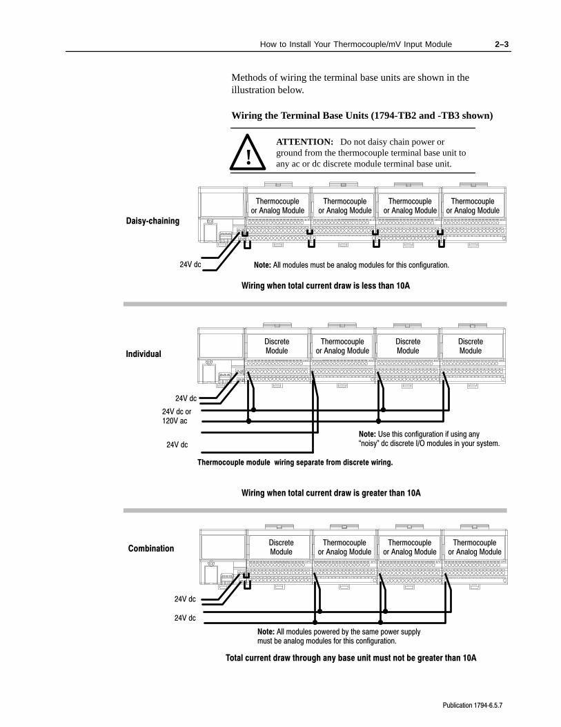
Methods of wiring the terminal base units are shown in theillustration below.
Wiring the Terminal Base Units (1794-TB2 and -TB3 shown)
Wiring when total current draw is less than 10A
Wiring when total current draw is greater than 10A
Daisychaining
Individual
Total current draw through any base unit must not be greater than 10A
Combination
24V dc
24V dc
24V dc
24V dc
24V dc or120V ac
24V dc
ATTENTION: Do not daisy chain power orground from the thermocouple terminal base unit toany ac or dc discrete module terminal base unit.!
Note: Use this configuration if using any noisy" dc discrete I/O modules in your system.
Thermocouple module wiring separate from discrete wiring.
Thermocoupleor Analog Module
Note: All modules powered by the same power supply must be analog modules for this configuration.
Note: All modules must be analog modules for this configuration.
Thermocoupleor Analog Module
Thermocoupleor Analog Module
Thermocoupleor Analog Module
Thermocoupleor Analog Module
DiscreteModule
DiscreteModule
Thermocoupleor Analog Module
Thermocoupleor Analog Module
Thermocoupleor Analog Module
DiscreteModule
DiscreteModule
2–4 How to Install Your Thermocouple/mV Input Module
Publication 17946.5.7
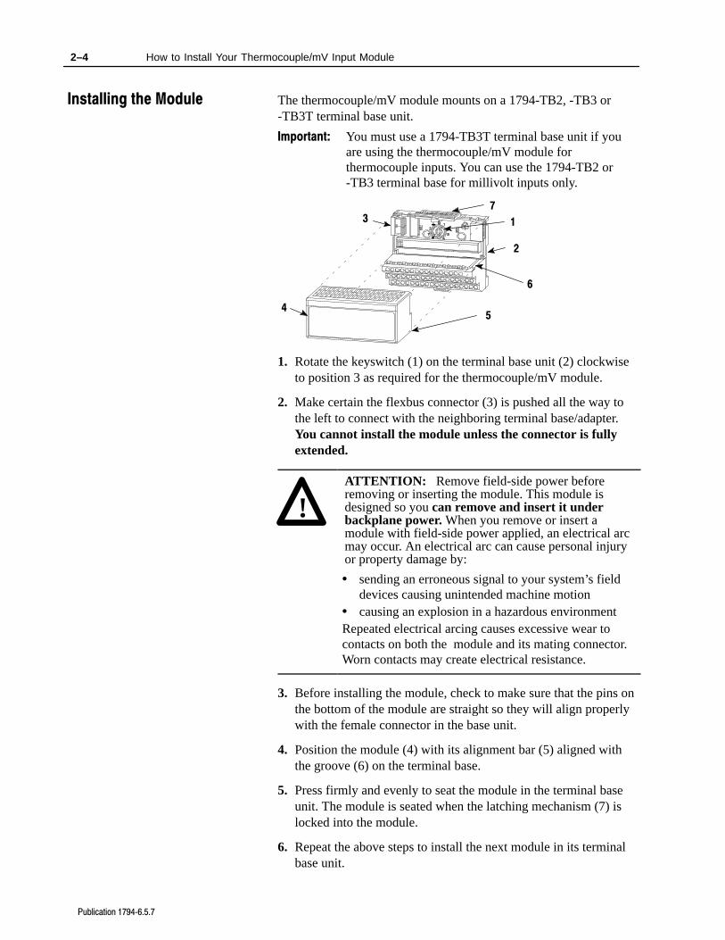
The thermocouple/mV module mounts on a 1794-TB2, -TB3 or-TB3T terminal base unit.
Important: You must use a 1794-TB3T terminal base unit if youare using the thermocouple/mV module forthermocouple inputs. You can use the 1794-TB2 or-TB3 terminal base for millivolt inputs only.
4
13
2
5
6
7
1. Rotate the keyswitch (1) on the terminal base unit (2) clockwiseto position 3 as required for the thermocouple/mV module.
2. Make certain the flexbus connector (3) is pushed all the way tothe left to connect with the neighboring terminal base/adapter.You cannot install the module unless the connector is fullyextended.
!ATTENTION: Remove field-side power beforeremoving or inserting the module. This module isdesigned so you can remove and insert it underbackplane power. When you remove or insert amodule with field-side power applied, an electrical arcmay occur. An electrical arc can cause personal injuryor property damage by:
• sending an erroneous signal to your system’s fielddevices causing unintended machine motion
• causing an explosion in a hazardous environmentRepeated electrical arcing causes excessive wear tocontacts on both the module and its mating connector.Worn contacts may create electrical resistance.
3. Before installing the module, check to make sure that the pins onthe bottom of the module are straight so they will align properlywith the female connector in the base unit.
4. Position the module (4) with its alignment bar (5) aligned withthe groove (6) on the terminal base.
5. Press firmly and evenly to seat the module in the terminal baseunit. The module is seated when the latching mechanism (7) islocked into the module.
6. Repeat the above steps to install the next module in its terminalbase unit.
Installing the Module
2–5How to Install Your Thermocouple/mV Input Module
Publication 17946.5.7
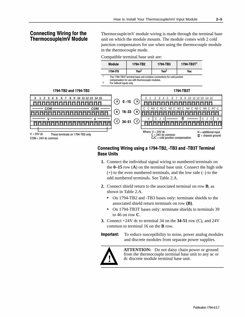
Thermocouple/mV module wiring is made through the terminal baseunit on which the module mounts. The module comes with 2 coldjunction compensators for use when using the thermocouple modulein the thermocouple mode.
Compatible terminal base unit are:
Module 1794TB2 1794TB3 1794TB3T1
1794IT8 Yes2 Yes2 Yes
1 The 1794TB3T terminal base unit contains connections for cold junctioncompensation for use with thermocouple modules.
2 For millivolt inputs only.
0 1 2 3 4 5 6 7 8 9 10 11 12 13 14 15A
B
C
0 1 2 3 4 5 6 7 8 9 10 11 12 13 14 15
C N0 C N1 C N2 C CN3 C N4 C N5 C N6 C N7
V C J C C J C V
C
A
B
C
Where: V = 24V dcC = 24V dc common
N = additional input
CJC = cold junction compensation= chassis ground
COM COM
V V
1794TB2 and 1794TB3 1794TB3T
These terminals on 1794TB3 only.V = 24V dc
0 -15
34-51
16-33
COM = 24V dc common
Connecting Wiring using a 1794TB2, TB3 and TB3T TerminalBase Units
1. Connect the individual signal wiring to numbered terminals onthe 0–15 row (A) on the terminal base unit. Connect the high side(+) to the even numbered terminals, and the low side (–) to theodd numbered terminals. See Table 2.A.
2. Connect shield return to the associated terminal on row B, asshown in Table 2.A.
• On 1794-TB2 and -TB3 bases only: terminate shields to theassociated shield return terminals on row (B).
• On 1794-TB3T bases only: terminate shields to terminals 39to 46 on row C.
3. Connect +24V dc to terminal 34 on the 34-51 row (C), and 24Vcommon to terminal 16 on the B row.
Important: To reduce susceptibility to noise, power analog modulesand discrete modules from separate power supplies.
!ATTENTION: Do not daisy chain power or groundfrom the thermocouple terminal base unit to any ac ordc discrete module terminal base unit.
Connecting Wiring for theThermocouple/mV Module
2–6 How to Install Your Thermocouple/mV Input Module
Publication 17946.5.7
!ATTENTION: The Thermocouple/mV module doesnot receive power from the backplane. +24V dc powermust be applied to your module before installation. Ifpower is not applied, the module position will appearto the adapter as an empty slot in your chassis.
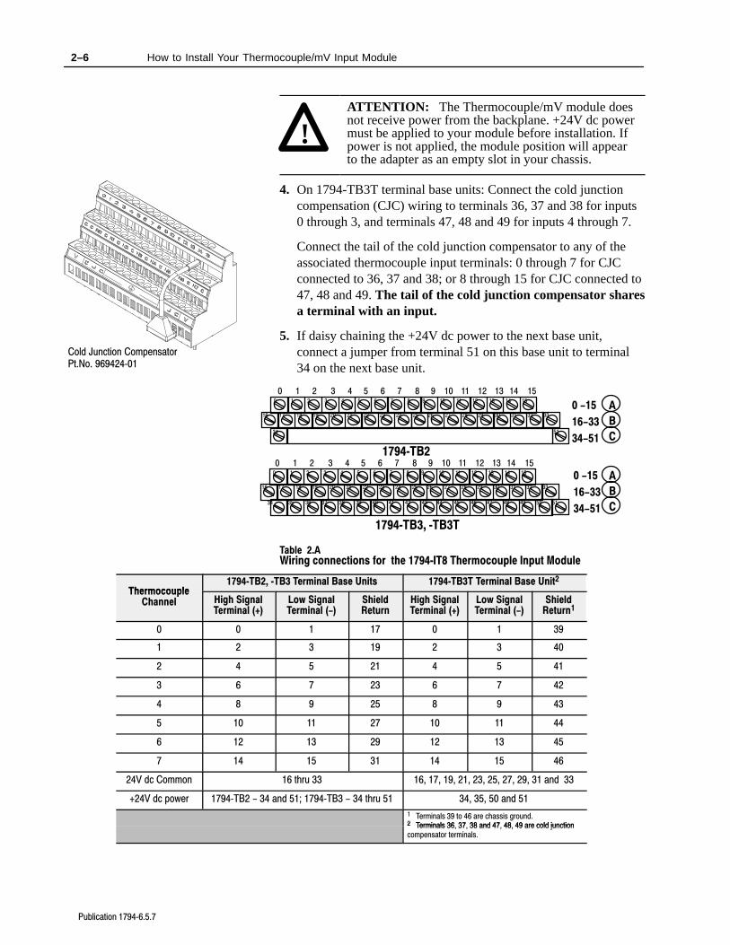
4. On 1794-TB3T terminal base units: Connect the cold junctioncompensation (CJC) wiring to terminals 36, 37 and 38 for inputs0 through 3, and terminals 47, 48 and 49 for inputs 4 through 7.
Connect the tail of the cold junction compensator to any of theassociated thermocouple input terminals: 0 through 7 for CJCconnected to 36, 37 and 38; or 8 through 15 for CJC connected to47, 48 and 49. The tail of the cold junction compensator sharesa terminal with an input.
5. If daisy chaining the +24V dc power to the next base unit,connect a jumper from terminal 51 on this base unit to terminal34 on the next base unit.
17 18 19 20 21 22 23 24 25 26 27 28 29 30 31 32 33
0 1 2 3 4 5 6 7 8 9 10 11 12 13 14 15
16
1 2 3 4 5 6 7 8 9 10 11 12 13 14 150
35 36 37 38 39 40 41 42 43 44 45 46 47 48 49 50 5134
1794TB3, TB3T
0 -15
34-51
16-33
A
B
C
1 5134
17 18 19 20 21 22 23 24 25 26 27 28 29 30 31 32 33
0 1 2 3 4 5 6 7 8 9 10 11 12 13 14 15
16
0 -15
34-51
16-33
1 2 3 4 5 6 7 8 9 10 11 12 13 14 150
1794TB2
A
B
C
Table 2.A Wiring connections for the 1794IT8 Thermocouple Input Module
Thermocouple1794TB2, TB3 Terminal Base Units 1794TB3T Terminal Base Unit2
ThermocoupleChannel High Signal
Terminal (+)Low SignalTerminal (-)
ShieldReturn
High SignalTerminal (+)
Low SignalTerminal (-)
ShieldReturn1
0 0 1 17 0 1 39
1 2 3 19 2 3 40
2 4 5 21 4 5 41
3 6 7 23 6 7 42
4 8 9 25 8 9 43
5 10 11 27 10 11 44
6 12 13 29 12 13 45
7 14 15 31 14 15 46
24V dc Common 16 thru 33 16, 17, 19, 21, 23, 25, 27, 29, 31 and 33
+24V dc power 1794TB2 - 34 and 51; 1794TB3 - 34 thru 51 34, 35, 50 and 51
1 Terminals 39 to 46 are chassis ground.2 Terminals 36 37 38 and 47 48 49 are cold junction2 Terminals 36, 37, 38 and 47, 48, 49 are cold junctioncompensator terminals.
Cold Junction CompensatorPt.No. 96942401
2–7How to Install Your Thermocouple/mV Input Module
Publication 17946.5.7
!ATTENTION: The thermocouple/mV modules donot receive power from the backplane. +24V dc powermust be applied to your module before operation. Ifpower is not applied, the module position will appearto the adapter as an empty slot in your chassis. If theadapter does not recognize your module afterinstallation is completed, cycle power to the adapter.
!ATTENTION: Total current draw through theterminal base unit is limited to 10A. Separate powerconnections to the terminal base unit may be necessary.
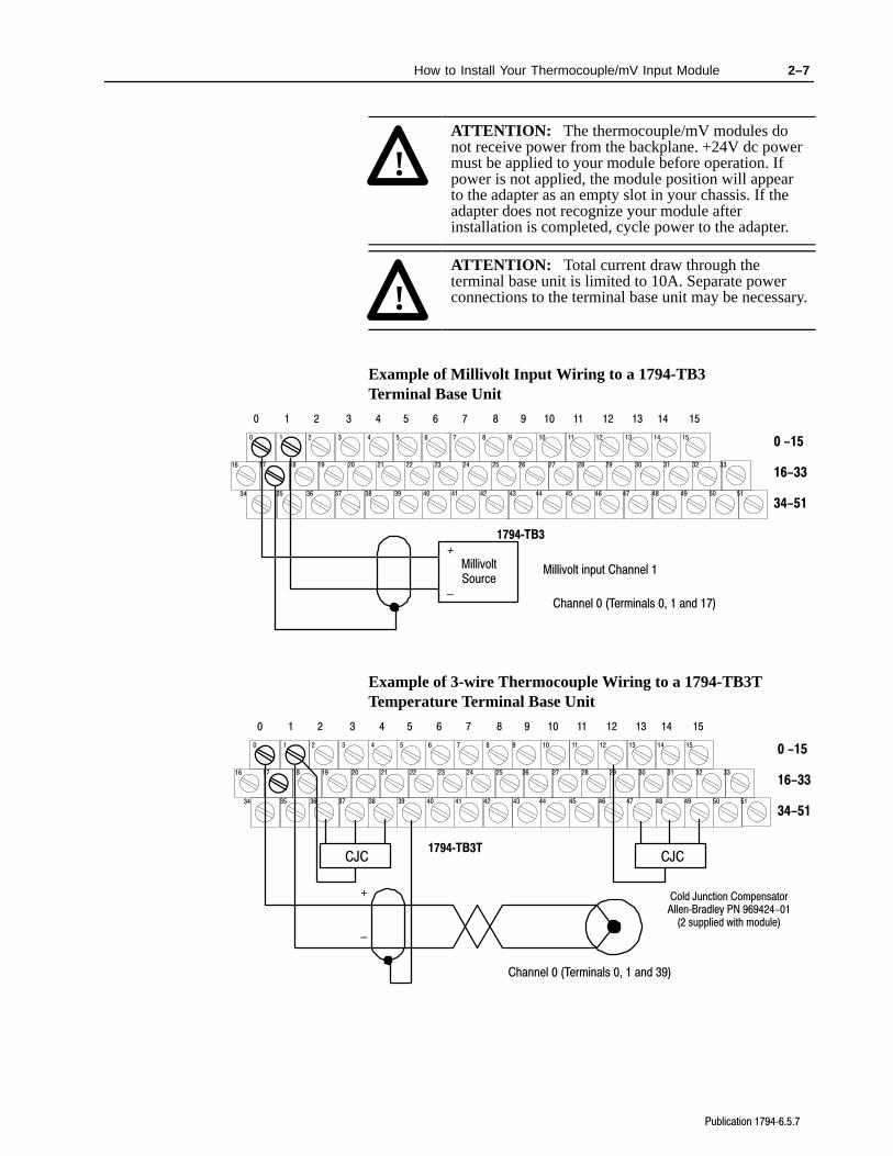
Example of Millivolt Input Wiring to a 1794-TB3Terminal Base Unit
17 18 19 20 21 22 23 24 25 26 27 28 29 30 31 32 33
0 1 2 3 4 5 6 7 8 9 10 11 12 13 14 15
16
1 2 3 4 5 6 7 8 9 10 11 12 13 14 150
35 36 37 38 39 40 41 42 43 44 45 46 47 48 49 50 5134
1794TB3
0 -15
34-51
16-33
+
–
Millivolt input Channel 1MillivoltSource
Channel 0 (Terminals 0, 1 and 17)
Example of 3-wire Thermocouple Wiring to a 1794-TB3T Temperature Terminal Base Unit
17 18 19 20 21 22 23 24 25 26 27 28 29 30 31 32 33
0 1 2 3 4 5 6 7 8 9 10 11 12 13 14 15
16
1 2 3 4 5 6 7 8 9 10 11 12 13 14 150
35 36 37 38 39 40 41 42 43 44 45 46 47 48 49 50 5134
1794TB3T
0 -15
34-51
16-33
+
–
Channel 0 (Terminals 0, 1 and 39)
CJC CJC
Cold Junction CompensatorAllenBradley PN 969424-01
(2 supplied with module)
2–8 How to Install Your Thermocouple/mV Input Module
Publication 17946.5.7
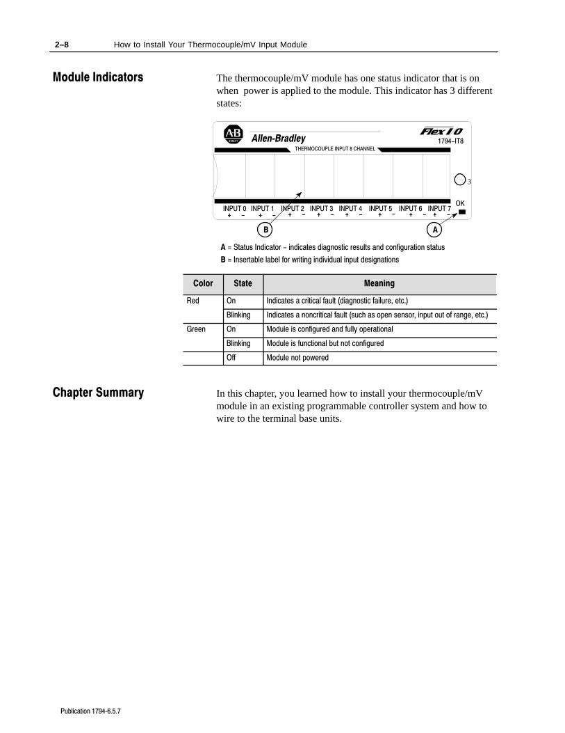
The thermocouple/mV module has one status indicator that is onwhen power is applied to the module. This indicator has 3 differentstates:
AB
A = Status Indicator - indicates diagnostic results and configuration status
B = Insertable label for writing individual input designations
INPUT 0 INPUT 2 INPUT 4 INPUT 6INPUT 1 INPUT 3 INPUT 5 INPUT 7
THERMOCOUPLE INPUT 8 CHANNEL
3
1794-IT8AllenBradley
+ - + - + - + - + - + - + - + -
OK
Color State Meaning
Red On Indicates a critical fault (diagnostic failure, etc.)
Blinking Indicates a noncritical fault (such as open sensor, input out of range, etc.)
Green On Module is configured and fully operational
Blinking Module is functional but not configured
Off Module not powered
In this chapter, you learned how to install your thermocouple/mVmodule in an existing programmable controller system and how towire to the terminal base units.
Module Indicators
Chapter Summary
Chapter 3
Publication 17946.5.7
Module Programming
In this chapter, we tell you about:
• block transfer programming
• sample programs for the PLC-3 and PLC-5 processors
Your thermocouple/mV module communicates with the processorthrough bidirectional block transfers. This is the sequential operationof both read and write block transfer instructions.
A configuration block transfer write (BTW) is initiated when thethermocouple module is first powered up, and subsequently onlywhen the programmer wants to enable or disable features of themodule. The configuration BTW sets the bits which enable theprogrammable features of the module, such as scaling, alarms,ranges, etc. Block transfer reads are performed to retrieveinformation from the module.
Block transfer read (BTR) programming moves status and data fromthe module to the processor’s data table. The processor user programinitiates the request to transfer data from the module to the processor.The transferred words contain module status, channel status andinput data from the module.
!ATTENTION: If the thermocouple/mV module isnot powered up before the remote I/O adapter, theadapter will not recognize the module. Make certainthat the thermocouple/mV module is installed andpowered before or simultaneously with the remote I/Oadapter. If the adapter does not establishcommunication with the module, cycle power to theadapter.
The following sample programs are minimum programs; all rungsand conditioning must be included in your application program. Youcan disable BTRs, or add interlocks to prevent writes if desired. Donot eliminate any storage bits or interlocks included in the sampleprograms. If interlocks are removed, the program may not workproperly.
Your program should monitor status bits and block transfer readactivity.
Chapter Objectives
Block TransferProgramming
3–2 Module Programming
Publication 17946.5.7
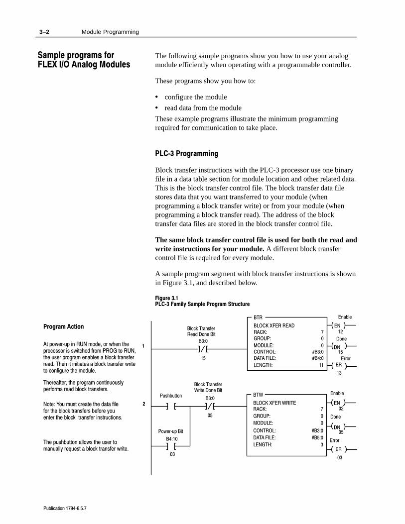
The following sample programs show you how to use your analogmodule efficiently when operating with a programmable controller.
These programs show you how to:
• configure the module
• read data from the module
These example programs illustrate the minimum programmingrequired for communication to take place.
PLC3 Programming
Block transfer instructions with the PLC-3 processor use one binaryfile in a data table section for module location and other related data.This is the block transfer control file. The block transfer data filestores data that you want transferred to your module (whenprogramming a block transfer write) or from your module (whenprogramming a block transfer read). The address of the blocktransfer data files are stored in the block transfer control file.
The same block transfer control file is used for both the read andwrite instructions for your module. A different block transfercontrol file is required for every module.
A sample program segment with block transfer instructions is shownin Figure 3.1, and described below.
Figure 3.1 PLC3 Family Sample Program Structure
EN
BTR
BLOCK XFER READ
RACK:
GROUP:
MODULE:
CONTROL:
7
0
0
#B3:0
DATA FILE:
LENGTH:
#B4:0
11
EN
BTW
BLOCK XFER WRITERACK:
GROUP:
MODULE:
CONTROL:
7
0
0
#B3:0DN
DATA FILE:
LENGTH:
#B5:0
3
B3:0
05
Block TransferRead Done Bit
ER
Enable
Done
Error
12
15
13
Enable
Done
Error
02
05
03
Block TransferWrite Done Bit
1
2
DN
ER
B3:0
15
Program Action
At powerup in RUN mode, or when theprocessor is switched from PROG to RUN,the user program enables a block transferread. Then it initiates a block transfer writeto configure the module.
Thereafter, the program continuouslyperforms read block transfers.
Note: You must create the data filefor the block transfers before youenter the block transfer instructions.
The pushbutton allows the user tomanually request a block transfer write.
B4:10
03
Powerup Bit
Pushbutton
Sample programs forFLEX I/O Analog Modules
3–3Module Programming
Publication 17946.5.7
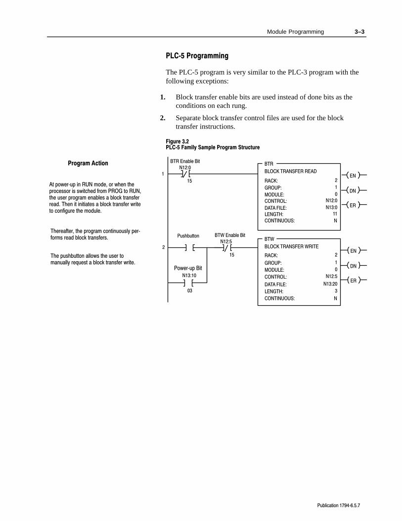
PLC5 Programming
The PLC-5 program is very similar to the PLC-3 program with thefollowing exceptions:
1. Block transfer enable bits are used instead of done bits as theconditions on each rung.
2. Separate block transfer control files are used for the blocktransfer instructions.
Figure 3.2 PLC5 Family Sample Program Structure
BTR Enable Bit
EN
DN
BTW Enable Bit
1
2
ER
EN
DN
ER
BTR
BLOCK TRANSFER READ
RACK:
GROUP:
MODULE:
DATA FILE:
LENGTH:
CONTINUOUS: N
BTW
BLOCK TRANSFER WRITE
RACK:
GROUP:
MODULE:
LENGTH:
CONTINUOUS: N
2
1
0
N13:0
11
2
1
0
3
Program Action
CONTROL: N12:0
DATA FILE: N13:20
CONTROL: N12:5
N12:5
15
N12:0
15
Thereafter, the program continuously performs read block transfers. Pushbutton
The pushbutton allows the user tomanually request a block transfer write.
N13:10
03
Powerup Bit
At powerup in RUN mode, or when theprocessor is switched from PROG to RUN,the user program enables a block transferread. Then it initiates a block transfer writeto configure the module.

3–4 Module Programming
Publication 17946.5.7
PLC2 Programming
The 1794 analog I/O modules are not recommended for use withPLC-2 family programmable controllers due to the number of digitsneeded for high resolution.
In this chapter, you learned how to program your programmablecontroller. You were given sample programs for your PLC-3 andPLC-5 family processors.
Chapter Summary
Chapter 4
Publication 17946.5.7
Writing Configuration to andReading Status from yourModule with a Remote I/OAdapter
In this chapter, we tell you about:
• configuring your module’s features
• entering your data
• reading data from your module
• the read block format
Because of the wide variety of possible configurations, you mustconfigure your module to conform to the specific application thatyou have chosen. The module is configured using a group of datatable words that are transferred to the module using a block transferwrite instruction.
The software configurable features available for the thermocouplemodule are:
• input/output range selection, including full range and bipolar
• selectable first notch filter
• data reported in oF, oC, unipolar or bipolar count
Note: PLC-5 family programmable controllers that use 6200software (version 5.2 or later) programming tools can take advantageof the IOCONFIG utility to configure these modules. IOCONFIGuses menu-based screens for configuration without having to setindividual bits in particular locations. Refer to your 6200 softwareliterature for details.
Chapter Objectives
Configuring YourThermocouple/mV Module
4–2 Writing Configuration to and Reading Status from your Module with a Remote I/O Adapter
Publication 17946.5.7
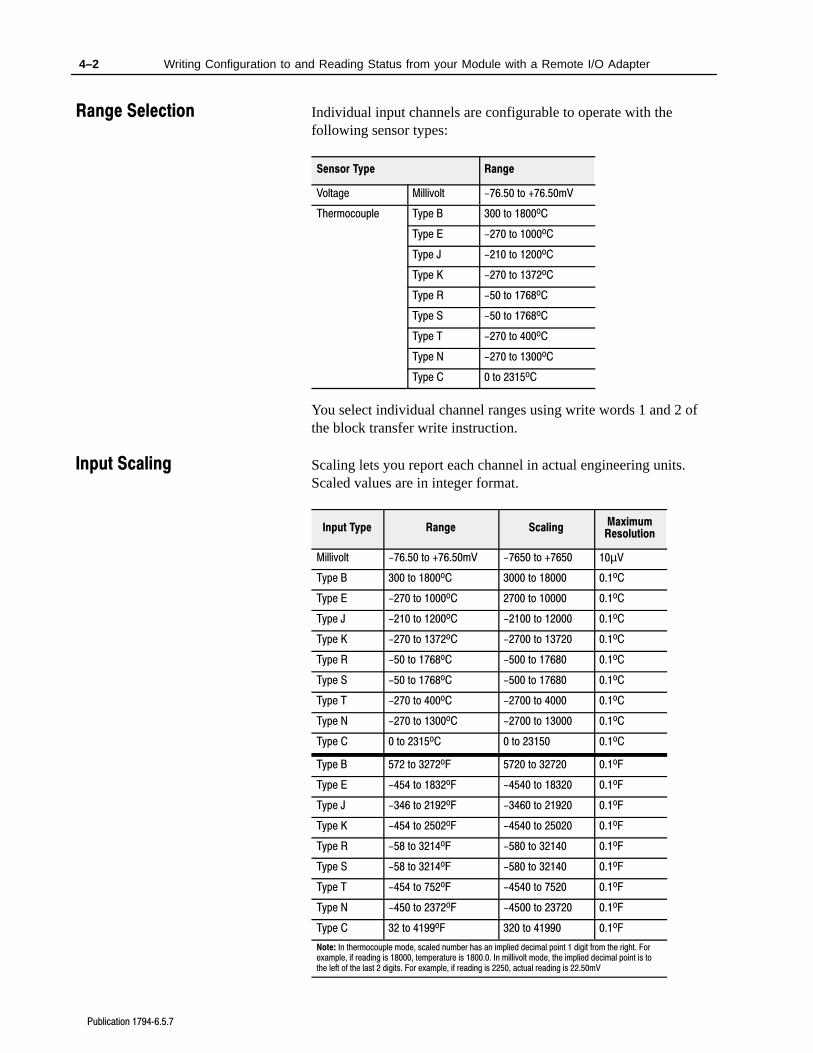
Individual input channels are configurable to operate with thefollowing sensor types:
Sensor Type Range
Voltage Millivolt -76.50 to +76.50mV
Thermocouple Type B 300 to 1800oC
Type E -270 to 1000oC
Type J -210 to 1200oC
Type K -270 to 1372oC
Type R -50 to 1768oC
Type S -50 to 1768oC
Type T -270 to 400oC
Type N -270 to 1300oC
Type C 0 to 2315oC
You select individual channel ranges using write words 1 and 2 ofthe block transfer write instruction.
Scaling lets you report each channel in actual engineering units.Scaled values are in integer format.
Input Type Range ScalingMaximumResolution
Millivolt -76.50 to +76.50mV -7650 to +7650 10µV
Type B 300 to 1800oC 3000 to 18000 0.1oC
Type E -270 to 1000oC 2700 to 10000 0.1oC
Type J -210 to 1200oC -2100 to 12000 0.1oC
Type K -270 to 1372oC -2700 to 13720 0.1oC
Type R -50 to 1768oC -500 to 17680 0.1oC
Type S -50 to 1768oC -500 to 17680 0.1oC
Type T -270 to 400oC -2700 to 4000 0.1oC
Type N -270 to 1300oC -2700 to 13000 0.1oC
Type C 0 to 2315oC 0 to 23150 0.1oC
Type B 572 to 3272oF 5720 to 32720 0.1oF
Type E -454 to 1832oF -4540 to 18320 0.1oF
Type J -346 to 2192oF -3460 to 21920 0.1oF
Type K -454 to 2502oF -4540 to 25020 0.1oF
Type R -58 to 3214oF -580 to 32140 0.1oF
Type S -58 to 3214oF -580 to 32140 0.1oF
Type T -454 to 752oF -4540 to 7520 0.1oF
Type N -450 to 2372oF -4500 to 23720 0.1oF
Type C 32 to 4199oF 320 to 41990 0.1oF
Note: In thermocouple mode, scaled number has an implied decimal point 1 digit from the right. Forexample, if reading is 18000, temperature is 1800.0. In millivolt mode, the implied decimal point is tothe left of the last 2 digits. For example, if reading is 2250, actual reading is 22.50mV
Range Selection
Input Scaling
4–3Writing Configuration to and Reading Status from your Module with a Remote I/O Adapter
Publication 17946.5.7
You select input scaling using the designated words of the writeblock transfer instruction. Refer to the Bit/Word description for writeword 0, bits 00 and 01.
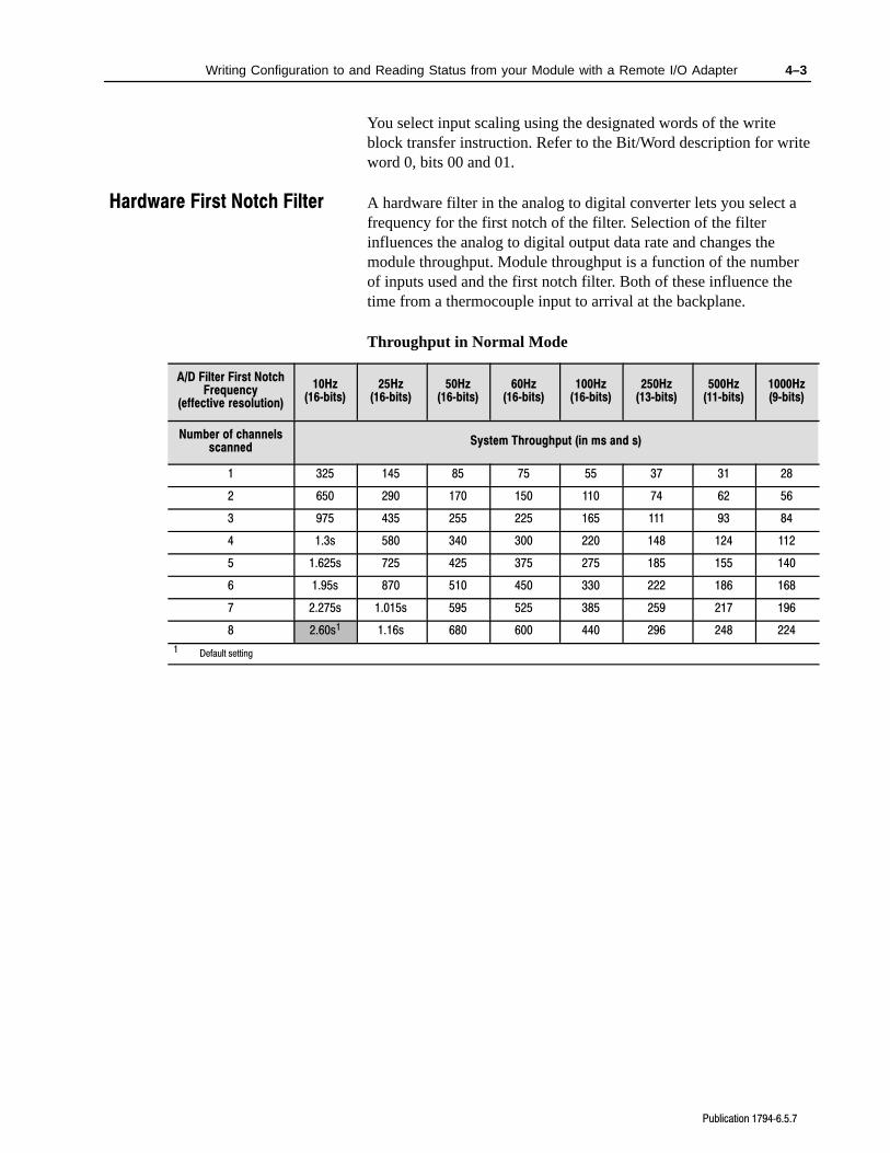
A hardware filter in the analog to digital converter lets you select afrequency for the first notch of the filter. Selection of the filterinfluences the analog to digital output data rate and changes themodule throughput. Module throughput is a function of the numberof inputs used and the first notch filter. Both of these influence thetime from a thermocouple input to arrival at the backplane.
Throughput in Normal Mode
A/D Filter First NotchFrequency
(effective resolution)
10Hz(16bits)
25Hz(16bits)
50Hz(16bits)
60Hz(16bits)
100Hz(16bits)
250Hz(13bits)
500Hz(11bits)
1000Hz(9bits)
Number of channelsscanned
System Throughput (in ms and s)
1 325 145 85 75 55 37 31 28
2 650 290 170 150 110 74 62 56
3 975 435 255 225 165 111 93 84
4 1.3s 580 340 300 220 148 124 112
5 1.625s 725 425 375 275 185 155 140
6 1.95s 870 510 450 330 222 186 168
7 2.275s 1.015s 595 525 385 259 217 196
8 2.60s1 1.16s 680 600 440 296 248 224
1 Default setting
Hardware First Notch Filter
4–4 Writing Configuration to and Reading Status from your Module with a Remote I/O Adapter
Publication 17946.5.7
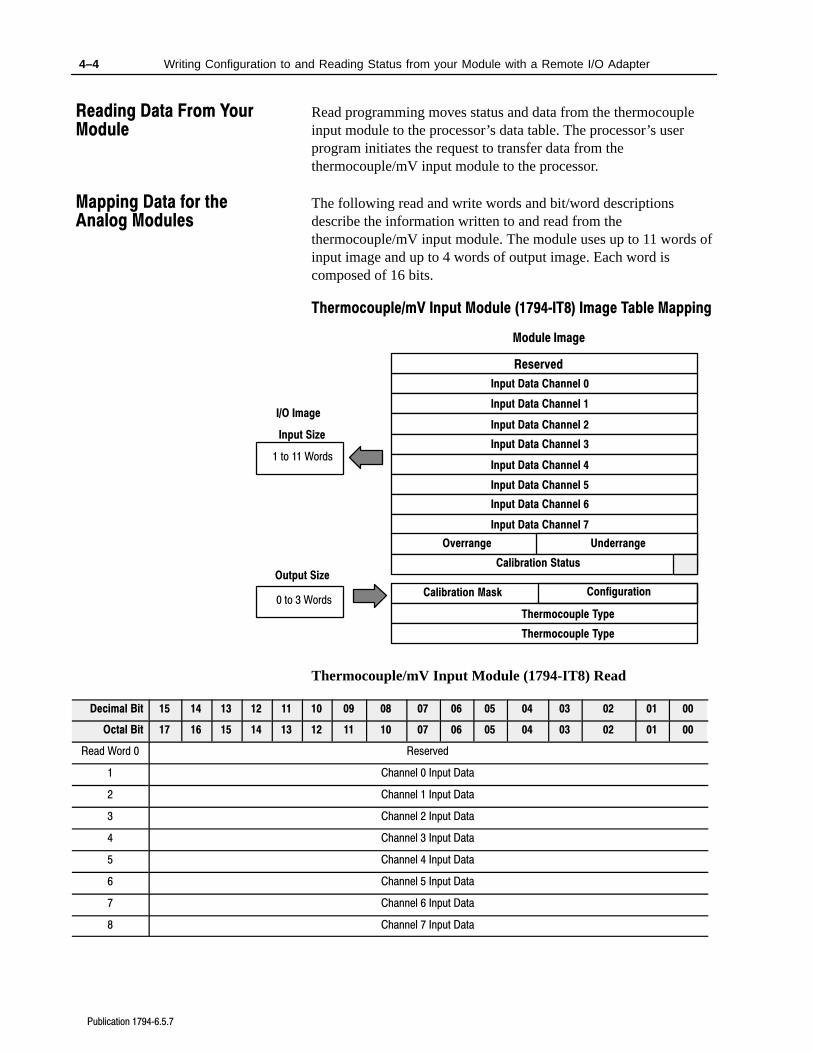
Read programming moves status and data from the thermocoupleinput module to the processor’s data table. The processor’s userprogram initiates the request to transfer data from thethermocouple/mV input module to the processor.
The following read and write words and bit/word descriptionsdescribe the information written to and read from thethermocouple/mV input module. The module uses up to 11 words ofinput image and up to 4 words of output image. Each word iscomposed of 16 bits.
Thermocouple/mV Input Module (1794IT8) Image Table Mapping
Module Image
I/O Image
Input Data Channel 0
Input Data Channel 1
Input Data Channel 2
Input Data Channel 3
Input Data Channel 4
Input Data Channel 5
Input Data Channel 6
Input Data Channel 7
Underrange
Calibration Mask
Thermocouple Type
Input Size
Output Size
0 to 3 Words
1 to 11 Words
Reserved
Overrange
Calibration Status
Thermocouple Type
Configuration
Thermocouple/mV Input Module (1794-IT8) Read
Decimal Bit 15 14 13 12 11 10 09 08 07 06 05 04 03 02 01 00
Octal Bit 17 16 15 14 13 12 11 10 07 06 05 04 03 02 01 00
Read Word 0 Reserved
1 Channel 0 Input Data
2 Channel 1 Input Data
3 Channel 2 Input Data
4 Channel 3 Input Data
5 Channel 4 Input Data
6 Channel 5 Input Data
7 Channel 6 Input Data
8 Channel 7 Input Data
Reading Data From YourModule
Mapping Data for theAnalog Modules
4–5Writing Configuration to and Reading Status from your Module with a Remote I/O Adapter
Publication 17946.5.7
00010203040506070809101112131415Decimal Bit
00010203040506071011121314151617Octal Bit
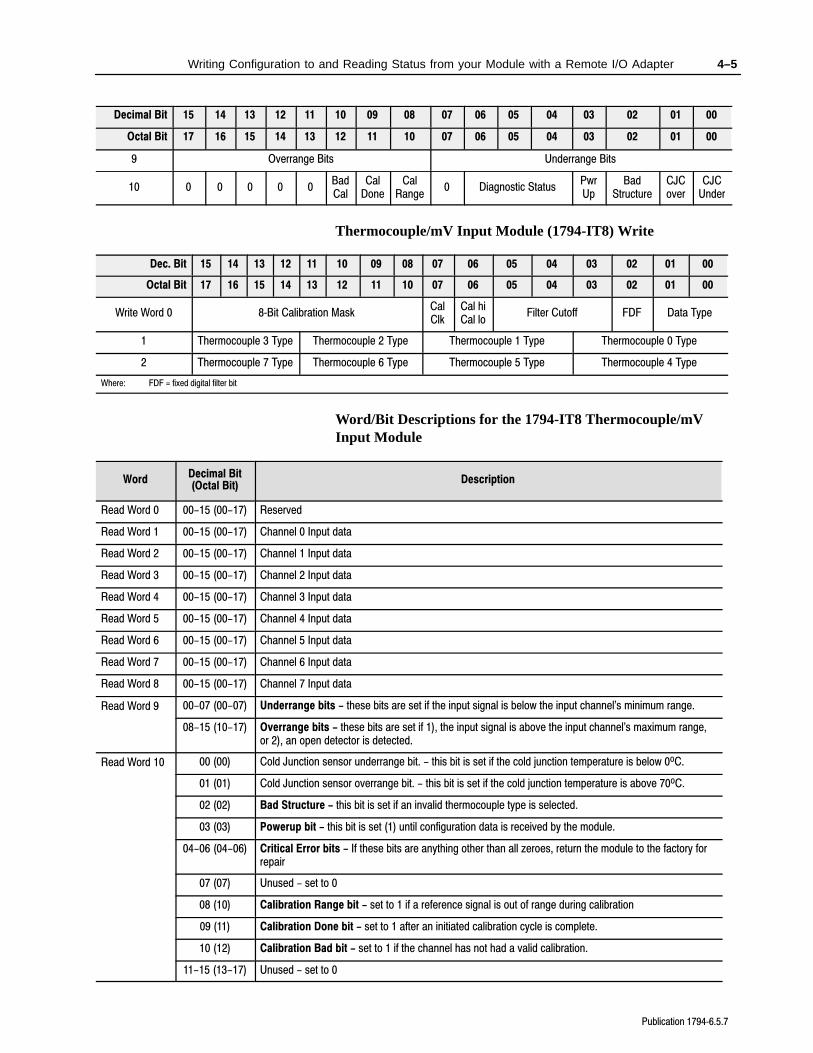
9 Overrange Bits Underrange Bits
10 0 0 0 0 0BadCal
CalDone
CalRange
0 Diagnostic StatusPwrUp
BadStructure
CJCover
CJCUnder
Thermocouple/mV Input Module (1794-IT8) Write
Dec. Bit 15 14 13 12 11 10 09 08 07 06 05 04 03 02 01 00
Octal Bit 17 16 15 14 13 12 11 10 07 06 05 04 03 02 01 00
Write Word 0 8Bit Calibration MaskCalClk
Cal hiCal lo
Filter Cutoff FDF Data Type
1 Thermocouple 3 Type Thermocouple 2 Type Thermocouple 1 Type Thermocouple 0 Type
2 Thermocouple 7 Type Thermocouple 6 Type Thermocouple 5 Type Thermocouple 4 Type
Where: FDF = fixed digital filter bit
Word/Bit Descriptions for the 1794-IT8 Thermocouple/mVInput Module
WordDecimal Bit(Octal Bit)
Description
Read Word 0 00-15 (00-17) Reserved
Read Word 1 00-15 (00-17) Channel 0 Input data
Read Word 2 00-15 (00-17) Channel 1 Input data
Read Word 3 00-15 (00-17) Channel 2 Input data
Read Word 4 00-15 (00-17) Channel 3 Input data
Read Word 5 00-15 (00-17) Channel 4 Input data
Read Word 6 00-15 (00-17) Channel 5 Input data
Read Word 7 00-15 (00-17) Channel 6 Input data
Read Word 8 00-15 (00-17) Channel 7 Input data
Read Word 9 00-07 (00-07) Underrange bits - these bits are set if the input signal is below the input channel's minimum range.
08-15 (10-17) Overrange bits - these bits are set if 1), the input signal is above the input channel's maximum range,or 2), an open detector is detected.
Read Word 10 00 (00) Cold Junction sensor underrange bit. - this bit is set if the cold junction temperature is below 0oC.
01 (01) Cold Junction sensor overrange bit. - this bit is set if the cold junction temperature is above 70oC.
02 (02) Bad Structure - this bit is set if an invalid thermocouple type is selected.
03 (03) Powerup bit - this bit is set (1) until configuration data is received by the module.
04-06 (04-06) Critical Error bits - If these bits are anything other than all zeroes, return the module to the factory forrepair
07 (07) Unused - set to 0
08 (10) Calibration Range bit - set to 1 if a reference signal is out of range during calibration
09 (11) Calibration Done bit - set to 1 after an initiated calibration cycle is complete.
10 (12) Calibration Bad bit - set to 1 if the channel has not had a valid calibration.
11-15 (13-17) Unused - set to 0
4–6 Writing Configuration to and Reading Status from your Module with a Remote I/O Adapter
Publication 17946.5.7
DescriptionDecimal Bit(Octal Bit)Word
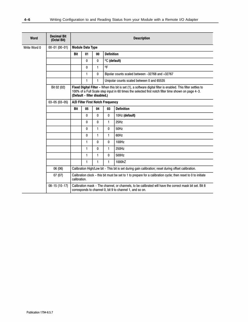
Write Word 0 00-01 (00-01) Module Data Type
Bit 01 00 Definition
0 0 oC (default)
0 1 oF
1 0 Bipolar counts scaled between -32768 and +32767
1 1 Unipolar counts scaled between 0 and 65535
Bit 02 (02) Fixed Digital Filter - When this bit is set (1), a software digital filter is enabled. This filter settles to100% of a Full Scale step input in 60 times the selected first notch filter time shown on page 4-3.(Default - filter disabled.)
03-05 (03-05) A/D Filter First Notch Frequency
Bit 05 04 03 Definition
0 0 0 10Hz (default)
0 0 1 25Hz
0 1 0 50Hz
0 1 1 60Hz
1 0 0 100Hz
1 0 1 250Hz
1 1 0 500Hz
1 1 1 1000hZ
06 (06) Calibration High/Low bit - This bit is set during gain calibration; reset during offset calibration.
07 (07) Calibration clock - this bit must be set to 1 to prepare for a calibration cycle; then reset to 0 to initiatecalibration.
08-15 (10-17) Calibration mask - The channel, or channels, to be calibrated will have the correct mask bit set. Bit 8corresponds to channel 0, bit 9 to channel 1, and so on.
4–7Writing Configuration to and Reading Status from your Module with a Remote I/O Adapter
Publication 17946.5.7
DescriptionDecimal Bit(Octal Bit)Word
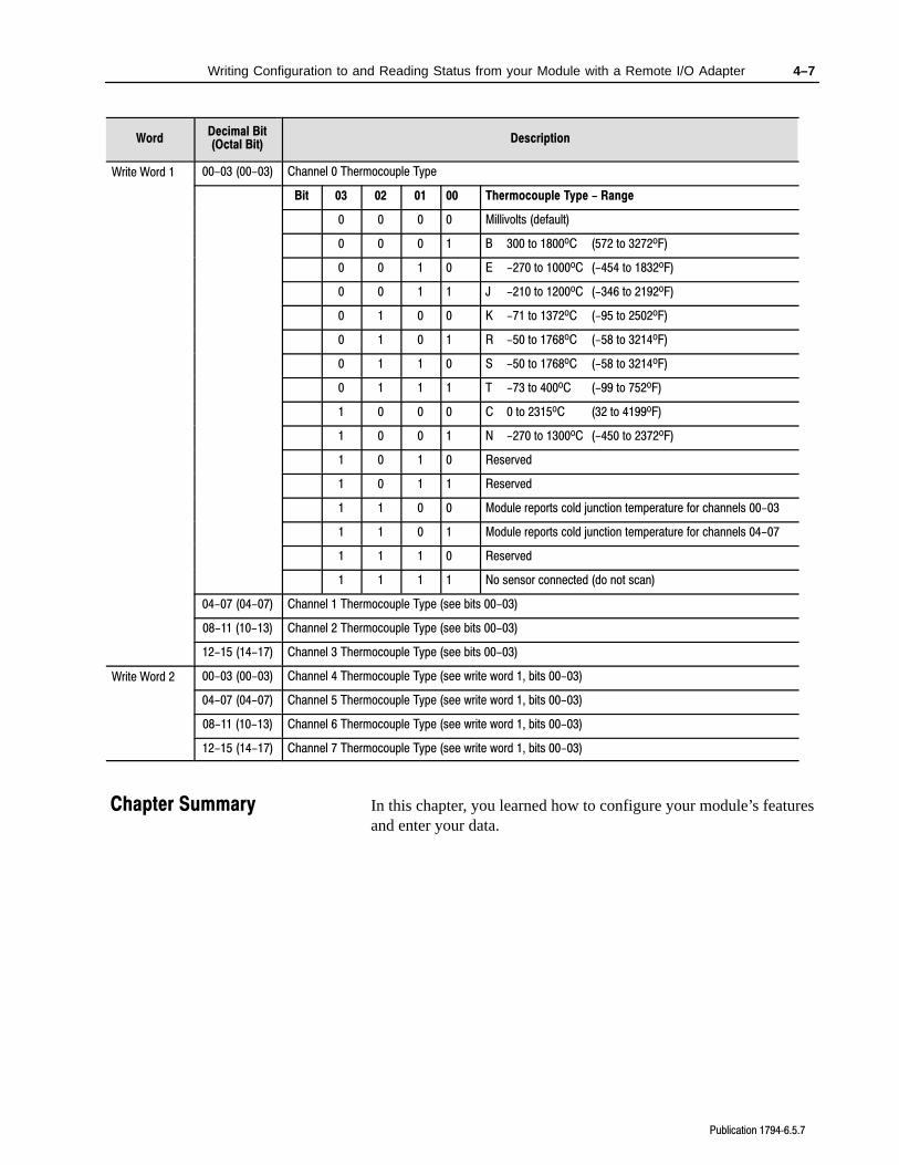
Write Word 1 00-03 (00-03) Channel 0 Thermocouple Type
Bit 03 02 01 00 Thermocouple Type - Range
0 0 0 0 Millivolts (default)
0 0 0 1 B 300 to 1800oC (572 to 3272oF)
0 0 1 0 E -270 to 1000oC (-454 to 1832oF)
0 0 1 1 J -210 to 1200oC (-346 to 2192oF)
0 1 0 0 K -71 to 1372oC (-95 to 2502oF)
0 1 0 1 R -50 to 1768oC (-58 to 3214oF)
0 1 1 0 S -50 to 1768oC (-58 to 3214oF)
0 1 1 1 T -73 to 400oC (-99 to 752oF)
1 0 0 0 C 0 to 2315oC (32 to 4199oF)
1 0 0 1 N -270 to 1300oC (-450 to 2372oF)
1 0 1 0 Reserved
1 0 1 1 Reserved
1 1 0 0 Module reports cold junction temperature for channels 00-03
1 1 0 1 Module reports cold junction temperature for channels 04-07
1 1 1 0 Reserved
1 1 1 1 No sensor connected (do not scan)
04-07 (04-07) Channel 1 Thermocouple Type (see bits 00-03)
08-11 (10-13) Channel 2 Thermocouple Type (see bits 00-03)
12-15 (14-17) Channel 3 Thermocouple Type (see bits 00-03)
Write Word 2 00-03 (00-03) Channel 4 Thermocouple Type (see write word 1, bits 00-03)
04-07 (04-07) Channel 5 Thermocouple Type (see write word 1, bits 00-03)
08-11 (10-13) Channel 6 Thermocouple Type (see write word 1, bits 00-03)
12-15 (14-17) Channel 7 Thermocouple Type (see write word 1, bits 00-03)
In this chapter, you learned how to configure your module’s featuresand enter your data.
Chapter Summary
Chapter 5
Publication 17946.5.7
How Communication TakesPlace and I/O Image TableMapping with the DeviceNetAdapter
In this chapter, we tell you about:
• DeviceNetManager software
• I/O structure
• image table mapping
• factory defaults
DeviceNetManager software is a software tool used to configureyour Flex I/O DeviceNet adapter and its related modules. Thissoftware tool can be connected to the adapter via the DeviceNetnetwork.
You must know and understand how DeviceNet Manager works inorder to add a device to the network. Refer to the DeviceNetManagerSoftware User Manual, publication 1787-6.5.3, and the DeviceNetAdapter Module User Manual, publication 1794-6.5.5.
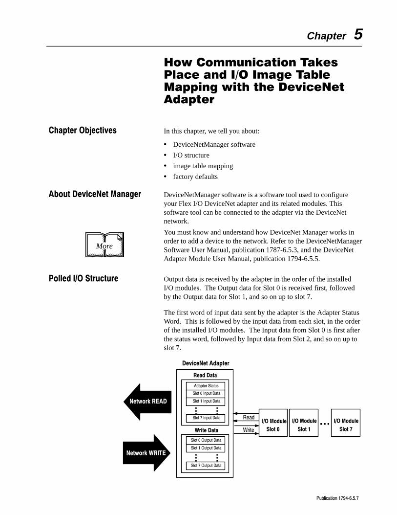
Output data is received by the adapter in the order of the installedI/O modules. The Output data for Slot 0 is received first, followedby the Output data for Slot 1, and so on up to slot 7.
The first word of input data sent by the adapter is the Adapter StatusWord. This is followed by the input data from each slot, in the orderof the installed I/O modules. The Input data from Slot 0 is first afterthe status word, followed by Input data from Slot 2, and so on up toslot 7.
Adapter Status
Slot 0 Input Data
Slot 1 Input Data
Slot 7 Input Data
Slot 0 Output Data
Slot 1 Output Data
Slot 7 Output Data
Read Data
Write Data
Network READ
Network WRITE
DeviceNet Adapter
Slot 0
I/O ModuleRead
Write Slot 1
I/O Module
Slot 7
I/O Module...
... ...
... ...
More
Chapter Objectives
About DeviceNet Manager
Polled I/O Structure
5–2 How Communication Takes Place and I/O Image Table Mapping with the DeviceNet Adapter
Publication 17946.5.7
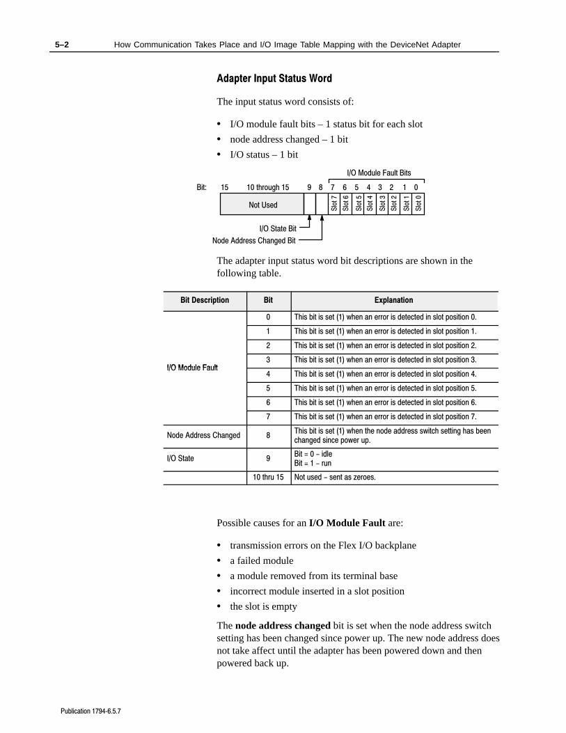
Adapter Input Status Word
The input status word consists of:
• I/O module fault bits – 1 status bit for each slot
• node address changed – 1 bit
• I/O status – 1 bit
15Bit: 01234567810 through 15
I/O Module Fault Bits
Node Address Changed Bit
Slo
t 0
Slo
t 1
Slo
t 2
Slo
t 3
Slo
t 4
Slo
t 5
Slo
t 6
Slo
t 7
9
I/O State Bit
Not Used
The adapter input status word bit descriptions are shown in thefollowing table.
Bit Description Bit Explanation
0 This bit is set (1) when an error is detected in slot position 0.
1 This bit is set (1) when an error is detected in slot position 1.
2 This bit is set (1) when an error is detected in slot position 2.
I/O Module Fault3 This bit is set (1) when an error is detected in slot position 3.
I/O Module Fault4 This bit is set (1) when an error is detected in slot position 4.
5 This bit is set (1) when an error is detected in slot position 5.
6 This bit is set (1) when an error is detected in slot position 6.
7 This bit is set (1) when an error is detected in slot position 7.
Node Address Changed 8This bit is set (1) when the node address switch setting has beenchanged since power up.
I/O State 9Bit = 0 - idleBit = 1 - run
10 thru 15 Not used - sent as zeroes.
Possible causes for an I/O Module Fault are:
• transmission errors on the Flex I/O backplane
• a failed module
• a module removed from its terminal base
• incorrect module inserted in a slot position
• the slot is empty
The node address changed bit is set when the node address switchsetting has been changed since power up. The new node address doesnot take affect until the adapter has been powered down and thenpowered back up.
5–3How Communication Takes Place and I/O Image Table Mapping with the DeviceNet Adapter
Publication 17946.5.7
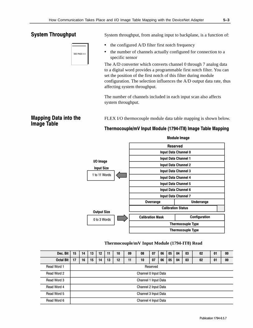
System throughput, from analog input to backplane, is a function of:
• the configured A/D filter first notch frequency
• the number of channels actually configured for connection to aspecific sensor
The A/D converter which converts channel 0 through 7 analog datato a digital word provides a programmable first notch filter. You canset the position of the first notch of this filter during moduleconfiguration. The selection influences the A/D output data rate, thusaffecting system throughput.
The number of channels included in each input scan also affectssystem throughput.
FLEX I/O thermocouple module data table mapping is shown below.
Thermocouple/mV Input Module (1794IT8) Image Table Mapping
Module Image
I/O Image
Input Data Channel 0
Input Data Channel 1
Input Data Channel 2
Input Data Channel 3
Input Data Channel 4
Input Data Channel 5
Input Data Channel 6
Input Data Channel 7
Underrange
Calibration Mask
Thermocouple Type
Input Size
Output Size
0 to 3 Words
1 to 11 Words
Reserved
Overrange
Calibration Status
Thermocouple Type
Configuration
Thermocouple/mV Input Module (1794-IT8) Read
Dec. Bit 15 14 13 12 11 10 09 08 07 06 05 04 03 02 01 00
Octal Bit 17 16 15 14 13 12 11 10 07 06 05 04 03 02 01 00
Read Word 1 Reserved
Read Word 2 Channel 0 Input Data
Read Word 3 Channel 1 Input Data
Read Word 4 Channel 2 Input Data
Read Word 5 Channel 3 Input Data
Read Word 6 Channel 4 Input Data
SEE PAGE 4-3
System Throughput
Mapping Data into the Image Table
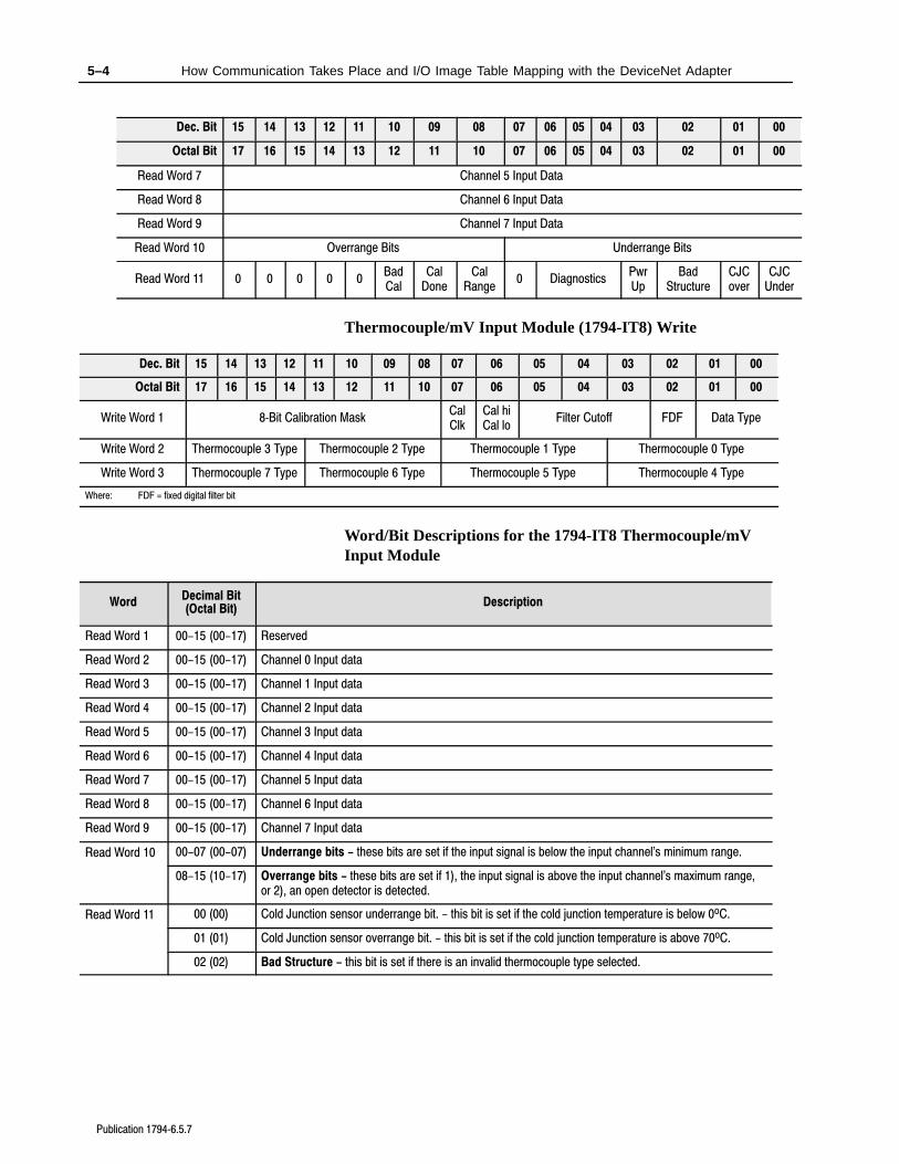
5–4 How Communication Takes Place and I/O Image Table Mapping with the DeviceNet Adapter
Publication 17946.5.7
00010203040506070809101112131415Dec. Bit
00010203040506071011121314151617Octal Bit
Read Word 7 Channel 5 Input Data
Read Word 8 Channel 6 Input Data
Read Word 9 Channel 7 Input Data
Read Word 10 Overrange Bits Underrange Bits
Read Word 11 0 0 0 0 0BadCal
CalDone
CalRange
0 DiagnosticsPwrUp
BadStructure
CJCover
CJCUnder
Thermocouple/mV Input Module (1794-IT8) Write
Dec. Bit 15 14 13 12 11 10 09 08 07 06 05 04 03 02 01 00
Octal Bit 17 16 15 14 13 12 11 10 07 06 05 04 03 02 01 00
Write Word 1 8Bit Calibration MaskCalClk
Cal hiCal lo
Filter Cutoff FDF Data Type
Write Word 2 Thermocouple 3 Type Thermocouple 2 Type Thermocouple 1 Type Thermocouple 0 Type
Write Word 3 Thermocouple 7 Type Thermocouple 6 Type Thermocouple 5 Type Thermocouple 4 Type
Where: FDF = fixed digital filter bit
Word/Bit Descriptions for the 1794-IT8 Thermocouple/mVInput Module
WordDecimal Bit(Octal Bit)
Description
Read Word 1 00-15 (00-17) Reserved
Read Word 2 00-15 (00-17) Channel 0 Input data
Read Word 3 00-15 (00-17) Channel 1 Input data
Read Word 4 00-15 (00-17) Channel 2 Input data
Read Word 5 00-15 (00-17) Channel 3 Input data
Read Word 6 00-15 (00-17) Channel 4 Input data
Read Word 7 00-15 (00-17) Channel 5 Input data
Read Word 8 00-15 (00-17) Channel 6 Input data
Read Word 9 00-15 (00-17) Channel 7 Input data
Read Word 10 00-07 (00-07) Underrange bits - these bits are set if the input signal is below the input channel's minimum range.
08-15 (10-17) Overrange bits - these bits are set if 1), the input signal is above the input channel's maximum range,or 2), an open detector is detected.
Read Word 11 00 (00) Cold Junction sensor underrange bit. - this bit is set if the cold junction temperature is below 0oC.
01 (01) Cold Junction sensor overrange bit. - this bit is set if the cold junction temperature is above 70oC.
02 (02) Bad Structure - this bit is set if there is an invalid thermocouple type selected.
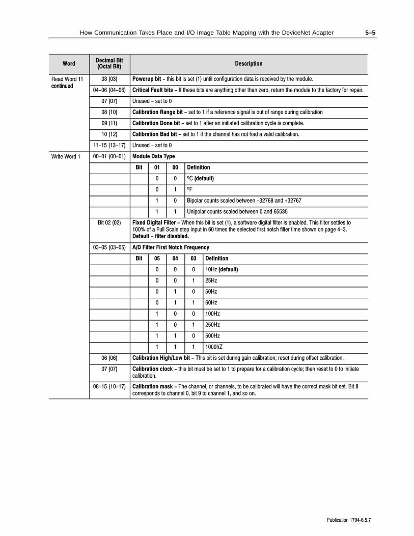
5–5How Communication Takes Place and I/O Image Table Mapping with the DeviceNet Adapter
Publication 17946.5.7
DescriptionDecimal Bit(Octal Bit)Word
Read Word 11continued
03 (03) Powerup bit - this bit is set (1) until configuration data is received by the module.continued
04-06 (04-06) Critical Fault bits - If these bits are anything other than zero, return the module to the factory for repair.
07 (07) Unused - set to 0
08 (10) Calibration Range bit - set to 1 if a reference signal is out of range during calibration
09 (11) Calibration Done bit - set to 1 after an initiated calibration cycle is complete.
10 (12) Calibration Bad bit - set to 1 if the channel has not had a valid calibration.
11-15 (13-17) Unused - set to 0
Write Word 1 00-01 (00-01) Module Data Type
Bit 01 00 Definition
0 0 oC (default)
0 1 oF
1 0 Bipolar counts scaled between -32768 and +32767
1 1 Unipolar counts scaled between 0 and 65535
Bit 02 (02) Fixed Digital Filter - When this bit is set (1), a software digital filter is enabled. This filter settles to100% of a Full Scale step input in 60 times the selected first notch filter time shown on page 4-3.Default - filter disabled.
03-05 (03-05) A/D Filter First Notch Frequency
Bit 05 04 03 Definition
0 0 0 10Hz (default)
0 0 1 25Hz
0 1 0 50Hz
0 1 1 60Hz
1 0 0 100Hz
1 0 1 250Hz
1 1 0 500Hz
1 1 1 1000hZ
06 (06) Calibration High/Low bit - This bit is set during gain calibration; reset during offset calibration.
07 (07) Calibration clock - this bit must be set to 1 to prepare for a calibration cycle; then reset to 0 to initiatecalibration.
08-15 (10-17) Calibration mask - The channel, or channels, to be calibrated will have the correct mask bit set. Bit 8corresponds to channel 0, bit 9 to channel 1, and so on.
5–6 How Communication Takes Place and I/O Image Table Mapping with the DeviceNet Adapter
Publication 17946.5.7
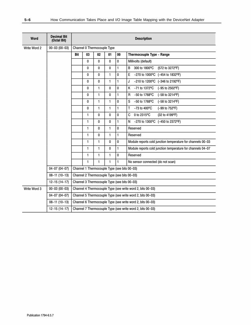
DescriptionDecimal Bit(Octal Bit)Word
Write Word 2 00-03 (00-03) Channel 0 Thermocouple Type
Bit 03 02 01 00 Thermocouple Type - Range
0 0 0 0 Millivolts (default)
0 0 0 1 B 300 to 1800oC (572 to 3272oF)
0 0 1 0 E -270 to 1000oC (-454 to 1832oF)
0 0 1 1 J -210 to 1200oC (-346 to 2192oF)
0 1 0 0 K -71 to 1372oC (-95 to 2502oF)
0 1 0 1 R -50 to 1768oC (-58 to 3214oF)
0 1 1 0 S -50 to 1768oC (-58 to 3214oF)
0 1 1 1 T -73 to 400oC (-99 to 752oF)
1 0 0 0 C 0 to 2315oC (32 to 4199oF)
1 0 0 1 N -270 to 1300oC (-450 to 2372oF)
1 0 1 0 Reserved
1 0 1 1 Reserved
1 1 0 0 Module reports cold junction temperature for channels 00-03
1 1 0 1 Module reports cold junction temperature for channels 04-07
1 1 1 0 Reserved
1 1 1 1 No sensor connected (do not scan)
04-07 (04-07) Channel 1 Thermocouple Type (see bits 00-03)
08-11 (10-13) Channel 2 Thermocouple Type (see bits 00-03)
12-15 (14-17) Channel 3 Thermocouple Type (see bits 00-03)
Write Word 3 00-03 (00-03) Channel 4 Thermocouple Type (see write word 2, bits 00-03)
04-07 (04-07) Channel 5 Thermocouple Type (see write word 2, bits 00-03)
08-11 (10-13) Channel 6 Thermocouple Type (see write word 2, bits 00-03)
12-15 (14-17) Channel 7 Thermocouple Type (see write word 2, bits 00-03)
5–7How Communication Takes Place and I/O Image Table Mapping with the DeviceNet Adapter
Publication 17946.5.7
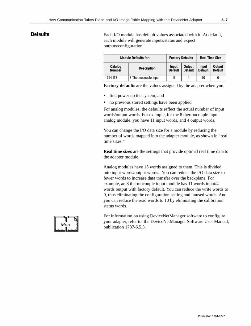
Each I/O module has default values associated with it. At default,each module will generate inputs/status and expectoutputs/configuration.
Module Defaults for: Factory Defaults Real Time Size
CatalogNumber
DescriptionInput
DefaultOutputDefault
InputDefault
OutputDefault
1794IT8 8 Thermocouple Input 11 4 10 0
Factory defaults are the values assigned by the adapter when you:
• first power up the system, and
• no previous stored settings have been applied.
For analog modules, the defaults reflect the actual number of inputwords/output words. For example, for the 8 thermocouple inputanalog module, you have 11 input words, and 4 output words.
You can change the I/O data size for a module by reducing thenumber of words mapped into the adapter module, as shown in “realtime sizes.”
Real time sizes are the settings that provide optimal real time data tothe adapter module.
Analog modules have 15 words assigned to them. This is dividedinto input words/output words. You can reduce the I/O data size tofewer words to increase data transfer over the backplane. Forexample, an 8 thermocouple input module has 11 words input/4words output with factory default. You can reduce the write words to0, thus eliminating the configuration setting and unused words. Andyou can reduce the read words to 10 by eliminating the calibrationstatus words.
For information on using DeviceNetManager software to configureyour adapter, refer to the DeviceNetManager Software User Manual,publication 1787-6.5.3.More
Defaults
Chapter 6
Publication 17946.5.7
Calibrating Your Module
In this chapter we tell you:
• what tools are needed to calibrate
• how to calibrate out lead wire resistance
• calibrate your module manually
• calibrate your module using DeviceNetManager software
Your module is shipped to you already calibrated. If a calibrationcheck is required,follow the procedure below.
Perform module calibration periodically, based on your application.
Module calibration may also be required to remove module error dueto aging of components
In addition, calibration may be required to eliminate long lead wireresistance to open circuit detection current. See “Error Due to OpenCircuit Current Through Loop Resistance” in Appendix A.
Calibration can be accomplished using any of the following methods:
• manual calibration, as described below.
• 6200 I/O CONFIGURATION software (version 5.2 or later)–refer to your 6200 software publications for procedures forcalibrating.
• DeviceNetManager Software – refer to your DeviceNetManagersoftware documentation for the DeviceNet Adapter Module, Cat.No. 1794-ADN. Some portion of this calibration is included herefor use by personnel proficient with DeviceNet Adapterconfiguration software.
Important: You can use a 1794-TB2 or -TB3 terminal base unit ifyou are using the thermocouple/mV module in themillivolt mode only. You must use a 1794-TB3Tterminal base unit for all thermocouple uses.
Chapter Objective
General Information
6–2 Calibrating Your Module
Publication 17946.5.7
In order to calibrate your thermocouple input module you will needthe following tools and equipment:
Tool or Equipment Description
Precision Voltage Sourceor
0-100mV, 1µV resolutionAnalogic 3100, Data Precision 8200or equivalent
or Thermocouple Simulatorand Calibration source
Thermocouple Simulator/CalibratorModel 1120
Ectron Corporation8159 Engineer RoadSan Diego, CA 921111980
Industrial Terminal and Interconnect Cable
Programming terminal for A-B family processors
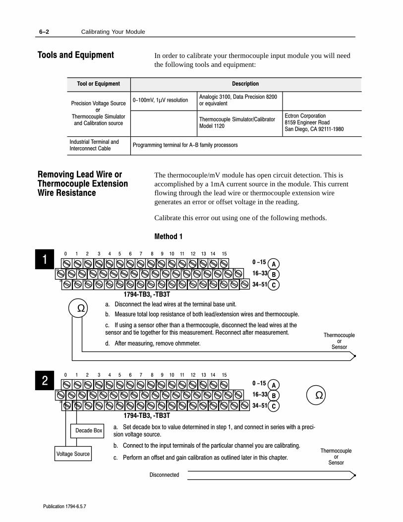
The thermocouple/mV module has open circuit detection. This isaccomplished by a 1mA current source in the module. This currentflowing through the lead wire or thermocouple extension wiregenerates an error or offset voltage in the reading.
Calibrate this error out using one of the following methods.
Method 1
17 18 19 20 21 22 23 24 25 26 27 28 29 30 31 32 33
0 1 2 3 4 5 6 7 8 9 10 11 12 13 14 15
16
1 2 3 4 5 6 7 8 9 10 11 12 13 14 150
35 36 37 38 39 40 41 42 43 44 45 46 47 48 49 50 5134
1794TB3, TB3T
0 -15
34-51
16-33
A
B
C
Ωb. Measure total loop resistance of both lead/extension wires and thermocouple.
1
Thermocoupleor
Sensor
c. If using a sensor other than a thermocouple, disconnect the lead wires at thesensor and tie together for this measurement. Reconnect after measurement.
d. After measuring, remove ohmmeter.
a. Disconnect the lead wires at the terminal base unit.
17 18 19 20 21 22 23 24 25 26 27 28 29 30 31 32 33
0 1 2 3 4 5 6 7 8 9 10 11 12 13 14 15
16
1 2 3 4 5 6 7 8 9 10 11 12 13 14 150
35 36 37 38 39 40 41 42 43 44 45 46 47 48 49 50 5134
1794TB3, TB3T
0 -15
34-51
16-33
A
B
C
Ω
a. Set decade box to value determined in step 1, and connect in series with a precision voltage source.
2
Decade Box
Voltage Source
b. Connect to the input terminals of the particular channel you are calibrating.
c. Perform an offset and gain calibration as outlined later in this chapter.Thermocouple
orSensor
Disconnected
Tools and Equipment
Removing Lead Wire orThermocouple ExtensionWire Resistance
6–3Calibrating Your Module
Publication 17946.5.7
17 18 19 20 21 22 23 24 25 26 27 28 29 30 31 32 33
0 1 2 3 4 5 6 7 8 9 10 11 12 13 14 15
16
1 2 3 4 5 6 7 8 9 10 11 12 13 14 150
35 36 37 38 39 40 41 42 43 44 45 46 47 48 49 50 5134
1794TB3, TB3T
0 -15
34-51
16-33
A
B
C
Ω3
Thermocoupleor
Sensor
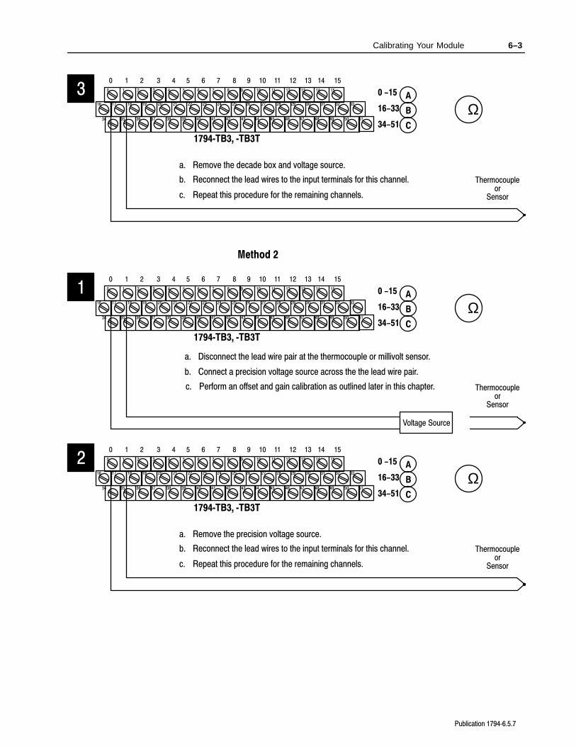
a. Remove the decade box and voltage source.
b. Reconnect the lead wires to the input terminals for this channel.
c. Repeat this procedure for the remaining channels.
Method 2
17 18 19 20 21 22 23 24 25 26 27 28 29 30 31 32 33
0 1 2 3 4 5 6 7 8 9 10 11 12 13 14 15
16
1 2 3 4 5 6 7 8 9 10 11 12 13 14 150
35 36 37 38 39 40 41 42 43 44 45 46 47 48 49 50 5134
1794TB3, TB3T
0 -15
34-51
16-33
A
B
C
Ω
b. Connect a precision voltage source across the the lead wire pair.
1
Voltage Source
c. Perform an offset and gain calibration as outlined later in this chapter. Thermocoupleor
Sensor
a. Disconnect the lead wire pair at the thermocouple or millivolt sensor.
17 18 19 20 21 22 23 24 25 26 27 28 29 30 31 32 33
0 1 2 3 4 5 6 7 8 9 10 11 12 13 14 15
16
1 2 3 4 5 6 7 8 9 10 11 12 13 14 150
35 36 37 38 39 40 41 42 43 44 45 46 47 48 49 50 5134
1794TB3, TB3T
0 -15
34-51
16-33
A
B
C
Ω2
Thermocoupleor
Sensor
a. Remove the precision voltage source.
b. Reconnect the lead wires to the input terminals for this channel.
c. Repeat this procedure for the remaining channels.
6–4 Calibrating Your Module
Publication 17946.5.7
You must calibrate the module in a FLEX I/O system. The modulemust communicate with the processor and a programming terminal.You can calibrate input channels in any order, or all at once.
Before calibrating your module, you must enter ladder logic into theprocessor memory, so that you can initiate BTWs to the module, andread inputs from the module.
Important: In order to allow the internal module temperature tostabilize, energize the module for at least 40 minutesbefore calibrating.
Module calibration consists of:
• Applying a reference to the desired input(s).
• Sending a message to the module indicating which inputs to readand what calibration step is being performed (offset).
The module stores this input data.
• Applying a second reference signal to the module, and sending asecond message indicating which inputs to read and whatcalibration step is being performed (gain).
The module computes new calibration values for the inputs.
Once the calibration is complete, the module reports back statusinformation about the procedure.
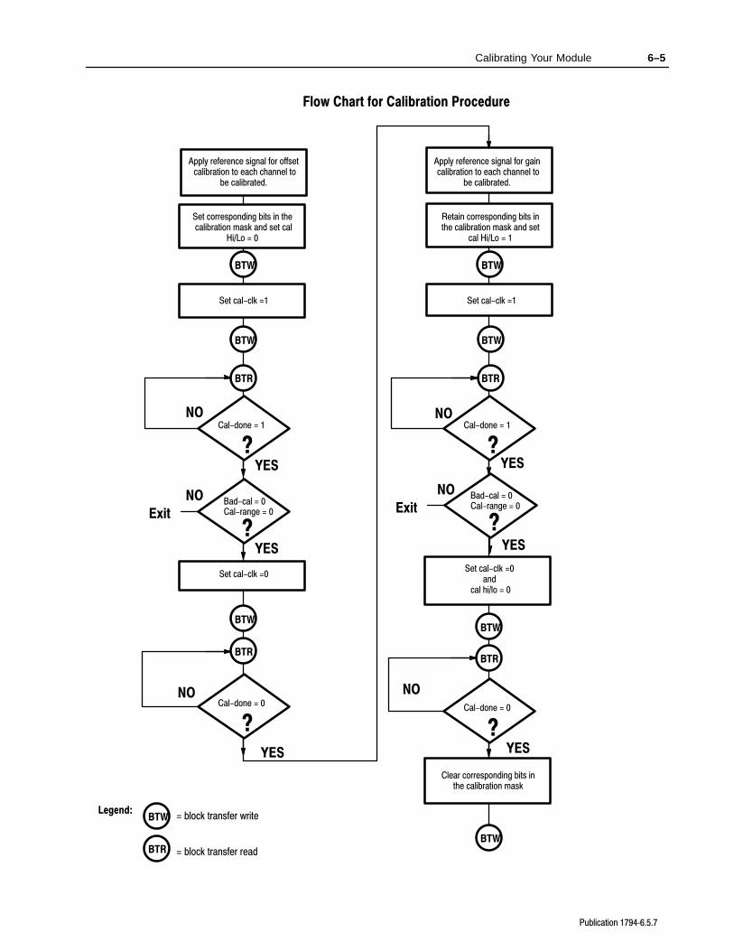
The following flow chart shows the procedure for calibration
Important: Perform the offset calibration procedure first, then thegain calibration procedure.
Manually Calibrating yourThermocouple/mV InputModule
6–5Calibrating Your Module
Publication 17946.5.7
Flow Chart for Calibration Procedure
Apply reference signal for offset calibration to each channel to
be calibrated.
Set corresponding bits in the calibration mask and set cal
Hi/Lo = 0
Set cal-clk =1
Set cal-clk =0
Cal-done = 1
?
NO
YES
NO
YES
Apply reference signal for gain calibration to each channel to
be calibrated.
Retain corresponding bits inthe calibration mask and set
cal Hi/Lo = 1
Set cal-clk =1
Set cal-clk =0 and
cal hi/lo = 0
NO
YES
NO
YES
Clear corresponding bits inthe calibration mask
BTR
Legend:
Cal-done = 0
?Cal-done = 0
?
Cal-done = 1
?
BTW
BTW
BTR
BTW
BTW
BTR
BTW
BTR
BTW
BTWBTR
BTW = block transfer write
= block transfer read
Bad-cal = 0
?
NO
YES
Exit Cal-range = 0
Bad-cal = 0
?
NO
YES
Exit Cal-range = 0
6–6 Calibrating Your Module
Publication 17946.5.7
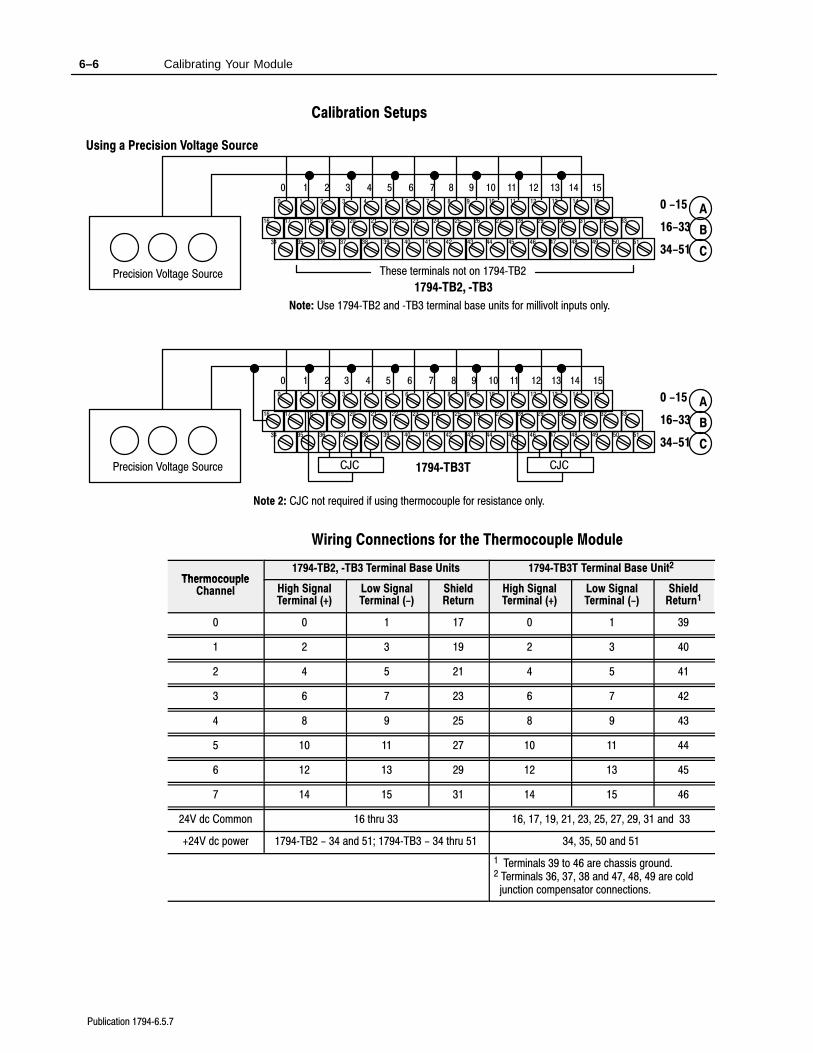
Calibration Setups
17 18 19 20 21 22 23 24 25 26 27 28 29 30 31 32 33
0 1 2 3 4 5 6 7 8 9 10 11 12 13 14 15
16
1 2 3 4 5 6 7 8 9 10 11 12 13 14 150
35 36 37 38 39 40 41 42 43 44 45 46 47 48 49 50 5134
1794TB2, TB3
0 -15
34-51
16-33
A
B
C
Precision Voltage Source
Using a Precision Voltage Source
CJC
17 18 19 20 21 22 23 24 25 26 27 28 29 30 31 32 33
0 1 2 3 4 5 6 7 8 9 10 11 12 13 14 15
16
1 2 3 4 5 6 7 8 9 10 11 12 13 14 150
35 36 37 38 39 40 41 42 43 44 45 46 47 48 49 50 5134
1794TB3T
0 -15
34-51
16-33
A
B
C
Precision Voltage Source CJC CJC
Note 2: CJC not required if using thermocouple for resistance only.
Note: Use 1794TB2 and TB3 terminal base units for millivolt inputs only.
These terminals not on 1794TB2
Wiring Connections for the Thermocouple Module
Thermocouple1794TB2, TB3 Terminal Base Units 1794TB3T Terminal Base Unit2
ThermocoupleChannel High Signal
Terminal (+)Low SignalTerminal (-)
ShieldReturn
High SignalTerminal (+)
Low SignalTerminal (-)
ShieldReturn1
0 0 1 17 0 1 39
1 2 3 19 2 3 40
2 4 5 21 4 5 41
3 6 7 23 6 7 42
4 8 9 25 8 9 43
5 10 11 27 10 11 44
6 12 13 29 12 13 45
7 14 15 31 14 15 46
24V dc Common 16 thru 33 16, 17, 19, 21, 23, 25, 27, 29, 31 and 33
+24V dc power 1794TB2 - 34 and 51; 1794TB3 - 34 thru 51 34, 35, 50 and 51
1 Terminals 39 to 46 are chassis ground.2 Terminals 36, 37, 38 and 47, 48, 49 are cold junction compensator connections.
6–7Calibrating Your Module
Publication 17946.5.7
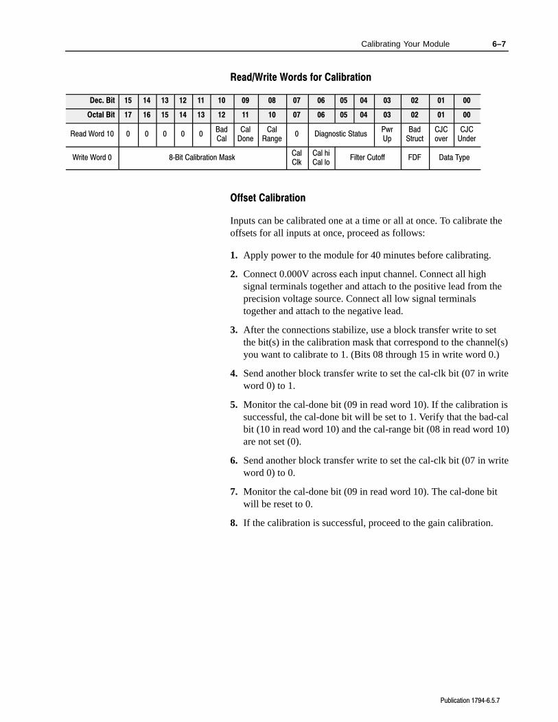
Read/Write Words for Calibration
Dec. Bit 15 14 13 12 11 10 09 08 07 06 05 04 03 02 01 00
Octal Bit 17 16 15 14 13 12 11 10 07 06 05 04 03 02 01 00
Read Word 10 0 0 0 0 0BadCal
CalDone
CalRange
0 Diagnostic StatusPwrUp
BadStruct
CJCover
CJCUnder
Write Word 0 8Bit Calibration MaskCalClk
Cal hiCal lo
Filter Cutoff FDF Data Type
Offset Calibration
Inputs can be calibrated one at a time or all at once. To calibrate theoffsets for all inputs at once, proceed as follows:
1. Apply power to the module for 40 minutes before calibrating.
2. Connect 0.000V across each input channel. Connect all highsignal terminals together and attach to the positive lead from theprecision voltage source. Connect all low signal terminalstogether and attach to the negative lead.
3. After the connections stabilize, use a block transfer write to setthe bit(s) in the calibration mask that correspond to the channel(s)you want to calibrate to 1. (Bits 08 through 15 in write word 0.)
4. Send another block transfer write to set the cal-clk bit (07 in writeword 0) to 1.
5. Monitor the cal-done bit (09 in read word 10). If the calibration issuccessful, the cal-done bit will be set to 1. Verify that the bad-calbit (10 in read word 10) and the cal-range bit (08 in read word 10)are not set (0).
6. Send another block transfer write to set the cal-clk bit (07 in writeword 0) to 0.
7. Monitor the cal-done bit (09 in read word 10). The cal-done bitwill be reset to 0.
8. If the calibration is successful, proceed to the gain calibration.
6–8 Calibrating Your Module
Publication 17946.5.7
Gain Calibration
After completing the offset calibration, proceed with the gaincalibration.
1. Apply power to the module for 40 minutes before calibrating.
2. Connect 75.000mV across each input channel. Connect all highsignal terminals together and attach to the positive lead from theprecision voltage source. Connect all low signal terminalstogether and attach to the negative lead.
3. After the connections stabilize, send a block transfer write to themodule to set the bit in the calibration mask that corresponds tothe channel to be calibrated to 1, and the hi/lo bit (bit 06 in writeword 0) to 1. (Set bits 08 through 15 in write word 0 if calibratingall inputs at one time.)
4. Send another block transfer write to set the cal-clk bit (07 in writeword 0) to 1.
5. Monitor the cal-done bit (09 in read word 10). If the calibration issuccessful, the cal-done bit will be set to 1. Verify that the bad-calbit (10 in read word 10) and the cal-range bit (08 in read word 10)are not set (0).
6. Send another BTW to set the cal-clk bit (07 in write word 0) to 0.
7. Send another BTW to set the hi/lo bit (bit 06 in write word 0)to 0.
8. Monitor the cal-done bit (09 in read word 10). The cal-done bitwill be reset to 0.
9. If individually calibrating channels, repeat steps 1 through 7 foroffset calibration on any additonal channels you want to calibrate.
10.Send a block transfer write to the module to clear all calibrationmask bits to 0.
6–9Calibrating Your Module
Publication 17946.5.7
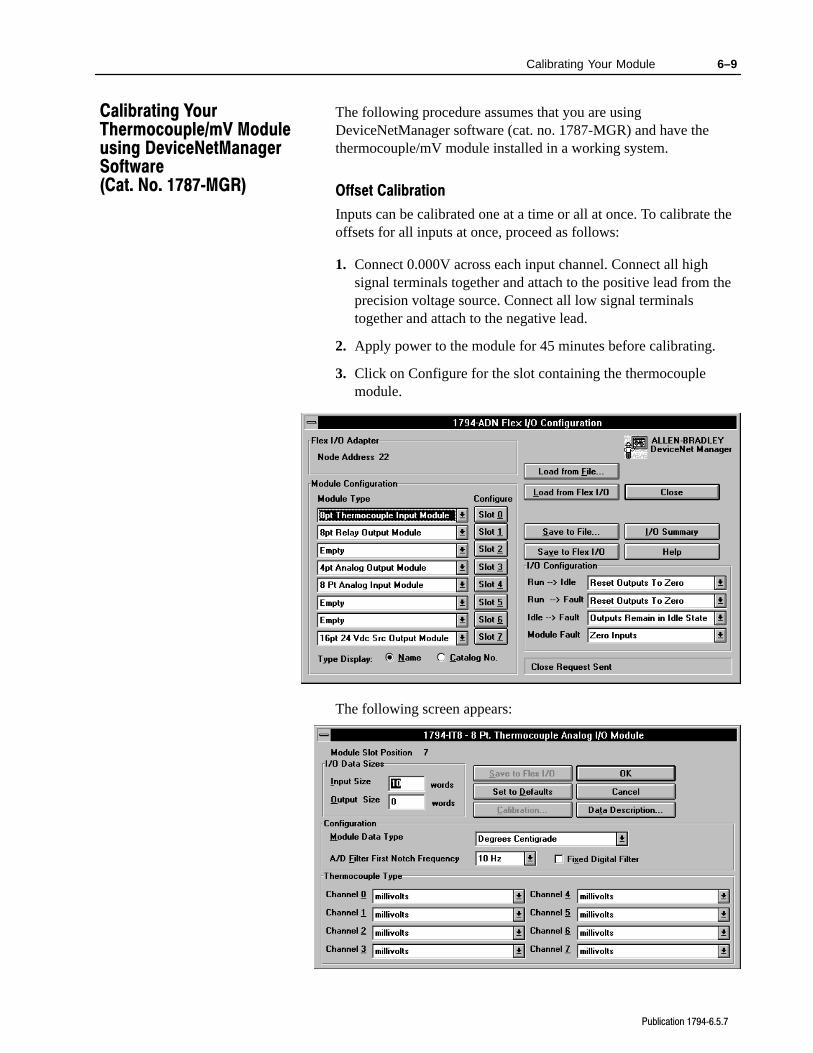
The following procedure assumes that you are usingDeviceNetManager software (cat. no. 1787-MGR) and have thethermocouple/mV module installed in a working system.
Offset Calibration
Inputs can be calibrated one at a time or all at once. To calibrate theoffsets for all inputs at once, proceed as follows:
1. Connect 0.000V across each input channel. Connect all highsignal terminals together and attach to the positive lead from theprecision voltage source. Connect all low signal terminalstogether and attach to the negative lead.
2. Apply power to the module for 45 minutes before calibrating.
3. Click on Configure for the slot containing the thermocouplemodule.
The following screen appears:
Calibrating YourThermocouple/mV Moduleusing DeviceNetManagerSoftware (Cat. No. 1787MGR)
6–10 Calibrating Your Module
Publication 17946.5.7
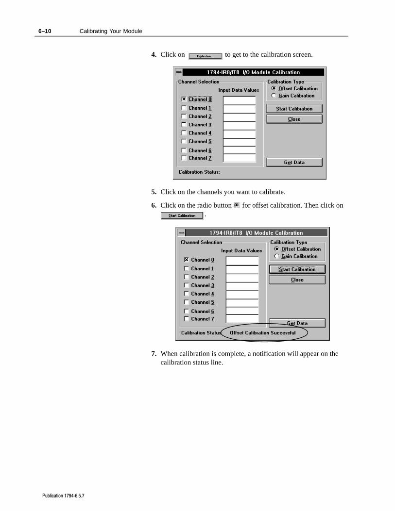
4. Click on to get to the calibration screen.
5. Click on the channels you want to calibrate.
6. Click on the radio button for offset calibration. Then click on.
7. When calibration is complete, a notification will appear on thecalibration status line.
6–11Calibrating Your Module
Publication 17946.5.7
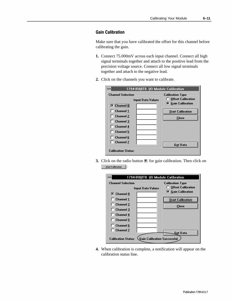
Gain Calibration
Make sure that you have calibrated the offset for this channel beforecalibrating the gain.
1. Connect 75.000mV across each input channel. Connect all highsignal terminals together and attach to the positive lead from theprecision voltage source. Connect all low signal terminalstogether and attach to the negative lead.
2. Click on the channels you want to calibrate.
3. Click on the radio button for gain calibration. Then click on.
4. When calibration is complete, a notification will appear on thecalibration status line.
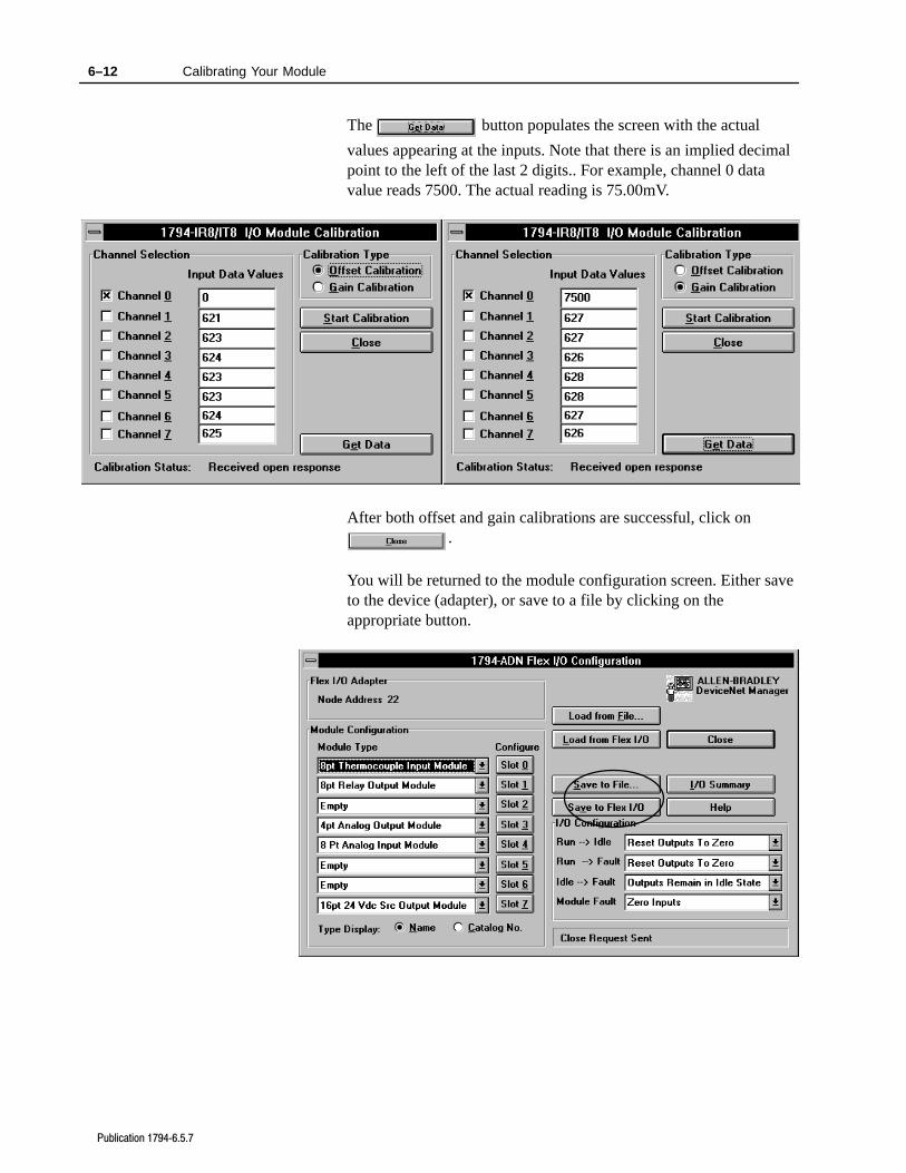
6–12 Calibrating Your Module
Publication 17946.5.7
The button populates the screen with the actual
values appearing at the inputs. Note that there is an implied decimalpoint to the left of the last 2 digits.. For example, channel 0 datavalue reads 7500. The actual reading is 75.00mV.
After both offset and gain calibrations are successful, click on.
You will be returned to the module configuration screen. Either saveto the device (adapter), or save to a file by clicking on theappropriate button.
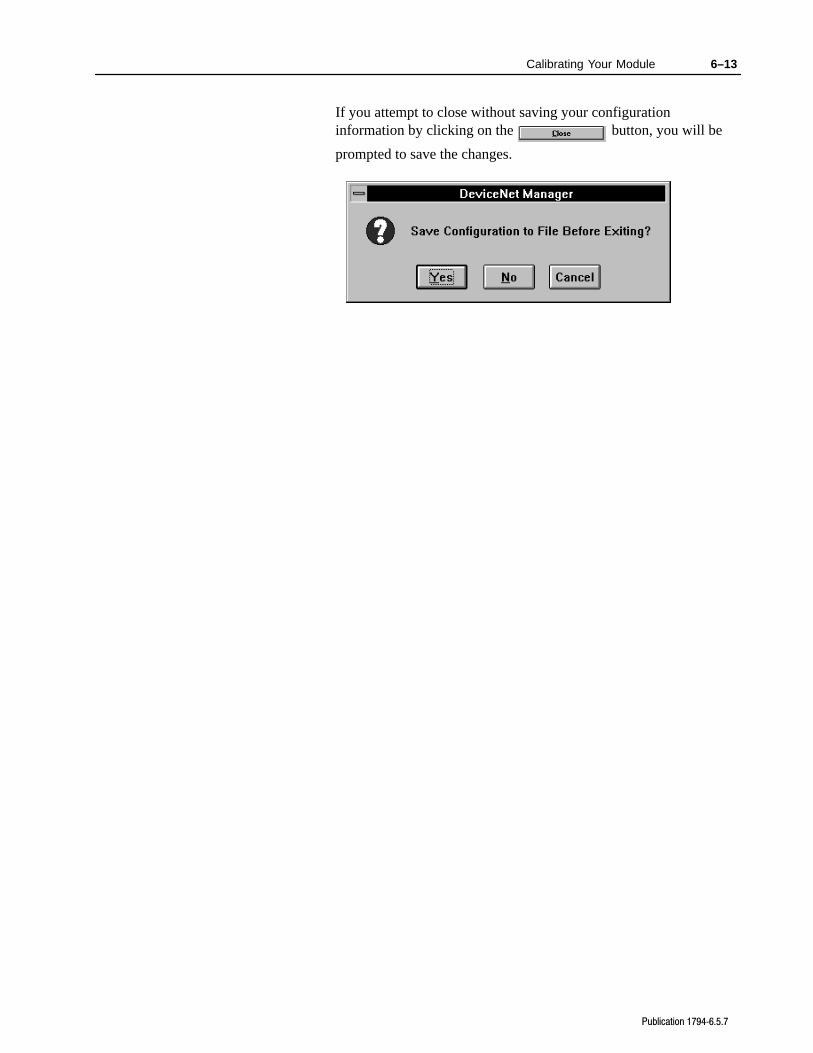
6–13Calibrating Your Module
Publication 17946.5.7
If you attempt to close without saving your configurationinformation by clicking on the button, you will be
prompted to save the changes.
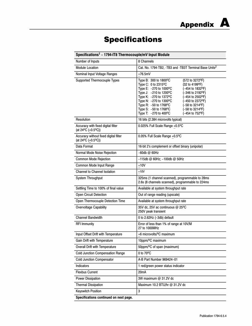
Appendix A
Publication 17946.5.4
Specifications
Specifications1 - 1794IT8 Thermocouple/mV Input Module
Number of Inputs 8 Channels
Module Location Cat. No. 1794TB2, TB3 and TB3T Terminal Base Units2
Nominal Input Voltage Ranges +76.5mV
Supported Thermocouple Types Type B: 300 to 1800oC (572 to 3272oF)Type C: 0 to 2315oC (32 to 4199oF)Type E: -270 to 1000oC (-454 to 1832oF)Type J: -210 to 1200oC (-346 to 2192oF)Type K: -270 to 1372oC (-454 to 2502oF)Type N: -270 to 1300oC (-450 to 2372oF)Type R: -50 to 1768oC (-58 to 3214oF)Type S: -50 to 1768oC (-58 to 3214oF)Type T: -270 to 400oC (-454 to 752oF)
Resolution 16 bits (2.384 microvolts typical)
Accuracy with fixed digital filter (at 24oC (+0.5oC))
0.025% Full Scale Range +0.5oC
Accuracy without fixed digital filter (at 24oC (+0.5oC))
0.05% Full Scale Range +0.5oC
Data Format 16bit 2's complement or offset binary (unipolar)
Normal Mode Noise Rejection -60db @ 60Hz
Common Mode Rejection -115db @ 60Hz; -100db @ 50Hz
Common Mode Input Range +10V
Channel to Channel Isolation +10V
System Throughput 325ms (1 channel scanned), programmable to 28ms2.6s (8 channels scanned), programmable to 224ms
Settling Time to 100% of final value Available at system throughput rate
Open Circuit Detection Out of range reading (upscale)
Open Thermocouple Detection Time Available at system throughput rate
Overvoltage Capability 35V dc, 25V ac continuous @ 25oC250V peak transient
Channel Bandwidth 0 to 2.62Hz (-3db) default
RFI Immunity Error of less than 1% of range at 10V/M27 to 1000MHz
Input Offset Drift with Temperature +6 microvolts/oC maximum
Gain Drift with Temperature 10ppm/oC maximum
Overall Drift with Temperature 50ppm/oC of span (maximum)
Cold Junction Compensation Range 0 to 70oC
Cold Junction Compensator AB Part Number 969424-01
Indicators 1 red/green power status indicator
Flexbus Current 20mA
Power Dissipation 3W maximum @ 31.2V dc
Thermal Dissipation Maximum 10.2 BTU/hr @ 31.2V dc
Keyswitch Position 3
Specifications continued on next page.
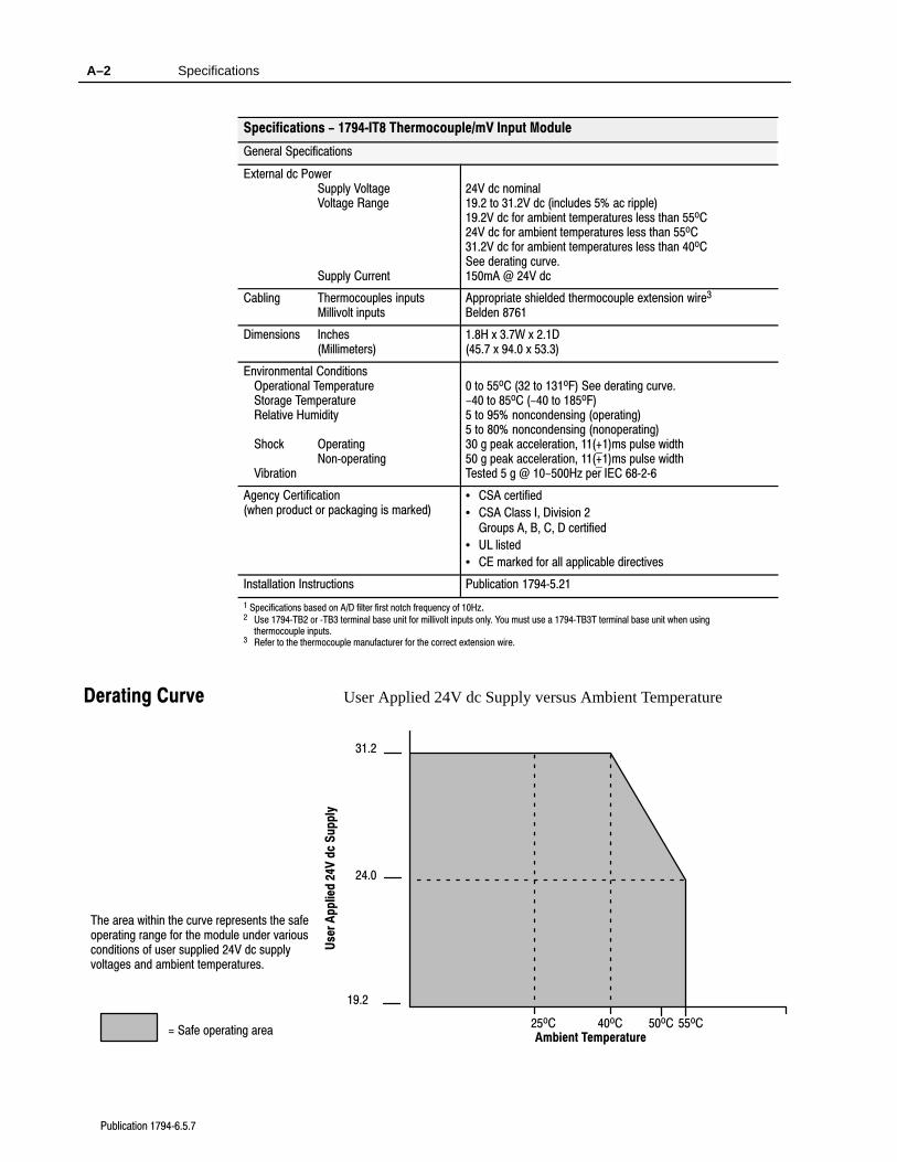
Specifications A–2
Publication 17946.5.7
Specifications - 1794IT8 Thermocouple/mV Input Module
General Specifications
External dc PowerSupply VoltageVoltage Range
Supply Current
24V dc nominal19.2 to 31.2V dc (includes 5% ac ripple)19.2V dc for ambient temperatures less than 55oC24V dc for ambient temperatures less than 55oC31.2V dc for ambient temperatures less than 40oCSee derating curve.150mA @ 24V dc
Cabling Thermocouples inputsMillivolt inputs
Appropriate shielded thermocouple extension wire3
Belden 8761
Dimensions Inches(Millimeters)
1.8H x 3.7W x 2.1D(45.7 x 94.0 x 53.3)
Environmental ConditionsOperational TemperatureStorage TemperatureRelative Humidity
Shock OperatingNonoperating
Vibration
0 to 55oC (32 to 131oF) See derating curve.-40 to 85oC (-40 to 185oF)5 to 95% noncondensing (operating)5 to 80% noncondensing (nonoperating)30 g peak acceleration, 11(+1)ms pulse width50 g peak acceleration, 11(+1)ms pulse widthTested 5 g @ 10-500Hz per IEC 6826
Agency Certification(when product or packaging is marked)
• CSA certified
• CSA Class I, Division 2Groups A, B, C, D certified
• UL listed
• CE marked for all applicable directives
Installation Instructions Publication 17945.21
1 Specifications based on A/D filter first notch frequency of 10Hz.2 Use 1794TB2 or TB3 terminal base unit for millivolt inputs only. You must use a 1794TB3T terminal base unit when using
thermocouple inputs.3 Refer to the thermocouple manufacturer for the correct extension wire.
User Applied 24V dc Supply versus Ambient Temperature
19.2
24.0
31.2
25oC 40oC 50oC 55oC
Use
r A
pp
lied
24V
dc
Su
pp
ly
Ambient Temperature
The area within the curve represents the safeoperating range for the module under variousconditions of user supplied 24V dc supplyvoltages and ambient temperatures.
= Safe operating area
Derating Curve
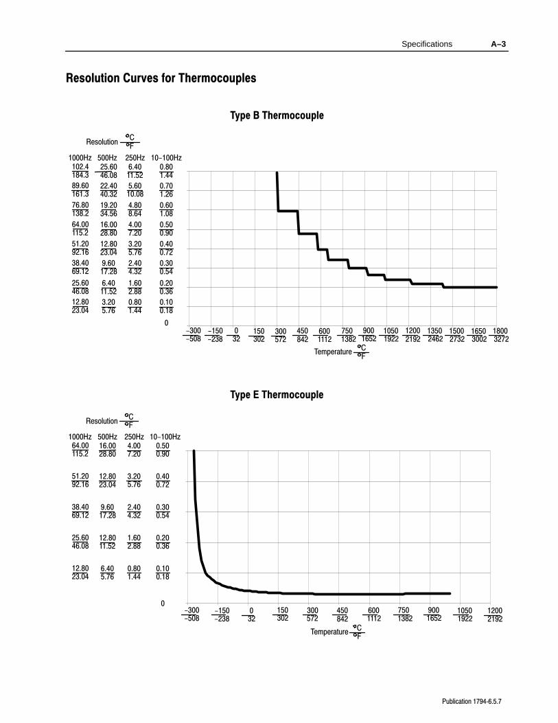
Specifications A–3
Publication 17946.5.7
Resolution Curves for Thermocouples
Type B Thermocouple
10-100Hz250Hz500Hz1000Hz
Resolution C F
0.801.44
6.4011.52
25.6046.08
102.4184.3
0.701.26
5.6010.08
22.4040.32
89.60161.3
0.601.08
4.808.64
19.2034.56
76.80138.2
0.500.90
4.007.20
16.0028.80
64.00115.2
0.400.72
3.205.76
12.8023.04
51.2092.16
0.300.54
2.404.32
9.6017.28
38.4069.12
0-300-508
-150-238
032
150302
300572
450842
15002732
7501382
9001652
10501922
12002192
Temperature C F
0.200.36
1.602.88
6.4011.52
25.6046.08
0.100.18
0.801.44
3.205.76
12.8023.04
6001112
13502462
18003272
16503002
Type E Thermocouple
10-100Hz250Hz500Hz1000Hz
Resolution C F
0.500.90
4.007.20
16.0028.80
64.00115.2
0.400.72
3.205.76
12.8023.04
51.2092.16
0.300.54
2.404.32
9.6017.28
38.4069.12
0.200.36
1.602.88
12.8011.52
25.6046.08
0.100.18
0.801.44
6.405.76
12.8023.04
0-300-508
-150-238
032
150302
300572
450842
6001112
7501382
9001652
10501922
12002192
Temperature C F
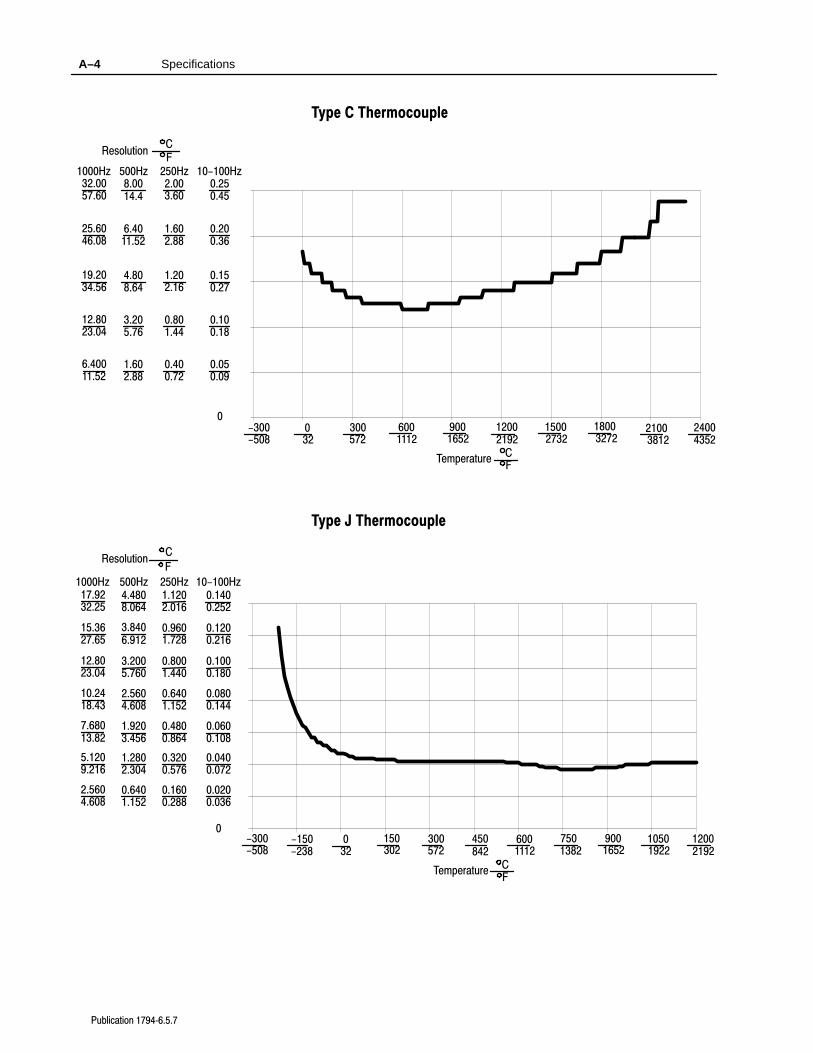
Specifications A–4
Publication 17946.5.7
Type C Thermocouple
10-100Hz250Hz500Hz1000Hz
Resolution C F
0.250.45
2.003.60
8.0014.4
32.0057.60
0.150.27
1.202.16
4.808.64
19.2034.56
0-300-508
032
300572
15002732
9001652
12002192
Temperature C F
0.200.36
1.602.88
6.4011.52
25.6046.08
0.100.18
0.801.44
3.205.76
12.8023.04
6001112
18003272
0.050.09
0.400.72
1.602.88
6.40011.52
21003812
24004352
Type J Thermocouple
10-100Hz250Hz500Hz1000Hz
Resolution C
F
0.1400.252
1.1202.016
4.4808.064
17.9232.25
0.1200.216
0.9601.728
3.8406.912
15.3627.65
0.1000.180
0.8001.440
3.2005.760
12.8023.04
0.0800.144
0.6401.152
2.5604.608
10.2418.43
0.0600.108
0.4800.864
1.9203.456
7.68013.82
0.0400.072
0.3200.576
1.2802.304
5.1209.216
0-300-508
-150-238
032
150302
300572
450842
6001112
7501382
9001652
10501922
12002192
Temperature C F
0.0200.036
0.1600.288
0.6401.152
2.5604.608
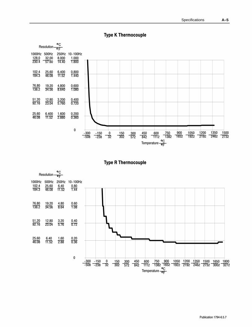
Specifications A–5
Publication 17946.5.7
Type K Thermocouple
10-100Hz250Hz500Hz1000Hz
Resolution C
F
1.0001.800
8.00014.40
32.0057.60
128.0230.4
0.8001.440
6.40011.52
25.6046.08
102.4184.3
0.6001.080
4.8008.640
19.2034.56
76.80138.2
0.4000.720
3.2005.760
12.8023.04
51.2092.16
0-300-508
-150-238
032
150302
300572
450842
6001112
7501382
9001652
10501922
15002732
Temperature C F
0.2000.360
1.6002.880
6.40011.52
25.6046.08
13502462
12002192
Type R Thermocouple
10-100Hz250Hz500Hz1000Hz
Resolution C F
0.801.44
6.4011.52
25.6046.08
102.4184.3
0.601.08
4.808.64
19.2034.56
76.80138.2
0.400.72
3.205.76
12.8023.04
51.2092.16
0-300-508
-150-238
032
150302
300572
450842
15002732
7501382
9001652
10501922
12002192
Temperature C F
0.200.36
1.602.88
6.4011.52
25.6046.08
6001112
13502462
18003272
16503002
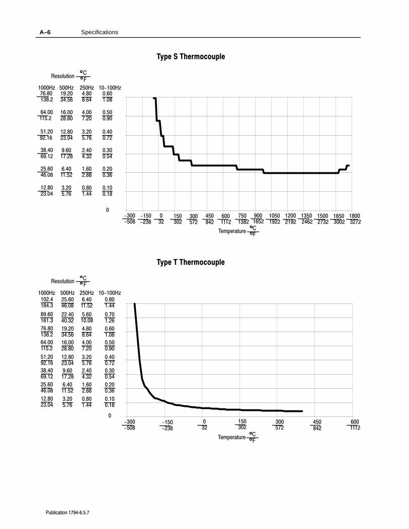
Specifications A–6
Publication 17946.5.7
Type S Thermocouple
10-100Hz250Hz500Hz1000Hz
Resolution C F
0.601.08
4.808.64
19.2034.56
76.80138.2
0.500.90
4.007.20
16.0028.80
64.00115.2
0.400.72
3.205.76
12.8023.04
51.2092.16
0.300.54
2.404.32
9.6017.28
38.4069.12
0-300-508
-150-238
032
150302
300572
450842
15002732
7501382
9001652
10501922
12002192
Temperature C F
0.200.36
1.602.88
6.4011.52
25.6046.08
0.100.18
0.801.44
3.205.76
12.8023.04
6001112
13502462
18003272
16503002
Type T Thermocouple
10-100Hz250Hz500Hz1000Hz
Resolution C F
0.801.44
6.4011.52
25.6046.08
102.4184.3
0.701.26
5.6010.08
22.4040.32
89.60161.3
0.601.08
4.808.64
19.2034.56
76.80138.2
0.500.90
4.007.20
16.0028.80
64.00115.2
0.400.72
3.205.76
12.8023.04
51.2092.16
0.300.54
2.404.32
9.6017.28
38.4069.12
0-300-508
-150-238
032
150302
300572
450842
Temperature C F
0.200.36
1.602.88
6.4011.52
25.6046.08
0.100.18
0.801.44
3.205.76
12.8023.04
6001112
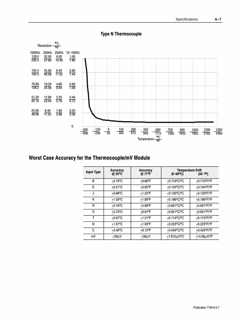
Specifications A–7
Publication 17946.5.7
Type N Thermocouple
10-100Hz250Hz500Hz1000Hz
Resolution C F
1.001.80
8.0014.40
32.0057.60
128.0230.4
0.601.08
4.808.64
19.2034.56
76.80138.2
0.400.72
3.205.76
12.8023.04
51.2092.16
0-300-508
-150-238
032
150302
300572
450842
7501382
9001652
10501922
12002192
Temperature C F
0.200.36
1.602.88
6.4011.52
25.6046.08
6001112
13502462
0.801.44
6.4011.52
25.6046.08
102.4184.3
Worst Case Accuracy for the Thermocouple/mV Module
Input TypeAccuracy@ 25oC
Accuracy@ 77oF
Temperature Drift (0-60oC) (32-oF)
B +3.70oC +6.66oF +0.710oC/oC +0.710oF/oF
E +0.51oC +0.92oF +0.104oC/oC +0.104oF/oF
J +0.68oC +1.22oF +0.130oC/oC +0.130oF/oF
K +1.00oC +1.80oF +0.186oC/oC +0.186oF/oF
R +3.16oC +5.69oF +0.601oC/oC +0.601oF/oF
S +3.70oC +6.67oF +0.651oC/oC +0.651oF/oF
T +0.67oC +1.21oF +0.174oC/oC +0.174oF/oF
N +1.07oC +1.93oF +0.223oC/oC +0.223oF/oF
C +3.40oC +6.12oF +0.434oC/oC +0.434oF/oF
mV +39µV +39µV +7.812µV/oC +14.06µV/oF
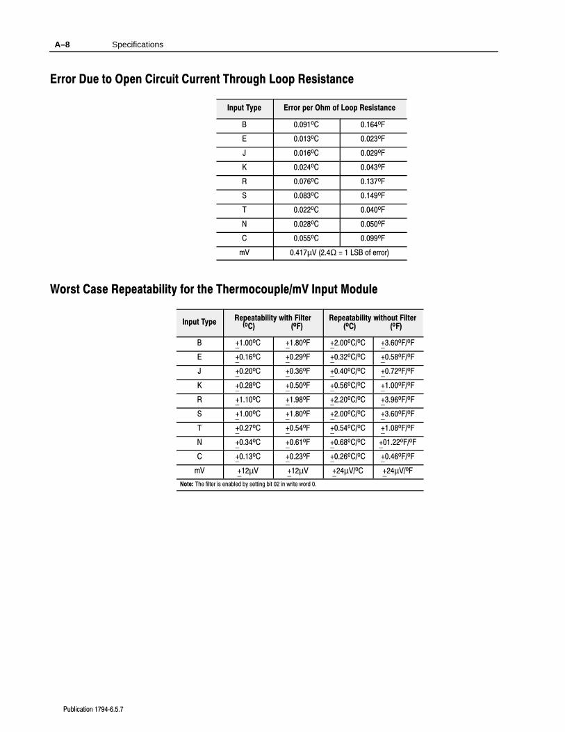
Specifications A–8
Publication 17946.5.7
Error Due to Open Circuit Current Through Loop Resistance
Input Type Error per Ohm of Loop Resistance
B 0.091oC 0.164oF
E 0.013oC 0.023oF
J 0.016oC 0.029oF
K 0.024oC 0.043oF
R 0.076oC 0.137oF
S 0.083oC 0.149oF
T 0.022oC 0.040oF
N 0.028oC 0.050oF
C 0.055oC 0.099oF
mV 0.417µV (2.4Ω = 1 LSB of error)
Worst Case Repeatability for the Thermocouple/mV Input Module
Input TypeRepeatability with Filter
(oC) (oF)Repeatability without Filter
(oC) (oF)
B +1.00oC +1.80oF +2.00oC/oC +3.60oF/oF
E +0.16oC +0.29oF +0.32oC/oC +0.58oF/oF
J +0.20oC +0.36oF +0.40oC/oC +0.72oF/oF
K +0.28oC +0.50oF +0.56oC/oC +1.00oF/oF
R +1.10oC +1.98oF +2.20oC/oC +3.96oF/oF
S +1.00oC +1.80oF +2.00oC/oC +3.60oF/oF
T +0.27oC +0.54oF +0.54oC/oC +1.08oF/oF
N +0.34oC +0.61oF +0.68oC/oC +01.22oF/oF
C +0.13oC +0.23oF +0.26oC/oC +0.46oF/oF
mV +12µV +12µV +24µV/oC +24µV/oF
Note: The filter is enabled by setting bit 02 in write word 0.
Appendix B
Publication 17946.5.7
Thermocouple Restrictions(Extracted from NBSMonograph 125 (IPTS-68))
Following are some restrictions extracted from NBS Monograph 125(IPTS–68) issued March 1974 on thermocouples B, E, J, K, R, Sand T:
B (Platinum - 30% Rhodium vs Platinum - 6% Rhodium) Type
Thermocouples
“The ASTM manual STP 470 [1970] indicates the followingrestrictions on the use of B type thermocouples at high temperatures:They should not be used in reducing atmospheres, nor in thosecontaining metallic or nonmetallic vapors, unless suitably protectedwiht nonmetallic protecting tubes. They should never be inserteddirectly into a metallic primary tube.”
“At temperatures below 450C the Seebeck coefficient of Type Bthermocouples becomes quite small and is almost negligible in thenormal room temperature range. Consequently, in most applicationsthe reference junction temperature of the thermocouple does notneed to be controlled or even known, as long as it is between 0 and50C.”
Studies have shown that “a 0.1 percent change in the Rhodiumcontent of the Pt–30% Rh thermoelement produces a correspondingchange in the thermocouple voltage of about 15uV (i.e. 1.3C) at1500C. In contrast a change of only .01% in the Rhodium content ofPt–6% Rh thermoelement also produces a voltage change of about15uV (1.3C) at this temperature.”
“The thermoelectric voltages of Type B thermocouples is sensitive totheir history of annealing, heat treatment and quenching. Calibrationof Type B wires above 1600C is undesirable in most circumstances.”
“ASTM Standard E230–72 in the Annual Book of ASTM Standards[1972] specifies that the standard limits of error for Type Bcommercial thermocouples be + 1/2 percent between 871 and 1705C.Limits of error are not specified for Type B thermocouples below871C. The recommended upper temperature limit for protectedthermocouples, 1705C, applies to AWG 24 (0.5mm) wire.”
General
Thermocouple Restrictions B–2
Publication 17946.5.7
E (Nickel-Chromium vs Copper-Nickel <Constantan*>) Type
Thermocouple
“Type E thermocouples are recommended by the ASTM Manual[1970] for use in the temperature range from –250 to 871C inoxidizing or inert atmospheres. The negative thermoelement issubject to deterioration above about 871C, but the thermocouple maybe used up to 1000C for short periods.”
“The ASTM Manual [1970] indicates the following restrictions .. athigh temperatures. They should not be used in sulfurous, reducing oralternately reducing and oxidizing atmospheres unless suitablyprotected with protecting tubes. They should not be used in vacuum(at high temperatures) for extended times, because the Chromium inthe positive thermoelement vaporizes out of solution and alters thecalibration. They should also not be used in atmospheres thatpromote ”green–rot” corrosion (those with low, but not negligible,oxygen content).”
“The negative thermoelement, a copper–nickel alloy, is subject tocomposition changes under thermal neutron irradiation since thecopper is converted to nickel and zinc.”
“ASTM Standard E230–72 in the Annual Book of ASTM Standards[1972] specifies that the standard limits of error for the Type Ecommercial thermocouples be +/–1.7C between 0 and 316C and+/–1/2 percent between 316 and 871C. Limits of error are notspecified for Type E thermocouples below 0C. Type Ethermocouples can also be supplied to meet special limits of error,which are less than the standard limits of error given above:+/–1.25C between 0 and 316C and +/–3/8 percent between 316 and871C. The recommended upper temperature limit for protectedthermocouples, 871C, applies to AWG 8 (3.3mm) wire. For smallerwires the recommended upper temperature decreases to 649C forAWG 14 (1.6mm), 538C for AWG 20 (.8mm) and 427C for AWG 24or 28 (0.5 or 0.3mm).
J (Iron vs Copper-Nickel <Constantan*>) Type Thermocouple
The J thermocouple “is the least suitable for accurate thermometrybecause there are significant nonlinear deviations in thethermoelectric output from different manufacturers. ... The total andspecific types of impurities that occur in commercial iron changewith time, location of primary ores, and methods of smelting.”
Thermocouple Restrictions B–3
Publication 17946.5.7
“Type J thermocouples are recommended by the ASTM [1970] foruse in the temperature range from 0 to 760C in vacuum, oxidizing,reducing or inert atmospheres. If used for extended times above500C, heavy gage wires are recommended because the oxidation rateis rapid at elevated temperatures.”
“They should not be used in sulfurous atmospheres above 500C.Because of potential rusting and embrittlement, they are notrecommended for subzero temperatures. They should not be cycledabove 760C even for a short time if accurate readings below 760Care desired at a later time.”
“The negative thermoelement, a copper–nickel alloy, is subject tosubstantial composition changes under thermal neutron irradiation,since copper is converted to nickel and zinc.”
“Commercial iron undergoes a magnetic transformation near 769Cand <an alpha – gamma> crystal transformation near 910C. Both ofthese transformations, especially the latter, seriously affect thethermoelectric properties of iron, and therefore, the Type Jthermocouples. If Type J thermocouples are taken to hightemperatures, especially above 900C, they will lose accuracy of theircalibration when they are recycled to lower temperatures.”
“ASTM Standard E230–72 in the Annual Book of ASTM Standards[1972] specifies that the standard limits of error for Type Jcommercial thermocouples be +/–2.2C between 0 and 277C and+/–3/4 percent between 277 and 760C. Limits of error are notspecified for Type J thermocouples below 0C or above 760C. Type Jthermocouples can also be supplied to meet special limits of error,which are equal to one half the limits given above. Therecommended upper temperature limit for protected thermocouples,760C, applies to AWG 8 (3.3mm) wire. For smaller wires therecommended upper temperature decrease to 593C for AWG 14(1.6mm), and 371C for AWG 24 or 28 (0.5 or 0.3mm).
* It should be noted that the Constantan element of Type J thermoelements is NOT interchangeable
with the Constantan element of Types T or N due to the different ratio of copper and nickel
in each.
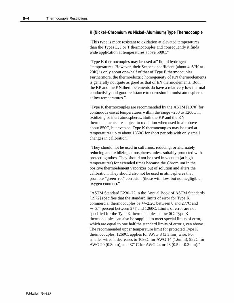
Thermocouple Restrictions B–4
Publication 17946.5.7
K (Nickel-Chromium vs Nickel-Aluminum) Type Thermocouple
“This type is more resistant to oxidation at elevated temperaturesthan the Types E, J or T thermocouples and consequently it findswide application at temperatures above 500C.”
“Type K thermocouples may be used at” liquid hydrogen“temperatures. However, their Seebeck coefficient (about 4uV/K at20K) is only about one–half of that of Type E thermocouples.Furthermore, the thermoelectric homogeneity of KN thermoelementsis generally not quite as good as that of EN thermoelements. Boththe KP and the KN thermoelements do have a relatively low thermalconductivity and good resistance to corrosion in moist atmospheresat low temperatures.”
“Type K thermocouples are recommended by the ASTM [1970] forcontinuous use at temperatures within the range –250 to 1260C inoxidizing or inert atmospheres. Both the KP and the KNthermoelements are subject to oxidation when used in air aboveabout 850C, but even so, Type K thermocouples may be used attemperatures up to about 1350C for short periods with only smallchanges in calibration.”
“They should not be used in sulfurous, reducing, or alternatelyreducing and oxidizing atmospheres unless suitably protected withprotecting tubes. They should not be used in vacuum (at hightemperatures) for extended times because the Chromium in thepositive thermoelement vaporizes out of solution and alters thecalibration. They should also not be used in atmospheres thatpromote ”green–rot” corrosion (those with low, but not negligible,oxygen content).”
“ASTM Standard E230–72 in the Annual Book of ASTM Standards[1972] specifies that the standard limits of error for Type Kcommercial thermocouples be +/–2.2C between 0 and 277C and+/–3/4 percent between 277 and 1260C. Limits of error are notspecified for the Type K thermocouples below 0C. Type Kthermocouples can also be supplied to meet special limits of error,which are equal to one half the standard limits of error given above.The recommended upper temperature limit for protected Type Kthermocouples, 1260C, applies for AWG 8 (3.3mm) wire. Forsmaller wires it decreases to 1093C for AWG 14 (1.6mm), 982C forAWG 20 (0.8mm), and 871C for AWG 24 or 28 (0.5 or 0.3mm).”
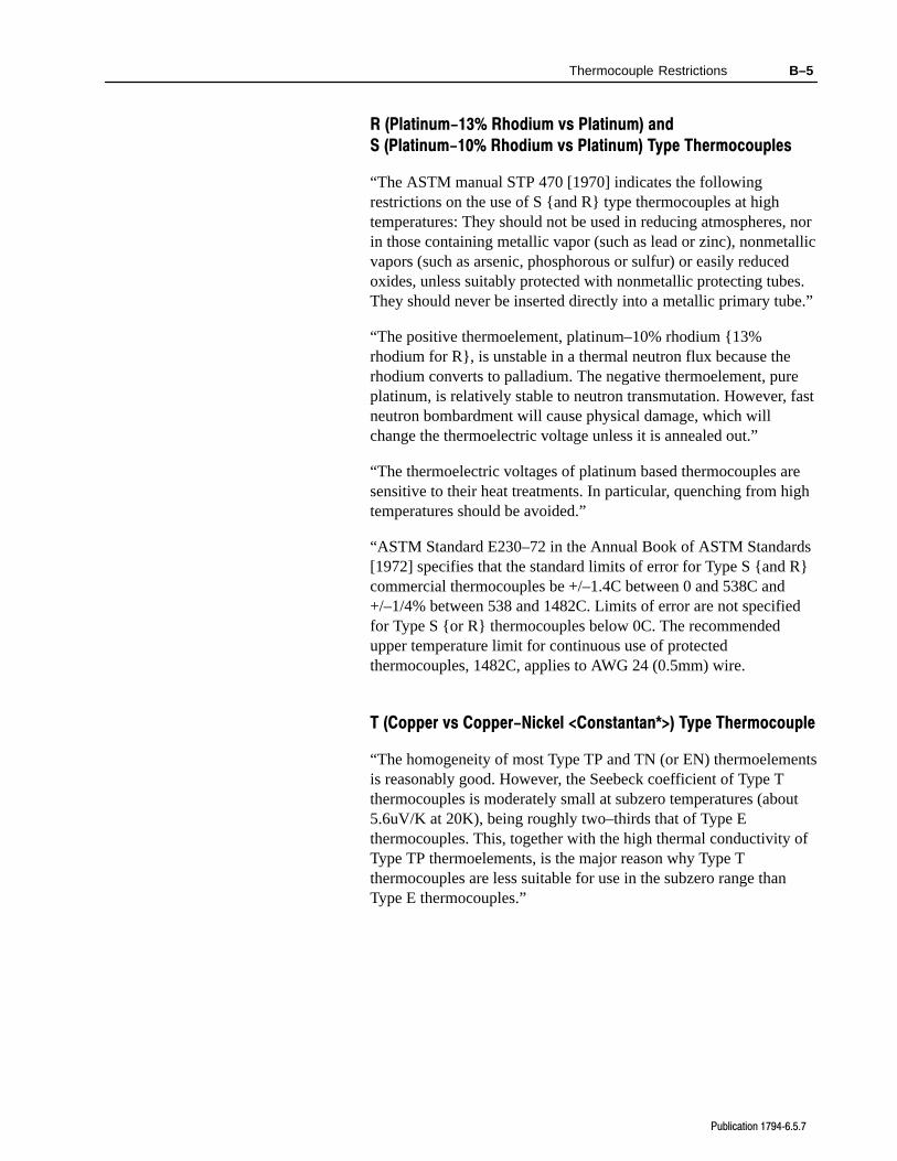
Thermocouple Restrictions B–5
Publication 17946.5.7
R (Platinum-13% Rhodium vs Platinum) and
S (Platinum-10% Rhodium vs Platinum) Type Thermocouples
“The ASTM manual STP 470 [1970] indicates the followingrestrictions on the use of S and R type thermocouples at hightemperatures: They should not be used in reducing atmospheres, norin those containing metallic vapor (such as lead or zinc), nonmetallicvapors (such as arsenic, phosphorous or sulfur) or easily reducedoxides, unless suitably protected with nonmetallic protecting tubes.They should never be inserted directly into a metallic primary tube.”
“The positive thermoelement, platinum–10% rhodium 13%rhodium for R, is unstable in a thermal neutron flux because therhodium converts to palladium. The negative thermoelement, pureplatinum, is relatively stable to neutron transmutation. However, fastneutron bombardment will cause physical damage, which willchange the thermoelectric voltage unless it is annealed out.”
“The thermoelectric voltages of platinum based thermocouples aresensitive to their heat treatments. In particular, quenching from hightemperatures should be avoided.”
“ASTM Standard E230–72 in the Annual Book of ASTM Standards[1972] specifies that the standard limits of error for Type S and Rcommercial thermocouples be +/–1.4C between 0 and 538C and+/–1/4% between 538 and 1482C. Limits of error are not specifiedfor Type S or R thermocouples below 0C. The recommendedupper temperature limit for continuous use of protectedthermocouples, 1482C, applies to AWG 24 (0.5mm) wire.
T (Copper vs Copper-Nickel <Constantan*>) Type Thermocouple
“The homogeneity of most Type TP and TN (or EN) thermoelementsis reasonably good. However, the Seebeck coefficient of Type Tthermocouples is moderately small at subzero temperatures (about5.6uV/K at 20K), being roughly two–thirds that of Type Ethermocouples. This, together with the high thermal conductivity ofType TP thermoelements, is the major reason why Type Tthermocouples are less suitable for use in the subzero range thanType E thermocouples.”
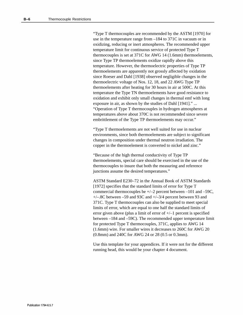
Thermocouple Restrictions B–6
Publication 17946.5.7
“Type T thermocouples are recommended by the ASTM [1970] foruse in the temperature range from –184 to 371C in vacuum or inoxidizing, reducing or inert atmospheres. The recommended uppertemperature limit for continuous service of protected Type Tthermocouples is set at 371C for AWG 14 (1.6mm) thermoelements,since Type TP thermoelements oxidize rapidly above thistemperature. However, the thermoelectric properties of Type TPthermoelements are apparently not grossly affected by oxidationsince Roeser and Dahl [1938] observed negligible changes in thethermoelectric voltage of Nos. 12, 18, and 22 AWG Type TPthermoelements after heating for 30 hours in air at 500C. At thistemperature the Type TN thermoelements have good resistance tooxidation and exhibit only small changes in thermal emf with longexposure in air, as shown by the studies of Dahl [1941].” ...“Operation of Type T thermocouples in hydrogen atmospheres attemperatures above about 370C is not recommended since severeembrittlement of the Type TP thermoelements may occur.”
“Type T thermoelements are not well suited for use in nuclearenvironments, since both thermoelements are subject to significantchanges in composition under thermal neutron irradiation. Thecopper in the thermoelement is converted to nickel and zinc.”
“Because of the high thermal conductivity of Type TPthermoelements, special care should be exercised in the use of thethermocouples to insure that both the measuring and referencejunctions assume the desired temperatures.”
ASTM Standard E230–72 in the Annual Book of ASTM Standards[1972] specifies that the standard limits of error for Type Tcommercial thermocouples be +/–2 percent between –101 and –59C,+/–.8C between –59 and 93C and +/–3/4 percent between 93 and371C. Type T thermocouples can also be supplied to meet speciallimits of error, which are equal to one half the standard limits oferror given above (plus a limit of error of +/–1 percent is specifiedbetween –184 and –59C). The recommended upper temperature limitfor protected Type T thermocouples, 371C, applies to AWG 14(1.6mm) wire. For smaller wires it decreases to 260C for AWG 20(0.8mm) and 240C for AWG 24 or 28 (0.5 or 0.3mm).
Use this template for your appendices. If it were not for the differentrunning head, this would be your chapter 4 document.
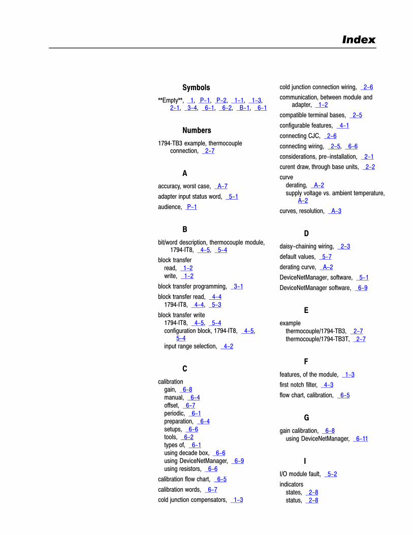
Symbols
**Empty**, 1, P-1, P-2, 1-1, 1-3, 2-1, 3-4, 6-1, 6-2, B-1, 6-1
Numbers
1794TB3 example, thermocoupleconnection, 2-7
A
accuracy, worst case, A-7
adapter input status word, 5-1
audience, P-1
B
bit/word description, thermocouple module,1794IT8, 4-5, 5-4
block transferread, 1-2write, 1-2
block transfer programming, 3-1
block transfer read, 4-41794IT8, 4-4, 5-3
block transfer write1794IT8, 4-5, 5-4configuration block, 1794IT8, 4-5,
5-4input range selection, 4-2
C
calibrationgain, 6-8manual, 6-4offset, 6-7periodic, 6-1preparation, 6-4setups, 6-6tools, 6-2types of, 6-1using decade box, 6-6using DeviceNetManager, 6-9using resistors, 6-6
calibration flow chart, 6-5
calibration words, 6-7
cold junction compensators, 1-3
cold junction connection wiring, 2-6
communication, between module andadapter, 1-2
compatible terminal bases, 2-5
configurable features, 4-1
connecting CJC, 2-6
connecting wiring, 2-5, 6-6
considerations, pre-installation, 2-1
curent draw, through base units, 2-2
curvederating, A-2supply voltage vs. ambient temperature,
A-2
curves, resolution, A-3
D
daisy-chaining wiring, 2-3
default values, 5-7
derating curve, A-2
DeviceNetManager, software, 5-1
DeviceNetManager software, 6-9
E
examplethermocouple/1794TB3, 2-7thermocouple/1794TB3T, 2-7
F
features, of the module, 1-3
first notch filter, 4-3
flow chart, calibration, 6-5
G
gain calibration, 6-8using DeviceNetManager, 6-11
I
I/O module fault, 5-2
indicatorsstates, 2-8status, 2-8
Index
IndexI–2
input ranges, 4-2
input scaling, 4-2
input status word, 5-2
installation, module, 2-4
K
keyswitch positions, 2-4
M
manual calibration, 6-4
mapping, 1794IT8, 4-4, 5-3
module, shipping state, 6-1
module fault, 5-2
module features, 1-3
module installation, 2-4
O
offset calibration, 6-7using DeviceNetManager, 6-9
open circuit error, A-8
optimal defaults, 5-7
P
PLC-2 programming, 3-4
polled I/O, structure, 5-1
power defaults, 5-7
preparing for calibration, 6-4
programming examplePLC-3, 3-2PLC-5, 3-3
R
range, selecting, 4-2
read/write words, for calibration, 6-7
removing and replacing, under power(RIUP), 2-4
repeatability, worst case, A-8
resolution curves, A-3type B thermocouple, A-3type C thermocouple, A-4type E thermocouple, A-3type J thermocouple, A-4type K thermocouple, A-5type N thermocouple, A-7type R thermocouple, A-5type S thermocouple, A-6type T thermocouple, A-6
S
sample program, 3-4
scaling, 4-2
software, DeviceNetManager, 5-1
specifications, thermocouple, A-1
status indicators, 2-8
system throughput, 5-3
T
terminal bases, compatible, 2-5
thermocouple input mapping, 1794IT8, 4-4, 5-3
thermocouple/1794TB3T example, 2-7
throughput, normal mode, 4-3
W
wiringconnections, 6-6methods of, 2-3to terminal bases, 2-1
wiring connections, 2-51794IT8, 2-6, 6-6
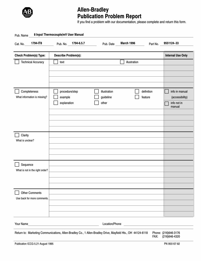
AllenBradleyPublication Problem ReportIf you find a problem with our documentation, please complete and return this form.
Pub. Name
Cat. No. Pub. No. Pub. Date Part No.
Check Problem(s) Type: Describe Problem(s): Internal Use Only
procedure/step
example
explanation
illustration
guideline
other
definition
feature
info in manual
(accessibility)
info not inmanual
text illustrationTechnical Accuracy
Completeness
What information is missing?
Clarity
Sequence
What is not in the right order?
What is unclear?
Other Comments
Use back for more comments.
Your Name Location/Phone
Return to: Marketing Communications, AllenBradley Co., 1 AllenBradley Drive, Mayfield Hts., OH 441246118 Phone: (216)6463176FAX: (216)6464320
Publication ICCG5.21August 1995 PN 95510782
8 Input Thermocouple/mV User Manual
1794IT8 17946.5.7 9551124-33March 1996

Other Comments
PLEASE FOLD HERE
NO POSTAGE NECESSARY
IF MAILED IN THE
UNITED STATES
BUSINESS REPLY MAILFIRST-CLASS MAIL PERMIT NO. 18235 CLEVELAND OH
POSTAGE WILL BE PAID BY THE ADDRESSEE
1 ALLEN BRADLEY DRMAYFIELD HEIGHTS OH 44124-9705
PLE
AS
E R
EM
OV
E
PLEASE FASTEN HERE (DO NOT STAPLE)

At Allen-Bradley, customer service means experiencedrepresentatives at Customer Support Centers in key cities throughoutthe world for sales service and support. Our value-added servicesinclude:
Technical Support
• SupportPlus programs
• telephone support and 24-hour emergency hotline
• software and documentation updates
• technical subscription services
Engineering and Field Services
• application engineering assistance
• integration and start-up assistance
• field service
• maintenance support
Technical Training
• lecture and lab courses
• self-paced computer and video-based training
• job aids and workstations
• training needs analysis
Repair and Exchange Services
• your only “authorized” source
• current revisions and enhancements
• worldwide exchange inventory
• local support
Support Services

Publication 17946.5.7 - March 1996 PN955124-33Copyright 1996 AllenBradley Company, Inc. Printed in USA
AllenBradley, a Rockwell Automation Business, has been helping its customers improveproductivity and quality for more than 90 years. We design, manufacture and support a broadrange of automation products worldwide. They include logic processors, power and motioncontrol devices, operator interfaces, sensors and a variety of software. Rockwell is one of theworld's leading technology companies.
Worldwide representation.
Argentina • Australia • Austria • Bahrain • Belgium • Brazil • Bulgaria • Canada • Chile • China, PRC • Colombia • Costa Rica • Croatia • Cyprus • Czech Republic •Denmark • Ecuador • Egypt • El Salvador • Finland • France • Germany • Greece • Guatemala • Honduras • Hong Kong • Hungary • Iceland • India • Indonesia •
Ireland • Israel • Italy • Jamaica • Japan • Jordan • Korea • Kuwait • Lebanon • Malaysia • Mexico • Netherlands • New Zealand • Norway • Pakistan • Peru •Philippines • Poland • Portugal • Puerto Rico • Qatar • Romania • Russia-CIS • Saudi Arabia • Singapore • Slovakia • Slovenia • South Africa, Republic • Spain •Sweden • Switzerland • Taiwan • Thailand • Turkey • United Arab Emirates • United Kingdom • United States • Uruguay • Venezuela • Yugoslavia
AllenBradley Headquarters, 1201 South Second Street, Milwaukee, WI 53204 USA, Tel: (1) 414 3822000 Fax: (1) 414 3824444