Embed Size (px)
Citation preview
American Journal of Renewable and Sustainable Energy
Vol. 1, No. 2, 2015, pp. 31-38
http://www.aiscience.org/journal/ajrse
* Corresponding author
E-mail address: [email protected] (A. Ataei)
Thermodynamic Performance Analysis of Different Organic Rankine Cycles to Generate Power from Renewable Energy Resources
Abtin Ataei1, 2, *, Farid Safari1, Jun-Ki Choi2
1Department of Energy Engineering, Graduate School of the Environment and Energy, Science and Research Branch, Islamic Azad University,
Tehran, Iran 2Mechanical and Aerospace Engineering / Renewable and Clean Energy, University of Dayton, Dayton, Ohio, USA
Abstract
Organic Rankine cycles (ORCs), are promising technologies for generating power from low and medium grade of heat
resources such as geothermal fluids or the synthetic gas from biomass gasification, that have received lots of attention during
past twenty years. In this study, thermodynamic evaluations were used based on the first and second laws of thermodynamics
to compare different organic fluids and different configuration of Rankine cycles. Energy and Exergy analysis of different
configurations of ORCs including basic ORC, basic ORC with Internal Heat Exchanger (IHE), Regenerative ORC and
Regenerative ORC with IHE for four dry organic fluids including R113, RC318, iso-pentane and n-hexane, in various ambient
temperatures, were simulated using Engineering Equation Solver (EES). In addition, environmental performances were
evaluated using the sustainability index method which was resulted from Exergy analysis. The results indicated that the
Regenerative ORC with IHE has the best thermodynamic performance with thermal and second law efficiency of 0.217 and
0.642, respectively. It was concluded that the n-hexane which has the highest boiling point and critical temperature is the most
efficient working fluid for the cycle. The results indicated that a reduction in ambient temperature causes an increment in both
thermal and second law efficiencies and makes the system more sustainable due to an increment in the sustainability index.
Keywords
Exergy Destruction, Regeneration, Heat Exchanger, Sustainability Index
Received: June 8, 2015 / Accepted: June 18, 2015 / Published online: July 8, 2015
@ 2015 The Authors. Published by American Institute of Science. This Open Access article is under the CC BY-NC license.
http://creativecommons.org/licenses/by-nc/4.0/
1. Introduction
Renewable energy is one of the key options for approaching
energy security and sustainable development in modern era.
These kinds of energy resources such as solar, biomass, wind,
geothermal and tidal energy have a great potential for
generating power and because of their reliability and
availability, researchers paid lots of attention to them, in the
last decades. One of them is geothermal energy that is always
available and comes from earth's crust. The Major world's
geothermal energy applications are a 12GW electricity
production and a direct use for heating of 23 GW in 2013 [1].
Organic Rankine cycles are promising technologies for
development and conversion of low and medium grade heat
resources into power. For three decades many researchers
have worked on this subject and have used scientific
fundamentals for more efficient and suitable conversion of
these kinds of energy resources into power in power plants.
ORCs work with Traditional Clausius-Rankine principles but
use organic dry fluids instead of water [2]. That makes them
able to generate power and remain superheat after expansion
in turbine in low and medium temperatures. The process of
making electricity from renewable energy resource should be
32 Abtin Ataei et al.: Thermodynamic Performance Analysis of Different Organic Rankine Cycles to Generate Power from
Renewable Energy Resources
economically viable. Some new methods have been proposed
for overcoming this challenge such as a value-based planning
method for combined cooling, heating and power (CCHP)
placement based on the energy hub concepts or Feed-In-
Tariff (FIT) policies which are regarded as one of the
efficient strategies in stimulating renewable energy
development [3,4].
In case of ORC's, an appropriate fluid should be used to
obtain the maximum thermal efficiency and minimum exergy
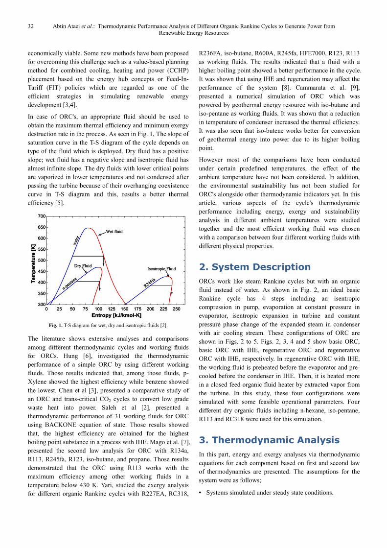
destruction rate in the process. As seen in Fig. 1, The slope of
saturation curve in the T-S diagram of the cycle depends on
type of the fluid which is deployed. Dry fluid has a positive
slope; wet fluid has a negative slope and isentropic fluid has
almost infinite slope. The dry fluids with lower critical points
are vaporized in lower temperatures and not condensed after
passing the turbine because of their overhanging coexistence
curve in T-S diagram and this, results a better thermal
efficiency [5].
Fig. 1. T-S diagram for wet, dry and isentropic fluids [2].
The literature shows extensive analyses and comparisons
among different thermodynamic cycles and working fluids
for ORCs. Hung [6], investigated the thermodynamic
performance of a simple ORC by using different working
fluids. Those results indicated that, among those fluids, p-
Xylene showed the highest efficiency while benzene showed
the lowest. Chen et al [3], presented a comparative study of
an ORC and trans-critical CO2 cycles to convert low grade
waste heat into power. Saleh et al [2], presented a
thermodynamic performance of 31 working fluids for ORC
using BACKONE equation of state. Those results showed
that, the highest efficiency are obtained for the highest
boiling point substance in a process with IHE. Mago et al. [7],
presented the second law analysis for ORC with R134a,
R113, R245fa, R123, iso-butane, and propane. Those results
demonstrated that the ORC using R113 works with the
maximum efficiency among other working fluids in a
temperature below 430 K. Yari, studied the exergy analysis
for different organic Rankine cycles with R227EA, RC318,
R236FA, iso-butane, R600A, R245fa, HFE7000, R123, R113
as working fluids. The results indicated that a fluid with a
higher boiling point showed a better performance in the cycle.
It was shown that using IHE and regeneration may affect the
performance of the system [8]. Cammarata et al. [9],
presented a numerical simulation of ORC which was
powered by geothermal energy resource with iso-butane and
iso-pentane as working fluids. It was shown that a reduction
in temperature of condenser increased the thermal efficiency.
It was also seen that iso-butene works better for conversion
of geothermal energy into power due to its higher boiling
point.
However most of the comparisons have been conducted
under certain predefined temperatures, the effect of the
ambient temperature have not been considered. In addition,
the environmental sustainability has not been studied for
ORC's alongside other thermodynamic indicators yet. In this
article, various aspects of the cycle's thermodynamic
performance including energy, exergy and sustainability
analysis in different ambient temperatures were studied
together and the most efficient working fluid was chosen
with a comparison between four different working fluids with
different physical properties.
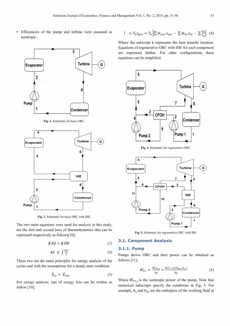
2. System Description
ORCs work like steam Rankine cycles but with an organic
fluid instead of water. As shown in Fig. 2, an ideal basic
Rankine cycle has 4 steps including an isentropic
compression in pump, evaporation at constant pressure in
evaporator, isentropic expansion in turbine and constant
pressure phase change of the expanded steam in condenser
with air cooling stream. These configurations of ORC are
shown in Figs. 2 to 5. Figs. 2, 3, 4 and 5 show basic ORC,
basic ORC with IHE, regenerative ORC and regenerative
ORC with IHE, respectively. In regenerative ORC with IHE,
the working fluid is preheated before the evaporator and pre-
cooled before the condenser in IHE. Then, it is heated more
in a closed feed organic fluid heater by extracted vapor from
the turbine. In this study, these four configurations were
simulated with some feasible operational parameters. Four
different dry organic fluids including n-hexane, iso-pentane,
R113 and RC318 were used for this simulation.
3. Thermodynamic Analysis
In this part, energy and exergy analyses via thermodynamic
equations for each component based on first and second law
of thermodynamics are presented. The assumptions for the
system were as follows;
• Systems simulated under steady state conditions.
American Journal of Economics, Finance and Management Vol. 1, No. 2, 2015, pp. 31-38 33
• Efficiencies of the pump and turbine were assumed as
isentropic.
Fig. 2. Schematic for basic ORC.
Fig. 3. Schematic for basic ORC with IHE.
The two main equations were used for analysis in this study,
are the first and second laws of thermodynamics that can be
expressed respectively as follows[10];
∮�� � ∮�� (1)
∆� �� (2)
These two are the main principles for energy analysis of the
cycles and with the assumptions for a steady state condition;
���� ������ (3)
For exergy analysis, rate of exergy loss can be written as
follow [10];
�� � ������� � �� �∑�� ������� �∑�� ����� �∑ ��� �
(4)
Where the subscript k represents the heat transfer location.
Equations of regenerative ORC with IHE for each component
are expressed further. For other configurations these
equations can be simplified.
Fig. 4. Schematic for regenerative ORC.
Fig. 5. Schematic for regenerative ORC with IHE.
3.1. Component Analysis
3.1.1. Pump
Pumps derive ORC and their power can be obtained as
follows [11];
�� !" �#� $%,'()
� *� +",-.+/0'1/%.()
(5)
Where �� !",2 is the isentropic power of the pump. Note that
numerical subscripts specify the conditions in Fig. 5. For
example, 3"and 342 are the enthalpies of the working fluid at

34 Abtin Ataei et al.: Thermodynamic Performance Analysis of Different Organic Rankine Cycles to Generate Power from
Renewable Energy Resources
inlet and outlet of the pump, respectively. Furthermore, 56 is
the isentropic efficiency and7 is the fraction of flow rate that
extracted from the turbine. Actual specific enthalpy at the
outlet is as follow;
34 � 3" + #� $%*� +",-. (6)
The exergy destruction rate for the pump can be written as
follow;
��6 � ���� +1 � 7.+�4 ��". (7)
Where �4 and �" are the specific entropies of the working
fluid at outlet and inlet of the pump in an actual condition.
Similarly to pump1, those equations can be written for pump
2 as follows [10];
�� !4 �#� $%%,'()
=*� -(/%%'1/%:)
() (8)
ℎ"" = ℎ"� +#� $0
*� - (9)
��!4 =���7� (�4 −�") (10)
3.1.2. Evaporator
The evaporator is where the heat transfer in constant pressure
occurs. This component heats the working fluid from the
pump outlet to turbine inlet condition which can be saturated
or superheated. The evaporator's heat transfer can be written
as follow;
��� =�� (ℎ; −ℎ<) (11)
The exergy destruction in the evaporator can also be written
as;
��� =���� [(�; −�<) − />,/?
@] (12)
Where, �A is the high temperature of heat source. This
temperature is equal to �;+∆�B so that ∆�B is 15 degrees of
Kelvin and specified via mago et al. [7]
3.1.3. Turbine
Turbine generates mechanical power by expansion of the
saturated or superheated working fluid and depressurizes it
by turbine blades. Turbine's power, actual outlet, specific
enthalpy and exergy destruction rate are expressed,
respectively as follows;
�� � = �� �" +�� �4=�� [(ℎ;,ℎC2) + (1 − 7)(ℎC,ℎD2)]5� (13)
ℎC = ℎ; −#� F%
*� (14)
ℎD = ℎC −#� F0
*� (",-) (15)
�� =���� [(�D −�;) − 7(�D −�C)] (16)
3.1.4. Condenser
The working fluid goes through a constant pressure
condensation in the condenser and becomes saturated liquid
for pumping condition. This process gives latent heat to the
environment that can be expressed as follow;
��G =�� (ℎ" −ℎH) (17)
Furthermore, exergy loss for the condenser can be
determined as;
��� =���� [(�" −�H) − /%,/I
J] (18)
Where �K is the low temperature of heat source. This
temperature is equal to �" − ∆�K so that ∆�L is 15 degrees of
Kelvin and specified via mago et al. [7]
3.1.5. Internal Heat Exchanger
With Ideal assumption, and neglecting pressure drop, the
process in IHE would be a constant pressure heat transfer. In
IHE, compressed liquid from pump gives heat to expanded
organic vapor coming from turbine's outlet. Heat transfer rate
in IHE can be described as
�� MAN =�� (ℎO −ℎ4) = �� (ℎD −ℎH) (19)
Also, the effectiveness of IHE is determined as follow;
PMAN
= Q, I
Q, 0 (20)
And finally, the exergy destruction rate for IHE is calculated
as follow;
��MAN =���� (1 − 7)[(�H −�D) + (�O −�4)] (21)
3.1.6. Close Feed Organic Fluid Heater
(CFOH)
CFOH in this study is a way to regenerate energy from the
expanded steam at turbine's outlet for preheating the liquid
pumped from the circulation pump without any mixing. With
balancing the mass and energy, the following equation is
used to calculate the mass fraction extracted from the turbine;
7 =(/R,/S)
(/R,/S)T(/U,/%:) (22)
And, the exergy destruction rate in CFOH is;
��VWXA =���� [(1 − 7)�Y + 7�"� − 7�C − (1 − 7)(�O)] (23)
3.2. Overall Cycle Analysis
3.2.1. Cycle Efficiency
Thermal efficiency is described as the quantity of the heat
transferred in evaporator that converted into work in turbine
and expressed as;
American Journal of Economics, Finance and Management Vol. 1, No. 2, 2015, pp. 31-38 35
5�/ � (Z[\]#� F,#� $��[
=#�^[_��[
(24)
3.2.2. Total Exergy Destruction Rate
Total exergy destruction rate is a parameter to determine the
cycle's reversibility and its potential to convert the low or
medium heat from renewable resources into useful work. The
exergy destruction should be minimized in order to achieve a
more sustainable system. That rate can be written for the
cycle as the following equation [11];
�� ��`a ����� [/?,/> J
� +1 � 7./I,/% J
] (25)
3.2.3. Second Law Efficiency
The second law efficiency can be calculated by as the
following equation [10];
5MM � #�^[_#� b[c
� #�^[_��[+",F:
F@. (26)
3.2.4. Sustainability Index (SI)
Sustainability index (SI) method have been deployed in this
article to realize the environmental problems and the
sustainability of the systems. The relation between the
second low efficiency and SI is mentioned as below[12];
�� � "",(dd
� "e)
(27)
Where Dp is the depletion factor defined by Connelly and
Koshland [13] as the ratio of exergy destruction rate to the
input exergy rate of the system and can be given as [14]
follow;
f6 � NghNgi^
(28)
SI is in to indicate how much exergy is destroyed in the
system. With these analysis, different configurations of ORC
with different working fluids were simulated by engineering
equation solver program (EES) and a comparison between
different configurations of ORC were done. Moreover,
variation of the thermal efficiency, the exergy destruction rate
and second law efficiency with the turbine inlet pressure and
ambient temperature, were investigated. It should be
mentioned that in this investigation, the optimum pressure of
the extracted flow from the turbine goes into CFOH for R113,
was determined according to Wark and Richard [15] as
follows;
jNk � 0.29jN�.;<;O For regenerative ORC (29)
jNk � 0.405jN�.C<Y"< For regenerative ORC with IHE (30)
Table 1 summarizes the basic assumptions and input
parameters of the simulation in this work. In order to
determine the performance of the system with variation of
the turbine inlet pressure and ambient temperature, it is
assumed that the system works at turbine inlet pressures
between 0.5 and 3 Mpa, and the temperature is between 283
and 313 degrees of Kelvin to determine the optimum
conditions for the cycle. The efficiencies of some different
components were chosen from the literatures as shown in
Table 1.
Table 1. Parameters used in this simulation.
Parameter Value Ref.
jN[rst] 0.5 – 3
jNk[rst] 0.29jN�.;<;Ofor regenerative ORC [15]
jNk[rst] 0.405jN�.C<Y"< for regenerative ORC
With IHE [15]
56[%] 75 [5]
5�[%] 80 [5],[7],[16]
5*�G/[%] 96 [17]
PMAN 0.9 [18]
∆�A,[K],∆�G[K] 15 [7]
��[v] 283-313
�G[v] 283-313
Table 2. Properties of the dry organic fluids used in this study.
Organic
fluid
Molecular
weight[g/mol] Boiling
point [k] Tcritical
[k] wxyz{zx|}[Mpa]
n-Hexane 86.17 341.9 507.4 3.01
Iso Pentane 72.15 301.1 460.4 3.38
R113 187.4 320.4 487.3 3.44
RC318 200.04 267.2 388.4 2.78
Table 2, includes working fluids that were used in this study
and their properties. Four different boiling points and critical
conditions associated with four different working fluids, were
selected to determine how these may affect the performance
parameters of the cycle.
4. Results and Discussion
The results of this study were presented in four parts. The
first part is a comparison between four configurations
presented in Figs. 2 to 5 in a constant operational condition
with R113 as the working fluid. These four configurations
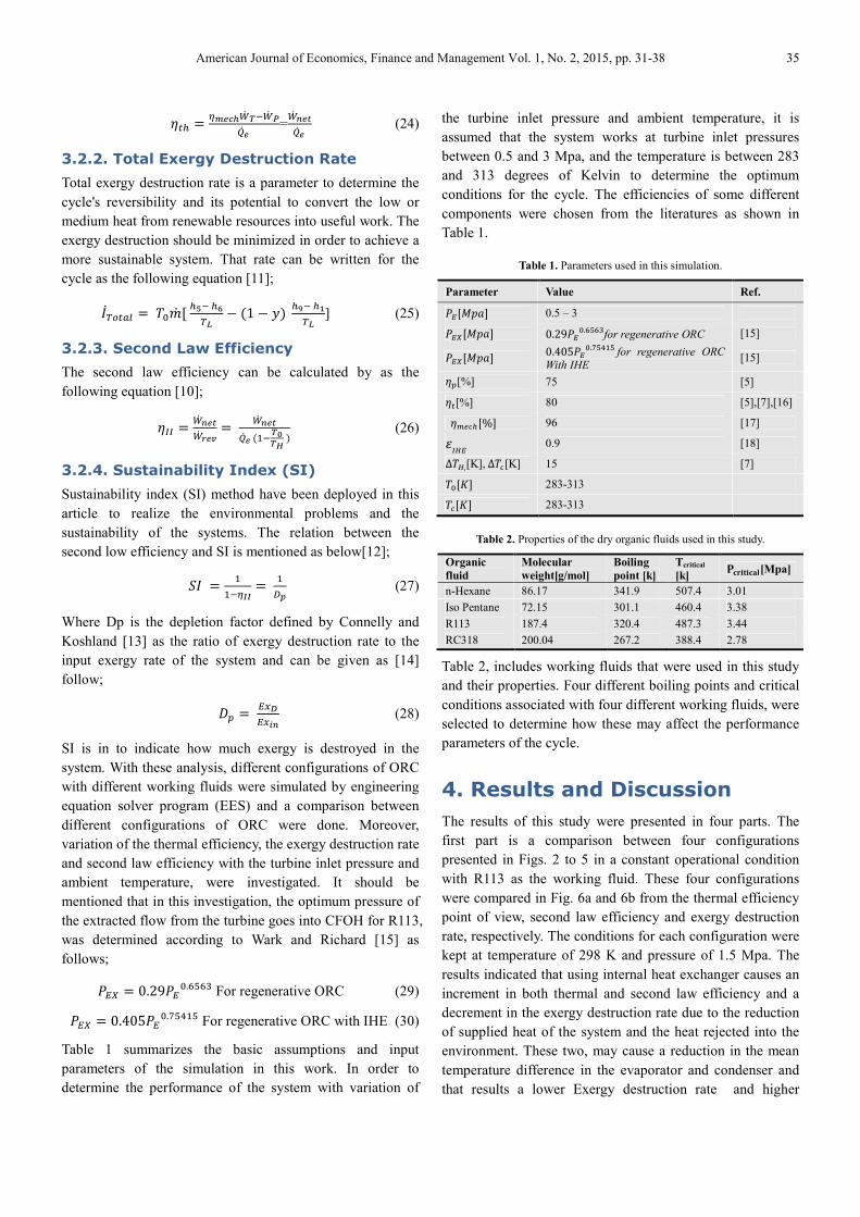
were compared in Fig. 6a and 6b from the thermal efficiency
point of view, second law efficiency and exergy destruction
rate, respectively. The conditions for each configuration were
kept at temperature of 298 K and pressure of 1.5 Mpa. The
results indicated that using internal heat exchanger causes an
increment in both thermal and second law efficiency and a
decrement in the exergy destruction rate due to the reduction
of supplied heat of the system and the heat rejected into the
environment. These two, may cause a reduction in the mean
temperature difference in the evaporator and condenser and
that results a lower Exergy destruction rate and higher
36 Abtin Ataei et al.: Thermodynamic Performance Analysis of Different Organic Rankine Cycles to Generate Power from
Renewable Energy Resources
second law efficiency. Furthermore, as seen in equation (24),
the reduction in heat supply with same turbine inlet
conditions occurs in higher thermal efficiencies. As seen in
Fig. 6, the ORC with IHE shows a 26% increment of thermal
efficiency in comparison with the basic ORC.
(a)
(b)
Fig. 6. Thermal and second-law efficiencies for different configurations of
ORC.
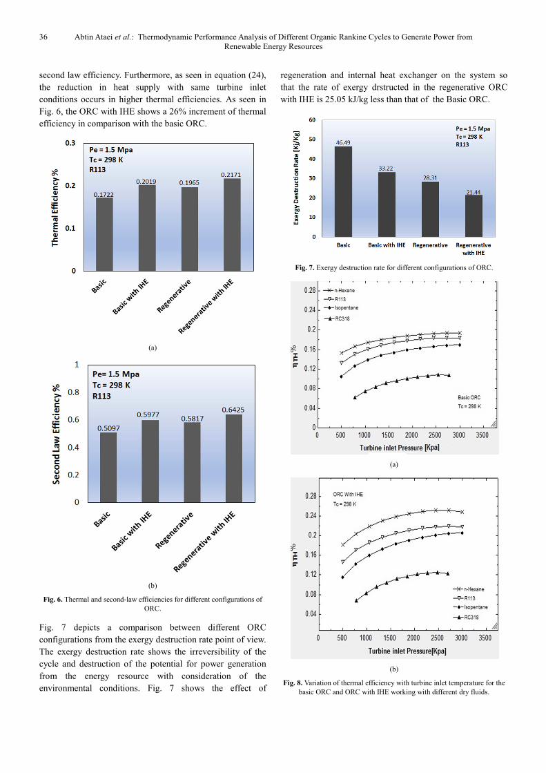
Fig. 7 depicts a comparison between different ORC
configurations from the exergy destruction rate point of view.
The exergy destruction rate shows the irreversibility of the
cycle and destruction of the potential for power generation
from the energy resource with consideration of the
environmental conditions. Fig. 7 shows the effect of
regeneration and internal heat exchanger on the system so
that the rate of exergy drstructed in the regenerative ORC
with IHE is 25.05 kJ/kg less than that of the Basic ORC.
Fig. 7. Exergy destruction rate for different configurations of ORC.
(a)
(b)
Fig. 8. Variation of thermal efficiency with turbine inlet temperature for the
basic ORC and ORC with IHE working with different dry fluids.
American Journal of Economics, Finance and Management Vol. 1, No. 2, 2015, pp. 31-38 37
The second part of the results is about a comparison between
the different organic fluids and relations between their
properties and performance. Fig. 8a and 8b show the
variation of the thermal efficiency of basic ORC and basic
ORC with IHE with the turbine inlet pressure, respectively.
Four organic working fluids including n-hexane, iso-pentane,
RC318 and R113 were considered. The results indicated an
increment in the turbine inlet pressure follows with more heat
supply and more network in the turbine, but the percentage of
the increment in work is more than that of the heat supply. As
a result, the thermal efficiency increased. This Figure also
demonstrates that fluids with a higher boiling point and a
critical temperature show a better performance in ORC's.
Among these fluids, n-hexane has the best performance and
RC318 has the worst. According to Table 2, it can be
concluded that the boiling point and critical temperature of
the organic working fluid have a direct relation with the
system's thermal efficiency.
(a)
(b)
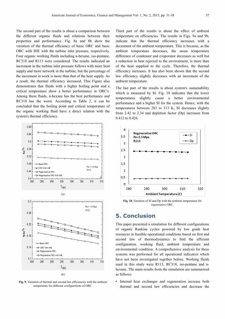
Fig. 9. Variation of thermal and second law efficiencies with the ambient
temperature for different configurations of ORC.
Third part of the results is about the effect of ambient
temperature on efficiencies. The results in Figs. 9a and 9b,
indicate that the thermal efficiency increases with a
decrement of the ambient temperature. This is because, as the
ambient temperature decreases, the mean temperature
difference of condenser and evaporator decreases as well but
a reduction in heat rejected to the environment, is more than
of the heat supplied to the cycle. Therefore, the thermal
efficiency increases. It has also been shown that the second
law efficiency slightly decreases with an increment of the
ambient temperature.
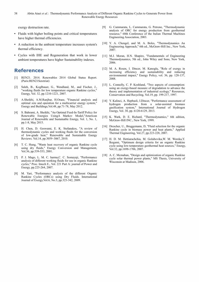
The last part of the results is about system's sustainability
which is measured by SI. Fig. 10 indicates that the lower
temperatures slightly cause a better environmental
performance and a higher SI for the system. Hence, with the
temperatures between 283 to 313 K, SI decreases slightly
from 2.42 to 2.34 and depletion factor (Dp) increases from
0.412 to 0.426.
Fig. 10. Variation of SI and Dp with the ambient temperature for
regenerative ORC.
5. Conclusion
This paper presented a simulation for different configurations
of organic Rankine cycles powered by low grade heat
resources in feasible operational conditions based on first and
second law of thermodynamics to find the efficient
configuration, working fluid, ambient temperature and
environmental condition. A comprehensive analysis for these
systems was performed for all operational indicators which
have not been investigated together before. Working fluids
used in this study were R113, RC318, iso-pentane and n-
hexane. The main results from the simulation are summarized
as follows:
• Internal heat exchanger and regeneration increase both
thermal and second law efficiencies and decrease the
38 Abtin Ataei et al.: Thermodynamic Performance Analysis of Different Organic Rankine Cycles to Generate Power from
Renewable Energy Resources
exergy destruction rate.
• Fluids with higher boiling points and critical temperatures
have higher thermal efficiencies.
• A reduction in the ambient temperature increases system's
thermal efficiency.
• Cycles with IHE and Regeneration that work in lower
ambient temperatures have higher Sustainability indexes.
References
[1] REN21. 2014. Renewables 2014 Global Status Report. (Paris:REN21Seretriat)
[2] Saleh, B., Koglbauer, G., Wendland, M., and Fischer, J., "working fluids for low temperature organic Rankine cycles," Energy, Vol. 32, pp.1210-1221, 2007.
[3] A.Sheikhi, A.M.Ranjbar, H.Oraee, "Financial analysis and optimal size and operation for a multicarrier energy system," Energy and Buildings,Vol.48, pp.71-78, May 2012.
[4] S. Bahrami, A. Sheikhi, "An Optimal Feed-In-Tariff Policy for Renewable Energies UsingA Markov Model,"American Journal of Renewable and Sustainable Energy, Vol. 1, No. 1, pp.1-8, May 2015.
[5] H. Chen, D. Goswami, E. K. Stefanakos, "A review of thermodynamic cycles and working fluids for the conversion of low-grade heat," Renewable and Sustainable Energy Reviews. Vol.14, pp.3059–3067, 2010.
[6] T. C. Hung, "Waste heat recovery of organic Rankine cycle using dry fluids," Energy Conversion and Management, Vol.36, pp.539-553, 2001.
[7] P. J. Mago, L. M. C. harma,C. C. Somayaji, "Performance analysis of different working fluids for use in organic Rankine cycles," Proc. Imech E., Vol. 221 Part A: journal of Power and Energy, pp.225-264, 2007.
[8] M. Yari, "Performance analysis of the different Organic Rankine Cycles (ORCs) using Dry Fluids. International Journal of Exergy,Vol.6, No.3, pp.323-342, 2009.
[9] G. Cammarata, L. Cammarata, G. Petrone, "Thermodynamic analysis of ORC for energy production from geothermal resource," 68th Conference of the Italian Thermal Machines Engineering Association, 2003.
[10] Y. A. Chengel, and M. A. Boles, "Thermodynamics An Engineering Approach," 6th ed., McGraw-Hill Inc., New York, 2007.
[11] M.J. Moran, H.N. Shapiro, "Fundamentals of Engineering Thermodynamics, 5th ed., John Wiley and Sons, New York, 2006.
[12] M. A. Rosen, I. Dincer, M. Kanoglu, "Role of exergy in increasing efficiency and sustainability and reducing environmental impact," Energy Policy, vol. 36, pp. 128-137, 2008.
[13] L. Connelly, C. P. Koshland, "Two aspects of consumption: using an exergy-based measure of degradation to advance the theory and implementation of industrial ecology," Resources, Conservation and Recycling, Vol.19, pp. 199-217, 1997.
[14] Y. Kalinci, A. Hepbasli, I.Dincer, "Performance assessment of hydrogen production from a solar-assisted biomass gasification system," International Journal of Hydrogen Energy, Vol. 38, pp. 6120-6129, 2013.
[15] K. Wark, D. E. Richard, "Thermodynamics," 6th edition, McGraw-Hill INC., New York, 1999.
[16] Drescher, U., Bruggemann, D, "Fluid selection for the organic Rankine cycle in biomass power and heat plants," Applied Thermal Engineering, Vol.27, pp.223-228, 2007.
[17] H. D. M. Hettiarachchia, M. Golubovika,W. M. Woreka,Y. Ikegami, "Optimum design criteria for an organic Rankine cycle using low-temperature geothermal heat sources," Energy, Vol.32, pp.1698-1706, 2007.
[18] A. C. Mcmahan, "Design and optimization of organic Rankine cycle solar thermal power plants," MS Thesis, University of Wisconsin at Madison, 2006.