Embed Size (px)
DESCRIPTION
Introduction to thermodynamics involved in the operation of Internal Combustion Engines
Citation preview
Internal Combustion Engines – General Course Layout
SUBJECT: ME-448 INTERNAL COMBUSTION ENGINES
CREDIT HOURS: 3-0
CONTACT HOURS: 3 Hours per Week
TEXT BOOK:
• Internal Combustion Engines: Applied Thermo sciences, Colin R.Ferguson, Allan T. Kirkpatrick, 2nd Edition, Wiley
REFERENCE BOOKS:
• Edward F. Obert, Internal Combustion Engines and Air Pollution,Harper & Row NewYark.
• Internal Combustion Engines by V.Ganesan
• Internal Combustion Engine by Willard W. Pulkrabek
Classification of I. C. Engines
•Nature of Thermodynamic Cycle 1. Otto cycle engine 2. Diesel cycle engine3. Dual combustion cycle engine
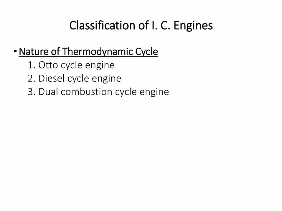
INTAKE [Suction]: During the intake stroke, the piston movesdown ward, drawing a fresh charge of vaporized fuel-airmixture, This operation is represented by the line AB on theP-V diagram.
Volume [V]
Pressure [P]
AB
TDC
BDC
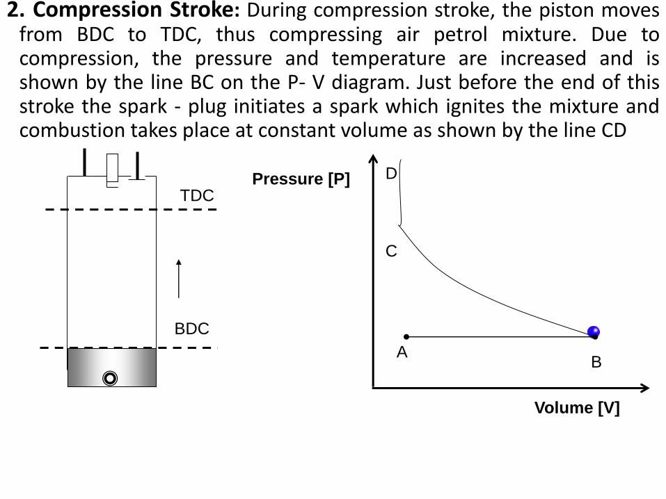
2. Compression Stroke: During compression stroke, the piston movesfrom BDC to TDC, thus compressing air petrol mixture. Due tocompression, the pressure and temperature are increased and isshown by the line BC on the P- V diagram. Just before the end of thisstroke the spark - plug initiates a spark which ignites the mixture andcombustion takes place at constant volume as shown by the line CD
Volume [V]
Pressure [P]
AB
TDC
BDC
C
D
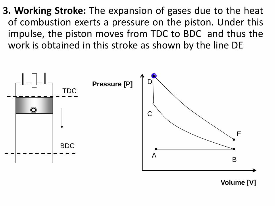
3. Working Stroke: The expansion of gases due to the heatof combustion exerts a pressure on the piston. Under thisimpulse, the piston moves from TDC to BDC and thus thework is obtained in this stroke as shown by the line DE
Volume [V]
Pressure [P]
AB
TDC
BDC
C
D
E
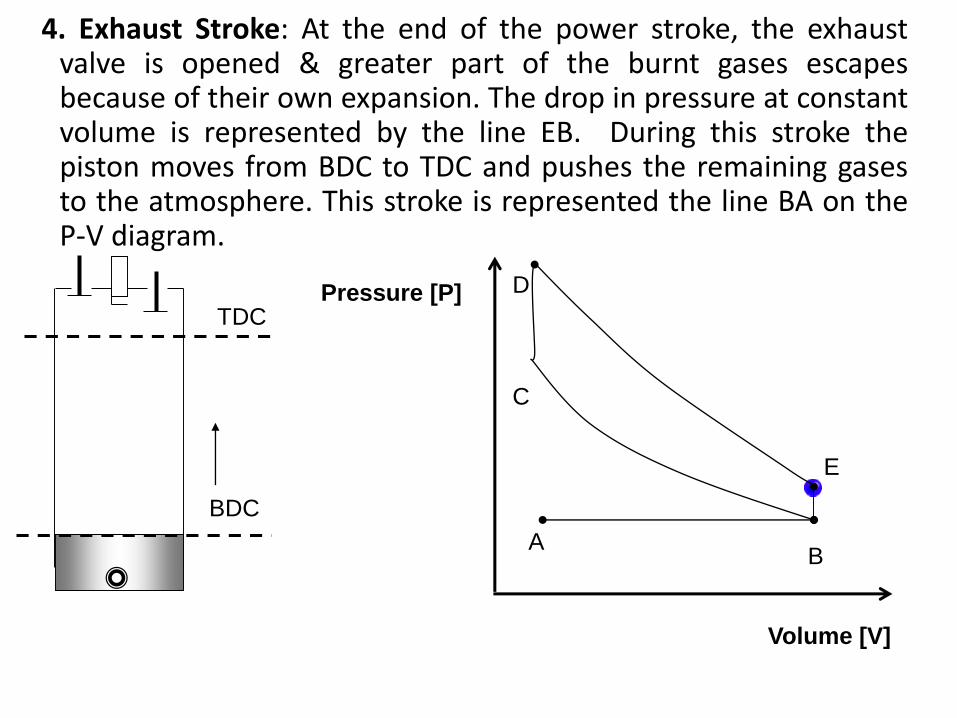
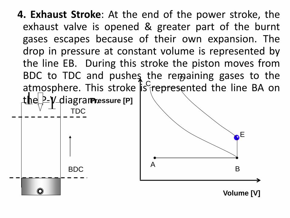
4. Exhaust Stroke: At the end of the power stroke, the exhaustvalve is opened & greater part of the burnt gases escapesbecause of their own expansion. The drop in pressure at constantvolume is represented by the line EB. During this stroke thepiston moves from BDC to TDC and pushes the remaining gasesto the atmosphere. This stroke is represented the line BA on theP-V diagram.
Volume [V]
Pressure [P]
AB
TDC
BDC
C
D
E
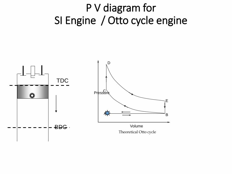
P V diagram for SI Engine / Otto cycle engine
TDC
BDC
C
A B
E
D
Pressure
Volume
Theoretical Otto cycle
Working of 4-S Diesel/CI Engine
The basic construction of a four stroke diesel engine is
same as that of four stroke petrol engine.
Except that instead of a spark plug, a FUEL INJECTOR is
mounted in its space.
Fuel injector injects the fuel in to the cylinder as a fine
spray at very high pressure
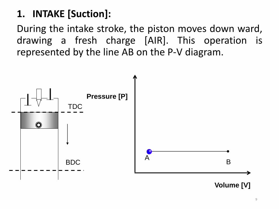
1. INTAKE [Suction]:
During the intake stroke, the piston moves down ward,drawing a fresh charge [AIR]. This operation isrepresented by the line AB on the P-V diagram.
9
TDC
BDC
Volume [V]
Pressure [P]
AB
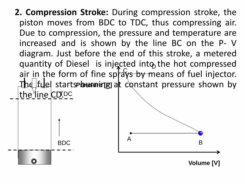
2. Compression Stroke: During compression stroke, thepiston moves from BDC to TDC, thus compressing air.Due to compression, the pressure and temperature areincreased and is shown by the line BC on the P- Vdiagram. Just before the end of this stroke, a meteredquantity of Diesel is injected into the hot compressedair in the form of fine sprays by means of fuel injector.The fuel starts burning at constant pressure shown bythe line CD.TDC
BDC
Volume [V]
Pressure [P]
AB
CD
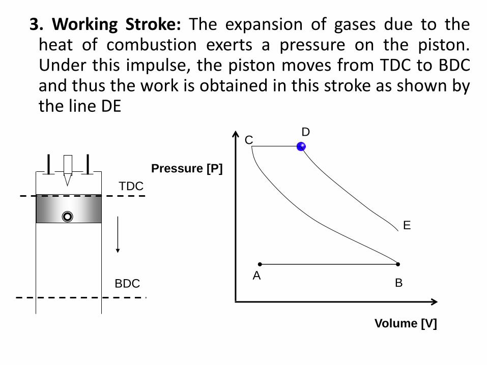
3. Working Stroke: The expansion of gases due to theheat of combustion exerts a pressure on the piston.Under this impulse, the piston moves from TDC to BDCand thus the work is obtained in this stroke as shown bythe line DE
TDC
BDC
Volume [V]
Pressure [P]
AB
CD
E
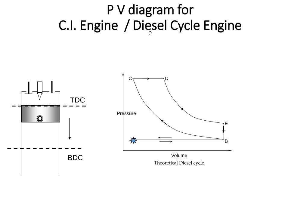
4. Exhaust Stroke: At the end of the power stroke, theexhaust valve is opened & greater part of the burntgases escapes because of their own expansion. Thedrop in pressure at constant volume is represented bythe line EB. During this stroke the piston moves fromBDC to TDC and pushes the remaining gases to theatmosphere. This stroke is represented the line BA onthe P-V diagram.
TDC
BDC
Volume [V]
Pressure [P]
AB
CD
E
C
A B
E
D
Pressure
Volume
Theoretical Diesel cycle
P V diagram for C.I. Engine / Diesel Cycle Engine
D
TDC
BDC
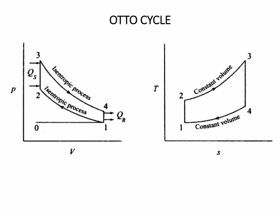
OTTO CYCLE
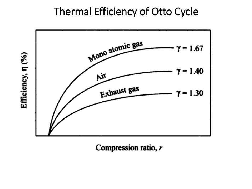
Thermal Efficiency of Otto Cycle
There is heat supplied and heat rejected and bothprocesses are occurring at constant volume.
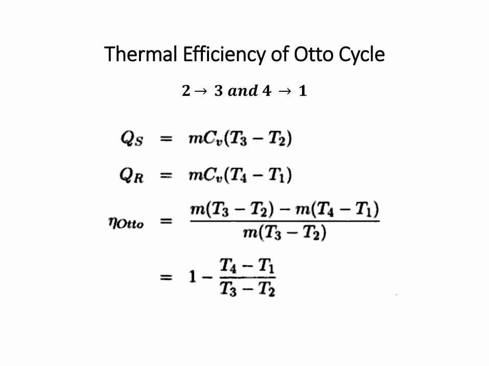
Thermal Efficiency of Otto Cycle
𝟐 𝟑 𝒂𝒏𝒅 𝟒 𝟏
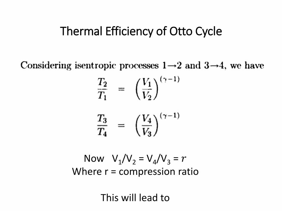
Thermal Efficiency of Otto Cycle
Now V1/V2 = V4/V3 = 𝑟Where r = compression ratio
This will lead to
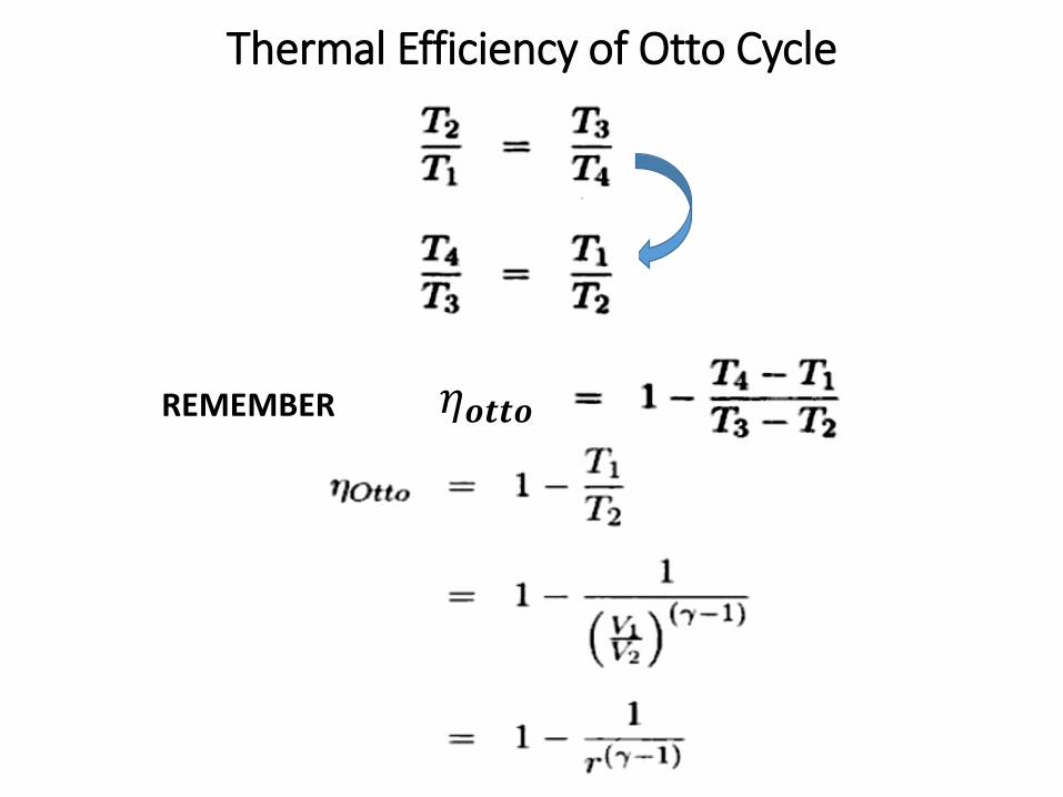
Thermal Efficiency of Otto Cycle
𝜂𝒐𝒕𝒕𝒐REMEMBER
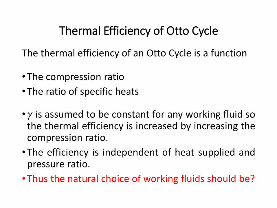
Thermal Efficiency of Otto Cycle
The thermal efficiency of an Otto Cycle is a function
•The compression ratio
•The ratio of specific heats
•𝛾 is assumed to be constant for any working fluid sothe thermal efficiency is increased by increasing thecompression ratio.
•The efficiency is independent of heat supplied andpressure ratio.
•Thus the natural choice of working fluids should be?
Thermal Efficiency of Otto Cycle
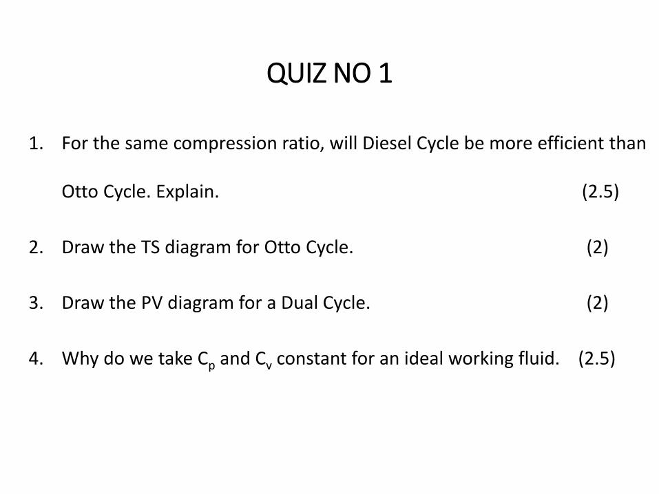
QUIZ NO 1
1. For the same compression ratio, will Diesel Cycle be more efficient than
Otto Cycle. Explain. (2.5)
2. Draw the TS diagram for Otto Cycle. (2)
3. Draw the PV diagram for a Dual Cycle. (2)
4. Why do we take Cp and Cv constant for an ideal working fluid. (2.5)
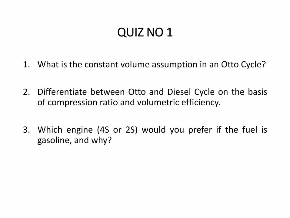
QUIZ NO 1
1. What is the constant volume assumption in an Otto Cycle?
2. Differentiate between Otto and Diesel Cycle on the basisof compression ratio and volumetric efficiency.
3. Which engine (4S or 2S) would you prefer if the fuel isgasoline, and why?
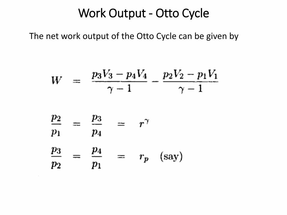
Work Output - Otto Cycle
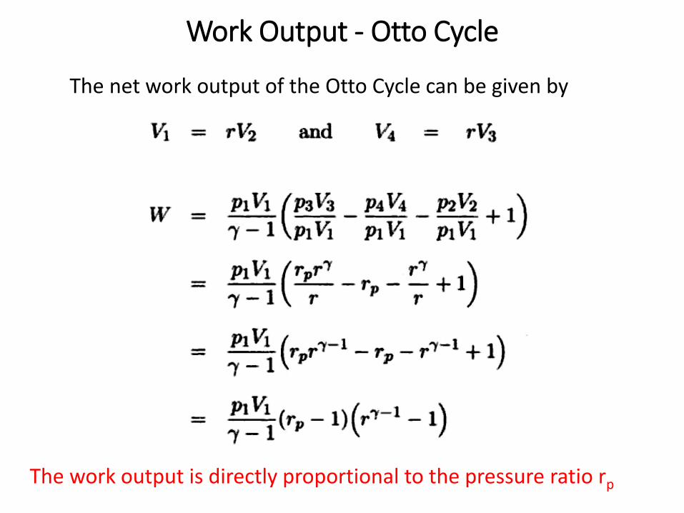
The net work output of the Otto Cycle can be given by
Work Output - Otto Cycle
The net work output of the Otto Cycle can be given by
The work output is directly proportional to the pressure ratio rp
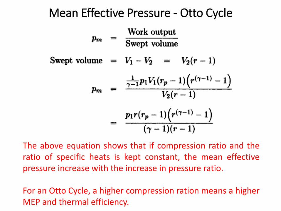
Mean Effective Pressure - Otto Cycle
The above equation shows that if compression ratio and theratio of specific heats is kept constant, the mean effectivepressure increase with the increase in pressure ratio.
For an Otto Cycle, a higher compression ration means a higherMEP and thermal efficiency.
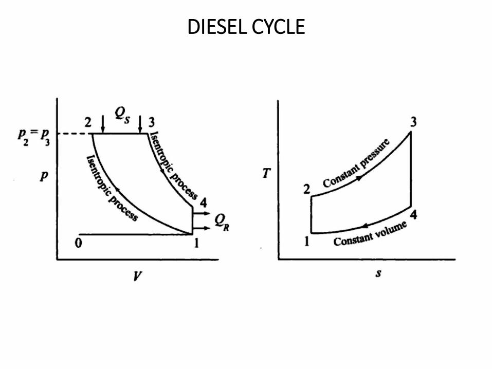
DIESEL CYCLE
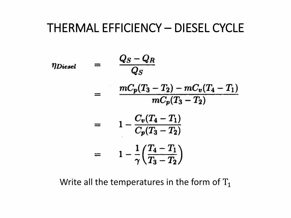
THERMAL EFFICIENCY – DIESEL CYCLE
Write all the temperatures in the form of T1
THERMAL EFFICIENCY – DIESEL CYCLE
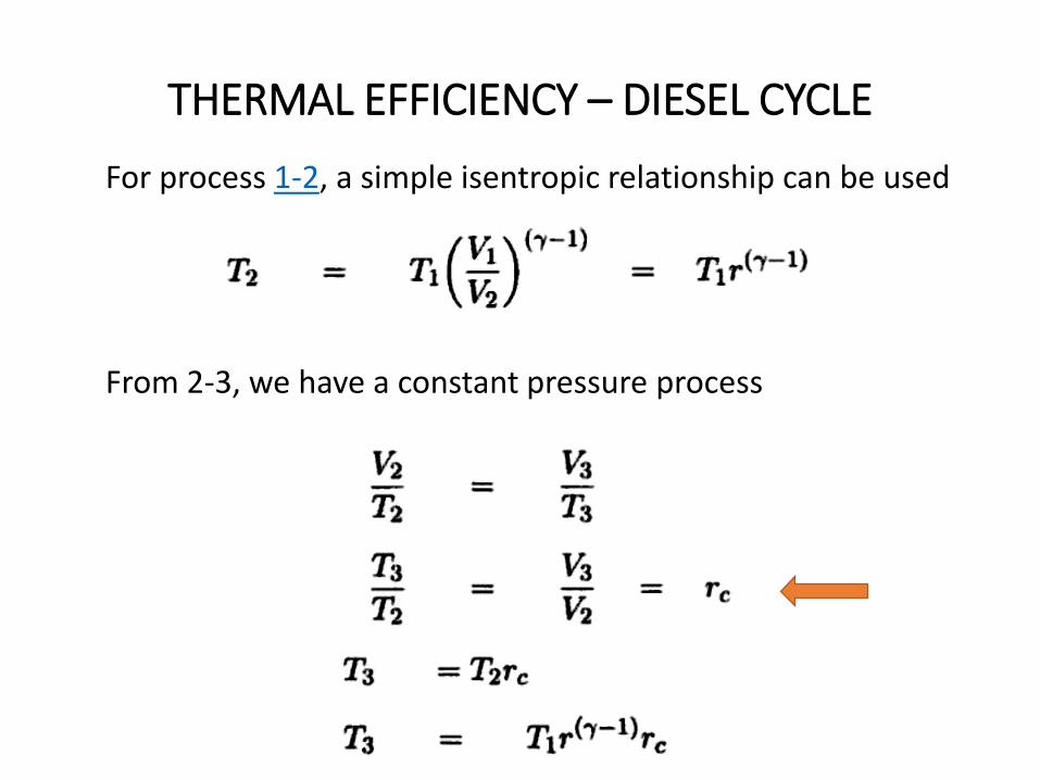
For process 1-2, a simple isentropic relationship can be used
From 2-3, we have a constant pressure process
THERMAL EFFICIENCY – DIESEL CYCLE
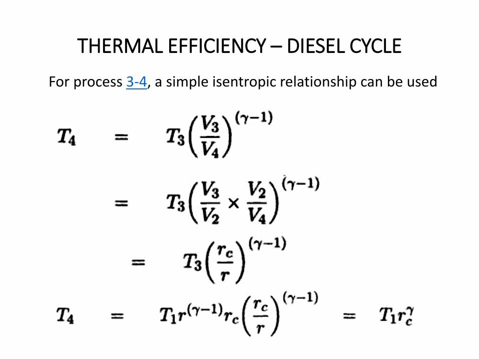
For process 3-4, a simple isentropic relationship can be used
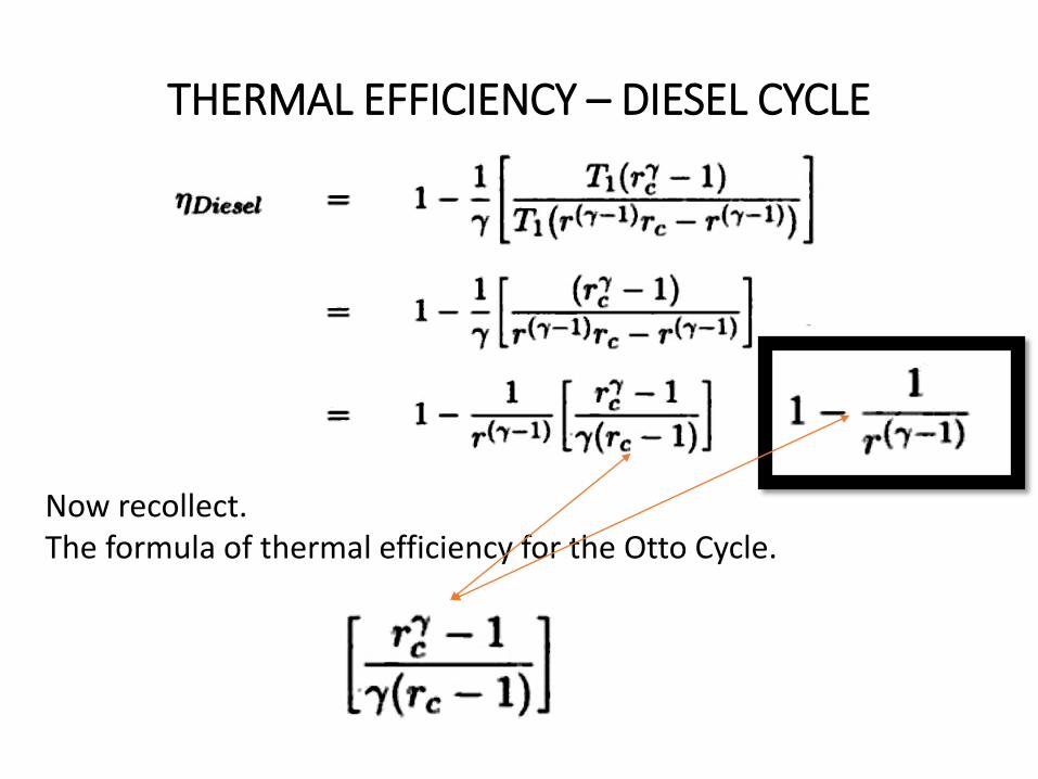
THERMAL EFFICIENCY – DIESEL CYCLE
Now recollect. The formula of thermal efficiency for the Otto Cycle.

THERMAL EFFICIENCY – DIESEL CYCLE
• Let call the factor in last slide as factor A.
• We can tell that factor A will always have a value greater than
unity.
• Hence for a given compression ratio, Otto cycle will always will
be more efficient than Diesel cycle. (True/False ????)
• rc depends on output and is maximum at maximum output (?)
• Thus diesel engine efficiency depends on output (what about
Otto cycle?).
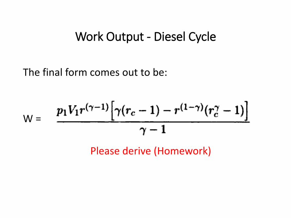
Work Output - Diesel Cycle
The final form comes out to be:
W =
Please derive (Homework)
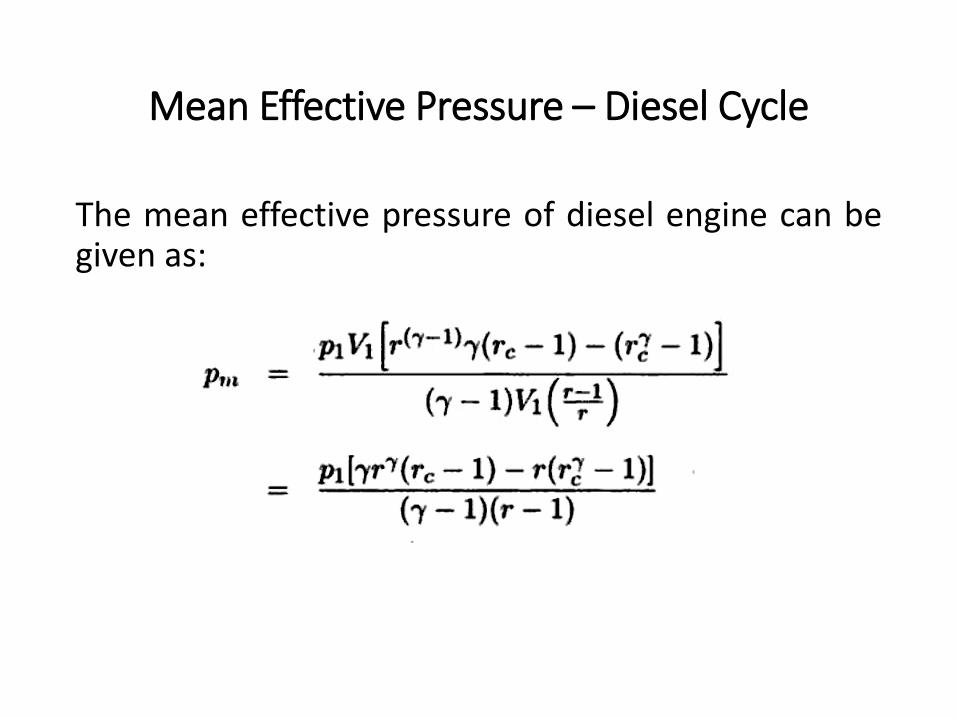
Mean Effective Pressure – Diesel Cycle
The mean effective pressure of diesel engine can begiven as:
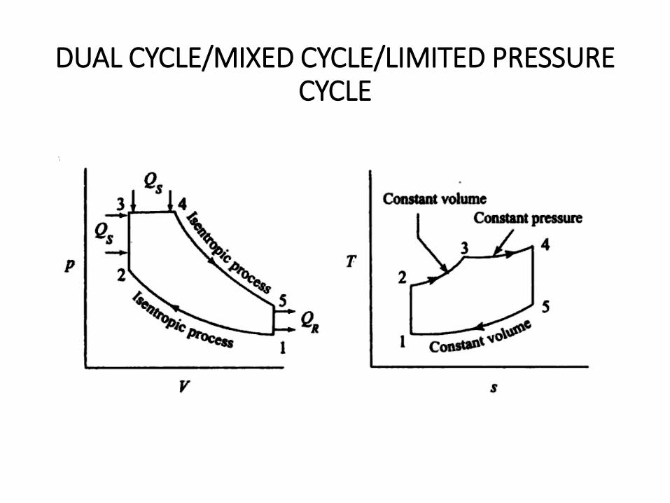
DUAL CYCLE/MIXED CYCLE/LIMITED PRESSURE CYCLE
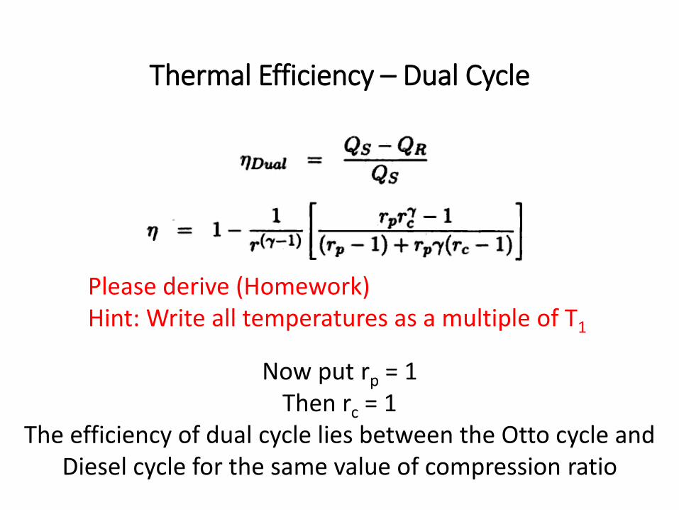
Thermal Efficiency – Dual Cycle
Please derive (Homework)Hint: Write all temperatures as a multiple of T1
Now put rp = 1Then rc = 1
The efficiency of dual cycle lies between the Otto cycle and Diesel cycle for the same value of compression ratio
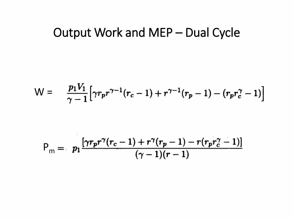
Output Work and MEP – Dual Cycle
W =
Pm
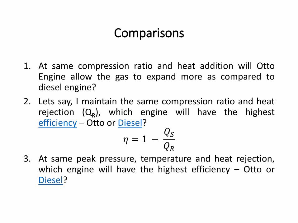
Comparisons
1. At same compression ratio and heat addition will OttoEngine allow the gas to expand more as compared todiesel engine?
2. Lets say, I maintain the same compression ratio and heatrejection (QR), which engine will have the highestefficiency – Otto or Diesel?
𝜂 = 1 −𝑄𝑆𝑄𝑅
3. At same peak pressure, temperature and heat rejection,which engine will have the highest efficiency – Otto orDiesel?
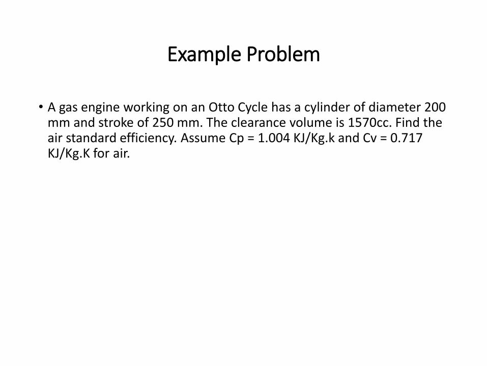
Example Problem
• A gas engine working on an Otto Cycle has a cylinder of diameter 200 mm and stroke of 250 mm. The clearance volume is 1570cc. Find the air standard efficiency. Assume Cp = 1.004 KJ/Kg.k and Cv = 0.717 KJ/Kg.K for air.
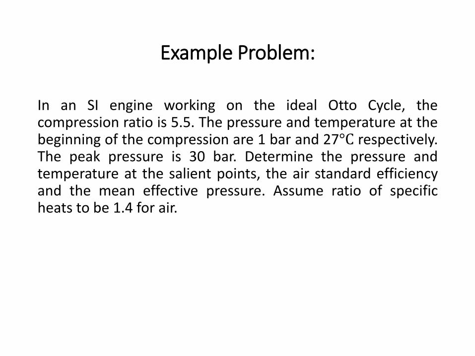
Example Problem:
In an SI engine working on the ideal Otto Cycle, thecompression ratio is 5.5. The pressure and temperature at thebeginning of the compression are 1 bar and 27°C respectively.The peak pressure is 30 bar. Determine the pressure andtemperature at the salient points, the air standard efficiencyand the mean effective pressure. Assume ratio of specificheats to be 1.4 for air.