Embed Size (px)
Citation preview

MATEC Web of Conferences 14, 10002 (2014)DOI: 10.1051/matecconf/20141410002c© Owned by the authors, published by EDP Sciences, 2014
Thermomechanical behavior of different Ni-base superalloys duringcyclic loading at elevated temperatures
Daniel Huber1,a, Matthias Hacksteiner2,3, Cecilia Poletti2, Fernando Warchomicka2, and Martin Stockinger1
1 Bohler Schmiedetechnik GmbH & Co KG, Kapfenberg, Austria2 Institute of Materials Science and Welding, Graz University of Technology, Austria3 Institute for Production Engineering and Laser Technology, Vienna University of Technology, Austria
Abstract. The material behavior of three Ni-base superalloys (Inconel R© 718, Allvac R© 718PlusTM andHaynes R© 282 R©) during in-phase cyclic mechanical and thermal loading was investigated. Stress controlledthermo-mechanical tests were carried out at temperatures above 700 ◦C and different levels of maximumcompressive stress using a Gleeble R© 3800 testing system. Microstructure investigations via light opticalmicroscopy (LOM) and field emission gun scanning electron microscopy (FEG-SEM) as well as numericalprecipitation kinetics simulations were performed to interpret the obtained results. For all alloys, the predominantdeformation mechanism during deformation up to low plastic strains was identified as dislocation creep. Themain softening mechanism causing progressive increase of plastic strain after preceding linear behavior issuggested to be recrystallization facilitated by coarsening of grain boundary precipitates. Furthermore, coarseningand partial transformation of strengthening phases was observed. At all stress levels, Haynes R© 282 R© showedbest performance which is attributable to its stable microstructure containing a high phase fraction of small,intermetallic precipitates inside grains and different carbides evenly distributed along grain boundaries.
1. IntroductionA strong demand for higher efficiency, reduced fuelconsumption, CO2 and NOx emissions as well as weightreduction in aircraft engines lead to a substitution ofpresently used materials by novel light-weight, hightemperature materials like γ -TiAl alloys. Hot-working ofTiAl alloys, however, is a complex and challenging taskdue to a small processing window. Isothermal forging, asstate of the art process, uses Mo-based die material towithstand high processing temperatures.
Bohler Schmiedetechnik GmbH & Co KG hasdeveloped a hot-die forging process with die temperaturesabove 700 ◦C. These temperatures necessitate the use ofhigh temperature resistance materials as die material [1].In order to produce sound forgings in an economicprocess, following requirements arise for the die material:temperature resistance and microstructural stability attemperatures above 700 ◦C, low thermal expansion, goodmachinability, good weldability and oxidation resistanceat operation temperature. Literature study and companyexperience favored three different alloys: (the Ni-basesuperalloy working horse) Inconel R© 718, ATI’s Allvac R©718PlusTM and Haynes R© 282 R©.
Aim of the present work was to compare theapplicability of the three Ni-base superalloys as promisingdie material for TiAl turbine blade hot-die forging.
a Corresponding author: [email protected]
2. Experimental
2.1. Materials and heat treatment
2.2. Inconel R© 718
Double melt (VIM + VAR) Inconel R© 718 materialwith a billet size of round 5” (127 mm) was used. Thechemical composition in wt.% from heat lot analysis isshown in Table 1. The billet was solution annealed at1010 ◦C for 1 hour with subsequent air cooling. Thetemperature was chosen to solubilize a high amount ofNb and simultaneously retaining a certain amount of grainboundary stabilizing δ phase. This Nb in the matrix favorsthe precipitation of a high amount of γ ′′ phase duringaging. Single step aging was performed at 788 ◦C for6 hours, followed by air cooling [2]. Final grain size variedbetween 60 µm and 140 µm and an average γ ′′ volumephase fraction of 14% was measured from image analysis.The disk-shaped precipitates showed a characteristic sizeof 70 ± 15 nm and an aspect ratio of 0.35 ± 0.1. Plate-likeδ phase was found along grain boundaries, as shown inFig. 1.
To verify results from microstructural analysis, nu-merical precipitation kinetics simulations were performedby use of the software package c©MatCalc. Results forInconel R© 718 after full heat treatment are shown in Fig. 2.
Calculated volume fraction of γ ′′ was 12.2% with amean diameter of 85 nm and a volume fraction of 1.3%δ with a particle diameter of 392 nm. Additionally, 3.8%
This is an Open Access article distributed under the terms of the Creative Commons Attribution License 4.0, which permits unrestricted use, distribution,and reproduction in any medium, provided the original work is properly cited.
Article available at http://www.matec-conferences.org or http://dx.doi.org/10.1051/matecconf/20141410002

MATEC Web of Conferences
Table 1. Chemical composition of the three alloys.
Co Cr Fe Mo W
Inconel R© 718 0.15 19.32 17.50 2.99 –
Allvac R© 718PlusTM 9.16 17.92 9.34 2.69 1.0
Haynes R© 282 R© 10.38 19.45 0.79 8.52 –
Al Ti Nb C Ni
Inconel R© 718 0.49 0.95 5.20 0.02 bal.
Allvac R© 718PlusTM 1.51 0.75 5.50 0.02 bal.
Haynes R© 282 R© 1.57 2.13 – 0.06 bal.
Figure 1. FEG-SEM image of undeformed Inconel R© 718.
of γ ′ with a diameter of 36 nm was calculated although itcould not be detected in FEG-SEM.
2.2.1. Allvac R© 718PlusTM
Triple melt (VIM + ESR + VAR) Allvac R© 718PlusTM
with a billet size of round 8” (203.2 mm) was used. Thechemical composition in wt.% from heat lot analysis issummarized in Table 1. The bar was solution annealed at968 ◦C for one hour and air cooled, followed by two-stepaging (788 ◦C for 8 hours, furnace cooling with 56 ◦C/hand 704 ◦C for 8 hours), as suggested by W.D. Cao,et al. [3], to obtain about 4% δ phase for grain boundarystabilization. A final grain size between 45 µm and 55 µmand a γ ′ volume phase fraction of 16% was achieved. Thespherical γ ′ precipitates showed a diameter of 80 ± 15 nm(see Fig. 3). These results are in good correlation withc©MatCalc simulations, which predicted 16.4% volume
fraction of γ ′ with a mean diameter of 76nm and 3.3%volume fraction of δ with a diameter of 422 nm.
2.2.2. Haynes R© 282
Double melt (VIM + VAR) Haynes R© 282 R© with a billetsize of round corned square 12” (304.8 mm) was used. Thechemical composition in wt.% from heat lot analysis is
Figure 2. Results from c©MatCalc precipitation kineticssimulations for Inconel R© 718.
Figure 3. FEG-SEM image of undeformed Allvac R© 718PlusTM.
shown in Table 1. The bar was heat treated at 1010 ◦Cfor 2 hours with subsequent air cooling followed by8 hours annealing at 788 ◦C, as proposed by L. Pike [4].A final grain size between 150 µm and 180 µm and aγ ′ volume phase fraction of 18% were measured. Thespherical precipitates had a mean diameter of 35 ± 5 nm.Figure 4a shows the distribution of γ ′ particles insidea grain and Fig. 4b is a detailed illustration of grainboundary carbides. c©MatCalc calculations predicted avolume fraction of 18.4% γ ′ with a mean diameter of28 nm. Carbides were identified as M6C and M23C6 withM being Cr, Ni, Mo [5].
2.3. Sample preparation
Cylindrical Gleeble R© tensile samples were machined outof the heat treated billets according to Fig. 5. Except forInconel R© 718 specimens, the main axis of the machinedspecimen was perpendicular to the longitudinal axis of barmaterial. For Inconel R© 718 samples, the specimen axiswas parallel to the longitudinal axis. Cylindrical sampleswere cut out of the bars via wire-cut electrical discharge
10002-p.2

EUROSUPERALLOYS 2014
Figure 4. FEG-SEM image of undeformed Haynes R© 282 R©.
Figure 5. Tensile sample for physical forging simulation.
machining. Finally, threads were machined on the samplesand the small burr from electrical discharge machining wasremoved by use of grinding paper.
For temperature control, type K thermocouples(NiCr-Ni) were used because of their low cost andgood weldability to Ni-base alloy specimens. The twothermocouple wires with a diameter of 0.2 mm werespot-welded on the specimens’ center, perpendicular totheir main axis 1 mm apart from each other using a DSIThermocouple Welder 35200.
2.4. Gleeble R© 3800 testing setup
All thermo-mechanical tests were performed on a DSIGleeble R© 3800 testing system. The device contains aresistance heating system for heating rates of up to10000 ◦C/s. Samples can be quenched with air, inert gas orwater. The hydraulic servo system is capable of exertingstatic forces of up to 98 kN in tension and 196 kN incompression with a maximum speed of 2000 mm/s.
The physical forging simulations were carried out withparameters related to mechanical and thermal loads duringreal forging processes. For that, real temperature andstress profiles were obtained from finite element forgingsimulations done in the software package Deform3DTM.
Figure 6. Maximum temperature (left) and stress (right)distribution in the lower die during forging.
Figure 7. Setup of experiments at the Gleeble R© 3800.
A cross section through the highest loaded part of the dieis shown in Fig. 6.
Based on results from numerical simulation, threemaximum mechanical compression stresses were definedas −450 MPa, −350 MPa and −300 MPa.
The tensile specimens were fixed in axial directionfor physical forging simulation. Therefore, a two-stageclamping process was utilized. First, the specimen wasclamped in tensile direction pneumatically via copper jawsand locking nuts followed by clamping in compressivedirection via counterpieces (shims, setscrews and nuts) onboth sides. The setup is illustrated in Fig. 7.
Specimen stress and strain were determined preciselythroughout the thermo-mechanical tests. An air cooledEpsilon diametral extensometer (C-Gauge) was usedto measure the specimen diameter in situ. Gleeble R©3800 physical forging simulations were performedstress controlled using the true stress signal from theextensometer. The relationship between diameter and truestress follows Eq. (1).
σ =F
A=
4F
π (d0 + �d)2 · (1)
where σ is true stress, F is force, A stands for area, d0 isthe initial diameter and � d is the change in diameter.
Resulting thermal stresses (σtherm) due to thermalexpansion and contraction during heating and cooling,respectively, were calculated according to Eq. (2) andverified in calibration tests.
σtherm = − Eα�T . (2)
10002-p.3
MATEC Web of Conferences
Figure 8. Temperature cycle used for calibration measurements.
Figure 9. Thermal and mechanical load cycles used in physicalforging simulations.
Table 2. Comparison of testing cycles up to a total plastic strainof 0.1 for each alloy and maximum mechanical stress level.
Allvac R© Haynes R©Inconel R© 718 718PlusTM 282 R©
−450 MPa 1 ± 0.5 10 ± 1 80 ± 30
−350 MPa 10 ± 3 50 ± 10 480 ± 80
−300 MPa 40 ± 10 160 ± 50 1230 ± 110
σtherm is the stress resulting from a change in temperature,E stands for Young’s Modulus and � T is the temperaturedifference. Total stress (σtot) applied to the test specimenis consequently the sum of mechanical stress (σmech) andσtherm (see Eq. (3)),
σ = σtot = σmech + σtherm. (3)
A schematic diagram of the calibration tests is depicted inFig. 8.
To simulate a real TiAl turbine blade forging process,the tests consisted of following sequences:
• heating up from room temperature to Tdie (1st run)• holding at Tdie• heating up from Tdie to Tmax – applying stress σtot• holding at Tmax
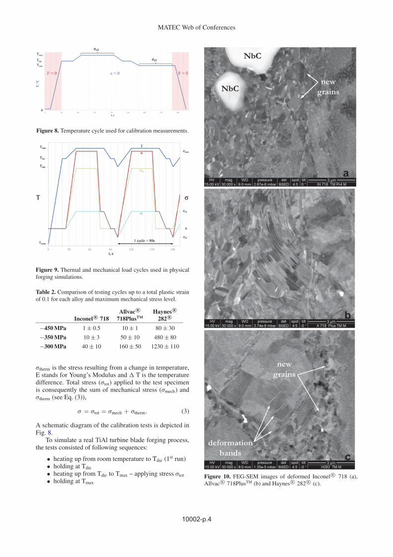
Figure 10. FEG-SEM images of deformed Inconel R© 718 (a),Allvac R© 718PlusTM (b) and Haynes R© 282 R© (c).
10002-p.4

EUROSUPERALLOYS 2014
Table 3. Minimum strain rate of the three alloys during physical forging simulation.
Allvac R© Haynes R©Inconel R© 718 718PlusTM 282 R©
−450 MPa (−2.0 ± 0.6) · 10−3 (−1.2 ± 0.3) · 10−4 (−1.3 ± 0.4) · 10−5
−350 MPa (−1.2 ± 0.1) · 10−4 (−2.5 ± 0.4) · 10−5 (−1.1 ± 0.5) · 10−6
−300 MPa (−3.2 ± 0.7) · 10−5 (−7.5 ± 1.8) · 10−6 (−5.2 ± 1.0) · 10−7
• removal of applied stress σmech• cooling from Tmax to Tdie – removal of σtherm• holding at Tdie• cooling from Tdie to Tmin – applying σtherm• holding of Tmin• heating up to Tdie – removal of σtherm.
Tdie is the die temperature during forging (above 700 ◦C),Tmax is the maximum temperature (about 90 ◦C aboveTdie) at the die surface during a forging cycle and Tminis the minimum surface temperature (about 70 ◦C belowTdie) due to cleaning of the die with compressed air. Aschematic overview of the temperature and stress sequenceis illustrated in Fig. 9.
3. Results and discussion
Main performance criterion for die material was defined asservice time (denoted by testing cycles) until a maximumplastic strain of 0.1 was reached.
Table 2 summarizes the resulting number of cycles foreach alloy.
To better interpret results from physical simulations,deformed microstructures were investigated by use oflight optical microscopy and field emission gun scanningelectron microscopy. For each alloy, a non-linear strainafter preceding linear behavior at low strains was observed,similar to the tertiary and secondary creep stages describedin literature. In this non-linear strain dependency oftime, the main softening mechanism was identified tobe the formation of new grains via recrystallization(see Fig. 10). These new grains are more or less freeof precipitates. Specifically, coarsening of γ ′′ phaseand partial transformation to δ phase was observed forInconel R© 718. The γ ′ phase partly transformed to δ
phase in Allvac R© 718PlusTM, which is in good correlationwith [6]. Haynes R© 282 R© showed no transformations,but slight coarsening of γ ′. From microstructural pointof view, it can be concluded, that the outstandingperformance of Haynes R© 282 R© compared to the othertwo alloys is based on the stability and morphology ofgrain boundary carbides which delay recrystallization.Furthermore, the high amount of γ ′ phase and its highthermal stability favor the application of Haynes R© 282 R©as die material.
To determine the dominating hot deformation mecha-nism, the stress exponent (n) for each alloy in the linear lowstrain region of the obtained strain curves was evaluated.A simplified creep approach was used neglecting varyingtemperature and stress during thermo-mechanical testsand assuming no microstructural changes during the early
Figure 11. Stress dependence of minimum strain rates duringphysical forging simulations.
Figure 12. Stress dependence of minimum strain rates correctedby threshold stress.
stages of deformation (see Eq. (4)).
εmin = Kσ n,
log ε = log K + n log σ (4)
The minimum strain rate εmin for each alloy is shown inTable 3.
According to Eq. (4) the stress exponent can be foundas inclination of a minimum strain rate vs. testing stressplot (see Fig. 11).
However, results of this simplified assumption do notcorrelate to real testing results. The approach was refinedby adding threshold stress σth into Eq. (4). This stress isneeded to detach dislocations from precipitates and is oftenassumed to be proportional to the Orowan stress. Usingmaterial parameters at maximum testing temperature andmaximum compression stress, σth can be calculated by useof Eq. (5) [7].
σth = 0.06 Mτ0 ln
√8
3
d
b(5)
10002-p.5

MATEC Web of Conferences
where M is the Taylor factor, τ0 is Orowan stress, dthe mean particle diameter and b the Burger’s vector.Combining Eqs. (4) and (5) leads to Eq. (6)
εmin = K (σ − σth)n. (6)
Threshold stresses σth for Inconel R© 718, Allvac R©718PlusTM and Haynes R© 282 R© were calculated to be100 MPa, 110 MPa and 200 MPa, respectively.
Linear plots of minimum strain rates vs. testing stressesconsidering threshold stresses are depicted in Fig. 12.
Considering the correction by σth, the derived stressexponent values for Inconel R© 718, Allvac R© 718PlusTM
and Haynes R© 282 R© are 7.2, 4.6 and 3.5, respectively.While n values around 4 are typically related todeformation mechanism dislocation creep, the n valuefor Inconel R© 718 is still too high after correction.An explanation could be the fact, that γ ′ phase wasnot observed experimentally and therefore neglected inthreshold stress calculation.
ConclusionPhysical forging simulations on a Gleeble R© 3800 testingsystem were conducted to evaluate three different Ni-base superalloys for application as die material in ahot-die forging process of TiAl turbine blades. Basedon numerical simulation, temperature and compressionstress profiles were defined. A maximum plastic strainof 0.1 was set as performance criterion. The number oftesting cycles showed large differences in temperature
stability of all three alloys. Subsequent microstructureanalyses showed changes in precipitation distribution andmorphology as well as recrystallization. The dominatingdeformation mechanism was identified as dislocation creepby determining stress exponents for all three alloys. Fromthe results discussed above, it can be concluded thatthe better performance of Haynes R© 282 R©, under testedconditions and compared to the other two alloys, is basedon the stability and distribution of grain boundary carbideswhich retard softening by recrystallization.
The present work was financially conducted within theframework of the CleanSky initiative of the EuropeanCommission in project DAFNE (Grant Agreement No 278084).Authors would like to thank USTEM (Vienna University ofTechnology) for the FEG-SEM facilities.
References
[1] D. Huber, M. Stockinger, H. Clemens, 2012 MRS FallMeeting, 1516, 23, (2012)
[2] R.B. Bhavsar, A. Collins, S. Silverman, Superalloys718, 625, 706, and Various Derivatives, 47, (2001)
[3] W.D. Cao, R.L. Kennedy, Recommendations for Heattreating Allvac R© 718Plus R© Alloy Parts, (2006)
[4] L.M. Pike, Superalloys 2008, 191, (2008)[5] F. Duschel, Master Thesis, (2013)[6] W.D. Cao, Superalloys 718, 625, 706, and Various
Derivatives, 165, (2005)[7] I. Holzer, PhD Thesis, (2010)
10002-p.6
![Segregation-Assisted Plasticity in Ni-Based Superalloys...2017/11/13 · Ni-based superalloys[7,8]—because of the presence of a significant fraction of the c0-phase of ordered](https://img.pdfslide.net/doc/110x75/613d87e4e1ef621e9f2dc7e4/segregation-assisted-plasticity-in-ni-based-superalloys-20171113-ni-based.jpg)