Embed Size (px)
Citation preview
Lecture # 16 Thermomechanical Conversion II
Two-Phase Cycles and Combined Cycles
Ahmed Ghoniem April 1, 2020
Rankine Cycle: two phase regionSuperheat and Ultra-superheat Cycles. Reheating. Recuperation.Supercritical Cycles. Hypercritical Cycles (CO2 as working fluid) Water requirements.
© Ahmed F. Ghoniem 1
250
0
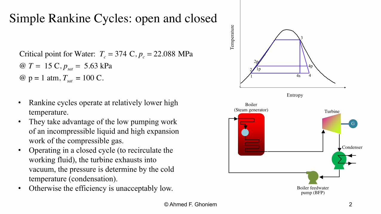
Simple Rankine Cycles: open and closed
Critical point for Water: Tc = 374 C, pc = 22.088 MPa @ T = 15 C, psat = 5.63 kPa @ p = 1 atm, Tsat = 100 C.
Temperature
Entropy
1 2
3
4s 1p
4
4p 2p
• Rankine cycles operate at relatively lower high Boiler (Steam generator)temperature. Turbine
• They take advantage of the low pumping work of an incompressible liquid and high expansion work of the compressible gas.
• Operating in a closed cycle (to recirculate the working fluid), the turbine exhausts into vacuum, the pressure is determine by the cold temperature (condensation).
Condenser
G
• Otherwise the efficiency is unacceptably low. Boiler feedwater pump (BFP)
© Ahmed F. Ghoniem 2

Simple ideal Rankine Cycle: Simple saturated cycle efficiency,
wpump,ideal = h2 s − h1 = v( p2 − p1 ) Pressure Ratio = 8,Pump = 65%, turbine 90%.
wT ,ideal = h3 − h4 s
qH = h3 − h2
wT − wpump ηI = qH
In a real cycle: v( p2 − p1 )=wpump ηis
wT = ηT ,is (h3 − h4 s ) qH = h3 − h2
Conventional Tmin=20 Closed cycle
Pmin=1atm Open cycle
wpump(kJ/kg)
1.23 1.12
wt(kJ/kg)
736 316
wnet(kJ/kg)
735 315
η 27.4 % 13.4%
ηideal 30.4% 14.9% ηcar 33.9% 15.8% X4 0.794 0.8856
© Ahmed F. Ghoniem 3
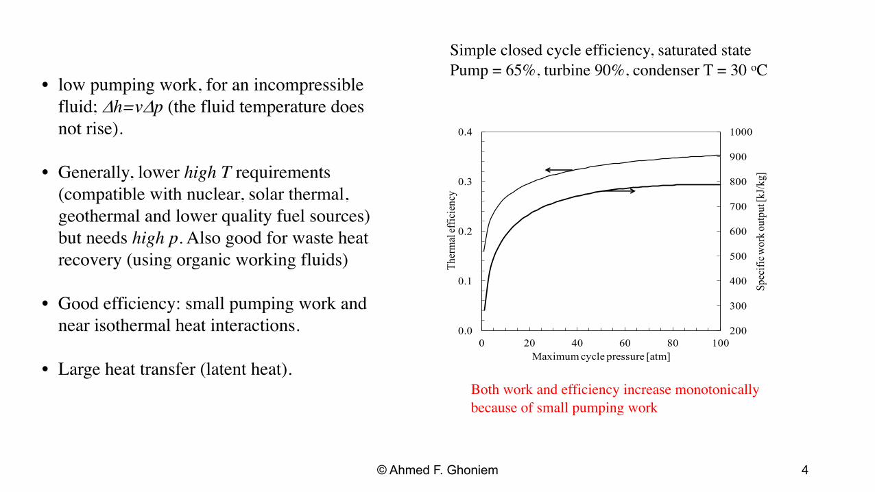
Simple closed cycle efficiency, saturated statePump = 65%, turbine 90%, condenser T = 30 oC
• low pumping work, for an incompressiblefluid; Dh=vDp (the fluid temperature does not rise). 0.4 1000
0.0
900
• Generally, lower high T requirements(compatible with nuclear, solar thermal,
0.3
Spec
ific w
ork o
utpu
t [kJ
/kg]
800
Ther
mal
effic
ienc
y
700geothermal and lower quality fuel sources)but needs high p. Also good for waste heatrecovery (using organic working fluids)
0.2 600
500
0.1 400
• Good efficiency: small pumping work and 300
near isothermal heat interactions. 200 0 20 40 60 80 100
Maximum cycle pressure [atm] • Large heat transfer (latent heat).
Both work and efficiency increase monotonically because of small pumping work
© Ahmed F. Ghoniem 4
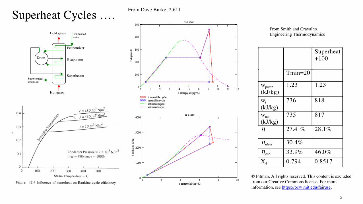
From Dave Burke, 2.611 Superheat Cycles …. Cold gases Condensed
water
Economizer
Evaporator
SuperheaterSuperheated steam out
Drum
Hot gases
From Smith and Cravalho, Engineering Thermodynamics
Superheat+100
Tmin=20
wpump(kJ/kg)
1.23 1.23
wt(kJ/kg)
736 818
wnet(kJ/kg)
735 817
η 27.4 % 28.1%
ηideal 30.4% ηcar 33.9% 46.0% X4 0.794 0.8517
© Pitman. All rights reserved. This content is excluded from our Creative Commons license. For more information, see https://ocw.mit.edu/fairuse.
5
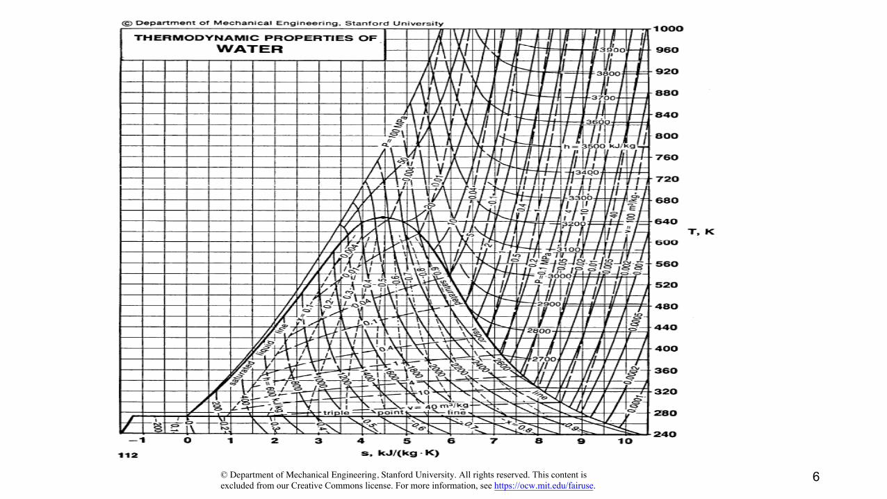
© Department of Mechanical Engineering, Stanford University. All rights reserved. This content is excluded from our Creative Commons license. For more information, see https://ocw.mit.edu/fairuse.
6
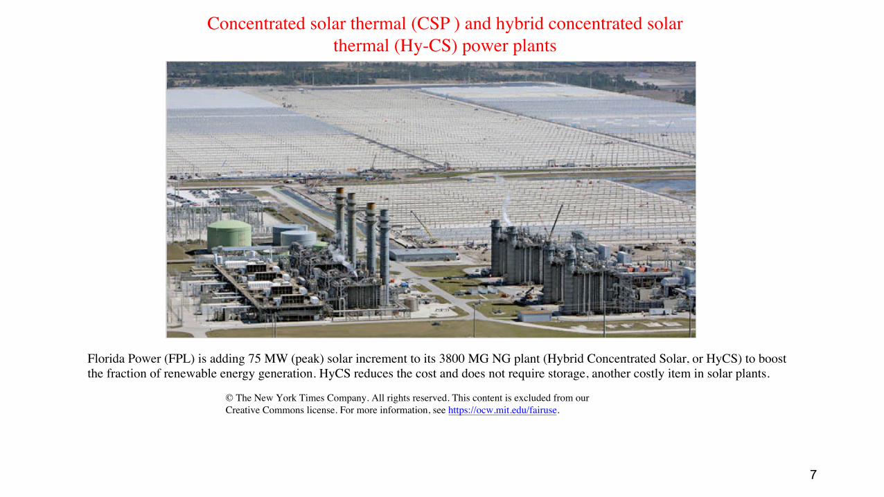
Concentrated solar thermal (CSP ) and hybrid concentrated solarthermal (Hy-CS) power plants
Florida Power (FPL) is adding 75 MW (peak) solar increment to its 3800 MG NG plant (Hybrid Concentrated Solar, or HyCS) to boostthe fraction of renewable energy generation. HyCS reduces the cost and does not require storage, another costly item in solar plants.
© The New York Times Company. All rights reserved. This content is excluded from our Creative Commons license. For more information, see https://ocw.mit.edu/fairuse.
7
From reheat 5
HP
Reheat Cycle 3
To Reheat 4
6
GLP
2
3
4
5
61 2
1
850
800
750
700
650
600
550
500
450
400
350
300
250 0 1 2 3 4 5 6 7 8 9 10
Entropy [kJ/kg.K]
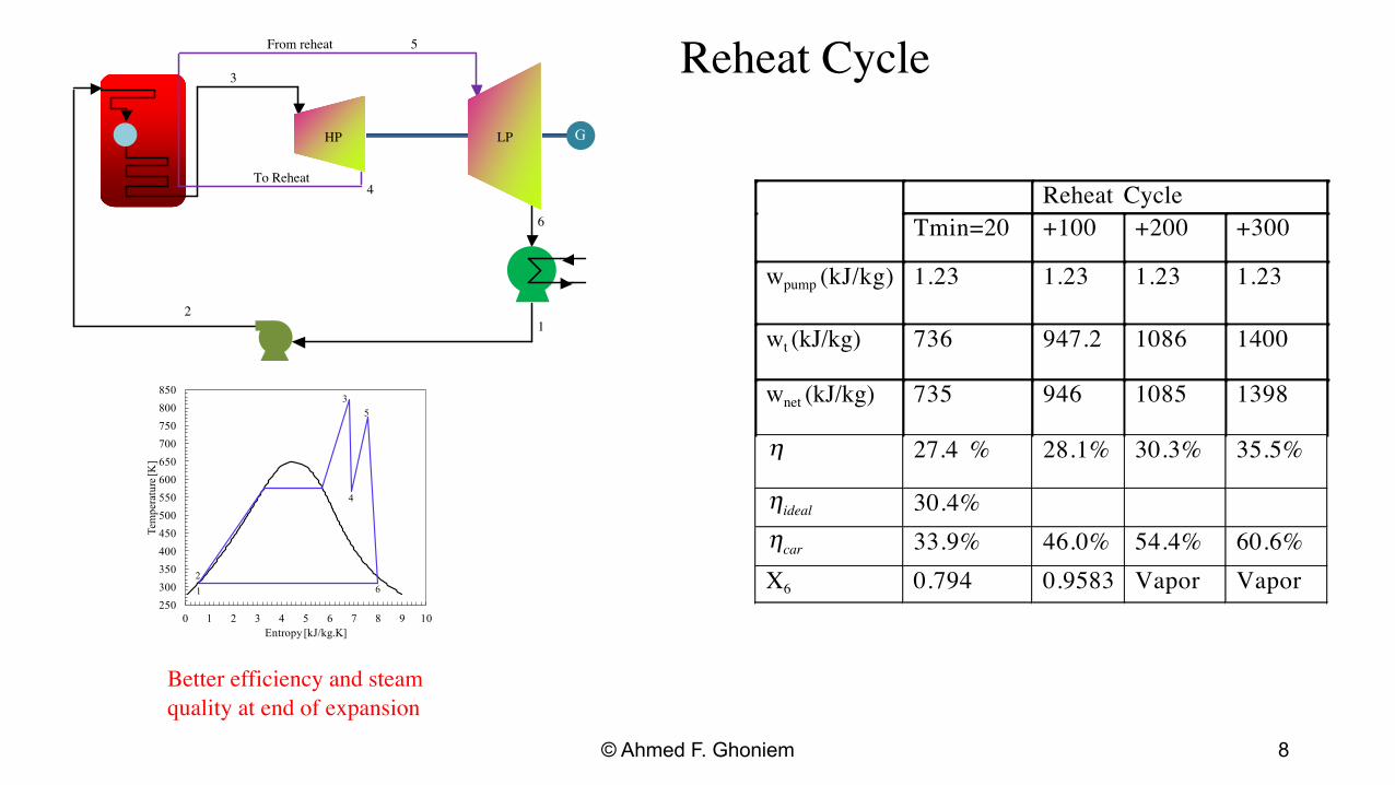
Reheat Cycle Tmin=20 +100 +200 +300
(kJ/kg)wpump 1.23 1.23 1.23 1.23
wt (kJ/kg) 736 947.2 1086 1400
wnet (kJ/kg) 735 946 1085 1398
η 27.4 % 28.1% 30.3% 35.5%
ηideal 30.4% ηcar 33.9% 46.0% 54.4% 60.6% X6 0.794 0.9583 Vapor Vapor
Tem
pera
ture
[K]
Better efficiency and steamquality at end of expansion
© Ahmed F. Ghoniem 8

is
i
Technical Data
SIEMENS SST-500
© Siemens. All rights reserved. This content is excluded from our Creative Commons license. For more information, see https://ocw.mit.edu/fairuse.
All data are approximate and project-related Typical plant layout for a SST-500
Output range up to 85 MW Steam Turbine live steam conditions temperature up to 540C / 1000F Dimensions pressure up to 140 bar / 2000 ps Length (L) 10m/32.8 ft. to 19m/62.3 ft. Bleed up to 2 at various pressure level
Width (W) 4.0m/13.1 ft. to 6.0m/19.7 ft. Controlled extraction Height (H) 3.5m/11.5 ft. to 5.0m/16.5 ft temperature up to 350C / 662F
pressure up to 30 bar / 435 ps
© Ahmed F. Ghoniem 9
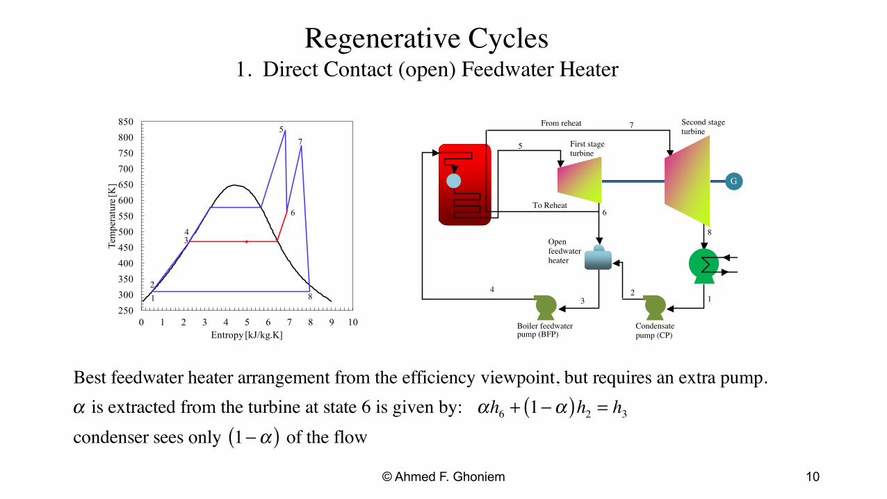
Regenerative Cycles 1. Direct Contact (open) Feedwater Heater
Tem
pera
ture
[K]
850
800
750
700
650
600
550
500
450
400
350
300
250
5
6
7
81 2
3 4
0 1 2 3 4 5 6 7 8 9 10 Entropy [kJ/kg.K]
From reheat Second stage7 turbine
8 Openfeedwater heater
4
First stageturbine
To Reheat
5
6
G
2 13
Boiler feedwater Condensate pump (BFP) pump (CP)
Best feedwater heater arrangement from the efficiency viewpoint, but requires an extra pump. α is extracted from the turbine at state 6 is given by: αh6 + (1 −α )h2 = h3
condenser sees only (1 −α ) of the flow
© Ahmed F. Ghoniem 10
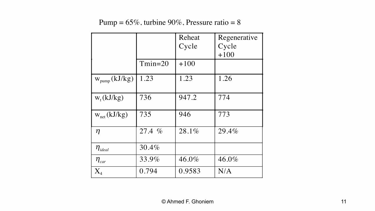
Pump = 65%, turbine 90%, Pressure ratio = 8
Reheat Cycle
RegenerativeCycle+100
Tmin=20 +100
(kJ/kg)wpump 1.23 1.23 1.26
wt (kJ/kg) 736 947.2 774
wnet (kJ/kg) 735 946 773
η 27.4 % 28.1% 29.4%
ηideal 30.4% ηcar 33.9% 46.0% 46.0% X4 0.794 0.9583 N/A
© Ahmed F. Ghoniem 11
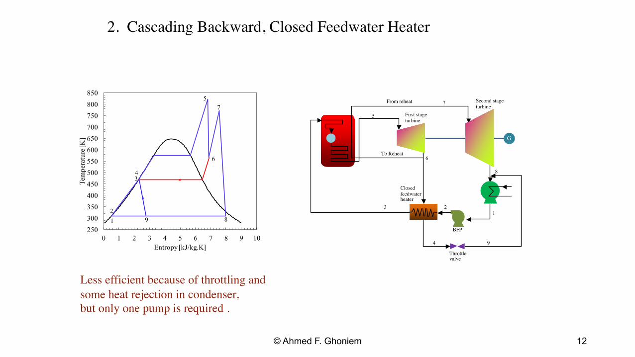
2. Cascading Backward, Closed Feedwater Heater
850 From reheat Second stage7800 turbine
750
700
650
600
550
500
450
400
350 3 1
300
250
2
BFP
0 1 2 3 4 5 6 7 8 9 10 4 9
Entropy [kJ/kg.K] Throttle valve
Less efficient because of throttling and some heat rejection in condenser, but only one pump is required .
5
6
7
81 2
3 4
9
Closed feedwater heater
First stageturbine
To Reheat
5
6
8
G
Tem
pera
ture
[K]
© Ahmed F. Ghoniem 12
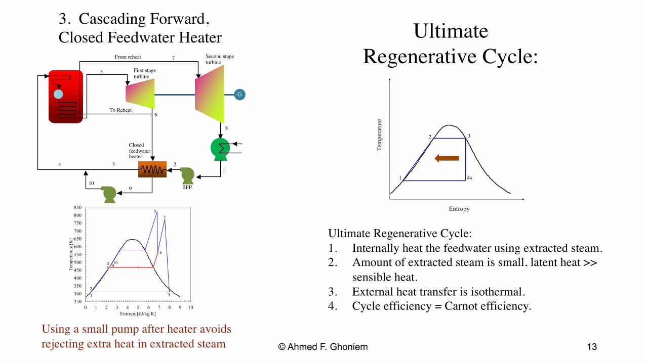
3. Cascading Forward,Closed Feedwater Heater Ultimate
Regenerative Cycle: From reheat Second stage7
Closed feedwater heater
First stageturbine
turbine
To Reheat
1 34
5
6
8
G
Temperature
1
2 3
4s
2
10
2500
BFP9
250
300
350
400
450
500
550
600
650
700
750
800
850 5
6
7
81 2
3 4 9
10
Ultimate Regenerative Cycle:1.
Entropy
Tem
pera
ture
[K]
Internally heat the feedwater using extracted steam.2. Amount of extracted steam is small, latent heat >>
sensible heat. 3. External heat transfer is isothermal.
0 1 2 3 4 5 6 7 8 9 10 4. Cycle efficiency = Carnot efficiency. Entropy [kJ/kg.K]
Using a small pump after heater avoidsrejecting extra heat in extracted steam © Ahmed F. Ghoniem 13
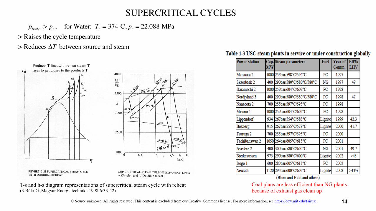
SUPERCRITICAL CYCLES pboiler > pc , for Water: Tc = 374 C, pc = 22.088 MPa
> Raises the cycle temperature > Reduces ΔT between source and steam
Products T line, with reheat steam Trises to get closer to the products T
T-s and h-s diagram representations of supercritical steam cycle with reheat Coal plans are less efficient than NG plants(3.Büki G.,Magyar Energiatechnika 1998;6:33-42) because of exhaust gas clean up
© Source unknown. All rights reserved. This content is excluded from our Creative Commons license. For more information, see https://ocw.mit.edu/fairuse. 14
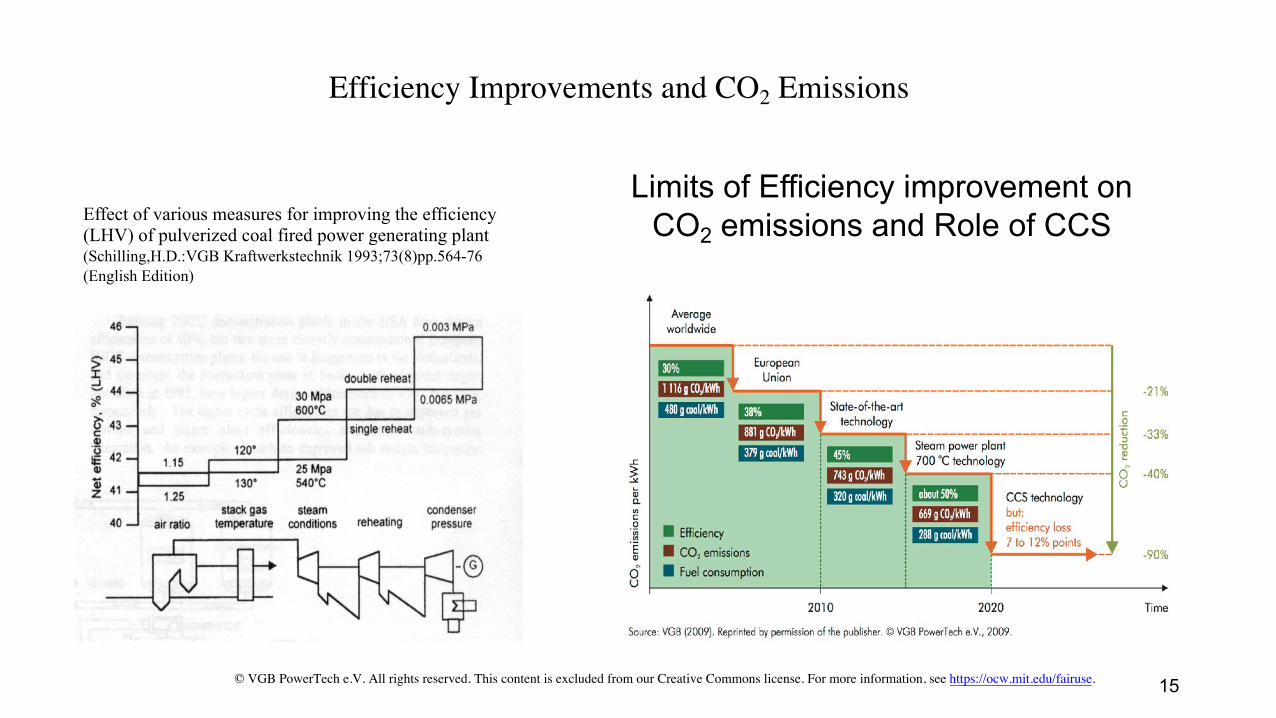
Efficiency Improvements and CO2 Emissions
Limits of Efficiency improvement on Effect of various measures for improving the efficiency (LHV) of pulverized coal fired power generating plant CO2 emissions and Role of CCS (Schilling,H.D.:VGB Kraftwerkstechnik 1993;73(8)pp.564-76 (English Edition)
© VGB PowerTech e.V. All rights reserved. This content is excluded from our Creative Commons license. For more information, see https://ocw.mit.edu/fairuse. 15

Hypercritical closed CO2 �Gas� Cycles
• pcrit = 7.39 MPa, and Tcrit = 30.4 C.• Can take advantage of benefits of
supercritical cycles without the need forvery high p (typical pressure ratio is 4but can go up to 10)).
• High T is used to improve efficiency.• Regeneration improves the efficiency
significantly, see diagrams.• Low compression work (near critical
point, more pumping than compression)• Under consideration for nuclear plants.• Also for oxy-combustion cycles
From Gottlicher, the Energetics of Carbon Sequestration in Power Plants 16
Courtesy of USGS.
© Department of Mechanical Engineering, Stanford University. All rights reserved. This content is
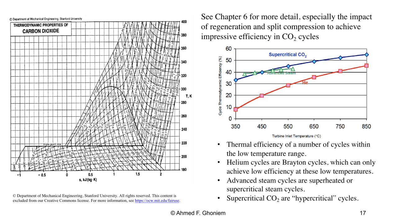
See Chapter 6 for more detail, especially the impactof regeneration and split compression to achieve impressive efficiency in CO2 cycles
• Thermal efficiency of a number of cycles withinthe low temperature range.
• Helium cycles are Brayton cycles, which can onlyachieve low efficiency at these low temperatures.
• Advanced steam cycles are superheated orsupercritical steam cycles.
excluded from our Creative Commons license. For more information, see https://ocw.mit.edu/fairuse. • Supercritical CO2 are “hypercritical” cycles.
© Ahmed F. Ghoniem 17
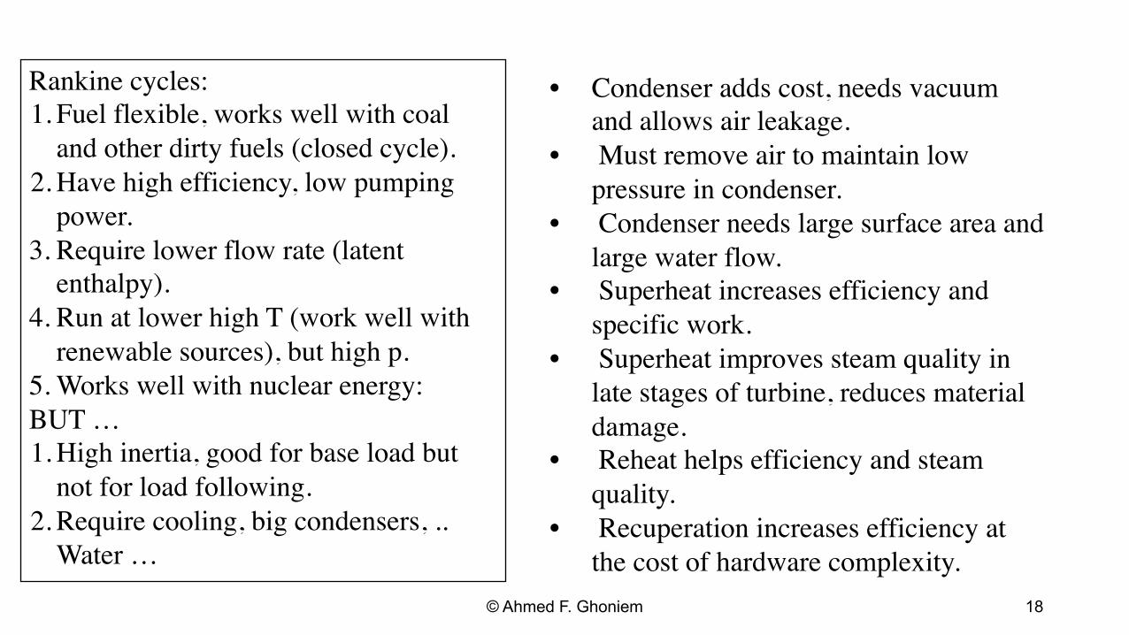
Rankine cycles:1. Fuel flexible, works well with coal
and other dirty fuels (closed cycle).2. Have high efficiency, low pumping
power.3. Require lower flow rate (latent
enthalpy).4. Run at lower high T (work well with
renewable sources), but high p.5. Works well with nuclear energy:BUT … 1. High inertia, good for base load but
not for load following.2. Require cooling, big condensers, ..
Water …
• Condenser adds cost, needs vacuumand allows air leakage.
• Must remove air to maintain low pressure in condenser.
• Condenser needs large surface area andlarge water flow.
• Superheat increases efficiency andspecific work.
• Superheat improves steam quality inlate stages of turbine, reduces materialdamage.
• Reheat helps efficiency and steamquality.
• Recuperation increases efficiency atthe cost of hardware complexity.
© Ahmed F. Ghoniem 18

COMBINED CYCLES
Qin = QGT , WGT = ηGT QGT , QST ≈ (1−ηGT )QGT ,
WST = ηST (1−ηGT )QGT
W = WGT + WST , ηCC = ηGT + ηST (1−ηGT )
ηGT = 0.25, and ηST = 0.4, ηGT = 0.3, and ηST = 0.28, ηGT = 0.38, and ηST = 0.25, ηGT = 0.38, and ηST = 0.40,
Tem
pera
ture
[K]
Fuel 1600
0 1 2 3 4 5 6 7 8 9 10
8
96 7
1
2
3
4
5Steam Cycle
Gas Cycle
7'
8'
9'
3 1400 2
1200
1000
800
GT
1 4 Combustion products
Air 600 8
400
200
Entropy [kJ/kg.K] 9!
ηCC = 0.55
ST
5 7
ηCC = 0.5 6
ηCC = 0.535 ηCC = 0.628
© Ahmed F. Ghoniem 19

Mass flow rates are not arbitrary, Pinch-point analysis and impact on efficiency:
T4 is determined by gas turbine exit conditions T13 is determined by steam cycle high pressure T11 = T13 + PP for good heat transfer rates: PP = O (10 − 15 C) T9 is determined by steam cycle design
cpg (T4 − T11 ) Therefore: m st = m g (h9 − h13 )
© Ahmed F. Ghoniem 20
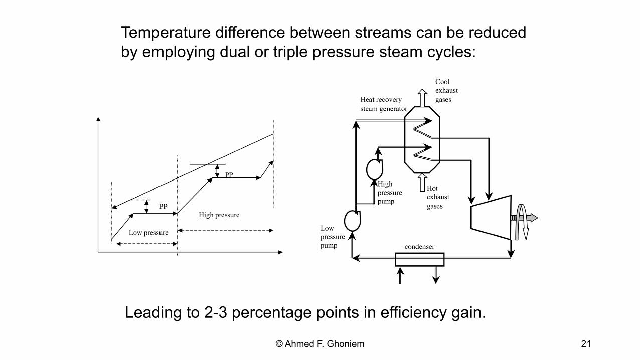
Temperature difference between streams can be reduced by employing dual or triple pressure steam cycles:
Leading to 2-3 percentage points in efficiency gain.
© Ahmed F. Ghoniem 21
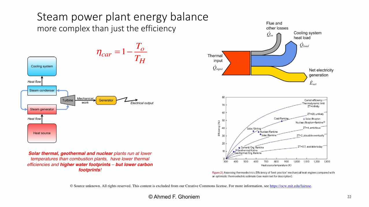
Steam power plant energy balance more complex than just the efficiency
Toηcar =1− TH
Solar thermal, geothermal and nuclear plants run at lower temperatures than combustion plants, have lower thermal
efficiencies and higher water footprints – but lower carbon footprints!
© Source unknown. All rights reserved. This content is excluded from our Creative Commons license. For more information, see https://ocw.mit.edu/fairuse.
© Ahmed F. Ghoniem 22

Cooling system types and tradeoffs
Once-through cooling, withdrawal Dry cooling
All of these •also depend on local water
and weather conditions!
Wet tower cooling, consumption
exit T is the dew point of waterat its partial p in the exit air.
23
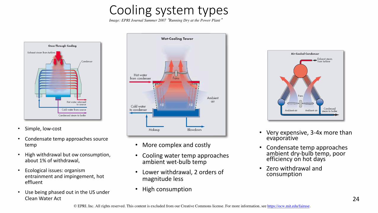
Cooling system typesImage: EPRI Journal Summer 2007 �Running Dry at the Power Plant�
• Simple, low-cost
• Condensate temp approaches source temp
• High withdrawal but ow consumption,about 1% of withdrawal,
• Ecological issues: organismentrainment and impingement, hoteffluent
• Use being phased out in the US under Clean Water Act
• More complex and costly • Cooling water temp approaches
ambient wet-bulb temp • Lower withdrawal, 2 orders of
magnitude less • High consumption
• Very expensive, 3-4x more thanevaporative
• Condensate temp approachesambient dry-bulb temp, poorefficiency on hot days
• Zero withdrawal and consumption
© EPRI, Inc. All rights reserved. This content is excluded from our Creative Commons license. For more information, see https://ocw.mit.edu/fairuse. 24
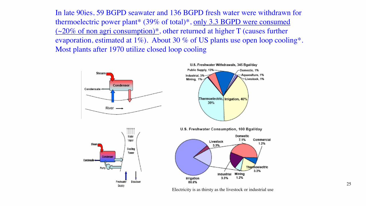
In late 90ies, 59 BGPD seawater and 136 BGPD fresh water were withdrawn forthermoelectric power plant* (39% of total)*, only 3.3 BGPD were consumed (~20% of non agri consumption)*, other returned at higher T (causes further evaporation, estimated at 1%). About 30 % of US plants use open loop cooling*. Most plants after 1970 utilize closed loop cooling
Electricity is as thirsty as the livestock or industrial use 25
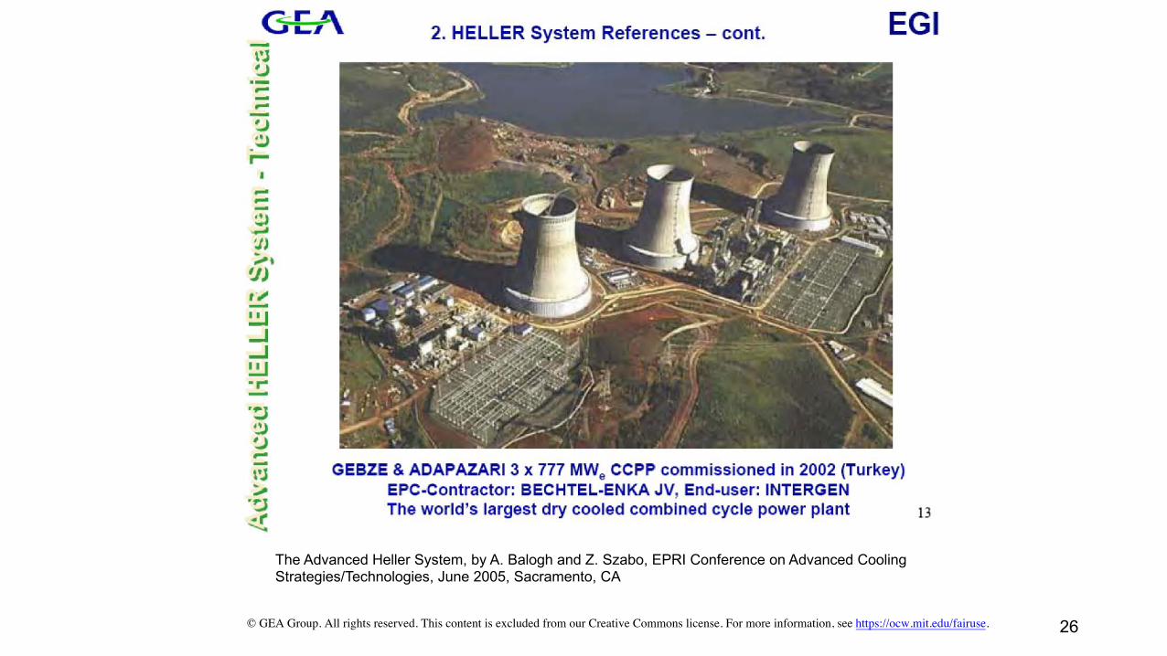
The Advanced Heller System, by A. Balogh and Z. Szabo, EPRI Conference on Advanced Cooling Strategies/Technologies, June 2005, Sacramento, CA
© GEA Group. All rights reserved. This content is excluded from our Creative Commons license. For more information, see https://ocw.mit.edu/fairuse. 26
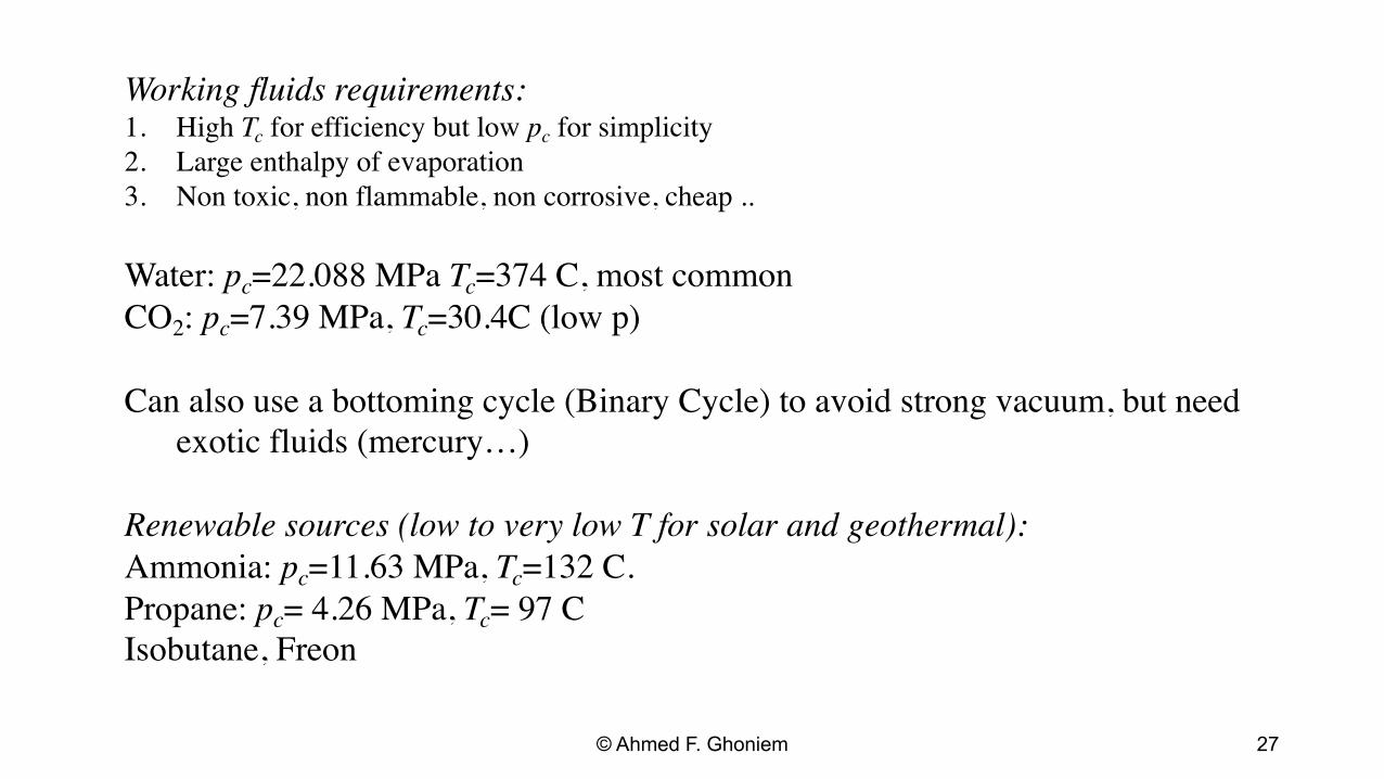
Working fluids requirements:1. High Tc for efficiency but low pc for simplicity 2. Large enthalpy of evaporation 3. Non toxic, non flammable, non corrosive, cheap ..
Water: pc=22.088 MPa Tc=374 C, most common CO2: pc=7.39 MPa, Tc=30.4C (low p)
Can also use a bottoming cycle (Binary Cycle) to avoid strong vacuum, but need exotic fluids (mercury…)
Renewable sources (low to very low T for solar and geothermal):Ammonia: pc=11.63 MPa, Tc=132 C. Propane: pc = 4.26 MPa, Tc = 97 C Isobutane, Freon
© Ahmed F. Ghoniem 27
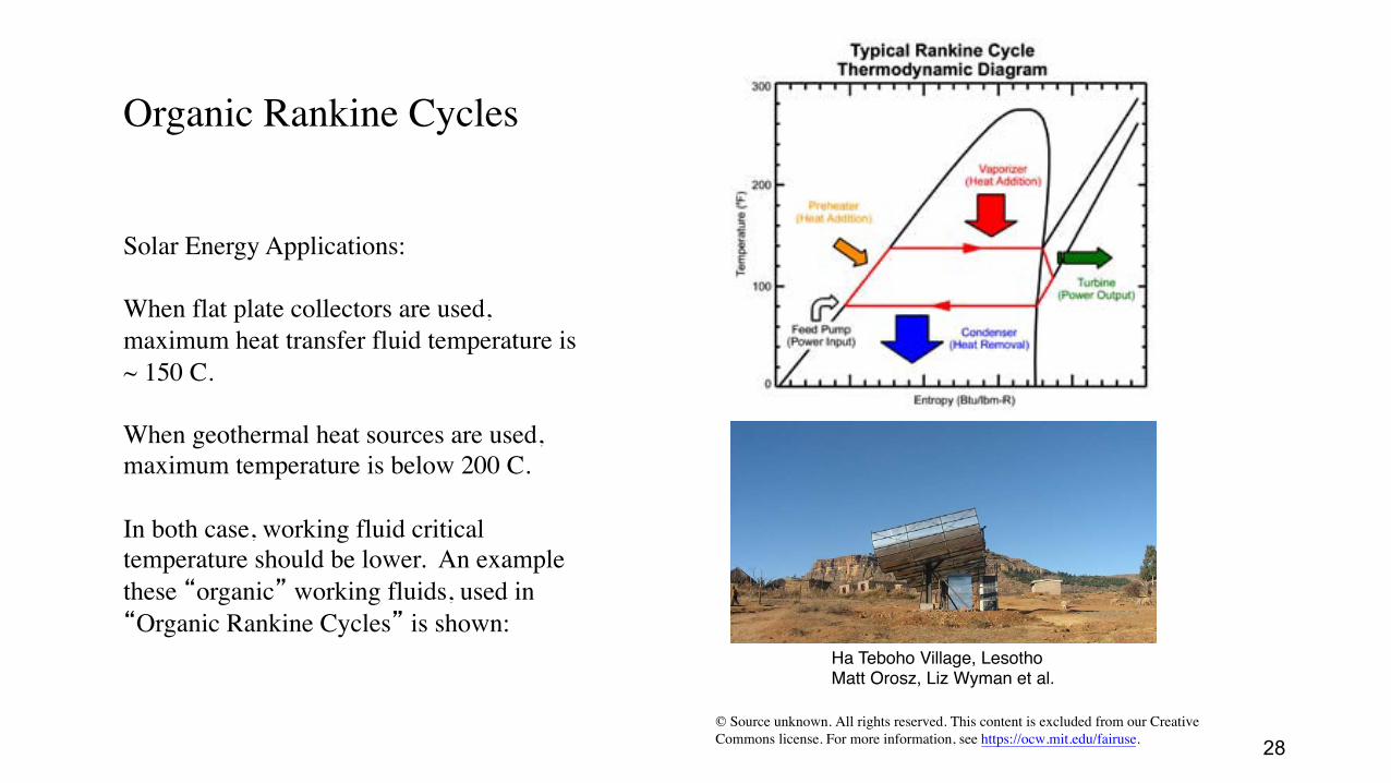
Organic Rankine Cycles
Solar Energy Applications:
When flat plate collectors are used,maximum heat transfer fluid temperature is ~ 150 C.
When geothermal heat sources are used,maximum temperature is below 200 C.
In both case, working fluid criticaltemperature should be lower. An examplethese �organic� working fluids, used in �Organic Rankine Cycles� is shown:
Ha Teboho Village, LesothoMatt Orosz, Liz Wyman et al.
© Source unknown. All rights reserved. This content is excluded from our Creative Commons license. For more information, see https://ocw.mit.edu/fairuse. 28

MIT OpenCourseWare https://ocw.mit.edu/
2.60J Fundamentals of Advanced Energy Conversion Spring 2020
For information about citing these materials or our Terms of Use, visit: https://ocw.mit.edu/terms.


![Thermomechanical Analysis [TMA] [NETZSCH]](https://img.pdfslide.net/doc/110x75/55cf940b550346f57b9f3bd8/thermomechanical-analysis-tma-netzsch.jpg)