Embed Size (px)
Citation preview

1
Thermopatch
Y151 Thermo-Seal Temporary Marking Machine
Operator's Manual
47117-MAN Rev 1214

2
Table of Contents EC - STATEMENT OF CONFORMITY ............................................................................................................. 4
Description .................................................................................................................................................. 5
Safety Tips ............................................................................................................................................... 5
Installation .................................................................................................................................................. 6
What Did You Receive? ........................................................................................................................... 6
Transport Instructions ............................................................................................................................. 7
Installing the Machine ............................................................................................................................. 7
Electrical Requirements .......................................................................................................................... 7
Changing the Input Voltage Setting ........................................................................................................ 8
Pneumatic Requirements ........................................................................................................................ 7
Label Tape Storage Rack Installation ...................................................................................................... 9
Operating the Thermo-Seal ...................................................................................................................... 10
Ink Cartridge Installation ....................................................................................................................... 10
Inserting the Label Marking Tape ......................................................................................................... 11
Machine Operation ............................................................................................................................... 12
LCD panel ............................................................................................................................................... 13
Customizing the Y151 Thermo-Seal .......................................................................................................... 14
Temporary Marking .................................................................................................................................. 17
Sealing Label Tags and Organization ..................................................................................................... 17
Interrupting the Sealing Cycle ............................................................................................................... 19
Troubleshooting ........................................................................................................................................ 20
Maintenance ............................................................................................................................................. 22
Daily Cleaning & Maintenance .............................................................................................................. 22
Weekly Cleaning & Maintenance .......................................................................................................... 22
Semi-annual Cleaning & Maintenance .................................................................................................. 22
Heater Shield ......................................................................................................................................... 23
Tape Guide ............................................................................................................................................ 23
Label Tape Drive “O”-Ring ..................................................................................................................... 24
Drawings and Parts Listing ........................................................................................................................ 25
Electrical Drawings ................................................................................................................................ 26
Pneumatic.............................................................................................................................................. 30
Mechanical ............................................................................................................................................ 33

3
Specifications of the Y151 Thermo-Seal ................................................................................................... 40
Warranty ................................................................................................................................................... 41
Copyright and Trademarks ....................................................................................................................... 42
Thermopatch Customer Service ............................................................................................................... 43
List of Tables Table 1 — EC Compliance ........................................................................................................................... 4 Table 2 — Short Cut Function Keys ........................................................................................................... 14 Table 3 — Settings Menu .......................................................................................................................... 15 Table 4 — Special Mode ........................................................................................................................... 16 Table 5 — Troubleshooting ....................................................................................................................... 20 Table 6 — Specifications: 230 Volts .......................................................................................................... 40 Table 7 — Specifications: 115 Volts .......................................................................................................... 40
List of Figures Figure 1 — Power Entry Module, 115 V ..................................................................................................... 8 Figure 2 — Power Entry Module, 230 V ..................................................................................................... 8 Figure 3 — Label Tape Storage Rack Installation ........................................................................................ 9 Figure 4 — Ink Ribbon Cartridge Installation ............................................................................................ 10 Figure 5 — Label Marking Tape Insertion ................................................................................................. 11 Figure 6 — LCD Display ............................................................................................................................. 13 Figure 7 — Tape Guide.............................................................................................................................. 23 Figure 8 — “O” Ring location .................................................................................................................... 24 Figure 9 — “O” Ring Replacement ............................................................................................................ 24 Figure 10 — Y151 Electrical Schematic ..................................................................................................... 26 Figure 11 — Electrical Chassis Assembly (P/N 47091) .............................................................................. 27 Figure 12 — Heater Unit Assembly ........................................................................................................... 28 Figure 13 — Press Arm Switch Assembly (P/N 47071) ............................................................................. 29 Figure 14 — Pneumatic Diagram .............................................................................................................. 30 Figure 15 — Press Arm Cylinder Assembly ............................................................................................... 31 Figure 16 — Air Filter Pressure Regulator Assembly (P/N 47094) ........................................................... 32 Figure 17 — Dynamic Knife Actuation Spring Assembly .......................................................................... 33 Figure 18 — Dynamic Knife Assembly (Y150 Only) ................................................................................... 34 Figure 19 — Machine Top Cover Assembly and Accessories ................................................................... 35 Figure 20 — Printer Head Assembly ......................................................................................................... 36 Figure 21 — External Tape Guide Assembly ............................................................................................. 37 Figure 22 — Machine Top Cover & LCD Panel Assembly ......................................................................... 38 Figure 23 — SPA 47292 Dynamic Knife Actuation Spring Assembly ........................................................ 39
4
EC - STATEMENT OF CONFORMITY As manufacturer the company
Thermopatch BV Draaibrugweg 14-16 1332 AD ALMERE - NETHERLANDS
confirms that the machine for temporary marking Thermo-Seal Y-151meets the requirements in the EC directives for machine safety and health rules and is in accordance with the EC directives for machinery listed in Table 1.
The Thermo-Seal Y-151 meets the requirements in the EC directives for low voltage and electromagnetic compatibility in accordance with the EC directives listed in Table 1.
The Thermo-Seal Y-151 meets the requirements in the EN listed in Table 1.
Directive Title
73/23/EEC Low Voltage directive
89/336/EEC EMC Directive
89/392/EWG EC Machinery Directive
89/368/EWG EC Machinery Directive
EN 61000-4-2 till 6 EMC Testing & Measurement Techniques “EMC Immunity Test”
EN 61000-4-11 Testing and Measurement Techniques, Voltage Dips, Short Interruptions, and Voltage Variations Immunity Test
EN 55014-1 & -2 EMC “household appliances, electric tools and similar apparatus”
EN 55022 EMS Testing Standard “Information Technology Equipment”
Table 1 — EC Compliance
J. Bausch Director

5
Description The Y151 Thermo-Seal is a machine for the temporary marking of garments and other textile items.
Temporary marking of a garment or textile item is achieved without the use of chemical solvents or other harmful materials. By means of an ink ribbon cartridge, a code (maximum of 12 characters per label) is printed directly onto the thermo-seal label tape, and it is sealed directly onto the garment or textile item.
Most garments or textile items can be marked directly. For garments over very sensitive fabric, there are alternative methods of fixing the temporary label to the garment. The most common option is to print an extra-long label. The extra-long label is inserted through the button hole of the garment, and then the ends are sealed together. Another option is to seal directly onto a “flag tag”. The flag tag is then stapled or pinned onto the garment.
The Thermo-Seal label type is specifically designed to adhere to the garment or other textile item through the cleaning process and then be easily removed without leaving any label residue on the garment. Thermo-Seal label tape is available in ten different colors.
The colors of the Thermo-Seal label tape, and the printed code on the label, offer a variety of ways to sort garments.
The Y151 Thermo-Seal machine operates electrically and pneumatically, through use of compressed air. The code to be printed on the label tape is entered through the machine keyboard. Raising the Press Arm engages the pneumatic system to automatically cut and seal the label tape onto the garment or textile item.
Time, temperature, and other optional settings can be entered through the machine keyboard. The time and temperature, as well as other information, can be viewed from the Keyboard LCD Panel.
The new heater unit design, as well as electronics, ensures the consumer of lower energy consumption and a safer work environment.
Safety Tips The Y151 Thermo-Seal machine has been designed with optimum safety for the machine operator in mind. However, there are some precautions that must be taken when operating and servicing the machine.
Always turn off and unplug the machine when doing maintenance or cleaning the machine.
Ensure that there is sufficient space around the machine. Cables and connections must not get jammed.
Do not come in direct contact with the Heating Unit, as contact will cause burns.
6
Installation
What Did You Receive? The Y151 Thermo-Seal machine has been packed in a cardboard shipment container with laminated foam protection cradles on each end to prevent any damage from shipping. Various components of the Y151 Thermo-Seal machine can be found packaged within. The Y151 Thermo-Seal comes complete with the following components:
• Y151 Thermo-Seal machine with keyboard
• Ink Ribbon Cartridge RC2410-15
• Line Power Cord 115 volt #20080-70 or 230 volt #41969
• Label Tape Cassette Storage Rack #47068
• Label Tape Cassette, quantity of 6 #47083
• A roll of white Thermo-Seal Label Tape #TS4635-01
• Air Filter Pressure Regulator #47094
• Main air line hose #DH-6795
• Rubber Sealing Platen #DH-3187
• Button head socket hex screws, 2 #21061-26-N
• Hex L-Key, 4mm #24085-14 (prior to January 2015)
• Ez-Off Cleaner Thermopatch #DH-6873 or SPADH-6873
If one of these components is missing or damaged, please contact your Thermopatch Sales
Representative. Available Accessories for Machines produced beginning January 2015
• TP P/N 47309 1.5 m (60") of 6mm Tubing • TP P/N 47310 6 mm Male Connector • TP P/N 47311 Metric Hex Key Kit (contains sizes 2.5, 3-6 mm) • DH-3187 Sealing Platens Add 2 additional platens to the kit.
Thermo-Seal Label Marking Tapes — additional colors are available
TS4635-01 White TS4635-08 Green
TS4635-02 Tan TS4635-09 Red
TS4635-03 Blue TS4635-11 Orange
TS4635-05 Gray TS4635-13 Pink
TS4635-06 Lavender TS4635-14 Gold
TS4635-07 Yellow
7
Transport Instructions Upon receipt, your Y151 Thermo-Seal machine is packed in a cardboard shipment container with laminated foam protection cradles for protection of your machine during shipment. Retain original packaging in case the machine should need to be returned for service. Please let the machine cool down before packing the machine in the shipment container.
Installing the Machine Take the Y151 Thermo-Seal out of the shipment container and put the machine on a worktable near a grounded socket. Ensure there is sufficient free space around the machine.
Pneumatic Requirements The Y151 Thermo-Seal Machine also requires a clean dry air supply to operate properly. The line pressure coming into the Y151 Thermo-Seal Air Filter Pressure Regulator should be a minimum of 70 P.S.I. or 5 Bars. This is not the final pressure setting for the Air Filter Pressure Regulator on the Y151 Thermo-Seal machine.
To confirm the machine air pressure is correct, check the gauge located on the front of the filter. The gauge should register 60 P.S.I. (Imperial measurement) or 4 Bars (metric measurement).
1. Connect a clean dry air supply to the Air Filter Pressure Regulator. 2. Connect the Air Filter Pressure Regulator by screwing the component onto the threaded elbow,
positioning the gauge so it can be read. 3. Connect the Air Hose by pushing the receptacle firmly onto Air Inlet Fitting. Make sure the air
line is connected securely and the air gauge is working. 4. To adjust air pressure setting, pull up the knob on top of the Air Filter Pressure Regulator to
unlock the adjustment knob. 5. Slowly turn the knob clockwise to increase air pressure or counterclockwise to decrease air
pressure until the gauge registers 60 P.S.I. or 4 bars. 6. Push down on the knob to lock the current setting in place.
CAUTION! The maximum machine operating pressure is 100 P.S.I. or 7 Bars. The Y151 Thermo-Seal machine comes pre-set at 60 P.S.I. or 4 Bars.
Oil or water in the air supply will damage the valves and cylinders of the machine. Damage from water or oil IS NOT covered under warranty

8
Electrical Requirements Connect the Y151 Thermo-Seal Machine to the electricity grid (230V or 115V alternating current). Use the Line Power Cord provided with the machine. Electrical Specifications: 115 volts (50/60 HZ) Single Phase; 230 volts (50 HZ) Single Phase. All 230v machines use two 250v – 3.15 amp fuses. All 115v machines use two 250v – 6.3 amp fuses.
Figure 1 — Power Entry Module, 115 V
Figure 2 — Power Entry Module, 230 V
Changing the Input Voltage Setting
1. Turn off the machine using the ON/OFF switch the Electrical Chassis Assembly 2. Disconnect the power cord from the machine 3. Note the Line Voltage Indicator on the Power Entry Module located on the Electrical Chassis
Assembly. Refer to Figure 1 for the 115 VAC setup, and Figure 2 for the 230 VAC setup. 4. Carefully pull open the Power Entry Module Fuse Holder using the tab located on the right hand
side of the Power Entry Module. 5. Carefully remove the Fuse Holder from the Power Entry Module 6. Remove the two fuses from the fuse holder and replace with two fuses proper to the desired
voltage. For 115 Volts, use P/N 20015-32, 250 VAC 6.3 AMP; for 230 Volts, use P/N 20015-26, 250 VAC 3.15 AMP
7. Rotate the fuse holder to show the desired voltage in the Power Entry Module window. Refer to Figures 1 & 2
8. Carefully re-install the fuse holder in its slot to show the desired Line Voltage in the Power Entry Module Window.
9. Close the Fuse Holder on the Power Entry Module. 10. Connect the correct power cord for the voltage to the Machine 11. The machine is ready to be operated from your desired VAC. 12. Refer to the operating instructions to operate the machine.

9
Label Tape Storage Rack Installation The Y151 Thermo-Seal machine comes complete with a Label Tape Storage Rack and six Label Tape Cassettes. The rack can hold a maximum capacity of eight Label Tape Cassettes.
Attachment of the Label Tape Storage Rack requires the use of a 4mm L-Hex Key provided. The Label Tape Storage Rack is attached to the Y151 Thermo-Seal machine chassis with the two M6 x 1.0 x 40mm long screws provided. Insert the screws through the clearance holes in the Label Tape Storage Rack engaging the threaded inserts in the machine chassis. Use the 4mm L-Hex Key to tighten the screws.
Slide the Label Cassettes (6) over the square center post of the Label Tape Storage Rack. Correct position of the Label Tape Cassettes is with the hinge portion of the cassette towards the back and the slotted opening towards the front.
Figure 3 — Label Tape Storage Rack Installation

10
Operating the Thermo-Seal
Ink Cartridge Installation The Y151 Thermo-Seal machine comes complete with an Ink Ribbon Cartridge, Thermopatch part #RC2410-15. The Ink Ribbon Cartridge is required to print the desired code onto the temporary label tape.
To Install the Ink Ribbon Cartridge:
1. Open the hinged Machine Top Cover all the way back until it comes to rest.
2. Remove the Ink Ribbon Cartridge from the box and the sealed plastic bag.
3. Clasp the tabs on each side of the Cartridge (A) and guide the Ink Ribbon between the Ink Ribbon Mask and the Printer Head. When properly installed, the Cartridge will snap in place.
4. Turn the Ink Ribbon Advance Knob (B) clockwise to advance the Ink Ribbon and remove any folds that may have occurred during insertion of the Ink Ribbon Cartridge.
Figure 4 — Ink Ribbon Cartridge Installation

11
Inserting the Label Marking Tape
1. Switch the Power Entry Module Switch “ON.” 2. Place the Label Marking Tape into a Label Tape
Cassette and place the Cassette onto the Label Tape Cassette Storage Rack.
3. Pull out approximately 12” or 30cm of tape from the Label Tape Cassette.
4. Insert the Label Marking Tape into the Tape Feed Guide entrance, making sure the adhesive (shiny) side faces the front of the machine.
5. Push the Label Marking Tape into theTape Feed Guide until it can go no further.
6. Depress the F1 (Load Tape) key. The label tape will begin to advance toward the heater. Once the label tape is visible in front of the heater, release the F1 key. Raising the machine’s press arm all the way up will cut the tape and complete the load tape function. This action will also align the label tape and ready the machine for printing.
Should you encounter a splice in the roll (marked by silver tape), remove the section using scissors and re-insert the label marking tape into machine.
Figure 5 — Label Marking Tape Insertion

12
Machine Operation Before printing and sealing with your Y151 Thermo-Seal machine, make sure you have completed all instructions for installation (see Installation Section). In review, the following should be completed:
• Loaded the Label Marking Tape into the Tape Feed Guide. • The green “POWER ON” LED is illuminated on the LCD Panel. • The green “HEAT ON” LED is pulsing or flashing on the LCD Panel. • Verified that no oil or water is in the air supply. • Verified that there are no air leaks • Pressure is set to 60 PSI (4 BAR) • Ink ribbon is firmly snapped into place. • Label tape is properly loaded.

13
LCD panel Before you begin printing and sealing, you should understand the features, messages and icons present on the LCD panel of the Y151 Thermo-Seal machine.
Figure 6 — LCD Display
The picture of the LCD above illustrates the Y151 in “Ready” mode.
A. Illuminated green LED indicates the power is “ON.” B. Illuminated green LED indicates the heat is “ON” and rising to operating temperature. Flashing
LED indicates the machine has reached operating temperature. C. Illuminated red LED indicates label is ready to be sealed. D. Illuminated red LED indicates the machine is sealing. E. Machine Operating Temperature icon: Temperature in either Celsius or Fahrenheit. The picture
above shows the machine is operating at the factory setting 176° C or 349° F. F. Sealing Time: The normal sealing time is 2.7 seconds. An optional 4.8 seconds sealing time is
available for thick, damp, or dirty objects. G. Operation mode: Label Quantity, Single Label or Continuous. H. Total Production Counter- Number of labels sealed since the machine was installed. The
continuous counter cannot be reset. I. Bundle Quantity: Number of labels to be sealed per bundle. Counter will count downward from
the number placed into the Bundle Quantity queue by the machine operator. J. Text Entry Line: up to 12 alphanumeric characters can be entered to be printed on labels. K. Daily Production Counter: Number of labels sealed in the time in which the machine has been
operating. Resets after machine is switched off. L. Label Length: NL stands for Normal Length. Extra Length “EL” is available to the machine
operator as well.

14
Customizing the Y151 Thermo-Seal The Y151 Thermo-Seal machine software has a number of factory default settings, such as: Sealing Temperature, the Display Language, the Label Marking Tape Length, and the Password to the Special Settings Mode.
The Y151 Thermo-Seal software can be customized to your personal requirements. These changes to the factory settings in the machine software can be accessed through the Special Settings Mode in the Keyboard Options F8 menu.
The Y151 Thermo-Seal factory settings are sufficient for normal daily processing of garments and textile items. However, shortcut Thermo-Seal Function Keys are provided to allow for changes to the standard software settings while processing. The Thermo-Seal Function Keys allow for the exceptions that are encountered without having to continually change factory software settings.
Table 2 — Shortcut Function Keys
Key Display Description
F1 Cut Tape Cut Label Tape
F2 Load Tape Load Label Tape
F3 2.7 / 4.8 Toggle between Normal and Heavy seal time
F4 NL / EL Toggle between Normal Length and Extended Length
F5 Display Totals Toggle Display Totals On/Off
F6 Double Strike Print Label text darker
F7 Reset Day Counter Sure Y/N
Reset the Daily Counter
F8 1 = Settings 2=Special Mode
3=End
Activate Settings menu Activate Special menu
Exit and return to display
F9 Repeat Last Label Repeat Previous Label text
F10 Insert On/Off
Display last character in text line
Numlock Current operating temperature Toggles between operating temperature & main display
Backspace No Display shown Ends bundle or series, display is ready for new entry

15
Table 3 — Settings Menu
Menu Display Description Adjustment Default
1 = Temperature Temperature Change Temperature Up/Down Arrow Key 1° or 1° C 176°C/349°F
2 = Seal Time 1 = Normal Time 2 = Ext. Time
Change Normal Seal Time Extended Seal Time (heavy)
Up/Down Arrow Key 0.1 second Left/Right Arrow Key 1.0 second
2.7 Sec
4.8 Sec
3 = Sec. S. Time Second Seal Time (Long Label Tag)
Up/Down Arrow On/Off Left/Right Arrow Key On/Off
On
3 = Label Length 1 = Normal Label 2 = Ext. Label
Normal Extended Label
Up/Down Arrow Key 1 unit Left/Right Arrow Key 10 units
10 100
4 = Characters Characters Number
Change number of characters in use
Up/Down Arrow Key 1 character Left/Right Arrow Key 10 character
6
5 = Automatic Numbering
Auto Numbering Off
Turns Auto Numbering On or Off
Up/Down or Right/Left Arrow Key turns Auto Numbering On or Off
Off
6 = Language Language 1 = Deutsch 2 = English 3 = Espagnol 4 = Francais 5 = Nederlands
Choice of Operation Language
Up/Down Arrow Key cycles through the Language menu. To select, press the Enter Key
English
7 = Celsius/Farenheit Celsius/Fahr Change Temperature Scale Up/Down Arrow Key selects desired Temperature Scale
Celsius
8 = Serial Port Serial Comm Off
Serial Port Function Setting
Up/Down Arrow Key selects desired setting: On or Off
Off
9 = Operation Mode 1 = Label Quant 2 = Single Label 3 = Continue
Operation Mode
Select menu number
1
Sub Menu Sub Menu
1 = Invoice Before 2 = Invoice After 3 = No Invoice
Use of Invoice
Select menu number
3

16
Table 4 — Special Mode
Menu Display Description Adjustment Default
Type Password
Password required to make changes to defaults
Type in password and press Enter Key Password Y150TP
1 Factory Reset Sure Y/N
Change factory settings Press Y for Yes or N for No N
2 Password On
Turns Password function On or Off
Up/Down Arrow Key On/Off ON
3 Edit Passw Type Sure Y/N
Edit Password and set new password
Enter Y for Yes or N for No Type in current password
and press Enter Key
Default Password Y150TP
Sub Displays
Change Password Password again
Succeeded
Requests new password Verification of new password
New password is set
Enter new password Re-enter new password
4 Temperature Offset
Change temperature offset setting
Up/Down Arrow adjust 1°C or 1° F Left/Right Arrow adjust 10°C or 10° F
0
5 Left Margin 10
Adjust left margin label distance
Up/Down Arrow adjust 1 unit Left/Right Arrow adjust 10 units
10
6 Print Quality 2
Adjustments to the label print quality
Up/Down Arrow adjust 1 unit 2

17
Temporary Marking Temporary, removable marking is used by laundries, hospitals, hotels, textile suppliers, textile care companies, and various other industries. The Y151 Thermo-Seal Machine is designed to be used for temporary marking of garments and textile items.
Almost all garments or textile items can be marked directly or indirectly. Because of the variety of fabrics, it is very important to follow some instructions on textile care.
The default operating temperature of the Y151 Thermo-Seal machine is 176°C or 349°F. Materials that are sensitive to heat cannot be marked directly.
The mark on garment labels “Only wash/iron at low temperature” can also indicate that the colors are sensitive to high temperatures or that the heating of the finish on the fabric can cause the color to change.
If you are not sure about the sensitivity of the fabric, please mark the garment or textile item indirectly. If there is no possibility for indirect marking, the garment or textile item must be washed in a washing net that has been marked. Be very careful when you want to mark articles that must be cleaned chemically. The message “Only Dry Cleaning” normally means that the garment or textile item is sensitive to heat, pressure, and detergents.
Sealing Label Tags and Organization There are ten different colors of Label Marking Tape for organizing and sorting purposes. The colored tapes can be used for both the entire operations for a customer and for the different lots.
Bundle Lot System One of the more popular systems is the Bundle Lot System. Garments from multiple customers or sources can be mixed while washing but easily sorted.
Typical labels for a Bundle Lot System are as follows: 1. A01-05 2. 3A01-05
A= Week number 01= Lot number in that week 05= Customer bundle number
3= Number of pieces in the order A= Week number 01= Lot number in that week 05= Customer bundle number
The tape color is changed at the end of each lot. The lot number is advanced by 1 and the bundle number is reset to 1. The colors are always used in the same sequence.
18
Day Lot System On the Day Lot System, one color is designated for all articles received on a specific day of the week. All laundry is processed for a 1 or 2 day turnaround and the entire lot is sorted together. Items that get misplaced or out of lot are easily identified by their color.
1. M 12345 or 1-12345 2. 01M2345 3. 03M2345
M or 1= Monday or Day 1 12345= Invoice number
01= Week number M= The day 2345= Invoice number
03= Number of pieces in order M= The day 2345= Invoice number
Route Location System This system uses the color of the tag to designate the route or the store location. In many cases, items are processed, folded, and sent to the store location for sorting by counter personnel. The number of locations is limited to the number of colors available.
1. 24-1234 2. 3-24-1234
24= Location Number 1234= Invoice or bundle number
3= Number of pieces in the order The rest is the same as Item 1.
Invoice Number System The number on the tag is the invoice number. It is often accompanied by the number of pieces, the day of delivery, the location or lot number. Tag color is usually changed after a set number of bundles or at the end of each day.
1. 3-24-12345 2. 3M1234
3= Number of pieces 24= Location 12345= Invoice number
3= Number of pieces M= Day of delivery 1234= Invoice number
Hotel Room Number System This system uses the room number and the date the item is received on the tag. The color changes each day so that items that are short are easily indentified. Occasionally the number of pieces in the order is listed as the first number.
1. 20-1234 2. 03-1235
20= Date received 1234= Room number
03= Number of pieces in order 1235= Room number
Nursing Home/Elderly Home Today, most Nursing Homes use a permanent label to identify the resident’s garments. When a temporary label is used, the tag usually is used to denote location. The numbering usually denotes the room or apartment location.
1. B 435 2. 1435 B= Building designation 435= Room number
1435= Room or apartment number

19
Normal Label Tag Marking Label Tags are sealed directly onto the garment or textile item. Placement of the Label Tag should be done in the correct position for the garment or textile item.
Thick, Dirty or Damp Garments and Textile Items Label Tags are sealed upon thick, dirty, or damp garments and textile items in the same manner as described in the previous section, Normal Label Tag Marking. However, thick, dirty, or damp garments and textile items require more time to securely adhere the Label Tag to the garment or textile item. Therefore, a Sealing Time of 4.8 seconds “Heavy” is used to correctly seal the Label Tag to the garment or textile item. The machine operator can change from Normal seal time to Heavy seal time by using the F3 Thermo-Seal function key.
Sensitive Garments or Textile Items Label Tags that cannot be sealed directly on sensitive garments or textile items can be sealed indirectly using the “Extra Length” option. The Extra Length option can be activated by using the F4 function function key. When the Extra Length option is activated, the display will show “EL”. The Extra Length tag will have the desired code printed onto the label tag.
The Extra Length label tag can be made longer by pressing the F4 function key when the printed label is positioned in front of the heater element and ready to be sealed.
Raise the press arm to cut the tag. Pass the long label tag through the top buttonhole of the garment or opening in the textile item. Fold the ends of label tape together and position the ends in front of the sealing platen, with the printed code facing the heater.
Raise the press arm to seal the ends of the tape together.
Attention! Thermopatch cannot take any responsibility for any damages to garments or textile items that occur by the use of this machine.
The Use of Flags on Sensitive Garments There is an alternative indirect Label Tag marking method. The alternative method uses “flags.” The Label Tag with desired code is printed, cut, and sealed onto the flag. The flag is then fastened to a button on the garment, in a manner in which the flag cannot come loose.
Attention! To ensure proper sealing of the Label Tag ends, be sure that both ends of the Label Tag are parallel to each other. To complete the seal, hold the Label Tag at the garment or textile item.
CAUTION! Be sure to keep your fingers clear of the Sealing Platen.
Interrupting the Sealing Cycle At any point in the process of printing, cutting, or sealing, the machine operator can interrupt the Sealing Cycle. Depressing the Esc key will exit the process cycle allowing the machine operator to initiate any necessary changes or activation of sub-routes.

20
Troubleshooting Before referring to the following information, check for proper setup and operation as outlined in preceding sections of this manual. Some repair procedures require a person with mechanical and electrical skills.
Table 5 — Troubleshooting
Failure Possible Causes Solution
Machine does not function Not connected to outlet No line power to outlet
Fuses blown in Power Entry Module
Check outlet
Check fuses in Power Entry Module
Sealing pressure fluctuates Leak in Air Supply Hose
Dust or water in air lines, regulator, or Solenoid Valve
Repair or replace
Disassemble and clean
Machine does not seal Insufficient air pressure
Press Arm Limit Switch defective
Solenoid Valve not engaged
Check and adjust air pressure regulator
Check wiring or replace switch
Check wiring and air lines at fittings; replace solenoid.
No Heat No power to machine
Heater Element defective, or Temperature Sensors defective, or Solid State Relay defective or Main Controller Board defective
Check outlet and fuses
Replace
Error Detected: Heater Defective
Defective Heater Element Replace
Error Detected: PT 1600 Defective
Defective Temperature Sensors Replace
Temperature too high or too low Temperature settings have been changed
Temperature sensors are defective
Reset temperature settings
Replace Sensors
Poor sealing quality Temperature setting is incorrect
Air pressure setting is incorrect
Sealing time is incorrect
Heater shield is loose or dirty
Sealing Platen is worn or dirty
See Table 3 — Settings Menu
See Pneumatic Requirements pg 7
See Table 3 — Settings Menu
Correct or clean
Replace or clean

21
Poor printing quality Ink Ribbon Cartridge dry
Ink Ribbon in cartridge not moving
Print head defective
Text spacing incorrect
Replace
Replace
Replace
See Table 3 — Settings Menu
Printed text has horizontal type blanks
Printer Head is defective
Controller Board is defective
Replace
Replace
Dynamic Knife does not cut Label Marking
Dynamic Knife is dull
Dynamic Knife Cylinder is not actuating
Replace
Check air line tube connections or replace Knife Cylinder
Label Marking Tape is jamming in the Tape Guide
Tape Guide is dirty
Splice in Label Marking Tape or fold in tape
Clean Int. & Ext. Tape Guide, see Tape Guide, pg 23
Remove tape and cut off spliced tape section
Unreadable or no LCD Panel Display Loose connection at LCD Panel or Controller Board
Defective Ribbon Cable
Defective LCD Panel
Reset Ribbon at LCD Panel or Controller Board
Replace
Replace
Incorrect Character Spacing on Label Tape
Obstruction in Tape Guide
Worn Spindle Drive Ring
Defective Stepper Motor
Clean Tape Guide
Replace, see Label Tape Drive “O”-Ring, pg 24
Replace
Marks on garment or textile item Ink buildup on Rubber Platen
Ink buildup on Heater Shield
Clean or replace
Textile is discolored during sealing Textile is temperature sensitive or textile care symbols disregarded
Time setting too long
Temperature too high
Mark with Extra Long Label Tag or with Label Flag
Decrease time
Correct temperature
Labels become loose on left side High mechanical load during washing or cleaning
Temperature too low
Sealing pressure too low
Sealing time too short
Replace Rubber Sealing Platen
Correct temperature
Correct pressure
Correct time

22
Maintenance Before beginning any maintenance on your Y151 Thermo-Seal machine, finish any process cycles that may be started. After the process cycles have been completed, maintenance upon the machine may commence.
Attention! Before beginning maintenance, unplug the Main Air Supply Line Hose to the Air Filter Pressure Regulator and unplug the Line Power Cord from the electrical supply.
Maintaining a clean machine will extend the service life of the Y151 Thermo-Seal machine. The following is the recommended cleaning schedule for various parts of the Y151 Thermo-Seal machine.
Daily Cleaning & Maintenance To optimize performance of your Y151 Thermo-Seal machine, the following parts or areas should be cleaned on a Daily basis:
• Heater Shield: should be cleaned following the schedule outlined in Heater Shield, pg 23. • Rubber Sealing Platen • Tape Guide: clean following directions in Tape Guide, pg 23
Weekly Cleaning & Maintenance To optimize performance of your Y151 Thermo-Seal machine, the following parts or areas should be cleaned on a Weekly basis:
• Machine Top Cover/LCD Panel: remove dust and lint. • Interior Machine Platform: remove dust and lint.
Semi-annual Cleaning & Maintenance To optimize performance of your Y151 Thermo-Seal machine, the following parts or areas should be cleaned on a semi-annual basis:
• Machine Electronics Compartment: underside of Interior Machine Platform. Requires removal of Right and Left Machine Covers.
• Heater Shield: inspect, clean, or replace. • Rubber Sealing Platen: inspect, clean, or replace. • External Tape Guide Teflon Shield: inspect, clean, or replace.

23
Heater Shield Clean the Heater Shield several times a day. To clean the Heater Shield, use the provided cleaning paste, “Ez-Off” (Thermopatch #DH-6873 or SPADH-6873).
Ez-Off cleaning paste is available for purchase through our Customer Service network.
To clean the Heater Shield, put some paste on a dry cloth and clean the Heater Shield while it is still warm, but not hot enough to cause burns to your skin. When cleaning the Heater Shield, never use chemicals, solvents or abrasives that can scratch the Heater Shield.
A Heater Shield that is no longer smooth should be replaced. A Heater Shield that develops a buildup of ink or of which the smooth surface has been damaged will affect the print quality of the Label Tag.
Built-up layers of ink or dirt on the Heater Shield can cause an insulating effect. The insulating effect can cause a reduction in surface temperature at the Heater Shield. Lower surface temperature is the main cause of Label Tag losses during the laundering process.
Tape Guide
The Tape Guide in the Y151 Thermo-Seal machine is accessible from the front of the machine under the hinged Machine Top Cover.
Open the machine and run a clean, dry cloth along both surfaces.
Figure 7 — Tape Guide

24
Label Tape Drive “O”-Ring The Label Tape Drive “O”-Ring transports the Label Marking Tape through the Tape Guide. The Label Tape Drive “O”-Ring is a part that will wear over a period of time. The life cycle of this part is relative to the amount of machine usage.
The following narrative with sequence of pictures will take you through the process of removal and installation of a new Label Tape Drive “O”-Ring.
Prior to opening the Machine Top Cover to expose the Tape Guide and Label Tape Drive “O”-Ring, switch the power to the machine to the “Off” position and unplug the machine from its electrical source. The picture to the left illustrates the Machine Top Cover of the Y151 Thermo-Seal open with the External Tape Guide removed.
Figure 8 — “O” Ring location
Loosen (but do not remove) the two socket hex cap screws retaining the Internal Tape Guide. Tilt the Internal Tape Guide forward (toward you). Remove the Label Tape Drive “O”-Ring by sliding the “O”-Ring up off of the Label Tape Drive Spindle. Install the new “O”-Ring by sliding the “O”-Ring down over the Label Tape Drive Spindle until it is seated in the “O”-Ring groove on the Drive Spindle.
After the new “O”-Ring has been installed, slide 0.015” [0.4mm] shim stock at each end, between the Upper Chassis Platform and the Internal Tape Guide. Tighten the socket hex cap screws, and reinstall the External Tape Guide.
Figure 9 — “O” Ring Replacement

25
Drawings and Parts Listing On the following pages, the reader will find technical drawings and corresponding parts listings of the Y151 Thermo-Seal machine. The technical drawing illustrating a particular sub-assembly or area of the machine will precede the parts listings.
The reader will find that the technical drawings and corresponding parts listings are arranged by category. Those categories in order are:
1. Electrical 2. Pneumatic 3. Mechanical

26
Electrical Drawings
Figure 10 — Y151 Electrical Schematic
27
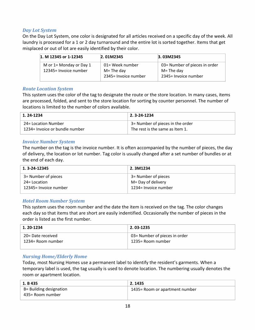
Figure 11 — Electrical Chassis Assembly (P/N 47091)

28
ITEM # DESCRIPTION QTY Part Number
1 Heater Unit Assembly 1 47111 2 Heater Element Assembly 1 47123 3 RTD Temperature Sensor Assembly 1 47136
Figure 12 — Heater Unit Assembly
29
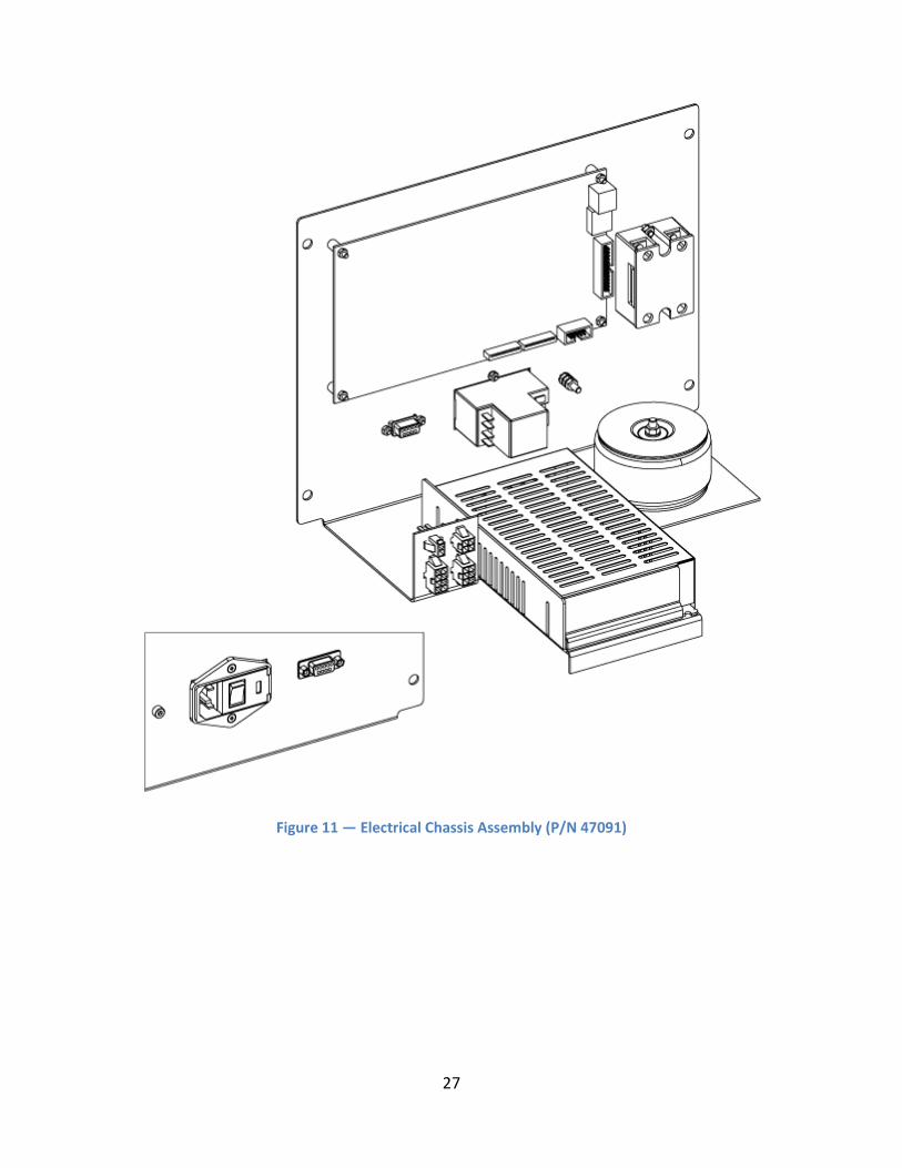
Figure 13 — Press Arm Switch Assembly (P/N 47071)

30
Pneumatic
Figure 14 — Pneumatic Diagram
31
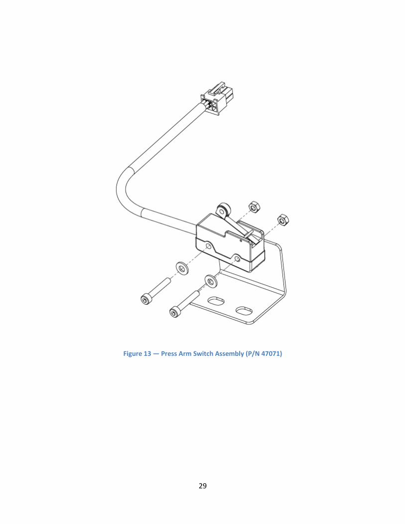
ITEM # DESCRIPTION QTY Part Number
4 Socket Hex Set Screw, M10 X 1.5 X 30mm 1 21049-13-H 5 Press Arm Cylinder 1 22010-74 6 Exhaust Breather 1 22046-24 7 Socket Hex Cap Screw, M6 X 1.0 X 90mm 1 21043-25-E 8 Pneumatic Solenoid Valve 1 22046-23 9 Solenoid Valve Wire Harness 1 47084 10 Socket Hex Cap Screw, M3 X 0.5 X 30mm 1 22046-23 11 Solenoid Valve 1 21043-14-B 12 Press Arm Cylinder Rod End 1 47023
Figure 15 — Press Arm Cylinder Assembly

32
ITEM # DESCRIPTION QTY Part Number
13 Air Pressure Gauge 1 22045-101 14 Quick Connect Hole Adapter 1 DH-6797 15 Air Filter Pressure Regulator 1 22045-91
Figure 16 — Air Filter Pressure Regulator Assembly (P/N 47094)

33
Mechanical
ITEM # DESCRIPTION QTY Part Number
16 Static Knife Blade 1 47109 17 Cutter Actuator 1 47228 18 Nylon Locknut 1 21051-31-G 19 M5 Flat Washer 1 21047-06 20 M5 Hex Nut 1 21045-07-A 21 Set Screw 1 92311A431 22 Knife Actuation Spring Assy 1 47292 23 Dynamic Knife Actuation Cylinder 1 47204 24 Dynamic Knife Blade 1 47227
Figure 17 — Dynamic Knife Actuation Spring Assembly

34
ITEM # DESCRIPTION QTY Part Number
25 Static Knife Blade 1 47109 26 Nylon Washer, D 1/4” Inside 1 21028-63 27 Socket Hex Shoulder Screw, ¼” X 3/8” Long (#10-31unc) 1 21006-01-G 28 Dynamic Knife Push Rod 1 47203 29 Hex Jam Nut, M5 X 0.8 1 21045-07-A 30 Dynamic Knife Actuation Cylinder 1 47204 31 Dynamic Knife Blade 1 47227
Figure 18 — Dynamic Knife Assembly (Y150 Only)
35
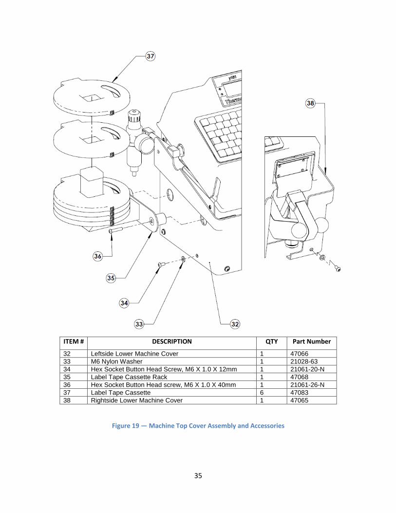
ITEM # DESCRIPTION QTY Part Number
32 Leftside Lower Machine Cover 1 47066 33 M6 Nylon Washer 1 21028-63 34 Hex Socket Button Head Screw, M6 X 1.0 X 12mm 1 21061-20-N 35 Label Tape Cassette Rack 1 47068 36 Hex Socket Button Head screw, M6 X 1.0 X 40mm 1 21061-26-N 37 Label Tape Cassette 6 47083 38 Rightside Lower Machine Cover 1 47065
Figure 19 — Machine Top Cover Assembly and Accessories

36
ITEM # DESCRIPTION QTY Part Number
39 Printer Head Mask 1 20205-143 40 Printer Head 1 20205-142 41 Socket Hex Cap Screw, M3 X 0.5 X 12mm 1 21043-07-B 42 M3 Spring Lockwasher 1 21046-03-A
Figure 20 — Printer Head Assembly
37
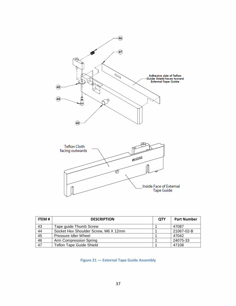
ITEM # DESCRIPTION QTY Part Number
43 Tape guide Thumb Screw 1 47087 44 Socket Hex Shoulder Screw, M6 X 12mm 1 21067-02-B 45 Pressure Idler Wheel 1 47042 46 Arm Compression Spring 1 24075-33 47 Teflon Tape Guide Shield 1 47108
Figure 21 — External Tape Guide Assembly

38
ITEM # DESCRIPTION QTY Part Number
48 Velcro Hook, w/PSA Backing 4 23025-04 49 Compact Slim Line Keyboard 1 20200-48 50 LCD Panel Enclosure Label 1 47098 51 Flat Head Hex Socket Screw, M3 X 0.5 X 8mm 4 21053-01-A 52 Machine Top Cover 1 47054
Figure 22 — Machine Top Cover & LCD Panel Assembly

39
Figure 23 — SPA 47292 Dynamic Knife Actuation Spring Assembly
(for machines manufactured beginning January 2015)
ITEM # DESCRIPTION QTY Part Number
53 Actuator Bracket 1 SPA47193 54 Static Knife Blade 1 47109 55 Dynamic Knife Blade 1 47227 56 Button Head Socket Cap Screws, M3 0.5 x 10z 2 21043-06-BHKZ 57 M5 HEX Lock Nut, M5 x 0.8 z 1 FABLOCKNUT 58 M5 HEX Nut, M5 x 0.8 z 2 FABNUT 59 Socket Head Set Screw, M5 x 20 mm 1 FABSHSETSCREW 60 Clear Plastic Tube, 6 mm x 50 mm 1 SPATUBING6MM 61 Tie Wraps 2 SPAMA-SU2-E2 62 Spring, 8 mm x 40 mm 1 SPA47291 SPA47292 Dynamic Knife Installation Instructions SPA47292INST
Please refer to Figure 17 — Dynamic Knife Actuation Spring Assembly for full view of Static & Dynamic Knife Blades

40
Specifications of the Y151 Thermo-Seal Table 6 — Specifications: 230 Volts
Power consumption 575 w
Power supply 230 v
Temperature 176 °C
Machine height 389 mm
Machine width 556.5 mm
Machine depth (connections included) 432.5 mm
Net weight 18.5 kg
Platen Pad dimensions 14.3 x 34.7 mm
Heater Unit dimensions 35 x 80 mm
Fuses 3.15 amps [5 X 20 mm]
Table 7 — Specifications: 115 Volts
Power consumption 575 w
Power supply 115 v
Temperature 349 °F
Machine height 15.3 ”
Machine width 21.9 ”
Machine depth (connections included) 17.1 ”
Net weight 40.7 lb
Platen Pad dimensions 0.56” x 1.37 ”
Heater Unit dimensions 1.38” x 3.15 ”
Fuses 6.3 amps[0.2” x 0.79”]

41
Warranty
Thermopatch Corporation, Syracuse, New York (“Seller”) warrants this product to be free from defects in material and workmanship under normal use and service. Any part which proves to be defective in material or workmanship within one year of the date of original purchase for use, will be repaired or replaced, at Seller’s option, free of service or labor charges, with a new or functionally operative part. Seller’s liability under the Warranty shall be limited to repairing or replacing at its own factory or through an authorized service distributor or dealer, material which is determined by Seller to have been defective in manufacture and upon which a claim has been made by the original purchaser or user to Seller (or an authorized distributor or dealer) within the warranty period. Claims under this Warranty will be honored only upon written approval by an authorized officer of Seller. Approved return of parts or products will be on a prepaid transportation charges basis only. Claims under this Warranty will be honored only upon Seller’s determination that the claim is covered by this Warranty, and Seller shall incur no obligation under this Warranty prior to such determination. This Warranty does not apply: (1) To any machinery or equipment which has been altered or repaired, except by Seller or its authorized representatives, or (2) to any machinery or equipment which has been subject to misuse, negligence, or accident, including, without limitation, use and operation of such machinery or equipment while parts are loose, broken, out of order, or damaged by the elements. Parts replaced under this Warranty are warranted only through the remainder of the original Warranty. Any and all claims for warranty service must include such information as Seller designates, and shall include specifically the serial number of each unit (if appropriate).
The foregoing shall constitute the sole and exclusive remedy of any using purchaser and the sole and exclusive liability of Seller in connection with this product. THIS WARRANTY IS IN LIEU OF ALL OTHER WARRANTIES, EXPRESS, IMPLIED OR STATUTORY, INCLUDING BUT NOT LIMITED TO, ANY WARRANTY OF MERCHANTABILITY OR FITNESS AND ALL OTHER OBLIGATIONS OR LIABILITIES OF SELLER, INCLUDING ANY TORT LIABILITY, FOR NEGLIGENT DESIGN OR MANUFACTURE OF THIS PRODUCT, OR OTHERWISE. It is expressly agreed that Buyer shall not be entitled to recover any incidental or consequential damages, as those terms are defined in the Uniform Commercial Code, and that Buyer shall have no right of rejection or of revocation of acceptance of any part or all of the goods covered hereby.

42
Copyright and Trademarks © 2011-2014, Thermopatch, Syracuse, New York. No part of this publication may be reproduced by any means without the prior written permission of Thermopatch, Syracuse, New York. Thermopatch, Deco-Print, and the Thermopatch logo are ® trademarks of Thermopatch, Syracuse, New York.

43
Thermopatch Customer Service Thermopatch Corporation’s U.S. and International network of Sales Representatives, as well as its internal Customer Service Department, offer their assistance in the development of effective heat-seal mending, marking, and identification programs.
Thermopatch markets a complete line of heat-seal and marking machines, as well as a complete line of materials and supplies.
• Label Print Machines – Manual, automatic, and computer controlled. • Marking Machines – High speed permanent imprinting of decorative or informative marks on
most woven fabrics. • Heat-Seal Machines – Manual, semi-automatic, and completely automatic, with high inter-
platen pressure to assure excellent adhesion of label tapes and mending materials. • Label Tapes – Specially woven 100% cotton and blends with adhesives to match specific
processing requirements. • The Deco-Print line of products has been specifically designed to offer alternative solutions to
sewn-in labeling and other methods of decorative trimming. An assortment of heat-sealable applications is available including hot paper transfers, screen printed transfers, direct printing, application equipment and supplies, and digital printed transfers.
When ordering machine parts, please include the model and serial numbers of your equipment.
U.S.A.: Thermopatch Corporation P.O. Box 8007 Syracuse, New York 13217-8007
Australia: Thermopatch (Australia) Pty. Ltd. 477 Warrigal Road, Unit No. 9 Moorabbin, Victoria 3189
Telephone: 315-446-8110 Telephone: 011-61-3-9532-5722
Fax: 315-445-8046 Fax: 011-61-3-9532-5652
Toll Free: 800-252-6555 (in the USA only)
Canada: Thermopatch (Canada) Incorporated 25 Groff Place, Unit No. 5 Kitchener, Ontario N2E 2L6
Netherlands: Thermopatch BV P.O. Box 50052 1305 AB Almere Netherlands
Telephone: 519-748-5027 Telephone: 011-31-36-549-1111
Fax: 519-748-1543 Fax: 011-31-36-532-0398
Toll Free: 800-265-6416 (in Canada only)

44
France: Thermopatch France 7 Rue Chappe-Z.I. Des Garennes B.P. 1011 Les Mureaux Cedex 78131 France
Germany: Thermopatch Deutschland Grunteweg 33 26127 Oldenburg Deutschland
Telephone: 011-33-1-3022-0808 Telephone: +49 441-380210 Fax: 011-33-1-3022-1866 Fax: +49 441-3802121
Internet Address: http://www.thermopatch.com E-mail Address: [email protected] If your country is not listed above, please contact Thermopatch Corporation or Thermopatch Netherlands.