Embed Size (px)
Citation preview
Thermostatic Bimetal Designer's Guide
2
ContentsINTRODUCTIONHistory of Solutions...........................................................................................................................4How Thermostatic Bimetal Works..........................................................................................................5How it is Made ..................................................................................................................................6Sizes Available ..................................................................................................................................7Standard Dimensional Tolerances........................................................................................................8-9Alloys and Standard Bimetal Materials.................................................................................................10Standard Test Methods.......................................................................................................................11
BASIC THEORY AND FUNDAMENTAL CALCULATIONSRadius of Curvature......................................................................................................................12-13Flexivity and Thermal Deflection....................................................................................................14-15The Effect of Flexivity Temperature Dependence on Material Selection......................................................15Modulus of Elasticity in Bending.....................................................................................................16-17Thermal Force..................................................................................................................................17Stress as Related to Temperature.....................................................................................................17-18Electrical Resistivity and Resistive Heating.......................................................................................19-21Electrical Resistivity vs Temperature....................................................................................................22Stabilizing Heat Treatment.................................................................................................................23
PHYSICAL AND MECHANICAL PROPERTIESPhysical and Mechanical Properties Table (English).............................................................................24-26Physical and Mechanical Properties Table (Metric).............................................................................27-29
DESIGN CONSIDERATIONSThe Key to Success.......................................................................................................................30-31
THE EMS ADVANTAGEHistory ..........................................................................................................................................32Facilities.........................................................................................................................................32Product Variety................................................................................................................................32Capabilities.....................................................................................................................................32Quality...........................................................................................................................................32Technical Support.............................................................................................................................32
APPENDIX: USEFUL EQUATIONS FOR DESIGNERSDesign Configurations.......................................................................................................................34Keys to Symbols Used in Formulas and General Laws Governing Thermostatic Bimetals.................................34-35Cantilever Strips...............................................................................................................................35U Shaped Elements...........................................................................................................................36Creep Type Discs...............................................................................................................................38Simple Beams..................................................................................................................................40Spiral and Helix Coils........................................................................................................................41Reverse Elements........................................................................................................................43-45Useful Equations for Designers (Metric Units)........................................................................................46Instantaneous Flexivity Values Table.....................................................................................................47Instantaneous Specific Deflection Values Table......................................................................................48
REFERENCES.....................................................................................................................................49
3
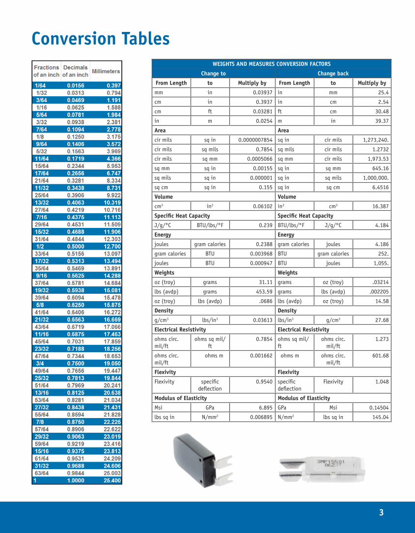
Conversion TablesWEIGHTS AND MEASURES CONVERSION FACTORS
Change to Change back
From Length to Multiply by From Length to Multiply by
mm in 0.03937 in mm 25.4
cm in 0.3937 in cm 2.54
cm ft 0.03281 ft cm 30.48
in m 0.0254 m in 39.37
Area Area
cir mils sq in 0.0000007854 sq in cir mils 1,273,240.
cir mils sq mils 0.7854 sq mils cir mils 1.2732
cir mils sq mm 0.0005066 sq mm cir mils 1,973.53
sq mm sq in 0.00155 sq in sq mm 645.16
sq mils sq in 0.000001 sq in sq mils 1,000,000.
sq cm sq in 0.155 sq in sq cm 6.4516
Volume Volume
cm3 in3 0.06102 in3 cm3 16.387
Specific Heat Capacity Specific Heat Capacity
J/g/°C BTU/lbs/°F 0.239 BTU/lbs/°F J/g/°C 4.184
Energy Energy
joules gram calories 0.2388 gram calories joules 4.186
gram calories BTU 0.003968 BTU gram calories 252.
joules BTU 0.000947 BTU joules 1,055.
Weights Weights
oz (troy) grams 31.11 grams oz (troy) .03214
lbs (avdp) grams 453.59 grams lbs (avdp) .002205
oz (troy) lbs (avdp) .0686 lbs (avdp) oz (troy) 14.58
Density Density
g/cm3 lbs/in3 0.03613 lbs/in3 g/cm3 27.68
Electrical Resistivity Electrical Resistivity
ohms circ. mil/ft
ohms sq mil/ft
0.7854 ohms sq mil/ft
ohms circ. mil/ft
1.273
ohms circ. mil/ft
ohms m 0.001662 ohms m ohms circ. mil/ft
601.68
Flexivity Flexivity
Flexivity specific deflection
0.9540 specific deflection
Flexivity 1.048
Modulus of Elasticity Modulus of Elasticity
Msi GPa 6.895 GPa Msi 0.14504
lbs sq in N/mm2 0.006895 N/mm2 lbs sq in 145.04
4
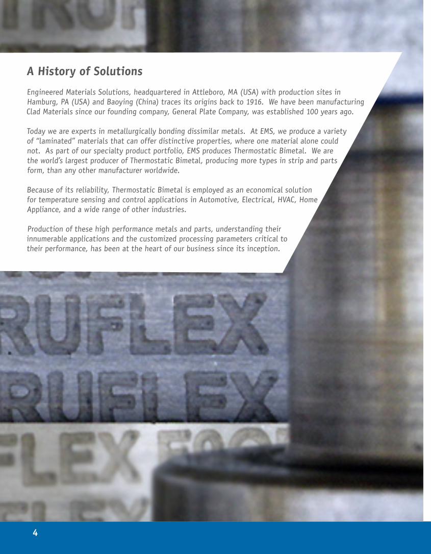
A History of Solutions
Engineered Materials Solutions, headquartered in Attleboro, MA (USA) with production sites in Hamburg, PA (USA) and Baoying (China) traces its origins back to 1916. We have been manufacturing Clad Materials since our founding company, General Plate Company, was established 100 years ago.
Today we are experts in metallurgically bonding dissimilar metals. At EMS, we produce a variety of “laminated” materials that can offer distinctive properties, where one material alone could not. As part of our specialty product portfolio, EMS produces Thermostatic Bimetal. We are the world’s largest producer of Thermostatic Bimetal, producing more types in strip and parts form, than any other manufacturer worldwide.
Because of its reliability, Thermostatic Bimetal is employed as an economical solution for temperature sensing and control applications in Automotive, Electrical, HVAC, Home Appliance, and a wide range of other industries.
Production of these high performance metals and parts, understanding their innumerable applications and the customized processing parameters critical to their performance, has been at the heart of our business since its inception.
5
A History of Solutions
Engineered Materials Solutions, headquartered in Attleboro, MA (USA) with production sites in Hamburg, PA (USA) and Baoying (China) traces its origins back to 1916. We have been manufacturing Clad Materials since our founding company, General Plate Company, was established 100 years ago.
Today we are experts in metallurgically bonding dissimilar metals. At EMS, we produce a variety of “laminated” materials that can offer distinctive properties, where one material alone could not. As part of our specialty product portfolio, EMS produces Thermostatic Bimetal. We are the world’s largest producer of Thermostatic Bimetal, producing more types in strip and parts form, than any other manufacturer worldwide.
Because of its reliability, Thermostatic Bimetal is employed as an economical solution for temperature sensing and control applications in Automotive, Electrical, HVAC, Home Appliance, and a wide range of other industries.
Production of these high performance metals and parts, understanding their innumerable applications and the customized processing parameters critical to their performance, has been at the heart of our business since its inception.
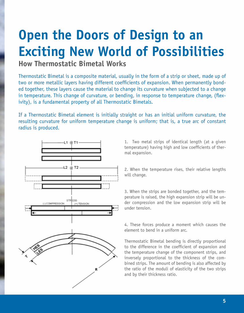
Open the Doors of Design to an Exciting New World of PossibilitiesHow Thermostatic Bimetal WorksThermostatic Bimetal is a composite material, usually in the form of a strip or sheet, made up of two or more metallic layers having different coefficients of expansion. When permanently bond-ed together, these layers cause the material to change its curvature when subjected to a change in temperature. This change of curvature, or bending, in response to temperature change, (flex-ivity), is a fundamental property of all Thermostatic Bimetals.
If a Thermostatic Bimetal element is initially straight or has an initial uniform curvature, the resulting curvature for uniform temperature change is uniform; that is, a true arc of constant radius is produced.
1. Two metal strips of identical length (at a given temperature) having high and low coefficients of ther-mal expansion.
2. When the temperature rises, their relative lengths will change.
3. When the strips are bonded together, and the tem-perature is raised, the high expansion strip will be un-der compression and the low expansion strip will be under tension.
4. These forces produce a moment which causes the element to bend in a uniform arc.
Thermostatic Bimetal bending is directly proportional to the difference in the coefficient of expansion and the temperature change of the component strips, and inversely proportional to the thickness of the com-bined strips. The amount of bending is also affected by the ratio of the moduli of elasticity of the two strips and by their thickness ratio.
6
How It Is MadeA wide variety of alloys are used in the manufacture of Thermostatic Bimetals. The components are joined in a true metallurgical bond made by special techniques. The result is a permanent bond that in many in-stances exceeds the strength of the separate metals.
Truflex™ Thermostatic Bimetals are rolled to finish gauge on precision mills capable of holding very close tolerances. Intermediate annealing operations are performed in continuous strip annealing furnaces in re-ducing atmospheres. Pickling, cleaning, and brushing procedures also play an important part in the ultimate quality achieved.
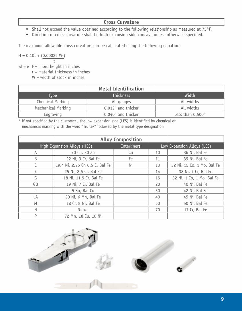
Finishing operations include marking for identification of the material type and/or as identification of the high and low expansion side. The low expansion side is identified as a standard unless otherwise specified by the customer. Finally, the Thermostatic Bimetal is slit and flattened. A cold rolled surface is the standard finish. A uniform matte finish is available as is tension-leveled materials for special applications.
Following these finishing operations, the material undergoes a rigorous inspection to check its physical dimensions, flatness, hardness, electrical resistivity and flexivity.
The EMS Thermostatic Bimetal parts department is equipped with the finest standard and special equipment for producing a variety of parts and assemblies. Spiral and helix coils, flat blades, blanked and pierced mem-bers, U-shapes, and other intricate parts are made with exacting care to customers’ specifications.
7
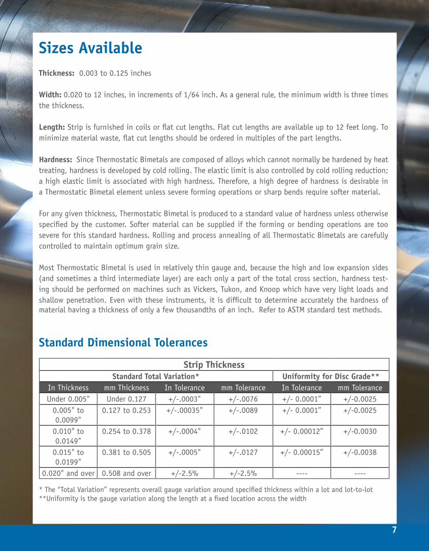
Sizes AvailableThickness: 0.003 to 0.125 inches
Width: 0.020 to 12 inches, in increments of 1/64 inch. As a general rule, the minimum width is three times the thickness.
Length: Strip is furnished in coils or flat cut lengths. Flat cut lengths are available up to 12 feet long. To minimize material waste, flat cut lengths should be ordered in multiples of the part lengths.
Hardness: Since Thermostatic Bimetals are composed of alloys which cannot normally be hardened by heat treating, hardness is developed by cold rolling. The elastic limit is also controlled by cold rolling reduction; a high elastic limit is associated with high hardness. Therefore, a high degree of hardness is desirable in a Thermostatic Bimetal element unless severe forming operations or sharp bends require softer material.
For any given thickness, Thermostatic Bimetal is produced to a standard value of hardness unless otherwise specified by the customer. Softer material can be supplied if the forming or bending operations are too severe for this standard hardness. Rolling and process annealing of all Thermostatic Bimetals are carefully controlled to maintain optimum grain size.
Most Thermostatic Bimetal is used in relatively thin gauge and, because the high and low expansion sides (and sometimes a third intermediate layer) are each only a part of the total cross section, hardness test-ing should be performed on machines such as Vickers, Tukon, and Knoop which have very light loads and shallow penetration. Even with these instruments, it is difficult to determine accurately the hardness of material having a thickness of only a few thousandths of an inch. Refer to ASTM standard test methods.
Standard Dimensional Tolerances
Strip ThicknessStandard Total Variation* Uniformity for Disc Grade**
In Thickness mm Thickness In Tolerance mm Tolerance In Tolerance mm ToleranceUnder 0.005" Under 0.127 +/-.0003" +/-.0076 +/- 0.0001” +/-0.0025
0.005" to 0.0099"
0.127 to 0.253 +/-.00035" +/-.0089 +/- 0.0001” +/-0.0025
0.010" to 0.0149"
0.254 to 0.378 +/-.0004" +/-.0102 +/- 0.00012” +/-0.0030
0.015" to 0.0199"
0.381 to 0.505 +/-.0005" +/-.0127 +/- 0.00015” +/-0.0038
0.020" and over 0.508 and over +/-2.5% +/-2.5% ---- ----
* The “Total Variation” represents overall gauge variation around specified thickness within a lot and lot-to-lot**Uniformity is the gauge variation along the length at a fixed location across the width
8
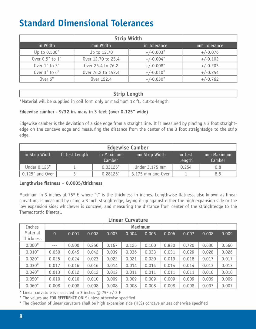
Standard Dimensional TolerancesStrip Width
in Width mm Width in Tolerance mm ToleranceUp to 0.500" Up to 12.70 +/-0.003" +/-0.076
Over 0.5" to 1" Over 12.70 to 25.4 +/-0.004" +/-0.102Over 1" to 3" Over 25.4 to 76.2 +/-0.008" +/-0.203Over 3" to 6" Over 76.2 to 152.4 +/-0.010" +/-0.254
Over 6" Over 152.4 +/-0.030" +/-0.762
Strip Length*Material will be supplied in coil form only or maximum 12 ft. cut-to-length
Edgewise camber - 9/32 in. max. in 3 feet (over 0.125” wide)
Edgewise camber is the deviation of a side edge from a straight line. It is measured by placing a 3 foot straight-edge on the concave edge and measuring the distance from the center of the 3 foot straightedge to the strip edge.
Edgewise Camberin Strip Width ft Test Length in Maximum
Cambermm Strip Width m Test
Lengthmm Maximum
CamberUnder 0.125" 1 0.03125" Under 3.175 mm 0.254 0.8
0.125" and Over 3 0.28125" 3.175 mm and Over 1 8.5
Lengthwise flatness = 0.0005/thickness
Maximum in 3 inches at 75º F, where “t” is the thickness in inches. Lengthwise flatness, also known as linear curvature, is measured by using a 3 inch straightedge, laying it up against either the high expansion side or the low expansion side; whichever is concave, and measuring the distance from center of the straightedge to the Thermostatic Bimetal.
Linear CurvatureInches Material
Thickness
Maximum0 0.001 0.002 0.003 0.004 0.005 0.006 0.007 0.008 0.009
0.000" --- 0.500 0.250 0.167 0.125 0.100 0.830 0.720 0.630 0.5600.010" 0.050 0.045 0.042 0.039 0.036 0.033 0.031 0.029 0.028 0.0260.020" 0.025 0.024 0.023 0.022 0.021 0.020 0.019 0.018 0.017 0.0170.030" 0.017 0.016 0.016 0.014 0.014 0.014 0.014 0.014 0.013 0.0130.040" 0.013 0.012 0.012 0.012 0.011 0.011 0.011 0.011 0.010 0.0100.050" 0.010 0.010 0.010 0.009 0.009 0.009 0.009 0.009 0.009 0.0090.060" 0.008 0.008 0.008 0.008 0.008 0.008 0.008 0.008 0.007 0.007
* Linear curvature is measured in 3 inches @ 75F +/-2 F* The values are FOR REFERENCE ONLY unless otherwise specified * The direction of linear curvature shall be high expansion side (HES) concave unless otherwise specified
9
Cross Curvature• Shall not exceed the value obtained according to the following relationship as measured at 75°F.• Direction of cross curvature shall be high expansion side concave unless otherwise specified.
The maximum allowable cross curvature can be calculated using the following equation:
H = 0.10t + (0.00025 W2) twhere H= chord height in inches t = material thickness in inches W = width of stock in inches
Metal IdentificationType Thickness Width
Chemical Marking All gauges All widthsMechanical Marking 0.012" and thicker All widths
Engraving 0.040" and thicker Less than 0.500"* If not specified by the customer , the low expansion side (LES) is identified by chemical or mechanical marking with the word “Truflex” followed by the metal type designation
Alloy CompositionHigh Expansion Alloys (HES) Interliners Low Expansion Alloys (LES)
A 70 Cu, 30 Zn Cu 10 36 Ni, Bal FeB 22 Ni, 3 Cr, Bal Fe Fe 11 39 Ni, Bal FeC 19.4 Ni, 2.25 Cr, 0.5 C, Bal Fe Ni 13 32 Ni, 15 Co, 1 Mo, Bal FeE 25 Ni, 8.5 Cr, Bal Fe 14 38 Ni, 7 Cr, Bal FeG 18 Ni, 11.5 Cr, Bal Fe 15 32 Ni, 1 Co, 1 Mo, Bal FeGB 19 Ni, 7 Cr, Bal Fe 20 40 Ni, Bal FeJ 5 Sn, Bal Cu 30 42 Ni, Bal FeLA 20 Ni, 6 Mn, Bal Fe 40 45 Ni, Bal FeM 18 Cr, 8 Ni, Bal Fe 50 50 Ni, Bal FeN Nickel 70 17 Cr, Bal FeP 72 Mn, 18 Cu, 10 Ni
10
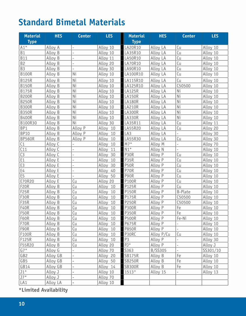
Standard Bimetal MaterialsMaterial
TypeHES Center LES Material
TypeHES Center LES
A1* Alloy A - Alloy 10 LA20R10 Alloy LA Cu Alloy 10B1 Alloy B - Alloy 10 LA35R10 Alloy LA Cu Alloy 10B11 Alloy B - Alloy 11 LA50R10 Alloy LA Cu Alloy 10B2 Alloy B - Alloy 20 LA70R10 Alloy LA Cu Alloy 10B3 Alloy B - Alloy 30 LA90R10 Alloy LA Cu Alloy 10B100R Alloy B Ni Alloy 10 LA100R10 Alloy LA Cu Alloy 10B125R Alloy B Ni Alloy 10 LA115R10 Alloy LA Cu Alloy 10B150R Alloy B Ni Alloy 10 LA125R10 Alloy LA C50500 Alloy 10B175R Alloy B Ni Alloy 10 LA125R Alloy LA Ni Alloy 10B200R Alloy B Ni Alloy 10 LA150R Alloy LA Ni Alloy 10B250R Alloy B Ni Alloy 10 LA180R Alloy LA Ni Alloy 10B300R Alloy B Ni Alloy 10 LA210R Alloy LA Ni Alloy 10B350R Alloy B Ni Alloy 10 LA300R Alloy LA Ni Alloy 10B400R Alloy B Ni Alloy 10 LA330R Alloy LA Ni Alloy 10B100R30 Alloy B Ni Alloy 30 LA35R11 Alloy LA Cu Alloy 11BP1 Alloy B Alloy P Alloy 10 LA55R20 Alloy LA Cu Alloy 20BP10 Alloy B Alloy P Alloy 10 LA3 Alloy LA - Alloy 30BP560R Alloy B Alloy P Alloy 10 LA55R30 Alloy LA Cu Alloy 30C1 Alloy C - Alloy 10 M7* Alloy M - Alloy 70C11 Alloy C - Alloy 11 N1* Alloy N - Alloy 10C3 Alloy C - Alloy 30 P30R Alloy P Cu Alloy 10E1 Alloy E - Alloy 10 P35R Alloy P Cu Alloy 10E3 Alloy E - Alloy 30 P50R Alloy P Cu Alloy 10E4 Alloy E - Alloy 40 P70R Alloy P Cu Alloy 10E5 Alloy E - Alloy 50 P90R Alloy P Cu Alloy 10E70R20 Alloy E Cu Alloy 20 P100R Alloy P Cu Alloy 10F20R Alloy B Cu Alloy 10 P125R Alloy P Cu Alloy 10F25R Alloy B Cu Alloy 10 P150R Alloy P B-Plate Alloy 10F30R Alloy B Cu Alloy 10 P175R Alloy P C50500 Alloy 10F35R Alloy B Cu Alloy 10 P250R Alloy P C50500 Alloy 10F40R Alloy B Cu Alloy 10 P300R Alloy P Fe Alloy 10F50R Alloy B Cu Alloy 10 P350R Alloy P Fe Alloy 10F60R Alloy B Cu Alloy 10 P500R Alloy P Fe-Ni Alloy 10F70R Alloy B Cu Alloy 10 P675R Alloy P - Alloy 10F90R Alloy B Cu Alloy 10 P850R Alloy P - Alloy 10F100R Alloy B Cu Alloy 10 P30RC Alloy P/Cu Cu Alloy 10F125R Alloy B Cu Alloy 10 P3 Alloy P - Alloy 30F55R20 Alloy B Cu Alloy 20 PJ* Alloy P - Alloy JG7* Alloy G - Alloy 70 S363 B/SS305 - SS301/10GB2 Alloy GB - Alloy 20 SB175R Alloy B Fe Alloy 10GB5 Alloy GB - Alloy 50 SB250R Alloy B Fe Alloy 10GB14 Alloy GB - Alloy 14 SB300R Alloy B Fe Alloy 10J1* Alloy J - Alloy 10 1513* Alloy 15 - Alloy 13J7* Alloy J - Alloy 70LA1 Alloy LA - Alloy 10
*Limited Availability
11
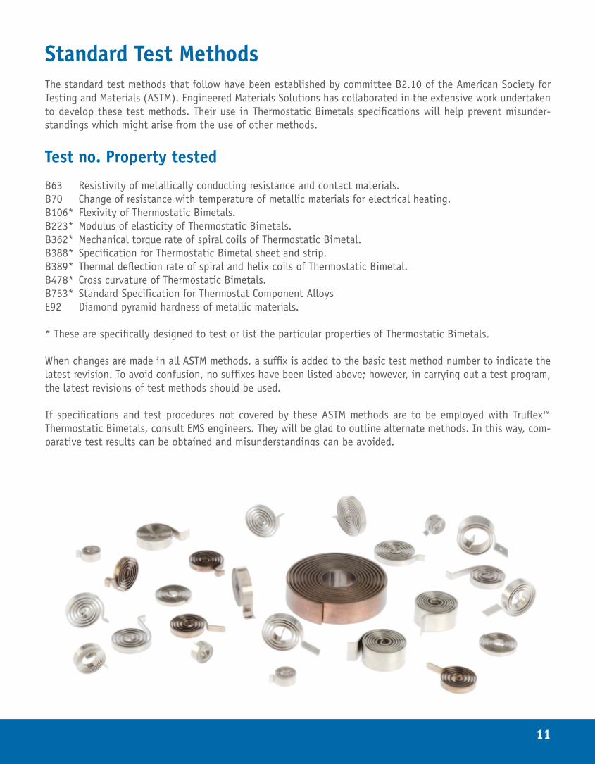
Standard Test MethodsThe standard test methods that follow have been established by committee B2.10 of the American Society for Testing and Materials (ASTM). Engineered Materials Solutions has collaborated in the extensive work undertaken to develop these test methods. Their use in Thermostatic Bimetals specifications will help prevent misunder-standings which might arise from the use of other methods.
Test no. Property tested
B63 Resistivity of metallically conducting resistance and contact materials.B70 Change of resistance with temperature of metallic materials for electrical heating.B106* Flexivity of Thermostatic Bimetals.B223* Modulus of elasticity of Thermostatic Bimetals.B362* Mechanical torque rate of spiral coils of Thermostatic Bimetal.B388* Specification for Thermostatic Bimetal sheet and strip.B389* Thermal deflection rate of spiral and helix coils of Thermostatic Bimetal.B478* Cross curvature of Thermostatic Bimetals.B753* Standard Specification for Thermostat Component AlloysE92 Diamond pyramid hardness of metallic materials.
* These are specifically designed to test or list the particular properties of Thermostatic Bimetals.
When changes are made in all ASTM methods, a suffix is added to the basic test method number to indicate the latest revision. To avoid confusion, no suffixes have been listed above; however, in carrying out a test program, the latest revisions of test methods should be used.
If specifications and test procedures not covered by these ASTM methods are to be employed with Truflex™ Thermostatic Bimetals, consult EMS engineers. They will be glad to outline alternate methods. In this way, com-parative test results can be obtained and misunderstandings can be avoided.

12
BASIC THEORY & FUNDAMENTAL CALCULATIONSRADIUS OF CURVATURE
The following equation describes the flexing of a two-component Thermostatic Bimetal strip:
whereα1 and α2 = temperature coefficients of expansion (expansivities)E1 and E2 = moduli of elasticityt1 and t2 = thickness of components t = thickness of strip ρ = radius of curvature of stripT0 and T1 = temperatures m = t1/t2
n = E1/E2
If the thicknesses of both materials are the same,t1 = t2 therefore m = 1
then
Further, if the moduli of elasticity are the same,E1 = E2 n = 1
then
1
2
3
13
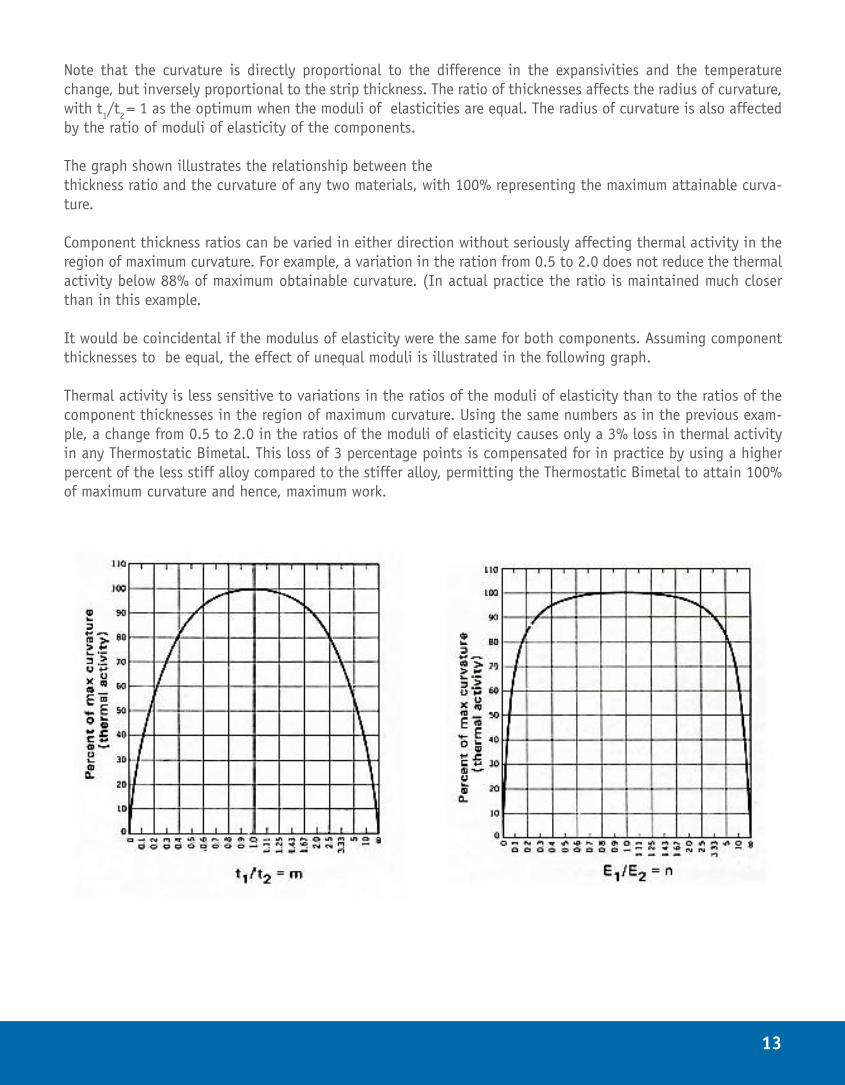
Note that the curvature is directly proportional to the difference in the expansivities and the temperature change, but inversely proportional to the strip thickness. The ratio of thicknesses affects the radius of curvature, with t1/t2 = 1 as the optimum when the moduli of elasticities are equal. The radius of curvature is also affected by the ratio of moduli of elasticity of the components.
The graph shown illustrates the relationship between the thickness ratio and the curvature of any two materials, with 100% representing the maximum attainable curva-ture.
Component thickness ratios can be varied in either direction without seriously affecting thermal activity in the region of maximum curvature. For example, a variation in the ration from 0.5 to 2.0 does not reduce the thermal activity below 88% of maximum obtainable curvature. (In actual practice the ratio is maintained much closer than in this example.
It would be coincidental if the modulus of elasticity were the same for both components. Assuming component thicknesses to be equal, the effect of unequal moduli is illustrated in the following graph.
Thermal activity is less sensitive to variations in the ratios of the moduli of elasticity than to the ratios of the component thicknesses in the region of maximum curvature. Using the same numbers as in the previous exam-ple, a change from 0.5 to 2.0 in the ratios of the moduli of elasticity causes only a 3% loss in thermal activity in any Thermostatic Bimetal. This loss of 3 percentage points is compensated for in practice by using a higher percent of the less stiff alloy compared to the stiffer alloy, permitting the Thermostatic Bimetal to attain 100% of maximum curvature and hence, maximum work.
14
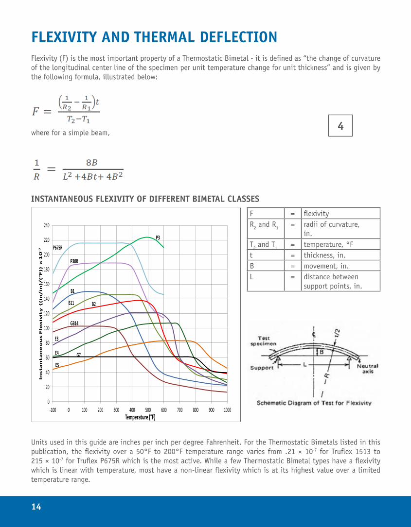
FLEXIVITY AND THERMAL DEFLECTIONFlexivity (F) is the most important property of a Thermostatic Bimetal - it is defined as “the change of curvature of the longitudinal center line of the specimen per unit temperature change for unit thickness” and is given by the following formula, illustrated below:
where for a simple beam,
INSTANTANEOUS FLEXIVITY OF DIFFERENT BIMETAL CLASSES
0
20
40
60
80
100
120
140
160
180
200
220
240
-100 0 100 200 300 400 500 600 700 800 900 1000
Insta
nta
ne
ou
s F
lex
ivit
y {(i
n/in
)/(°
F)}
x
10
-7
Temperature (°F)
P3
P675R
P30R
B1
B11 B2
E3
GB14
E4
E5
G7
F = flexivityR2 and R1 = radii of curvature,
in.T2 and T1 = temperature, °Ft = thickness, in.B = movement, in.L = distance between
support points, in.
4
Units used in this guide are inches per inch per degree Fahrenheit. For the Thermostatic Bimetals listed in this publication, the flexivity over a 50°F to 200°F temperature range varies from .21 × 10-7 for Truflex 1513 to 215 × 10-7 for Truflex P675R which is the most active. While a few Thermostatic Bimetal types have a flexivity which is linear with temperature, most have a non-linear flexivity which is at its highest value over a limited temperature range.
15
The table of mechanical and physical properties (pp 24-26) gives the flexivity over a 50°F to 200°F temperature range, (Engineered Materials Solutions standard test range). In addition, the table on page 47 lists the instanta-neous flexivities at twenty different temperatures from -100°F to +1000°F for all Thermostatic Bimetal types in-cluded in this publication. This table enables the determination of the average flexivity value over any required temperature range. Instantaneous Flexivity versus temperature is plotted above for different Bimetal classes.
THE EFFECT OF FLEXIVITY TEMPERATURE DEPENDENCE ON MATERIAL SELECTION
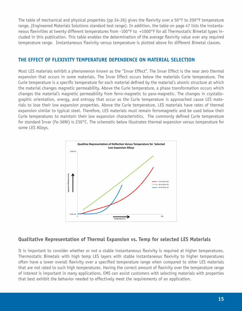
Most LES materials exhibit a phenomenon known as the “Invar Effect”. The Invar Effect is the near zero thermal expansion that occurs in some materials. The Invar Effect occurs below the materials Curie temperature. The Curie temperature is a specific temperature for each material defined by the material’s atomic structure at which the material changes magnetic permeability. Above the Curie temperature, a phase transformation occurs which changes the material’s magnetic permeability from ferro-magnetic to para-magnetic. The changes in crystallo-graphic orientation, energy, and entropy that occur as the Curie temperature is approached cause LES mate-rials to lose their low expansion properties. Above the Curie temperature, LES materials have rates of thermal expansion similar to typical steel. Therefore, LES materials must remain ferromagnetic and be used below their Curie temperatures to maintain their low expansion characteristics. The commonly defined Curie temperature for standard Invar (Fe-36Ni) is 230°C. The schematic below illustrates thermal expansion versus temperature for some LES Alloys.
0.00E+00
5.00E+03
0 600
Expa
nsio
n PP
M (∆
mm
/mm
)
Temperatuer (C )
Qualitive Representation of Deflection Versus Temperature for Selected Low Expansion Alloys
Fe - 42 Ni (Alloy 30)
Fe - 49 Ni (Alloy 50)
Fe - 36 Ni (Alloy 10)
Qualitative Representation of Thermal Expansion vs. Temp for selected LES Materials
It is important to consider whether or not a stable instantaneous flexivity is required at higher temperatures. Thermostatic Bimetals with high temp LES layers with stable instantaneous flexivity to higher temperatures often have a lower overall flexivity over a specified temperature range when compared to other LES materials that are not rated to such high temperatures. Having the correct amount of flexivity over the temperature range of interest is important in many applications. EMS can assist customers with selecting materials with properties that best exhibit the behavior needed to effectively meet the requirements of an application.
16
Modulus of Elasticity in Bending Modulus of elasticity in bending (Ebending) is a measure of the force required to bend a material within its elas-
tic bending limit. The higher the modulus, the greater the force required. All formulas for mechanical force on
any member in bending, (regardless of shape), include the modulus of elasticity (E). The modulus of elasticity
for the eighty-nine types of Thermostatic Bimetal materials in this publication range from 17 Msi for Truflex
PJ to 27.5 Msi for Truflex B100R.
While the modulus of elasticity changes somewhat with temperature, the variation in Thermostatic Bimetals
is marginal and therefore only room temperature values are published. For most Thermostatic Bimetals, the
modulus of elasticity is relatively constant with increasing temperature due the fact the low expansion side
has an increasing modulus (due to Invar effect) while the high expansion side has a decreasing modulus.
The bending modulus of composite materials increases the complexity of calculations due to the fact that the
effect of each of the component materials on the bulk material must be considered. This can be done by using
mechanics of materials to find the modular ratio. (Philpot, 2011) The modulus of elasticity of a composite
Thermostatic Bimetal may be calculated from the moduli of elasticity and the thicknesses of its components.
The equation historically used to calculate the elastic modulus in bending of a two layer Thermostatic Bimetal
material system is shown below. (Savolainen and Sears, 1969)
17
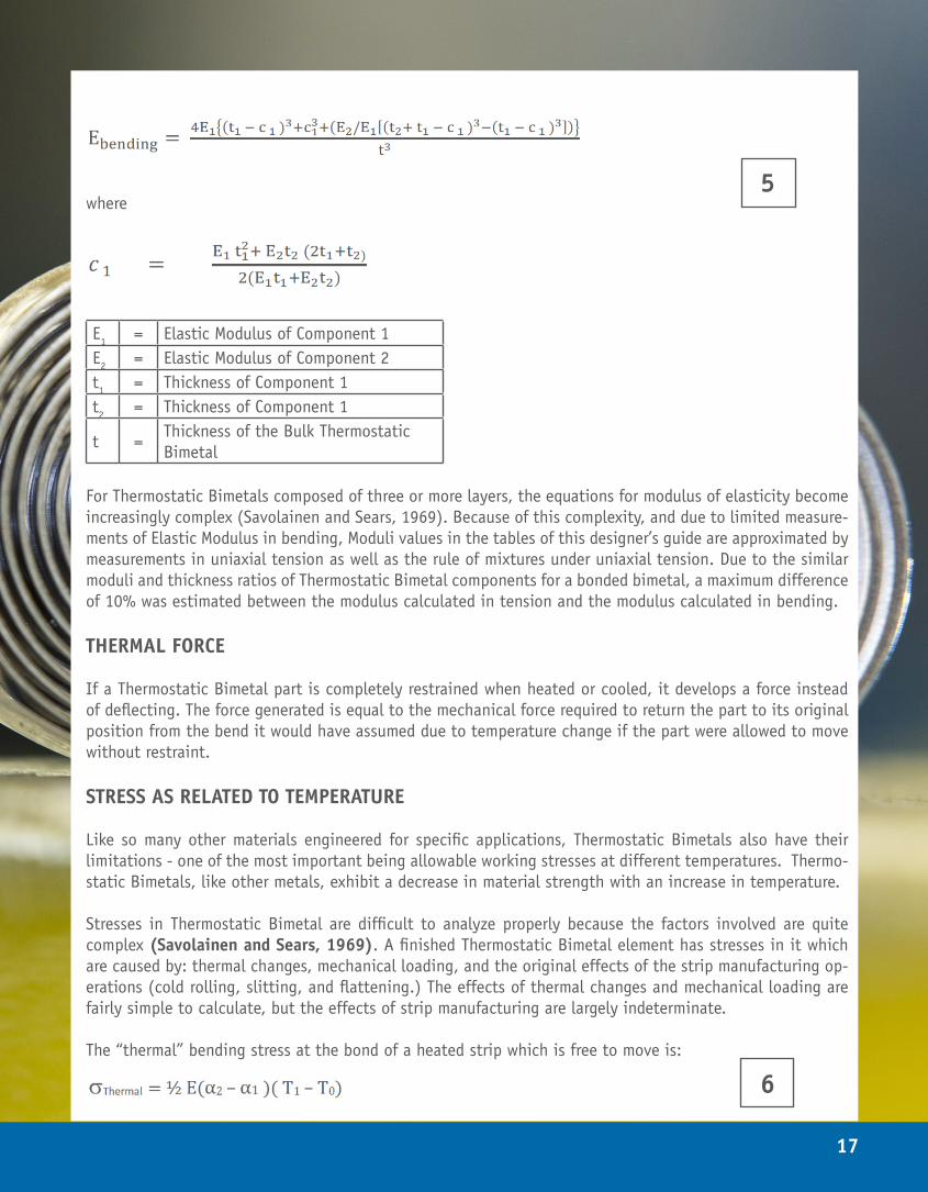
where
E1 = Elastic Modulus of Component 1E2 = Elastic Modulus of Component 2t1 = Thickness of Component 1t2 = Thickness of Component 1
t =Thickness of the Bulk Thermostatic Bimetal
For Thermostatic Bimetals composed of three or more layers, the equations for modulus of elasticity become increasingly complex (Savolainen and Sears, 1969). Because of this complexity, and due to limited measure-ments of Elastic Modulus in bending, Moduli values in the tables of this designer’s guide are approximated by measurements in uniaxial tension as well as the rule of mixtures under uniaxial tension. Due to the similar moduli and thickness ratios of Thermostatic Bimetal components for a bonded bimetal, a maximum difference of 10% was estimated between the modulus calculated in tension and the modulus calculated in bending.
THERMAL FORCE
If a Thermostatic Bimetal part is completely restrained when heated or cooled, it develops a force instead of deflecting. The force generated is equal to the mechanical force required to return the part to its original position from the bend it would have assumed due to temperature change if the part were allowed to move without restraint.
STRESS AS RELATED TO TEMPERATURE
Like so many other materials engineered for specific applications, Thermostatic Bimetals also have their limitations - one of the most important being allowable working stresses at different temperatures. Thermo-static Bimetals, like other metals, exhibit a decrease in material strength with an increase in temperature.
Stresses in Thermostatic Bimetal are difficult to analyze properly because the factors involved are quite complex (Savolainen and Sears, 1969). A finished Thermostatic Bimetal element has stresses in it which are caused by: thermal changes, mechanical loading, and the original effects of the strip manufacturing op-erations (cold rolling, slitting, and flattening.) The effects of thermal changes and mechanical loading are fairly simple to calculate, but the effects of strip manufacturing are largely indeterminate.
The “thermal” bending stress at the bond of a heated strip which is free to move is:
5
6
18
With the low expansive component in tension and the high expansive component in compression. The outer fiber stresses for both components are one half the bond stresses, with the low expansive component in compression and the high expansive component in tension. Zero stresses occur one-sixth of the total thickness in from the outer surfaces.
Uniform heating and uniform restraining of the strip results in “mechanical” bending stress of:
With the low expansive component in tension and the high expansive component in compression. In this in-stance, the stress is uniform through-out the total thickness of the strip. These stresses are the same as the bond stresses of a freely deflecting strip. If a straight cantilever strip of Thermostatic Bimetal is heated with the free end restrained in its original position, the mechanical restraint and the stresses due to heating reach maximum at or near the point of clamping. The following equation gives the maximum stresses which are at the outer fibers (Savolainen and Sears, 1969):
However, the bond stresses remain the same as the bond stresses in either a freely deflecting or uniformly re-strained strip. A straight cantilever strip with uniform cross-section is not efficient since it is worked at full capacity only at the clamped end. One approach to maximize work for a minimum volume of bimetal is to employ a tapered beam, as either a triangular element or a trapezoidal element, with the larger width at the clamped end (Sears, 1958).
Equations (6), (7), and (8), which are used to determine thermo-mechanical stresses, assume the internal stress-es to be zero, and this is not necessarily the case. For these reasons, high safety factors must be used to figure allowable stresses after the simple thermal and mechanical stresses have been calculated. Elements should also be life tested.
For applications where there is no restraint of the Thermostatic Bimetal, the maximum temperature each material can withstand for brief periods is indicated in the table of properties on page 22. This figure will be lower if exposure time is long and the allowable amount of calibration change is very small. Therefore, it is best to make actual tests on samples before making a final production run.
For applications where the Thermostatic Bimetal is partially or completely re-strained from motion, it is prefer-able to have load decrease with an increase in temperature. If load must increase with temperature, it is best to keep the load under that which would be equivalent to approximately 100°F of restraint. In applications involving re-strained parts, it is advisable to make samples for testing before proceeding with production.
7
8
19
ELECTRICAL RESISTIVITY AND RESISTIVE HEATINGA variety of Thermostatic Bimetals covering a wide range of electrical resistivities are used in applications in which heat is generated by passing an electric current through the Thermostatic Bimetal. Different ratings can also be obtained by varying the thickness and width of one type of Thermostatic Bimetal.
The relation between resistivity and resistance in rectangular Thermostatic Bimetal elements is given by the following formula:
where:
ρ = resistivity of Thermostatic Bimetal in (ohms mm2/m or µohms-m) R = resistance in ohms.A = cross sectional area in mm2.w = width in mm.t = thickness in mm.L = length in meters.
Or in English units as:
where:
ρ = resistivity of Thermostatic Bimetal in (ohms circular mil per foot) R = resistance in ohms.w = width in inches.t = thickness in inches.L = length in inches.
Example: A strip of P850R Thermostatic Bimetal 0.030 inches by 0.500 inches by 15.6 inches long between points of electrical contact and having an electrical resistivity of 850 ohms per cmf is used. Find the resistance of the strip.
EMS has designed four series of controlled electrical resistivity Thermostatic Bimetals (FR’s, BR’s, LAR’s, and PR’s) to fill the need of circuit breaker manufacturers who have found it desirable to make a line of breakers using bimetal elements of the same physical size with varying current carrying abilities. This design incorporates a shunt layer of an appropriate electrically-conductive alloy between the high and low expansive components to control the resistivity.
9
10
20
The calculation for resistivity is relatively simple if the three components are considered as a parallel circuit:
where
= Thickness fraction (versus total thickness of three) for components 1, 2, and 3= resistivity of the three components= resistivity of the bonded Thermostatic Bimetal
Through the use of Joule’s First Law and the definition of Specific Heat Capacity, it is possible to derive an ideal temperature rise in a bimetal where convection and radiation heat losses are considered negligible.
From Joule’s First Law, an electric current has a heating effect of:
Q = I2 Rᶿ where
Q = heat in calories, R = resistance in ohms, I = current in amperes, ᶿ = time in seconds
The relationship between this Joule heating and the temperature rise is given by:
Q = c m (∆T)
where c = specific heat capacity in J/(g °C), m = mass in g, ∆T = temperature rise in °C
Therefore, the temperature rise of a resistor (disregarding convection and radiation heat losses) is given by:
Substituting for R using Equation (9), and assuming a rectangular cross section, formula 13 can be expressed as:
11
12
13
14
21
where∆T = temperature rise in °Cı = current in amperesρ = electrical resistivity in µohms-mᶿ = time in secc = specific heat capacity in J/(g °C), estimated at 0.502 for all Bimetals.d = density in g/cm3, or mass divided by volume (wtL) w = width in mmt = total thickness in mm
A similar equation can be derived in English units utilizing available conversion factors from these metric quan-tities.
Given the approximate nature of Equation (14), the most critical observation is that the heating effect is pro-portional to ı2 ρ in which ı2 is analogous to the current rating of a breaker and ρ is analogous to the electrical resistivity of the Thermostatic Bimetal. Throughout a line of circuit breakers, ı2 ρ must be fairly constant for uniform tripping time. Therefore, the series of Thermostatic Bimetals must vary in electrical resistivity as the square of the rating. The previous equation is useful in laying out a line of breakers since, after the type of mate-rial has been experimentally determined for one rating, the others can be approximately calculated for the same thickness and width of the breaker. Further, Equation (14) shows that temperature rise is inversely proportional to the squares of both the thickness and width.
Equation (14) will also assist in determining whether EMS resistive series materials available are sufficient for the range of current ratings within a designed line of breakers. If the range of resistive materials is not suffi-cient, thickness or width changes may be required.
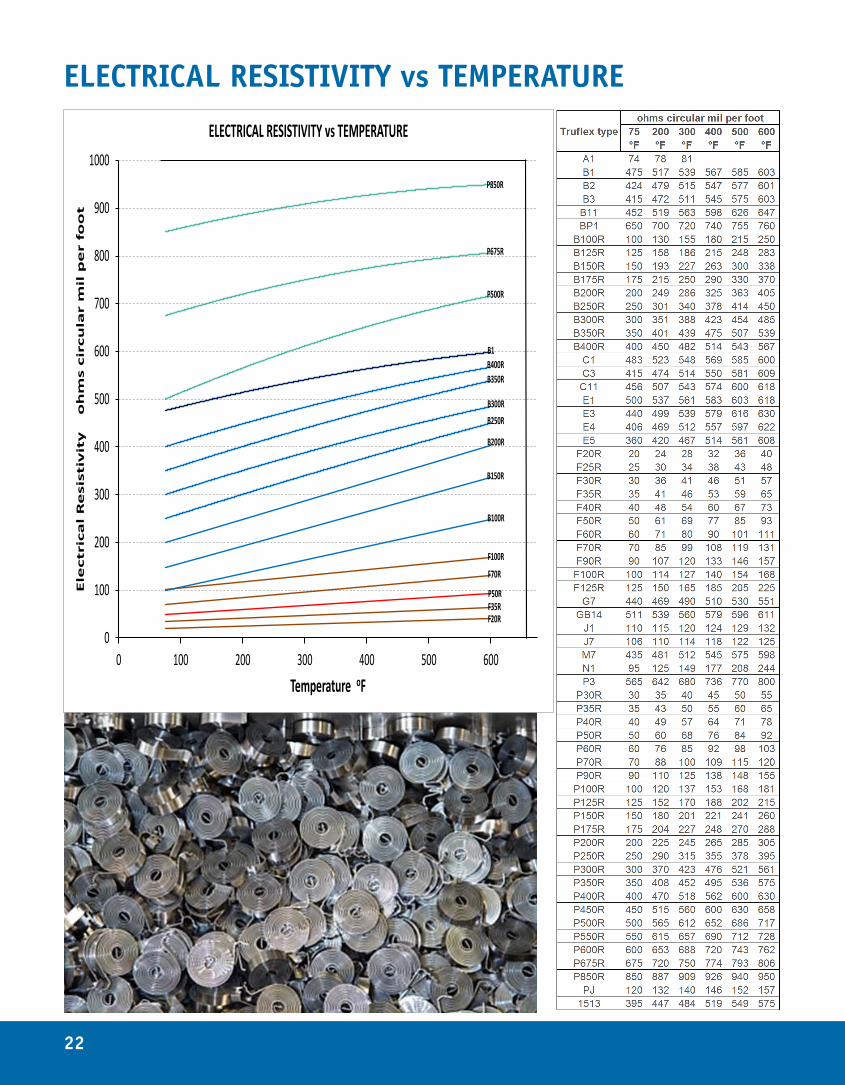
22
0
100
200
300
400
500
600
700
800
900
1000
0 100 200 300 400 500 600
Ele
ctr
ica
l R
esis
tiv
ity
o
hm
s c
ircu
lar
mil
pe
r fo
ot
Temperature oF
ELECTRICAL RESISTIVITY vs TEMPERATURE
B350R
F20RF35R
P850R
P675R
P500R
B400R
B300RB250R
B200R
B150R
B100R
F100R
F70R
P50R
B1
ELECTRICAL RESISTIVITY vs TEMPERATURE
23
STABILIZING HEAT TREATMENTBecause of residual stresses which build up in Thermostatic Bimetals during rolling, slitting, straightening, cut-ting and forming operations, parts made from Thermostatic Bimetal are commonly heat treated before assembly into a final product. Heat treating relieves or redistributes these stresses to maintain stability, accuracy and uniformity of operation of the part which otherwise will go out of calibration either when the temperature is increased or time has elapsed.
Heat treating is performed in either an air or inert atmosphere furnace. During the heat treating process, the parts must be free to deflect to ensure uniform heat treatment between parts within a lot. Heat treatment tem-peratures should be at least 50 °F above the maximum temperature encountered in operation or in processing after assembly. A minimum of 400°F for one hour is recommended for most Thermostatic Bimetals.
Since heat treating is not an annealing or normalizing process, it has only a minor effect on the physical prop-erties of Thermostatic Bimetal. Recommended heat treatment will cause no change in hardness and only slight changes in temperature deflection rate and mechanical force rate. However, the change in shape which results from heat treatment should be considered when fabricating a part, so that compensation can be made for this change.
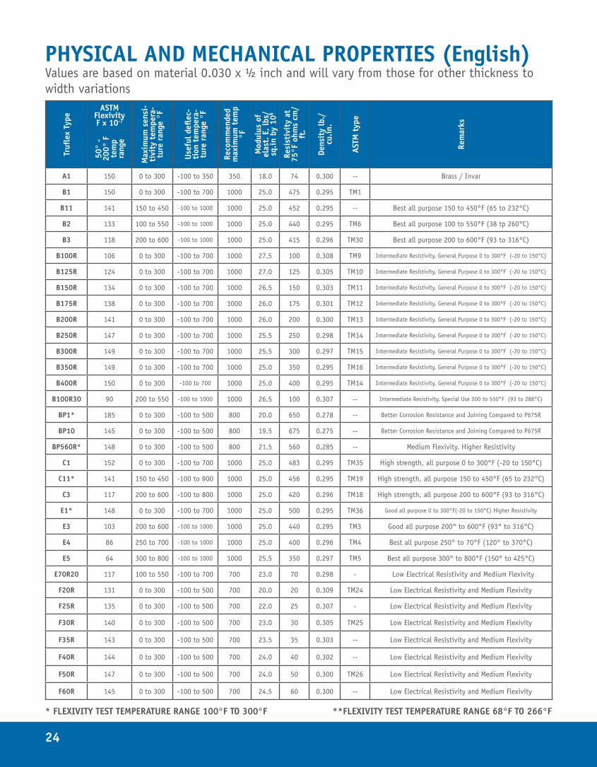
When heat treated, a formed part tends to revert to its original shape because some of the stresses caused in forming the part have been relieved. A blade which is flat prior to heat treatment will assume a curvature after heat treating with the high expansive side becoming concave. Strip material can be pre-curved (in a direction opposite to the curvature caused by heat treatment) by a roller flattener ahead of the press. The opposition of these two curvatures will result in the desired flatness or curvature of the finished blade.
Usually simple heat treating is all that is necessary for most parts and is satisfactory even if the parts are ad-justed slightly after heat treatment. However, for cases where stability is critical, such as in room Thermostats, the parts or the whole assembly should be heat treated again after any mechanical adjustment. The best meth-od is not to calibrate the part, but rather some other component of the device, such as the part on which the Thermostatic Bimetal is mounted.
In some cases, where the Thermostatic Bimetal parts must operate under restraint, strength may be materially increased by heat treating under similar restraint.
24
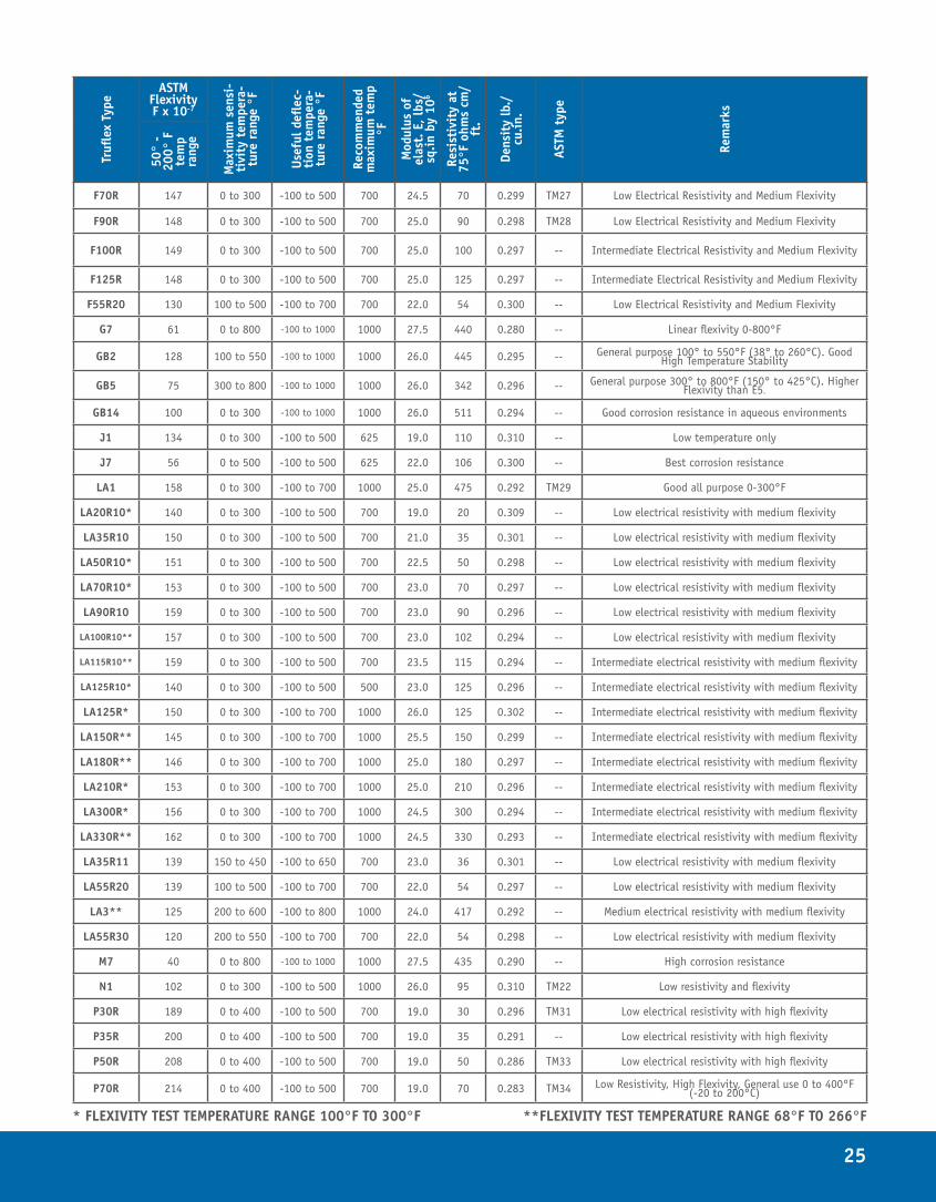
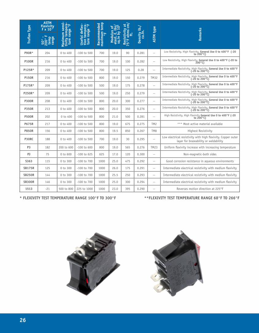
PHYSICAL AND MECHANICAL PROPERTIES (English)Values are based on material 0.030 x ½ inch and will vary from those for other thickness to width variations
Trufl
ex T
ype
ASTM Flexivity F x 10-7
Max
imum
sen
si-
tivi
ty t
empe
ra-
ture
ran
ge °
F
Usef
ul d
eflec
-ti
on t
empe
ra-
ture
ran
ge °
F
Reco
mm
ende
d m
axim
um t
emp
°F
Mod
ulus
of
elas
t. E
, lbs
/sq
.in b
y 10
6
Resi
stiv
ity
at
75°F
ohm
s cm
/ft
.
Dens
ity
lb./
cu.in
.
ASTM
typ
e
Rem
arks
50°
- 20
0° F
te
mp
rang
e
A1 150 0 to 300 -100 to 350 350 18.0 74 0.300 -- Brass / Invar
B1 150 0 to 300 -100 to 700 1000 25.0 475 0.295 TM1
B11 141 150 to 450 -100 to 1000 1000 25.0 452 0.295 -- Best all purpose 150 to 450°F (65 to 232°C)
B2 133 100 to 550 -100 to 1000 1000 25.0 440 0.295 TM6 Best all purpose 100 to 550°F (38 tp 260°C)
B3 118 200 to 600 -100 to 1000 1000 25.0 415 0.296 TM30 Best all purpose 200 to 600°F (93 to 316°C)
B100R 106 0 to 300 -100 to 700 1000 27.5 100 0.308 TM9 Intermediate Resistivity, General Purpose 0 to 300°F (-20 to 150°C)
B125R 124 0 to 300 -100 to 700 1000 27.0 125 0.305 TM10 Intermediate Resistivity, General Purpose 0 to 300°F (-20 to 150°C)
B150R 134 0 to 300 -100 to 700 1000 26.5 150 0.303 TM11 Intermediate Resistivity, General Purpose 0 to 300°F (-20 to 150°C)
B175R 138 0 to 300 -100 to 700 1000 26.0 175 0.301 TM12 Intermediate Resistivity, General Purpose 0 to 300°F (-20 to 150°C)
B200R 141 0 to 300 -100 to 700 1000 26.0 200 0.300 TM13 Intermediate Resistivity, General Purpose 0 to 300°F (-20 to 150°C)
B250R 147 0 to 300 -100 to 700 1000 25.5 250 0.298 TM14 Intermediate Resistivity, General Purpose 0 to 300°F (-20 to 150°C)
B300R 149 0 to 300 -100 to 700 1000 25.5 300 0.297 TM15 Intermediate Resistivity, General Purpose 0 to 300°F (-20 to 150°C)
B350R 149 0 to 300 -100 to 700 1000 25.0 350 0.295 TM16 Intermediate Resistivity, General Purpose 0 to 300°F (-20 to 150°C)
B400R 150 0 to 300 -100 to 700 1000 25.0 400 0.295 TM14 Intermediate Resistivity, General Purpose 0 to 300°F (-20 to 150°C)
B100R30 90 200 to 550 -100 to 1000 1000 26.5 100 0.307 -- Intermediate Resistivity, Special Use 200 to 550°F (93 to 288°C)
BP1* 185 0 to 300 -100 to 500 800 20.0 650 0.278 -- Better Corrosion Resistance and Joining Compared to P675R
BP10 145 0 to 300 -100 to 500 800 19.5 675 0.275 -- Better Corrosion Resistance and Joining Compared to P675R
BP560R* 148 0 to 300 -100 to 500 800 21.5 560 0.285 -- Medium Flexivity. Higher Resistivity
C1 152 0 to 300 -100 to 700 1000 25.0 483 0.295 TM35 High strength, all purpose 0 to 300°F (-20 to 150°C)
C11* 141 150 to 450 -100 to 900 1000 25.0 456 0.295 TM19 High strength, all purpose 150 to 450°F (65 to 232°C)
C3 117 200 to 600 -100 to 800 1000 25.0 420 0.296 TM18 High strength, all purpose 200 to 600°F (93 to 316°C)
E1* 148 0 to 300 -100 to 700 1000 25.0 500 0.295 TM36 Good all purpose 0 to 300°F(-20 to 150°C) Higher Resistivity
E3 103 200 to 600 -100 to 1000 1000 25.0 440 0.295 TM3 Good all purpose 200° to 600°F (93° to 316°C)
E4 86 250 to 700 -100 to 1000 1000 25.0 400 0.296 TM4 Best all purpose 250° to 70°F (120° to 370°C)
E5 64 300 to 800 -100 to 1000 1000 25.5 350 0.297 TM5 Best all purpose 300° to 800°F (150° to 425°C)
E70R20 117 100 to 550 -100 to 700 700 23.0 70 0.298 - Low Electrical Resistivity and Medium Flexivity
F20R 131 0 to 300 -100 to 500 700 20.0 20 0.309 TM24 Low Electrical Resistivity and Medium Flexivity
F25R 135 0 to 300 -100 to 500 700 22.0 25 0.307 - Low Electrical Resistivity and Medium Flexivity
F30R 140 0 to 300 -100 to 500 700 23.0 30 0.305 TM25 Low Electrical Resistivity and Medium Flexivity
F35R 143 0 to 300 -100 to 500 700 23.5 35 0.303 -- Low Electrical Resistivity and Medium Flexivity
F40R 144 0 to 300 -100 to 500 700 24.0 40 0.302 -- Low Electrical Resistivity and Medium Flexivity
F50R 147 0 to 300 -100 to 500 700 24.0 50 0.300 TM26 Low Electrical Resistivity and Medium Flexivity
F60R 145 0 to 300 -100 to 500 700 24.5 60 0.300 -- Low Electrical Resistivity and Medium Flexivity
* FLEXIVITY TEST TEMPERATURE RANGE 100°F TO 300°F **FLEXIVITY TEST TEMPERATURE RANGE 68°F TO 266°F
25
Trufl
ex T
ype
ASTM Flexivity F x 10-7
Max
imum
sen
si-
tivi
ty t
empe
ra-
ture
ran
ge °
F
Usef
ul d
eflec
-ti
on t
empe
ra-
ture
ran
ge °
F
Reco
mm
ende
d m
axim
um t
emp
°F
Mod
ulus
of
elas
t. E
, lbs
/sq
.in b
y 10
6
Resi
stiv
ity
at
75°F
ohm
s cm
/ft
.
Dens
ity
lb./
cu.in
.
ASTM
typ
e
Rem
arks
50°
- 20
0° F
te
mp
rang
eF70R 147 0 to 300 -100 to 500 700 24.5 70 0.299 TM27 Low Electrical Resistivity and Medium Flexivity
F90R 148 0 to 300 -100 to 500 700 25.0 90 0.298 TM28 Low Electrical Resistivity and Medium Flexivity
F100R 149 0 to 300 -100 to 500 700 25.0 100 0.297 -- Intermediate Electrical Resistivity and Medium Flexivity
F125R 148 0 to 300 -100 to 500 700 25.0 125 0.297 -- Intermediate Electrical Resistivity and Medium Flexivity
F55R20 130 100 to 500 -100 to 700 700 22.0 54 0.300 -- Low Electrical Resistivity and Medium Flexivity
G7 61 0 to 800 -100 to 1000 1000 27.5 440 0.280 -- Linear flexivity 0-800°F
GB2 128 100 to 550 -100 to 1000 1000 26.0 445 0.295 -- General purpose 100° to 550°F (38° to 260°C). Good High Temperature Stability
GB5 75 300 to 800 -100 to 1000 1000 26.0 342 0.296 -- General purpose 300° to 800°F (150° to 425°C). Higher Flexivity than E5.
GB14 100 0 to 300 -100 to 1000 1000 26.0 511 0.294 -- Good corrosion resistance in aqueous environments
J1 134 0 to 300 -100 to 500 625 19.0 110 0.310 -- Low temperature only
J7 56 0 to 500 -100 to 500 625 22.0 106 0.300 -- Best corrosion resistance
LA1 158 0 to 300 -100 to 700 1000 25.0 475 0.292 TM29 Good all purpose 0-300°F
LA20R10* 140 0 to 300 -100 to 500 700 19.0 20 0.309 -- Low electrical resistivity with medium flexivity
LA35R10 150 0 to 300 -100 to 500 700 21.0 35 0.301 -- Low electrical resistivity with medium flexivity
LA50R10* 151 0 to 300 -100 to 500 700 22.5 50 0.298 -- Low electrical resistivity with medium flexivity
LA70R10* 153 0 to 300 -100 to 500 700 23.0 70 0.297 -- Low electrical resistivity with medium flexivity
LA90R10 159 0 to 300 -100 to 500 700 23.0 90 0.296 -- Low electrical resistivity with medium flexivity
LA100R10** 157 0 to 300 -100 to 500 700 23.0 102 0.294 -- Low electrical resistivity with medium flexivity
LA115R10** 159 0 to 300 -100 to 500 700 23.5 115 0.294 -- Intermediate electrical resistivity with medium flexivity
LA125R10* 140 0 to 300 -100 to 500 500 23.0 125 0.296 -- Intermediate electrical resistivity with medium flexivity
LA125R* 150 0 to 300 -100 to 700 1000 26.0 125 0.302 -- Intermediate electrical resistivity with medium flexivity
LA150R** 145 0 to 300 -100 to 700 1000 25.5 150 0.299 -- Intermediate electrical resistivity with medium flexivity
LA180R** 146 0 to 300 -100 to 700 1000 25.0 180 0.297 -- Intermediate electrical resistivity with medium flexivity
LA210R* 153 0 to 300 -100 to 700 1000 25.0 210 0.296 -- Intermediate electrical resistivity with medium flexivity
LA300R* 156 0 to 300 -100 to 700 1000 24.5 300 0.294 -- Intermediate electrical resistivity with medium flexivity
LA330R** 162 0 to 300 -100 to 700 1000 24.5 330 0.293 -- Intermediate electrical resistivity with medium flexivity
LA35R11 139 150 to 450 -100 to 650 700 23.0 36 0.301 -- Low electrical resistivity with medium flexivity
LA55R20 139 100 to 500 -100 to 700 700 22.0 54 0.297 -- Low electrical resistivity with medium flexivity
LA3** 125 200 to 600 -100 to 800 1000 24.0 417 0.292 -- Medium electrical resistivity with medium flexivity
LA55R30 120 200 to 550 -100 to 700 700 22.0 54 0.298 -- Low electrical resistivity with medium flexivity
M7 40 0 to 800 -100 to 1000 1000 27.5 435 0.290 -- High corrosion resistance
N1 102 0 to 300 -100 to 500 1000 26.0 95 0.310 TM22 Low resistivity and flexivity
P30R 189 0 to 400 -100 to 500 700 19.0 30 0.296 TM31 Low electrical resistivity with high flexivity
P35R 200 0 to 400 -100 to 500 700 19.0 35 0.291 -- Low electrical resistivity with high flexivity
P50R 208 0 to 400 -100 to 500 700 19.0 50 0.286 TM33 Low electrical resistivity with high flexivity
P70R 214 0 to 400 -100 to 500 700 19.0 70 0.283 TM34 Low Resistivity, High Flexivity, General use 0 to 400°F (-20 to 200°C)
* FLEXIVITY TEST TEMPERATURE RANGE 100°F TO 300°F **FLEXIVITY TEST TEMPERATURE RANGE 68°F TO 266°F
26
Trufl
ex T
ype
ASTM Flexivity F x 10-7
Max
imum
sen
si-
tivi
ty t
empe
ra-
ture
ran
ge °
F
Usef
ul d
eflec
-ti
on t
empe
ra-
ture
ran
ge °
F
Reco
mm
ende
d m
axim
um t
emp
°F
Mod
ulus
of
elas
t. E
, lbs
/sq
.in b
y 10
6
Resi
stiv
ity
at
75°F
ohm
s cm
/ft
.
Dens
ity
lb./
cu.in
.
ASTM
typ
e
Rem
arks
50°
- 20
0° F
te
mp
rang
eP90R* 204 0 to 400 -100 to 500 700 19.0 90 0.281 -- Low Resistivity, High Flexivity, General Use 0 to 400°F (-20
to 200°C)
P100R 216 0 to 400 -100 to 500 700 19.0 100 0.282 -- Low Resistivity, High Flexivity, General Use 0 to 400°F (-20 to 200°C)
P125R* 209 0 to 400 -100 to 500 700 19.0 125 0.28 -- Intermediate Resistivity, High Flexivity, General Use 0 to 400°F (-20 to 200°C)
P150R 216 0 to 400 -100 to 500 800 19.0 150 0.279 TM32 Intermediate Resistivity, High Flexivity, General Use 0 to 400°F (-20 to 200°C)
P175R* 209 0 to 400 -100 to 500 500 19.0 175 0.278 -- Intermediate Resistivity, High Flexivity, General Use 0 to 400°F (-20 to 200°C)
P250R* 209 0 to 400 -100 to 500 500 19.0 250 0.279 -- Intermediate Resistivity, High Flexivity, General Use 0 to 400°F (-20 to 200°C)
P300R 208 0 to 400 -100 to 500 800 20.0 300 0.277 -- Intermediate Resistivity, High Flexivity, General Use 0 to 400°F (-20 to 200°C)
P350R 213 0 to 400 -100 to 500 800 20.0 350 0.276 -- Intermediate Resistivity, High Flexivity, General Use 0 to 400°F (-20 to 200°C)
P500R 202 0 to 400 -100 to 500 800 21.0 500 0.281 -- High Resistivity, High Flexivity General Use 0 to 400°F (-20 to 200°C)
P675R 217 0 to 400 -100 to 500 800 19.0 675 0.275 TM2 *** Most active material available
P850R 156 0 to 400 -100 to 500 800 19.5 850 0.267 TM8 Highest Resistivity
P30RC 188 0 to 400 -100 to 500 700 19.0 30 0.295 --Low electrical resistivity with high flexivity. Copper outer
layer for brazeability or weldability
P3 182 200 to 600 -100 to 600 800 19.0 565 0.276 TM23 Uniform flexivity increase with increasing temperature
PJ 75 0 to 600 -100 to 625 625 17.0 120 0.300 -- Non-magnetic-both sides
S363 115 0 to 300 -100 to 700 1000 25.0 475 0.292 -- Good corrosion resistance in aqueous environments
SB175R 125 0 to 300 -100 to 700 1000 26.0 175 0.291 -- Intermediate electrical resistivity with medium flexivity
SB250R 144 0 to 300 -100 to 700 1000 25.5 250 0.293 -- Intermediate electrical resistivity with medium flexivity
SB300R 146 0 to 300 -100 to 700 1000 25.0 300 0.294 -- Intermediate electrical resistivity with medium flexivity
1513 -21 500 to 800 225 to 1000 1000 23.0 395 0.290 -- Reverses motion direction at 225°F
* FLEXIVITY TEST TEMPERATURE RANGE 100°F TO 300°F **FLEXIVITY TEST TEMPERATURE RANGE 68°F TO 266°F
27
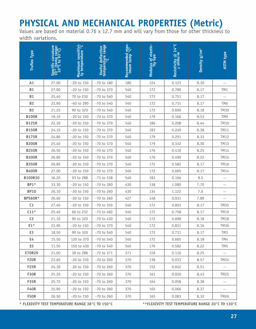
PHYSICAL AND MECHANICAL PROPERTIES (Metric)Values are based on material 0.76 x 12.7 mm and will vary from those for other thickness to width variations.
Trufl
ex T
ype
Spec
ific
curv
atur
e 10
-6 (
tem
p ra
nge:
10
°C t
o 93
°C)
Max
imum
sen
siti
vi-
ty t
empe
ratu
re °
C
Usef
ul d
eflec
tion
te
mpe
ratu
re r
ange
°C
Reco
mm
ende
d m
ax-
imum
tem
p °C
6
Mod
ulus
of
elas
tic-
ity
Gpa
Resi
stiv
ity
@ 2
4°C
µ oh
ms-
m
Dens
ity
g/cm
3
ASTM
typ
e
A1 27.00 -20 to 150 -70 to 180 180 124 0.123 8.30 --
B1 27.00 -20 to 150 -70 to 370 540 172 0.789 8.17 TM1
B1 25.40 70 to 230 -70 to 540 540 172 0.751 8.17 --
B2 23.90 -40 to 290 -70 to 540 540 172 0.731 8.17 TM6
B3 21.25 90 to 320 -70 to 540 540 172 0.690 8.18 TM30
B100R 19.10 -20 to 150 -70 to 370 540 179 0.166 8.53 TM9
B125R 22.30 -20 to 150 -70 to 370 540 186 0.208 8.44 TM10
B150R 24.10 -20 to 150 -70 to 370 540 183 0.249 8.38 TM11
B175R 24.80 -20 to 150 -70 to 370 540 179 0.291 8.33 TM12
B200R 25.40 -20 to 150 -70 to 370 540 179 0.332 8.30 TM13
B250R 26.50 -20 to 150 -70 to 370 540 176 0.416 8.25 TM14
B300R 26.80 -20 to 150 -70 to 370 540 176 0.499 8.22 TM15
B350R 26.80 -20 to 150 -70 to 370 540 172 0.582 8.17 TM16
B400R 27.00 -20 to 150 -70 to 370 540 172 0.665 8.17 TM14
B100R30 16.20 93 to 288 -73 to 538 540 183 0.166 8.5 --
BP1* 33.30 -20 to 150 -70 to 260 430 138 1.080 7.70 --
BP10 26.10 -20 to 150 -70 to 260 430 134 1.122 7.6 --
BP560R* 26.60 -20 to 150 -70 to 260 427 148 0.931 7.89 --
C1 27.40 -20 to 150 -70 to 350 540 172 0.803 8.17 TM35
C11* 25.40 66 to 232 -73 to 482 540 172 0.758 8.17 TM19
C3 21.10 90 to 320 -70 to 430 540 172 0.698 8.18 TM18
E1* 23.90 -20 to 150 -70 to 370 540 172 0.831 8.16 TM36
E3 18.50 90 to 320 -70 to 540 540 172 0.731 8.17 TM3
E4 15.50 120 to 370 -70 to 540 540 172 0.665 8.18 TM4
E5 11.50 150 to 430 -70 to 540 540 176 0.582 8.22 TM5
E70R20 21.00 38 to 288 -72 to 371 371 159 0.116 8.25 --
F20R 23.60 -20 to 150 -70 to 260 370 138 0.033 8.57 TM24
F25R 24.30 -20 to 150 -70 to 260 370 152 0.042 8.51 --
F30R 25.20 -20 to 150 -70 to 260 370 161 0.050 8.43 TM25
F35R 25.70 -20 to 150 -70 to 260 370 164 0.058 8.38 --
F40R 25.90 -20 to 150 -70 to 260 370 165 0.066 8.37 --
F50R 26.50 -20 to 150 -70 to 260 370 165 0.083 8.32 TM26
* FLEXIVITY TEST TEMPERATURE RANGE 38°C TO 150°C **FLEXIVITY TEST TEMPERATURE RANGE 20°C TO 130°C
28
Trufl
ex T
ype
Spec
ific
curv
atur
e 10
-6 (
tem
p ra
nge:
10
°C t
o 93
°C)
Max
imum
sen
siti
vi-
ty t
empe
ratu
re °
C
Usef
ul d
eflec
tion
te
mpe
ratu
re r
ange
°C
Reco
mm
ende
d m
ax-
imum
tem
p °C
6
Mod
ulus
of
elas
tic-
ity
Gpa
Resi
stiv
ity
@ 2
4°C
µ oh
ms-
m
Dens
ity
g/cm
3
ASTM
typ
e
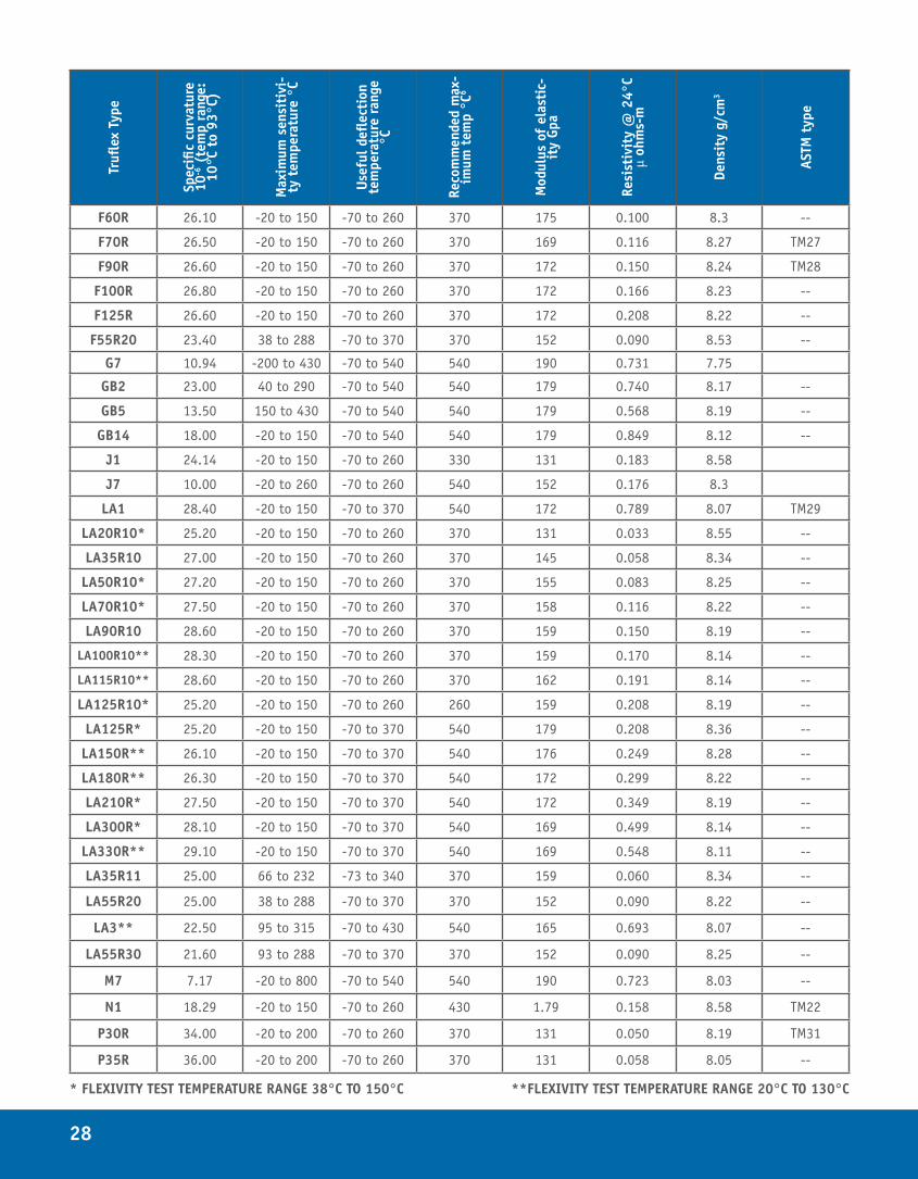
F60R 26.10 -20 to 150 -70 to 260 370 175 0.100 8.3 --
F70R 26.50 -20 to 150 -70 to 260 370 169 0.116 8.27 TM27
F90R 26.60 -20 to 150 -70 to 260 370 172 0.150 8.24 TM28
F100R 26.80 -20 to 150 -70 to 260 370 172 0.166 8.23 --
F125R 26.60 -20 to 150 -70 to 260 370 172 0.208 8.22 --
F55R20 23.40 38 to 288 -70 to 370 370 152 0.090 8.53 --
G7 10.94 -200 to 430 -70 to 540 540 190 0.731 7.75
GB2 23.00 40 to 290 -70 to 540 540 179 0.740 8.17 --
GB5 13.50 150 to 430 -70 to 540 540 179 0.568 8.19 --
GB14 18.00 -20 to 150 -70 to 540 540 179 0.849 8.12 --
J1 24.14 -20 to 150 -70 to 260 330 131 0.183 8.58
J7 10.00 -20 to 260 -70 to 260 540 152 0.176 8.3
LA1 28.40 -20 to 150 -70 to 370 540 172 0.789 8.07 TM29
LA20R10* 25.20 -20 to 150 -70 to 260 370 131 0.033 8.55 --
LA35R10 27.00 -20 to 150 -70 to 260 370 145 0.058 8.34 --
LA50R10* 27.20 -20 to 150 -70 to 260 370 155 0.083 8.25 --
LA70R10* 27.50 -20 to 150 -70 to 260 370 158 0.116 8.22 --
LA90R10 28.60 -20 to 150 -70 to 260 370 159 0.150 8.19 --
LA100R10** 28.30 -20 to 150 -70 to 260 370 159 0.170 8.14 --
LA115R10** 28.60 -20 to 150 -70 to 260 370 162 0.191 8.14 --
LA125R10* 25.20 -20 to 150 -70 to 260 260 159 0.208 8.19 --
LA125R* 25.20 -20 to 150 -70 to 370 540 179 0.208 8.36 --
LA150R** 26.10 -20 to 150 -70 to 370 540 176 0.249 8.28 --
LA180R** 26.30 -20 to 150 -70 to 370 540 172 0.299 8.22 --
LA210R* 27.50 -20 to 150 -70 to 370 540 172 0.349 8.19 --
LA300R* 28.10 -20 to 150 -70 to 370 540 169 0.499 8.14 --
LA330R** 29.10 -20 to 150 -70 to 370 540 169 0.548 8.11 --
LA35R11 25.00 66 to 232 -73 to 340 370 159 0.060 8.34 --
LA55R20 25.00 38 to 288 -70 to 370 370 152 0.090 8.22 --
LA3** 22.50 95 to 315 -70 to 430 540 165 0.693 8.07 --
LA55R30 21.60 93 to 288 -70 to 370 370 152 0.090 8.25 --
M7 7.17 -20 to 800 -70 to 540 540 190 0.723 8.03 --
N1 18.29 -20 to 150 -70 to 260 430 1.79 0.158 8.58 TM22
P30R 34.00 -20 to 200 -70 to 260 370 131 0.050 8.19 TM31
P35R 36.00 -20 to 200 -70 to 260 370 131 0.058 8.05 --
* FLEXIVITY TEST TEMPERATURE RANGE 38°C TO 150°C **FLEXIVITY TEST TEMPERATURE RANGE 20°C TO 130°C
29
Trufl
ex T
ype
Spec
ific
curv
atur
e 10
-6 (
tem
p ra
nge:
10
°C t
o 93
°C)
Max
imum
sen
siti
vi-
ty t
empe
ratu
re °
C
Usef
ul d
eflec
tion
te
mpe
ratu
re r
ange
°C
Reco
mm
ende
d m
ax-
imum
tem
p °C
6
Mod
ulus
of
elas
tic-
ity
Gpa
Resi
stiv
ity
@ 2
4°C
µ oh
ms-
m
Dens
ity
g/cm
3
ASTM
typ
e
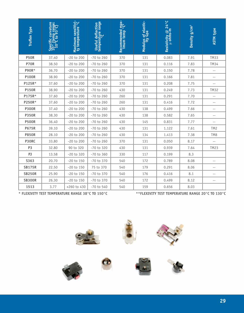
P50R 37.40 -20 to 200 -70 to 260 370 131 0.083 7.91 TM33
P70R 38.50 -20 to 200 -70 to 260 370 131 0.116 7.83 TM34
P90R* 36.70 -20 to 200 -70 to 260 370 131 0.150 7.78 --
P100R 38.90 -20 to 200 -70 to 260 370 131 0.166 7.81 --
P125R* 37.60 -20 to 200 -70 to 260 370 131 0.208 7.75 --
P150R 38.90 -20 to 200 -70 to 260 430 131 0.249 7.73 TM32
P175R* 37.60 -20 to 200 -70 to 260 260 131 0.291 7.70 --
P250R* 37.60 -20 to 200 -70 to 260 260 131 0.416 7.72 --
P300R 37.40 -20 to 200 -70 to 260 430 138 0.499 7.66 --
P350R 38.30 -20 to 200 -70 to 260 430 138 0.582 7.65 --
P500R 36.40 -20 to 200 -70 to 260 430 145 0.831 7.77 --
P675R 39.10 -20 to 200 -70 to 260 430 131 1.122 7.61 TM2
P850R 28.10 -20 to 200 -70 to 260 430 134 1.413 7.38 TM8
P30RC 33.80 -20 to 200 -70 to 260 370 131 0.050 8.17 --
P3 32.80 90 to 320 -70 to 320 430 131 0.939 7.64 TM23
PJ 13.58 -20 to 320 -70 to 360 330 117 0.199 8.3
S363 20.70 -20 to 150 -70 to 370 540 172 0.789 8.08 --
SB175R 22.50 -20 to 150 75 to 370 540 179 0.291 8.06 --
SB250R 25.90 -20 to 150 -70 to 370 540 176 0.416 8.1 --
SB300R 26.30 -20 to 150 -70 to 370 540 172 0.499 8.12 --
1513 3.77 +260 to 430 -70 to 540 540 159 0.656 8.03
* FLEXIVITY TEST TEMPERATURE RANGE 38°C TO 150°C **FLEXIVITY TEST TEMPERATURE RANGE 20°C TO 130°C
30
DESIGN CONSIDERATIONSTHE KEY TO SUCCESS
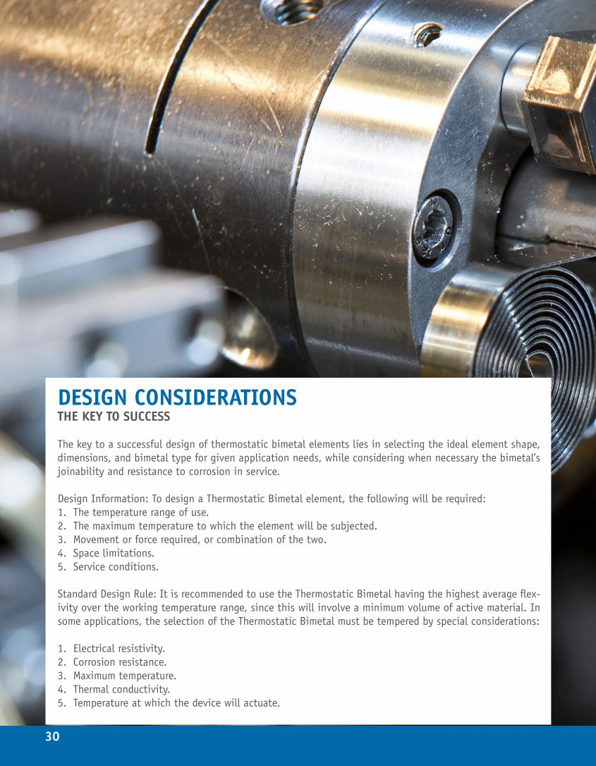
The key to a successful design of thermostatic bimetal elements lies in selecting the ideal element shape, dimensions, and bimetal type for given application needs, while considering when necessary the bimetal’s joinability and resistance to corrosion in service.
Design Information: To design a Thermostatic Bimetal element, the following will be required:1. The temperature range of use.2. The maximum temperature to which the element will be subjected.3. Movement or force required, or combination of the two.4. Space limitations.5. Service conditions.
Standard Design Rule: It is recommended to use the Thermostatic Bimetal having the highest average flex-ivity over the working temperature range, since this will involve a minimum volume of active material. In some applications, the selection of the Thermostatic Bimetal must be tempered by special considerations:
1. Electrical resistivity.2. Corrosion resistance.3. Maximum temperature.4. Thermal conductivity.5. Temperature at which the device will actuate.
31
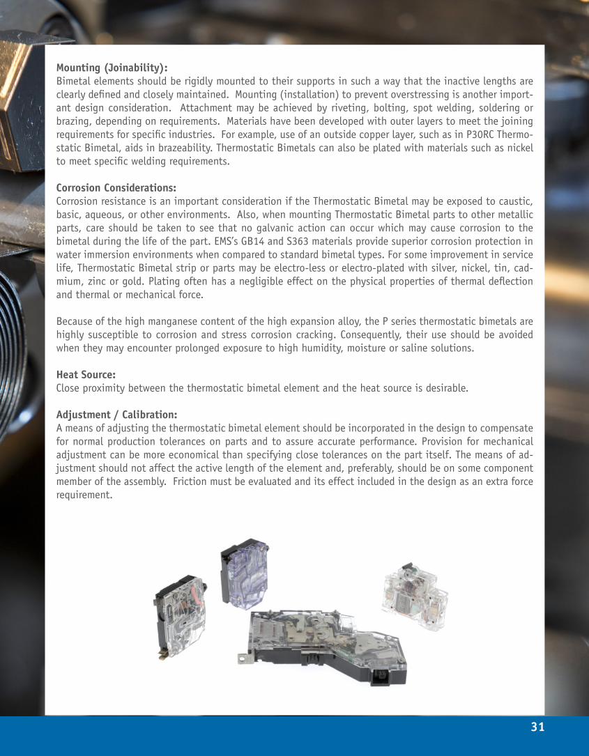
Mounting (Joinability): Bimetal elements should be rigidly mounted to their supports in such a way that the inactive lengths are clearly defined and closely maintained. Mounting (installation) to prevent overstressing is another import-ant design consideration. Attachment may be achieved by riveting, bolting, spot welding, soldering or brazing, depending on requirements. Materials have been developed with outer layers to meet the joining requirements for specific industries. For example, use of an outside copper layer, such as in P30RC Thermo-static Bimetal, aids in brazeability. Thermostatic Bimetals can also be plated with materials such as nickel to meet specific welding requirements.
Corrosion Considerations: Corrosion resistance is an important consideration if the Thermostatic Bimetal may be exposed to caustic, basic, aqueous, or other environments. Also, when mounting Thermostatic Bimetal parts to other metallic parts, care should be taken to see that no galvanic action can occur which may cause corrosion to the bimetal during the life of the part. EMS’s GB14 and S363 materials provide superior corrosion protection in water immersion environments when compared to standard bimetal types. For some improvement in service life, Thermostatic Bimetal strip or parts may be electro-less or electro-plated with silver, nickel, tin, cad-mium, zinc or gold. Plating often has a negligible effect on the physical properties of thermal deflection and thermal or mechanical force.
Because of the high manganese content of the high expansion alloy, the P series thermostatic bimetals are highly susceptible to corrosion and stress corrosion cracking. Consequently, their use should be avoided when they may encounter prolonged exposure to high humidity, moisture or saline solutions.
Heat Source: Close proximity between the thermostatic bimetal element and the heat source is desirable.
Adjustment / Calibration: A means of adjusting the thermostatic bimetal element should be incorporated in the design to compensate for normal production tolerances on parts and to assure accurate performance. Provision for mechanical adjustment can be more economical than specifying close tolerances on the part itself. The means of ad-justment should not affect the active length of the element and, preferably, should be on some component member of the assembly. Friction must be evaluated and its effect included in the design as an extra force requirement.

32
THE EMS ADVANTAGEHistory: EMS has a legacy for excellence and innovation that has provided customers with specialty clad metal solutions since the founding of the General Plate Company in 1916. In 1954 PT (Pressure Temperature) bonding, now the most common method of clad metal bonding, was invented. Over the years EMS has been at the forefront of innovation and development for Thermostatic Bimetal materials.
Facilities: EMS maintains a global presence and provides worldwide customer support by operating three facilities in Attleboro Massachusetts, Hamburg Pennsylvania, and Baoying China. Each facility operates under the same core values that have driven EMS to excellence over the years. Product Variety: EMS currently manufactures 89 Thermostatic Bimetal systems for a wide range of applications. EMS is a world leader in the production of “disc” grade strip materials for snap action devices, as well as in the production of heavy gauge materials for thermal and electrical breakers, thermostatic blades, and thermostatic coils.
Capabilities: EMS has developed an impressive range of capabilities at our worldwide facilities, including:
• Bonding mills with the capability to bond between thicknesses of 0.015” and 0.250”, at widths ranging from 2.0” to 25.5”, and with bond forces up to or exceeding 1000 tons.
• Rolling mills equipped with cluster configurations and automatic gauge control, capable of ensuring excel-lent shape and tight thickness tolerances.
• Continuous strip annealing.• Various strip marking methods, including chemical, embossing, and engraving.• Precision slitting.• Unique flattening modes to meet customer’s specific shape needs.• Precision stamping operations.
Quality: EMS has stringent quality standards and multiple inspections in place to ensure quality products to our custom-ers. EMS tests flexivity, resistivity, and hardness of every lot of Thermostatic Bimetal according to ASTM testing procedures. EMS also employs visual inspections and non-destructive testing techniques to ensure surface qual-ity and bond integrity. EMS certifies chemistry, hardness, flexivity, and resistivity as required by the customer, and maintains full lot traceability from raw stock through finished goods.
Technical Support: EMS is technically adept in engineering the properties of Thermostatic Bimetals. EMS had developed robust and repeatable manufacturing process for making over 100 Thermostatic Bimetal material systems. EMS’s team of technical experts can help assist customers in Thermostatic Bimetal material and property selection. EMS has product specialists and metallurgists that can assist in identifying customer issues that may be related to Ther-mostatic Bimetal. The appendix in this designers guide contains equations and examples for calculating thermal force, mechanical force and thermal deflection for a variety of commonly used Thermostatic Bimetal parts. While the provided equations are helpful in defining a design, it is often advisable to make and test samples before final design is set. EMS has the ability to provide sample material to customers if needed. Contact a product manager if a sample is required.
33
34
APPENDIX: USEFUL EQUATIONS FOR DESIGNERSDESIGN CONFIGURATIONS
Performance: The performance of a Thermostatic Bimetal element is based fundamentally on its ability to deflect and to do work when its temperature is changed.
Thermal deflection: The basic free deflection is utilized without the development of any force. The thermal deflection equations will result in a ratio of thickness to length with an infinite variety of combinations. The final size is determined by factors other than the free deflection specification, such factors being rigidity, resistance to vibration, space limitations and practicality for production.
Thermal force: The basic free deflection is completely prevented, and only force is developed. The thermal force equations will result in a ratio of width, thickness and length with an infinite variety of combinations. Aside from the thermal force specifications, the final size will be determined by the same factors as for free deflection, plus the factor of allowable stress.
Thermal deflection and force: Part of the potential free deflection is prevented and transformed into force which the element develops in ad-dition to a deflection. This is the most common application of thermostatic bimetal. By utilizing one half the available temperature change for developing thermal deflection and the other half for developing thermal force, a minimum volume of material is involved. However, due to dimensional, fabricating, assembly and allowable stress considerations, it may be advisable to deviate from this 50-50 optimum division. In so doing, there are an infinite number of variations which can be calculated; however, there are a few interesting limitations. If one-third of the total available temperature change is used for developing force, the formulas will arrive at the short-est element for a given width for these types: cantilever, simple beam, U-shape spiral or helix coil. If two-thirds of the total available temperature change is used for developing force, the thinnest element for a given width is obtained for cantilevers, simple beams and U-shapes. By using most of the available temperature change to produce force in spiral and helix coils, the strip can be made as thin as is practical; however, this necessitates increasing the length of the strip proportionally.
Change in slope: Sometimes it is important to know the change in slope of the end or some other point of a thermostatic bimetal element. For an element free to move, this change is given by the thermal deflection formula for spiral and helix coils but it applies to any shape element.
Minimum volume of material: Using the thermostatic bimetal with the highest flexivity in the working temperature range permits the use of a minimum volume of material for a given combination of deflection and force.
KEY TO SYMBOLS USED IN FORMULAS
• Thickness (t), Width (w), Length (L), Deflection (B), Outer Disc Diameter (D), Inner Disc Diameter (d), and Radius (r) in inches
• Angular Deflection (A) in degrees
35
• Modulus of Elasticity (E) in Psi• Flexivity (F) in (in/in)/(°F)• Force (P) in ounces• Temperature Change (T2-T1) in °F
GENERAL LAWS GOVERNING THERMOSTATIC BIMETALS
DEFLECTION on temperature change varies:
For cantilever, Simple Beam, and U shape For Spiral and HelixDirectly as temperature change Directly as temperature changeDirectly as length squared Directly as lengthInversely as thickness Inversely as thickness
FORCE exerted on temperature change varies:
For cantilever, Simple Beam, and U shape For Spiral and HelixDirectly as temperature change Directly as temperature changeDirectly as width Directly as widthInversely as thickness squared Inversely as thickness squaredInversely as length Inversely as radius
*Note: Only two properties of thermostatic bimetal, flexivity (F) and modulus of elasticity (E), are needed to solve any or all the formulas in this guide.
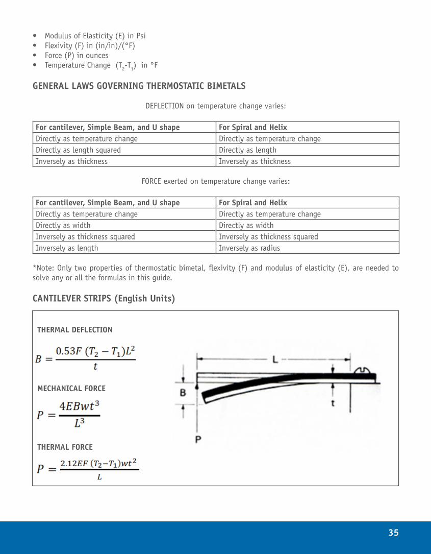
CANTILEVER STRIPS (English Units)
THERMAL DEFLECTION
MECHANICAL FORCE
THERMAL FORCE
36
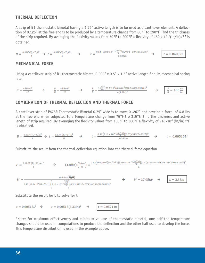
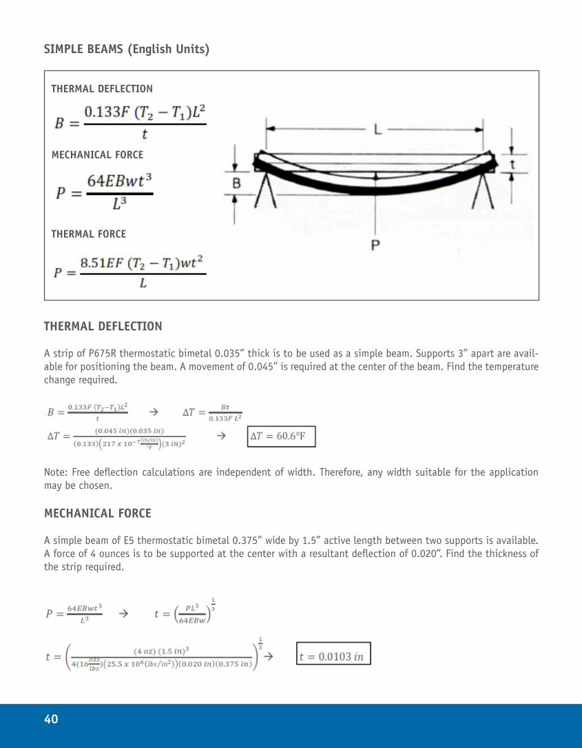
THERMAL DEFLECTION
A strip of B1 thermostatic bimetal having a 1.75" active length is to be used as a cantilever element. A deflec-tion of 0.125" at the free end is to be produced by a temperature change from 80°F to 290°F. Find the thickness of the strip required. By averaging the flexivity values from 50°F to 200°F a flexivity of 150 x 10-7(in/in)/°F is obtained.
MECHANICAL FORCE
Using a cantilever strip of B1 thermostatic bimetal 0.030" x 0.5" x 1.5" active length find its mechanical spring rate.
COMBINATION OF THERMAL DEFLECTION AND THERMAL FORCE
A cantilever strip of P675R Thermostatic Bimetal 0.75" wide is to move 0 .267" and develop a force of 4.8 lbs at the free end when subjected to a temperature change from 75°F t o 315°F. Find the thickness and active length of strip required. By averaging the flexivity values from 100°F to 300°F a flexivity of 216×10-7 (in/in)/°F is obtained.
Substitute the result from the thermal deflection equation into the thermal force equation
Substitute the result for L to solve for t
*Note: For maximum effectiveness and minimum volume of thermostatic bimetal, one half the temperature changes should be used in computations to produce the deflection and the other half used to develop the force. This temperature distribution is used in the example above.
37
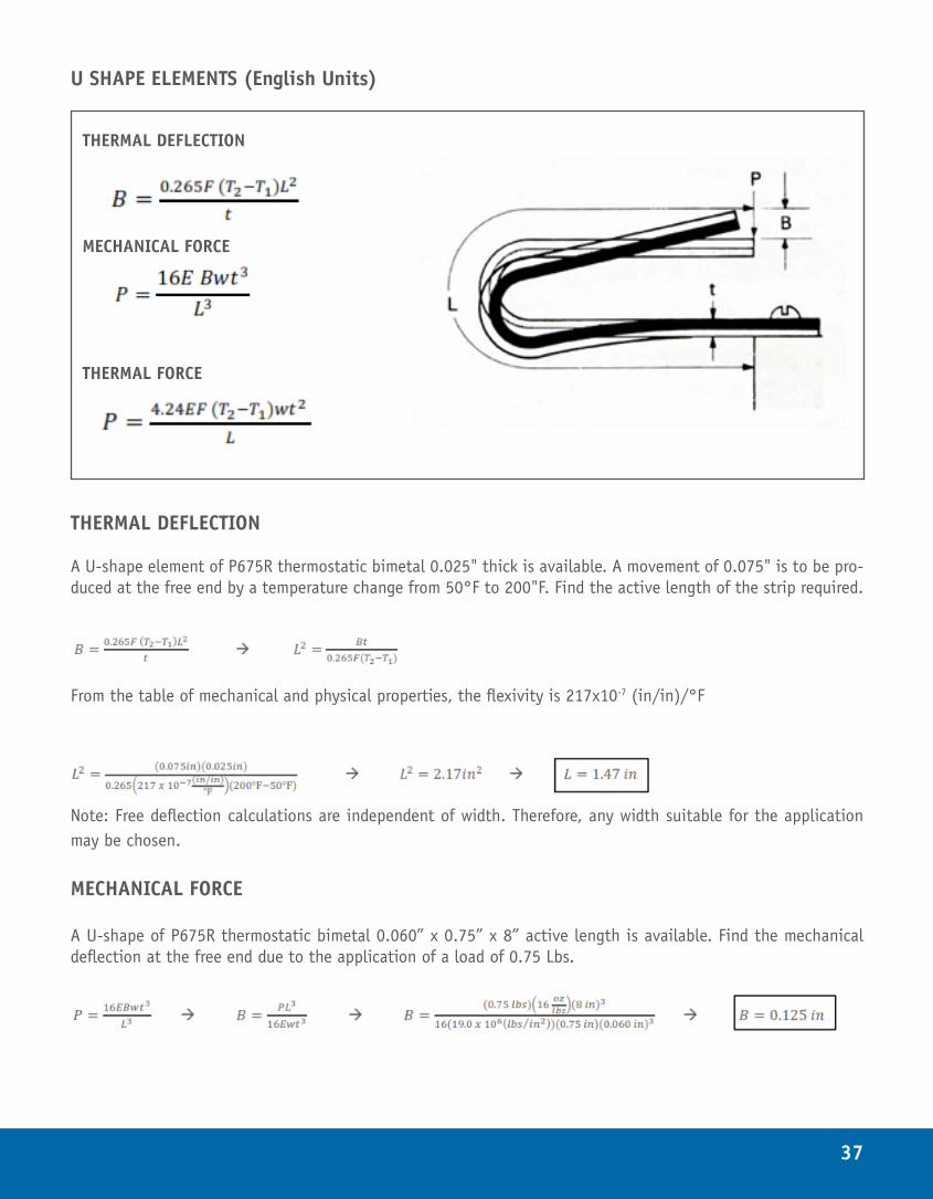
U SHAPE ELEMENTS (English Units)
THERMAL DEFLECTION
A U-shape element of P675R thermostatic bimetal 0.025" thick is available. A movement of 0.075" is to be pro-duced at the free end by a temperature change from 50°F to 200"F. Find the active length of the strip required.
From the table of mechanical and physical properties, the flexivity is 217x10-7 (in/in)/°F
Note: Free deflection calculations are independent of width. Therefore, any width suitable for the application may be chosen.
MECHANICAL FORCE
A U-shape of P675R thermostatic bimetal 0.060” x 0.75” x 8” active length is available. Find the mechanical deflection at the free end due to the application of a load of 0.75 Lbs.
THERMAL DEFLECTION
MECHANICAL FORCE
THERMAL FORCE
38
COMBINATION OF THERMAL DEFLECTION AND THERMAL FORCE
A space of about 1" length is available to accommodate a U- shape element with an active length of 1.6". A movement of 0.067" and a force of 5.5 ounces at the free end is to be produced by a temperature change from 50°F to 250°F. The material must withstand a temperature of 700°F. Find the type of material, its thickness and width.
(1) First choose a material. Materials should be chosen such that they can withstand the maximum service tem-perature.
Note: P675R being the most active in this temperature range would ordinarily be selected. The temperature limitation dictates the use of B1 with a flexivity of 149 x 10-7(in/in)/°F, from 50 to 250°F.
Substitute the thickness into the Thermal Force Equation
*Note: for maximum effectiveness and minimum volume of thermostatic bimetal, one half of the temperature change should be used in computations to produce the deflection and the other half used to develop the force. This temperature distribution is used in the example above.
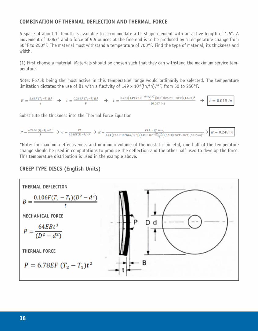
CREEP TYPE DISCS (English Units)
THERMAL DEFLECTION
MECHANICAL FORCE
THERMAL FORCE
39
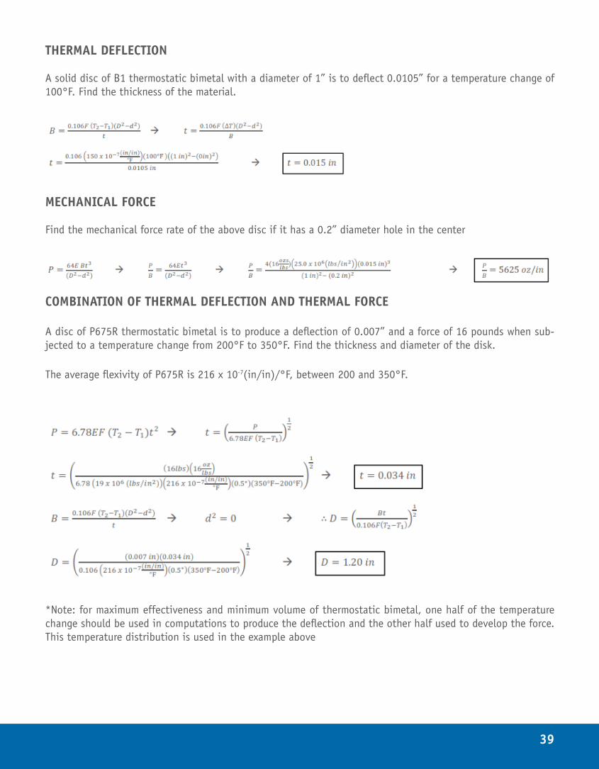
THERMAL DEFLECTION
A solid disc of B1 thermostatic bimetal with a diameter of 1” is to deflect 0.0105” for a temperature change of 100°F. Find the thickness of the material.
MECHANICAL FORCE
Find the mechanical force rate of the above disc if it has a 0.2” diameter hole in the center
COMBINATION OF THERMAL DEFLECTION AND THERMAL FORCE
A disc of P675R thermostatic bimetal is to produce a deflection of 0.007” and a force of 16 pounds when sub-jected to a temperature change from 200°F to 350°F. Find the thickness and diameter of the disk.
The average flexivity of P675R is 216 x 10-7(in/in)/°F, between 200 and 350°F.
*Note: for maximum effectiveness and minimum volume of thermostatic bimetal, one half of the temperature change should be used in computations to produce the deflection and the other half used to develop the force. This temperature distribution is used in the example above
40
SIMPLE BEAMS (English Units)
THERMAL DEFLECTION
A strip of P675R thermostatic bimetal 0.035” thick is to be used as a simple beam. Supports 3” apart are avail-able for positioning the beam. A movement of 0.045” is required at the center of the beam. Find the temperature change required.
Note: Free deflection calculations are independent of width. Therefore, any width suitable for the application may be chosen.
MECHANICAL FORCE
A simple beam of E5 thermostatic bimetal 0.375” wide by 1.5” active length between two supports is available. A force of 4 ounces is to be supported at the center with a resultant deflection of 0.020”. Find the thickness of the strip required.
THERMAL DEFLECTION
MECHANICAL FORCE
THERMAL FORCE
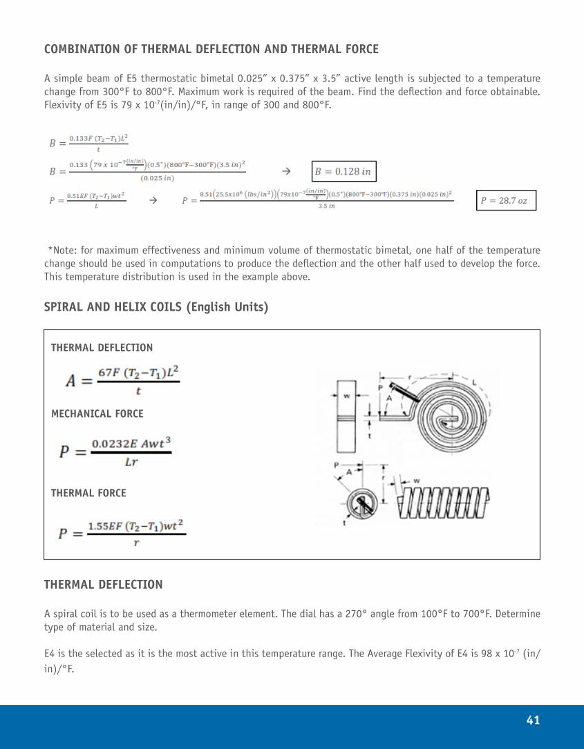
41
COMBINATION OF THERMAL DEFLECTION AND THERMAL FORCE
A simple beam of E5 thermostatic bimetal 0.025” x 0.375” x 3.5” active length is subjected to a temperature change from 300°F to 800°F. Maximum work is required of the beam. Find the deflection and force obtainable. Flexivity of E5 is 79 x 10-7(in/in)/°F, in range of 300 and 800°F.
*Note: for maximum effectiveness and minimum volume of thermostatic bimetal, one half of the temperature change should be used in computations to produce the deflection and the other half used to develop the force. This temperature distribution is used in the example above.
SPIRAL AND HELIX COILS (English Units)
THERMAL DEFLECTION
A spiral coil is to be used as a thermometer element. The dial has a 270° angle from 100°F to 700°F. Determine type of material and size.
E4 is the selected as it is the most active in this temperature range. The Average Flexivity of E4 is 98 x 10-7 (in/in)/°F.
THERMAL DEFLECTION
MECHANICAL FORCE
THERMAL FORCE
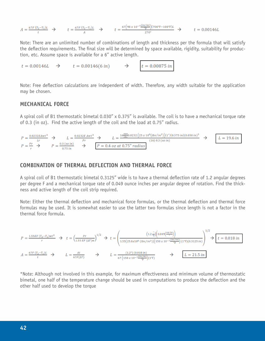
42
Note: There are an unlimited number of combinations of length and thickness per the formula that will satisfy the deflection requirements. The final size will be determined by space available, rigidity, suitability for produc-tion, etc. Assume space is available for a 6” active length.
Note: Free deflection calculations are independent of width. Therefore, any width suitable for the application may be chosen.
MECHANICAL FORCE
A spiral coil of B1 thermostatic bimetal 0.030” x 0.375” is available. The coil is to have a mechanical torque rate of 0.3 (in oz). Find the active length of the coil and the load at 0.75” radius.
COMBINATION OF THERMAL DEFLECTION AND THERMAL FORCE
A spiral coil of B1 thermostatic bimetal 0.3125” wide is to have a thermal deflection rate of 1.2 angular degrees per degree F and a mechanical torque rate of 0.049 ounce inches per angular degree of rotation. Find the thick-ness and active length of the coil strip required.
Note: Either the thermal deflection and mechanical force formulas, or the thermal deflection and thermal force formulas may be used. It is somewhat easier to use the latter two formulas since length is not a factor in the thermal force formula.
*Note: Although not involved in this example, for maximum effectiveness and minimum volume of thermostatic bimetal, one half of the temperature change should be used in computations to produce the deflection and the other half used to develop the torque
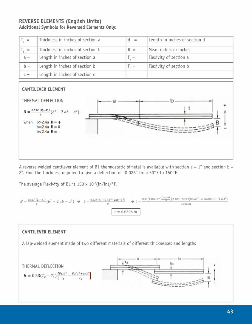
43
REVERSE ELEMENTS (English Units)Additional Symbols for Reversed Elements Only:
Ta = Thickness in inches of section a d = Length in inches of section d
Tb = Thickness in inches of section b R = Mean radius in inches
a = Length in inches of section a Fa = Flexivity of section a
b = Length in inches of section b Fb = Flexivity of section b
c = Length in inches of section c
A reverse welded cantilever element of B1 thermostatic bimetal is available with section a = 1” and section b = 2”. Find the thickness required to give a deflection of -0.026” from 50°F to 150°F.
The average Flexivity of B1 is 150 x 10-7(in/in)/°F.
CANTILEVER ELEMENT THERMAL DEFLECTION
CANTILEVER ELEMENT
A lap-welded element made of two different materials of different thicknesses and lengths
THERMAL DEFLECTION
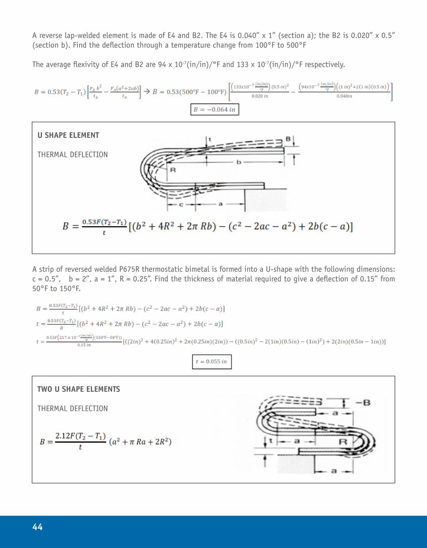
44
A reverse lap-welded element is made of E4 and B2. The E4 is 0.040” x 1” (section a); the B2 is 0.020” x 0.5” (section b). Find the deflection through a temperature change from 100°F to 500°F
The average flexivity of E4 and B2 are 94 x 10-7(in/in)/°F and 133 x 10-7(in/in)/°F respectively.
A strip of reversed welded P675R thermostatic bimetal is formed into a U-shape with the following dimensions: c = 0.5”, b = 2”, a = 1”, R = 0.25”. Find the thickness of material required to give a deflection of 0.15” from 50°F to 150°F.
U SHAPE ELEMENT THERMAL DEFLECTION
TWO U SHAPE ELEMENTS THERMAL DEFLECTION
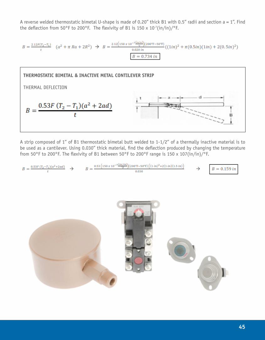
45
A reverse welded thermostatic bimetal U-shape is made of 0.20” thick B1 with 0.5” radii and section a = 1”. Find the deflection from 50°F to 200°F. The flexivity of B1 is 150 x 10-7(in/in)/°F.
A strip composed of 1” of B1 thermostatic bimetal butt welded to 1-1/2” of a thermally inactive material is to be used as a cantilever. Using 0.030” thick material, find the deflection produced by changing the temperature from 50°F to 200°F. The flexivity of B1 between 50°F to 200°F range is 150 x 107(in/in)/°F.
THERMOSTATIC BIMETAL & INACTIVE METAL CONTILEVER STRIP THERMAL DEFLECTION
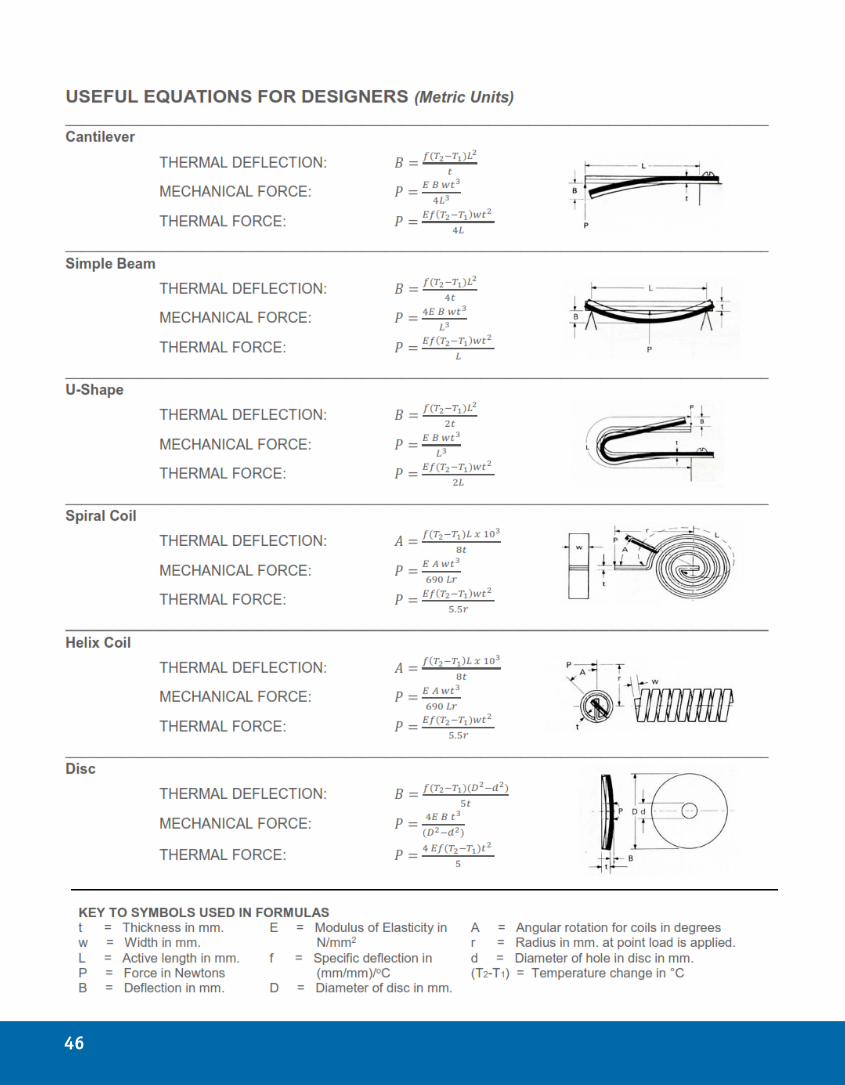
46
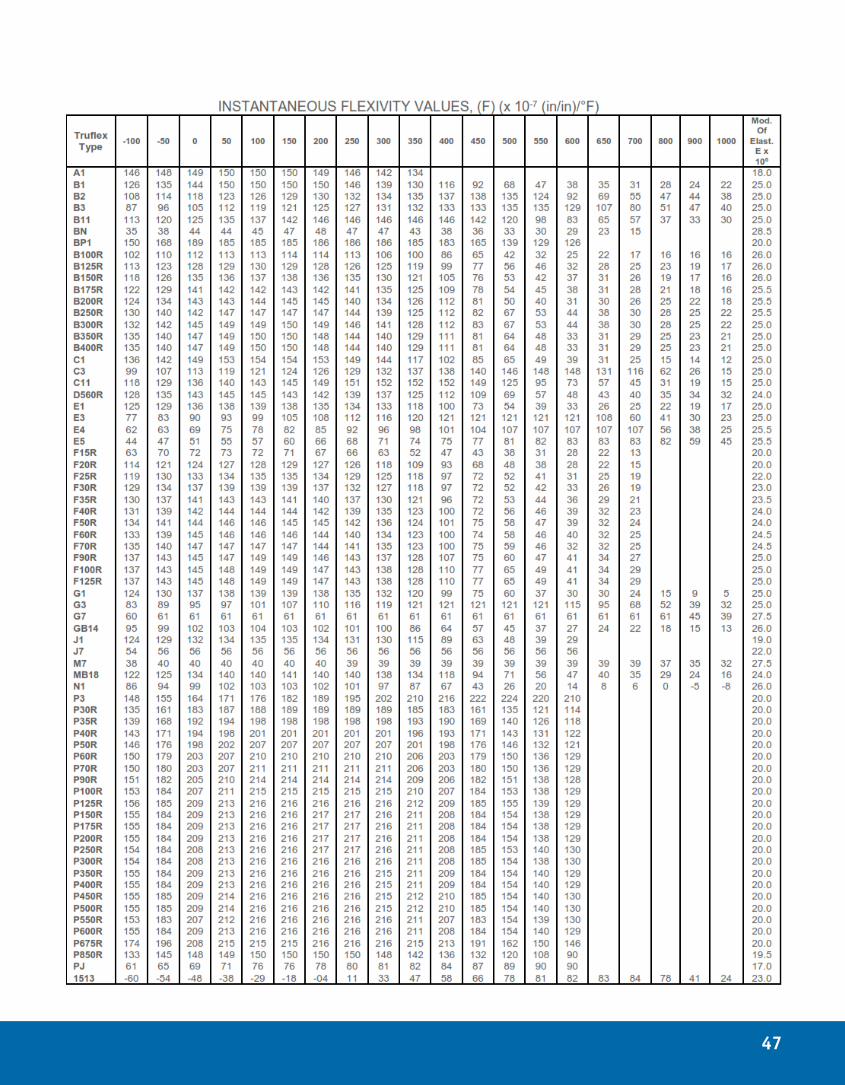
47
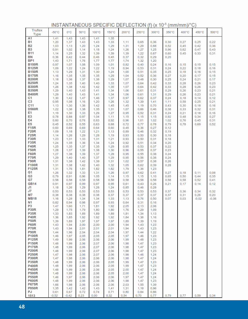
48
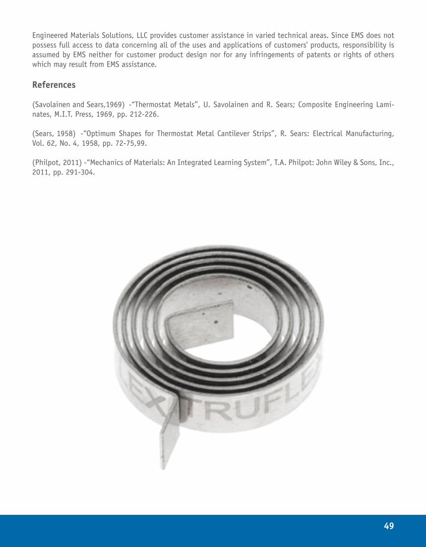
49
Engineered Materials Solutions, LLC provides customer assistance in varied technical areas. Since EMS does not possess full access to data concerning all of the uses and applications of customers' products, responsibility is assumed by EMS neither for customer product design nor for any infringements of patents or rights of others which may result from EMS assistance.
References
(Savolainen and Sears,1969) -“Thermostat Metals”, U. Savolainen and R. Sears; Composite Engineering Lami-nates, M.I.T. Press, 1969, pp. 212-226.
(Sears, 1958) -“Optimum Shapes for Thermostat Metal Cantilever Strips”, R. Sears: Electrical Manufacturing, Vol. 62, No. 4, 1958, pp. 72-75,99.
(Philpot, 2011) -“Mechanics of Materials: An Integrated Learning System”, T.A. Philpot: John Wiley & Sons, Inc., 2011, pp. 291-304.

www.emsclad.com
Engineered Materials Solutions EMSA39 Perry AvenueAttleboro, MA 02703Phone: +1 508 342 2100Fax: +1 508 342 2125E-mail: [email protected]
Engineered Materials Solutions EMSH600 Valley RoadHamburg, PA 19526Phone: +1 610 562 3841Fax: +610 562 5800 E-mail: [email protected]
Engineered Materials Solutions EMSCItalian Industrial Park Baoying, Jiangsu, 225800 PR ChinaPhone: +86 514 8891 6888Fax: +86 514 8891 6889E-mail: [email protected]