Embed Size (px)
Citation preview
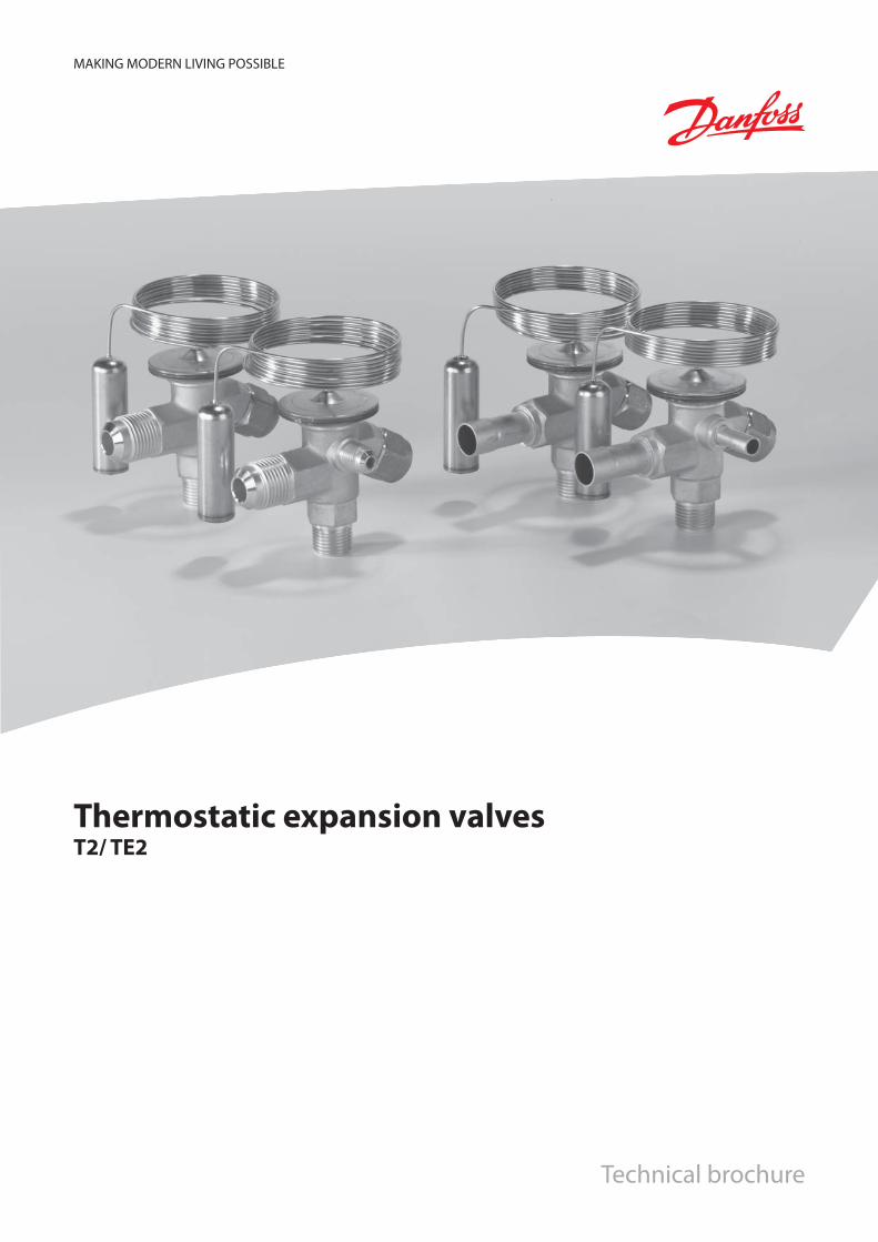
MAKING MODERN LIVING POSSIBLE
Thermostatic expansion valvesT2/ TE2
Technical brochure
Technical leafl et Thermostatic expansion valves, type T 2 and TE 2
2 DKRCC.PD.AA0.A3.02 / 520H2881 © Danfoss A/S (RA-MC / mr), 03 - 2009
Contents Page
Introduction. . . . . . . . . . . . . . . . . . . . . . . . . . . . . . . . . . . . . . . . . . . . . . . . . . . . . . . . . . . . . . . . . . . . . . . . . . . . . . . . . . . . . . . .3
Features . . . . . . . . . . . . . . . . . . . . . . . . . . . . . . . . . . . . . . . . . . . . . . . . . . . . . . . . . . . . . . . . . . . . . . . . . . . . . . . . . . . . . . . . . . . .3
Technical data . . . . . . . . . . . . . . . . . . . . . . . . . . . . . . . . . . . . . . . . . . . . . . . . . . . . . . . . . . . . . . . . . . . . . . . . . . . . . . . . . . . . . .3
Superheat . . . . . . . . . . . . . . . . . . . . . . . . . . . . . . . . . . . . . . . . . . . . . . . . . . . . . . . . . . . . . . . . . . . . . . . . . . . . . . . . . .3
Ordering: . . . . . . . . . . . . . . . . . . . . . . . . . . . . . . . . . . . . . . . . . . . . . . . . . . . . . . . . . . . . . . . . . . . . . . . . . . . . . . . . . . . . . . . . . . . .
Components with fl are × fl are connection . . . . . . . . . . . . . . . . . . . . . . . . . . . . . . . . . . . . . . . . . . . . . . . . . . . . . . .4
Flare connections . . . . . . . . . . . . . . . . . . . . . . . . . . . . . . . . . . . . . . . . . . . . . . . . . . . . . . . . . . . . . . . . . . . . . . . . . . .4
Orifi ce assembly with fi lter . . . . . . . . . . . . . . . . . . . . . . . . . . . . . . . . . . . . . . . . . . . . . . . . . . . . . . . . . . . . . . . . . .4
Components with fl are × solder connection . . . . . . . . . . . . . . . . . . . . . . . . . . . . . . . . . . . . . . . . . . . . . . . . . . . . .4
Solder adaptor . . . . . . . . . . . . . . . . . . . . . . . . . . . . . . . . . . . . . . . . . . . . . . . . . . . . . . . . . . . . . . . . . . . . . . . . . . . . . .5
Orifi ce assembly with fi lter for solder adapter . . . . . . . . . . . . . . . . . . . . . . . . . . . . . . . . . . . . . . . . . . . . . . . .5
Capacity:
R22. . . . . . . . . . . . . . . . . . . . . . . . . . . . . . . . . . . . . . . . . . . . . . . . . . . . . . . . . . . . . . . . . . . . . . . . . . . . . . . . . . . . . . . . . . . . .6
R407C . . . . . . . . . . . . . . . . . . . . . . . . . . . . . . . . . . . . . . . . . . . . . . . . . . . . . . . . . . . . . . . . . . . . . . . . . . . . . . . . . . . . . . . . . .7
R134a . . . . . . . . . . . . . . . . . . . . . . . . . . . . . . . . . . . . . . . . . . . . . . . . . . . . . . . . . . . . . . . . . . . . . . . . . . . . . . . . . . . . . . . . . .8
R404A / R507 . . . . . . . . . . . . . . . . . . . . . . . . . . . . . . . . . . . . . . . . . . . . . . . . . . . . . . . . . . . . . . . . . . . . . . . . . . . . . . . . . . .9
Design - Function. . . . . . . . . . . . . . . . . . . . . . . . . . . . . . . . . . . . . . . . . . . . . . . . . . . . . . . . . . . . . . . . . . . . . . . . . . . . . . . . . 10
Identifi cation . . . . . . . . . . . . . . . . . . . . . . . . . . . . . . . . . . . . . . . . . . . . . . . . . . . . . . . . . . . . . . . . . . . . . . . . . . . . . . . . . . . . . 11
Dimensions and weights . . . . . . . . . . . . . . . . . . . . . . . . . . . . . . . . . . . . . . . . . . . . . . . . . . . . . . . . . . . . . . . . . . . . . . . . . . 11
R22 100 psig/6.9 bar 60 psig/4.0 bar 35 psig/3.5 bar 20 psig/1.5 bar
R407C 95 psig/6.6 bar
R134a 55 psig/5.0 bar 30 psig/3.1 bar 15 psig/2.1 bar
R404A/R507 120 psig/9.3 bar 75 psig/6.2 bar 50 psig/4.4 bar 30 psig/3.1 bar
Technical leafl et Thermostatic expansion valves, type T 2 and TE 2
© Danfoss A/S (RA-MC / mr), 03 - 2009 DKRCC.PD.AA0.A3.02 / 520H2881 3
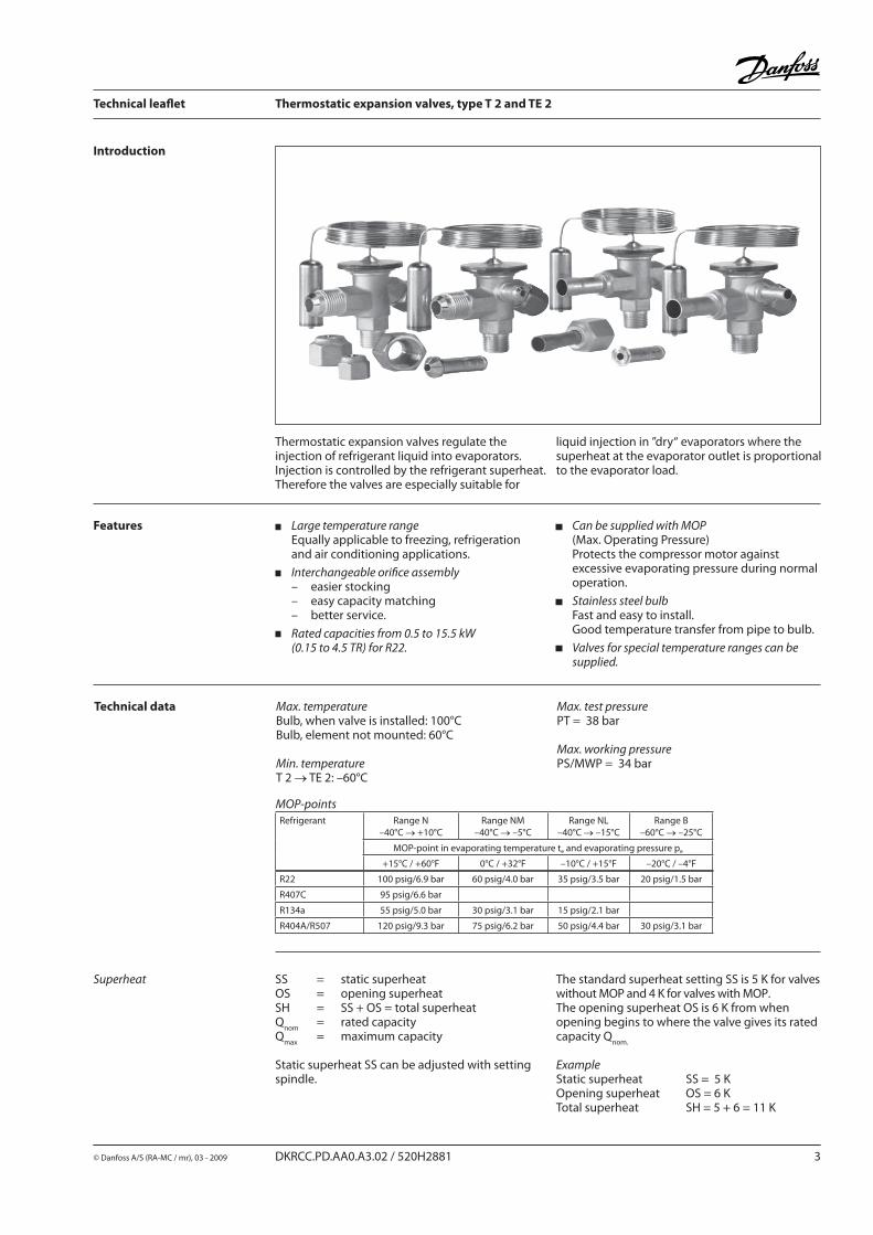
liquid injection in ”dry“ evaporators where the superheat at the evaporator outlet is proportional to the evaporator load.
Large temperature rangeEqually applicable to freezing, refrigeration and air conditioning applications.
Interchangeable orifi ce assembly– easier stocking– easy capacity matching– better service.
Rated capacities from 0.5 to 15.5 kW(0.15 to 4.5 TR) for R22.
Can be supplied with MOP(Max. Operating Pressure)Protects the compressor motor against excessive evaporating pressure during normal operation.
Stainless steel bulbFast and easy to install.Good temperature transfer from pipe to bulb.
Valves for special temperature ranges can be supplied.
Features
Thermostatic expansion valves regulate the injection of refrigerant liquid into evaporators.Injection is controlled by the refrigerant superheat. Therefore the valves are especially suitable for
Introduction
Technical data Max. temperatureBulb, when valve is installed: 100°CBulb, element not mounted: 60°C
Min. temperatureT 2 → TE 2: –60°C
Max. test pressurePT = 38 bar
Max. working pressurePS/MWP = 34 bar
SS = static superheatOS = opening superheatSH = SS + OS = total superheatQ
nom = rated capacity
Qmax
= maximum capacity
Static superheat SS can be adjusted with setting spindle.
Superheat The standard superheat setting SS is 5 K for valves without MOP and 4 K for valves with MOP.The opening superheat OS is 6 K from when opening begins to where the valve gives its rated capacity Q
nom.
ExampleStatic superheat SS = 5 KOpening superheat OS = 6 KTotal superheat SH = 5 + 6 = 11 K
MOP-pointsRefrigerant Range N
–40°C → +10°CRange NM
–40°C → –5°CRange NL
–40°C → –15°CRange B
–60°C → –25°C
MOP-point in evaporating temperature te and evaporating pressure pe
+15°C / +60°F 0°C / +32°F –10°C / +15°F –20°C / –4°F
R22 TX 2 Int. 1.5 3/8 × 1/2 10 × 12 068Z3206 068Z3208 068Z3224 068Z3226 068Z3207 068Z3228
TEX 2 Ext. 1.5 3/8 × 1/2 10 × 12 068Z3209 068Z3211 068Z3225 068Z3227 068Z3210 068Z3229
R407C TZ 2 Int. 1.5 3/8 × 1/2 10 × 12 068Z3496 068Z3516
TEZ 2 Ext. 1.5 3/8 × 1/2 10 × 12 068Z3501 068Z3517
R134a TN 2 Int. 1.5 3/8 × 1/2 10 × 12 068Z3346 068Z3347 068Z3393 068Z3369
TEN 2 Ext. 1.5 3/8 × 1/2 10 × 12 068Z3348 068Z3349 068Z3392 068Z3370
R404A/R507
TS 2 Int. 1.5 3/8 × 1/2 10 × 12 068Z3400 068Z3402 068Z3406 068Z3408 068Z3401 068Z3410
TES 2 Ext. 1.5 3/8 × 1/2 10 × 12 068Z3403 068Z3405 068Z3407 068Z3409 068Z3404 068Z3411
1/4 6 011L1101
3/8 10 011L1135
1/2 12 011L1103
1/4 6 011L1107
0X 0.15 0.16 0.11 0.11 0.50 0.50 0.40 0.38 068-2002
00 0.30 0.30 0.25 0.21 1.0 1.1 0.90 0.70 068-2003
01 0.70 0.80 0.50 0.45 2.5 2.7 1.8 1.6 068-2010
02 1.0 1.1 0.80 0.60 3.5 3.8 2.6 2.1 068-2015
03 1.5 1.6 1.3 1.2 5.2 5.6 4.6 4.2 068-2006
04 2.3 2.5 1.9 1.7 8.0 8.6 6.7 6.0 068-2007
05 3.0 3.2 2.5 2.2 10.5 11.3 8.6 7.7 068-2008
06 4.5 4.9 3.0 2.6 15.5 16.7 10.5 9.1 068-2009
0X 0.15 0.11 0.50 0.38 068-2002
00 0.20 0.21 0.70 0.70 068-2003
01 0.30 0.45 1.0 1.6 068-2010
02 0.60 0.60 2.1 2.1 068-2015
03 0.80 1.0 2.8 3.5 068-2006
04 1.2 1.4 4.2 4.9 068-2007
05 1.5 1.7 5.2 6.0 068-2008
06 2.0 1.9 7.0 6.6 068-2009
Technical leafl et Thermostatic expansion valves, type T 2 and TE 2
4 DKRCC.PD.AA0.A3.02 / 520H2881 © Danfoss A/S (RA-MC / mr), 03 - 2009
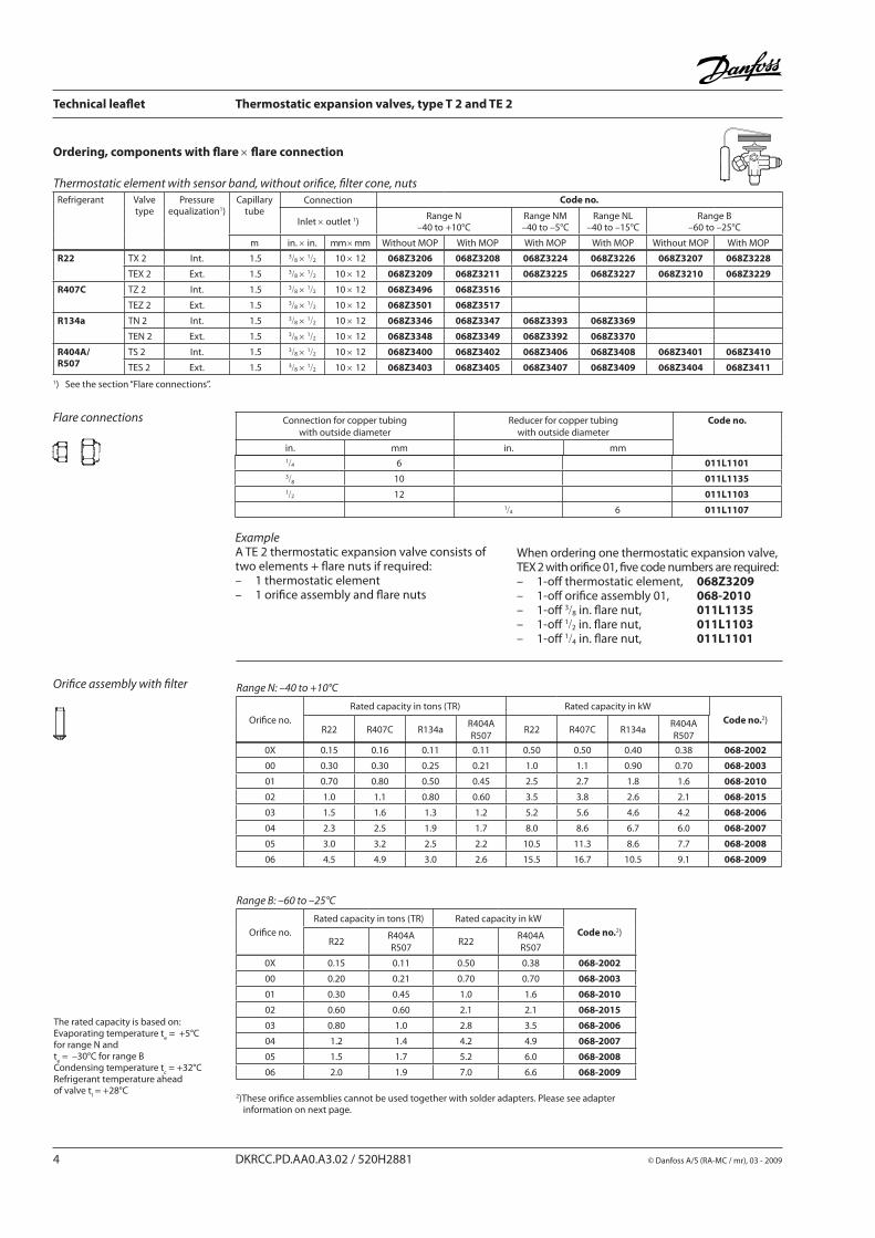
Ordering, components with fl are × fl are connection
Flare connections
ExampleA TE 2 thermostatic expansion valve consists of two elements + fl are nuts if required:– 1 thermostatic element– 1 orifi ce assembly and fl are nuts
When ordering one thermostatic expansion valve, TEX 2 with orifi ce 01, fi ve code numbers are required:– 1-off thermostatic element, 068Z3209– 1-off orifi ce assembly 01, 068-2010– 1-off 3/8 in. fl are nut, 011L1135– 1-off 1/2 in. fl are nut, 011L1103– 1-off 1/4 in. fl are nut, 011L1101
Thermostatic element with sensor band, without orifi ce, fi lter cone, nutsRefrigerant Valve
typePressure
equalization1)Capillary
tubeConnection Code no.
Inlet × outlet 1)Range N
–40 to +10°CRange NM–40 to –5°C
Range NL–40 to –15°C
Range B–60 to –25°C
m in. × in. mm × mm Without MOP With MOP With MOP With MOP Without MOP With MOP
Connection for copper tubingwith outside diameter
Reducer for copper tubingwith outside diameter
Code no.
in. mm in. mm
Orifi ce assembly with fi lter
The rated capacity is based on:Evaporating temperature t
e = +5°C
for range N and t
e = –30°C for range B
Condensing temperature tc = +32°C
Refrigerant temperature ahead of valve t
l = +28°C
Range N: –40 to +10°C
Orifi ce no.
Rated capacity in tons (TR) Rated capacity in kW
Code no.2)R22 R407C R134a
R404AR507
R22 R407C R134aR404AR507
Range B: –60 to –25°C
Orifi ce no.
Rated capacity in tons (TR) Rated capacity in kW
Code no.2)R22
R404AR507
R22R404AR507
2)These orifi ce assemblies cannot be used together with solder adapters. Please see adapter information on next page.
1) See the section “Flare connections”.
R22
TX 2 Int. 1.5 3/81/2 068Z3281 068Z3287 068Z3357 068Z3319
TX 2 Int. 1.5 10 12 068Z3302 068Z3308 068Z3366 068Z3361 068Z3276
TEX 2 Ext. 1.5 3/81/2 068Z3284 068Z3290 068Z3359 068Z3320
TEX 2 Ext. 1.5 10 12 068Z3305 068Z3311 068Z3367 068Z3363 068Z3277
R407C
TZ 2 Int. 1.5 3/81/2 068Z3329
TZ 2 Int. 1.5 10 12 068Z3502 068Z3514
TEZ 2 Ext. 1.5 3/81/2 068Z3446 068Z3447
TEZ 2 Ext. 1.5 10 12 068Z3503 068Z3515
R134a
TN 2 Int. 1.5 3/81/2 068Z3383 068Z3387
TN 2 Int. 1.5 10 12 068Z3384 068Z3388
TEN 2 Ext. 1.5 3/81/2 068Z3385 068Z3389
TEN 2 Ext. 1.5 10 12 068Z3386 068Z3390
R 404A/R507
TS 2 Int. 1.5 3/81/2 068Z3414 068Z3416 068Z3429 068Z3418 068Z3420
TS 2 Int. 1.5 10 12 068Z3435 068Z3423 068Z3436 068Z3425 068Z3427
TES 2 Ext. 1.5 3/81/2 068Z3415 068Z3417 068Z3430 068Z3419 068Z3421
TES 2 Ext. 1.5 10 12 068Z3422 068Z3424 068Z3437 068Z3426 068Z3428
1/4 in. 068-2062
6 mm 068-2063
3/8 in. 068-2060
10 mm 068-2061
0X 068-2089
00 068-2090
01 068-2091
02 068-2092
03 068-2093
04 068-2094
05 068-2095
06 068-2096
Technical leafl et Thermostatic expansion valves, type T 2 and TE 2
© Danfoss A/S (RA-MC / mr), 03 - 2009 DKRCC.PD.AA0.A3.02 / 520H2881 5
Flare connections See previous page.
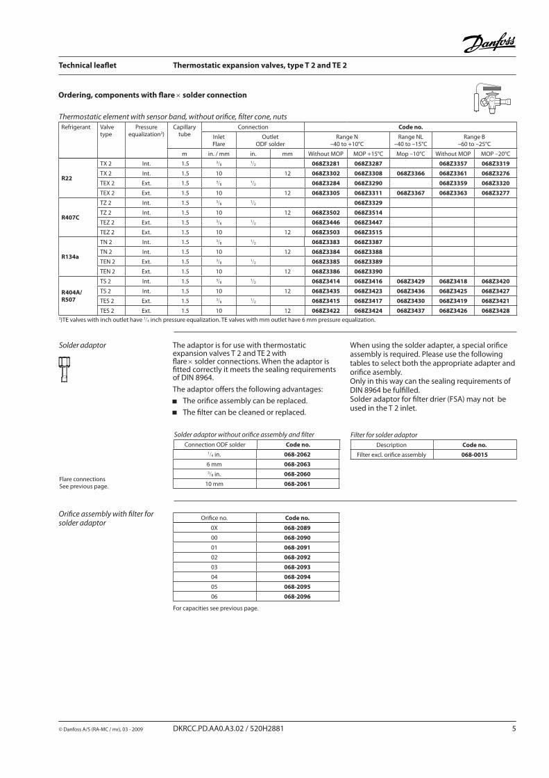
The adaptor is for use with thermostatic expansion valves T 2 and TE 2 with fl are × sol der connections. When the adaptor is fi tted correctly it meets the sealing requirements of DIN 8964.
The adaptor off ers the following advantages:
The orifi ce assembly can be replaced.
The fi lter can be cleaned or replaced.
When using the sol der adapter, a special orifi ce assembly is required. Please use the following tables to select both the appropriate adapter and orifi ce asembly.Only in this way can the sealing requirements of DIN 8964 be ful fi l led.Solder adaptor for fi lter drier (FSA) may not be used in the T 2 inlet.
Solder adaptor
Solder adaptor without orifi ce assembly and fi lter
Connection ODF solder Code no.
Filter for solder adaptor
Description Code no.
Filter excl. orifi ce assembly 068-0015
Orifi ce no. Code no.
Ordering, components with fl are × solder connection
Thermostatic element with sensor band, without orifi ce, fi lter cone, nutsRefrigerant Valve
typePressure
equalization3)Capillary
tubeConnection Code no.
InletFlare
OutletODF solder
Range N–40 to +10°C
Range NL–40 to –15°C
Range B–60 to –25°C
m in. / mm in. mm Without MOP MOP +15°C Mop –10°C Without MOP MOP –20°C
Orifi ce assembly with fi lter forsolder adaptor
3)TE valves with inch outlet have 1/4 inch pressure equalization. TE valves with mm outlet have 6 mm pressure equalization.
For capacities see previous page.
Technical leafl et Thermostatic expansion valves, type T 2 and TE 2
6 DKRCC.PD.AA0.A3.02 / 520H2881 © Danfoss A/S (RA-MC / mr), 03 - 2009
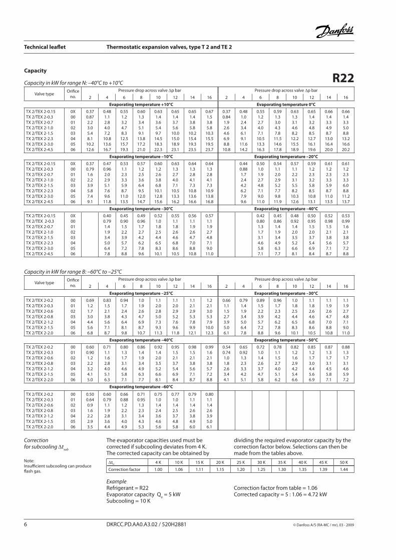
Correction for subcooling Δt
sub
The evaporator capacities used must be corrected if subcooling deviates from 4 K.The corrected capacity can be obtained by
dividing the required evaporator capacity by the correction factor below. Selections can then be made from the tables above.
Note: Insuffi cient subcooling can producefl ash gas.
ExampleRefrigerant = R22Evaporator capacity Q
e = 5 kW
Subcooling = 10 K
Correction factor from table = 1.06Corrected capacity = 5 : 1.06 = 4.72 kW
Δtu 4 K 10 K 15 K 20 K 25 K 30 K 35 K 40 K 45 K 50 K
Correction factor 1.00 1.06 1.11 1.15 1.20 1.25 1.30 1.35 1.39 1.44
Capacity
R22Capacity in kW for range N: –40°C to +10°C
Valve typeOrifi ce
no.
Pressure drop across valve Δp bar Pressure drop across valve Δp bar
2 4 6 8 10 12 14 16 2 4 6 8 10 12 14 16
Evaporating temperature +10°C Evaporating temperature 0°C
TX 2/TEX 2-0.15TX 2/TEX 2-0.3TX 2/TEX 2-0.7TX 2/TEX 2-1.0TX 2/TEX 2-1.5TX 2/TEX 2-2.3TX 2/TEX 2-3.0TX 2/TEX 2-4.5
0X00010203040506
0.370.872.23.05.48.1
10.212.6
0.481.12.84.07.2
10.813.616.7
0.551.23.24.78.3
12.515.719.3
0.601.33.45.19.1
13.817.221.0
0.631.43.65.49.7
14.518.322.3
0.651.43.75.6
10.015.018.923.1
0.651.43.85.8
10.215.419.323.5
0.671.53.85.8
10.315.519.523.7
0.370.841.92.64.66.98.8
10.8
0.481.02.43.46.19.1
11.614.2
0.551.22.74.07.1
10.513.316.3
0.591.33.04.37.8
11.514.617.8
0.631.33.14.68.2
12.215.518.9
0.651.43.24.88.5
12.716.119.6
0.661.43.34.98.7
13.016.420.0
0.661.43.35.08.8
13.216.620.2
Evaporating temperature –10°C Evaporating temperature –20°C
TX 2/TEX 2-0.15TX 2/TEX 2-0.3TX 2/TEX 2-0.7TX 2/TEX 2-1.0TX 2/TEX 2-1.5TX 2/TEX 2-2.3TX 2/TEX 2-3.0TX 2/TEX 2-4.5
0X00010203040506
0.370.791.62.23.95.87.49.1
0.470.962.02.95.17.69.6
11.8
0.531.12.33.35.98.7
11.013.5
0.571.22.53.66.49.5
12.014.7
0.601.22.63.86.8
10.112.815.6
0.631.32.74.07.1
10.513.316.2
0.641.32.84.17.3
10.813.616.6
0.641.32.84.17.3
10.913.816.8
0.440.881.72.44.26.27.99.6
0.501.01.92.74.87.19.0
11.0
0.541.12.02.95.27.79.8
11.9
0.571.12.23.15.58.2
10.312.6
0.591.22.33.25.88.5
10.813.1
0.611.22.33.35.98.7
11.013.5
0.611.22.33.36.08.8
11.213.7
Evaporating temperature –30°C Evaporating temperature –40°C
TX 2/TEX 2-0.15TX 2/TEX 2-0.3TX 2/TEX 2-0.7TX 2/TEX 2-1.0TX 2/TEX 2-1.5TX 2/TEX 2-2.3TX 2/TEX 2-3.0TX 2/TEX 2-4.5
0X00010203040506
0.400.791.41.93.45.06.47.8
0.450.901.52.23.95.77.28.8
0.490.961.72.74.26.27.89.6
0.521.01.82.54.46.58.3
10.1
0.551.11.82.64.66.88.6
10.5
0.561.11.92.64.77.08.8
10.8
0.571.11.92.74.87.19.0
11.0
0.420.801.31.73.14.65.87.1
0.450.861.41.93.44.96.37.7
0.480.921.42.03.55.26.68.1
0.500.951.52.03.75.46.98.4
0.520.981.52.13.85.67.18.7
0.530.991.62.13.85.77.28.8
Capacity in kW for range B: –60°C to –25°C
Valve typeOrifi ce
no.
Pressure drop across valve Δp bar Pressure drop across valve Δp bar
2 4 6 8 10 12 14 16 2 4 6 8 10 12 14 16
Evaporating temperature –25°C Evaporating temperature –30°C
TX 2/TEX 2-0.2TX 2/TEX 2-0.3TX 2/TEX 2-0.6TX 2/TEX 2-0.8TX 2/TEX 2-1.2TX 2/TEX 2-1.5TX 2/TEX 2-2.0
00010203040506
0.691.21.73.04.45.66.8
0.831.52.13.85.67.18.7
0.941.72.44.36.48.19.8
1.01.92.64.76.98.7
10.7
1.12.02.85.07.39.3
11.3
1.12.02.95.27.69.6
11.8
1.12.12.95.37.89.9
12.1
1.22.13.05.37.9
10.012.3
0.661.11.52.73.95.06.1
0.791.41.93.45.06.47.8
0.891.52.23.95.77.28.8
0.961.72.34.26.27.89.6
1.01.82.54.46.58.3
10.1
1.11.82.64.66.88.6
10.5
1.11.92.64.77.08.8
10.8
1.11.92.74.87.19.0
11.0
Evaporating temperature –40°C Evaporating temperature –50°C
TX 2/TEX 2-0.2TX 2/TEX 2-0.3TX 2/TEX 2-0.6TX 2/TEX 2-0.8TX 2/TEX 2-1.2TX 2/TEX 2-1.5TX 2/TEX 2-2.0
00010203040506
0.600.901.22.23.24.15.0
0.711.11.62.84.05.16.3
0.801.31.73.14.65.87.1
0.861.41.93.44.96.37.7
0.921.42.03.55.26.68.1
0.951.52.13.75.46.98.4
0.981.52.13.85.67.18.7
0.991.62.13.85.77.28.8
0.540.741.01.82.63.44.1
0.650.921.32.33.34.25.1
0.721.01.42.63.74.75.8
0.781.11.52.74.05.16.2
0.821.21.62.94.25.46.6
0.851.21.73.04.45.66.9
0.871.31.73.14.55.87.1
0.881.31.73.14.65.97.2
Evaporating temperature –60°C
TX 2/TEX 2-0.2TX 2/TEX 2-0.3TX 2/TEX 2-0.6TX 2/TEX 2-0.8TX 2/TEX 2-1.2TX 2/TEX 2-1.5TX 2/TEX 2-2.0
00010203040506
0.500.640.91.62.22.93.5
0.600.791.11.92.83.64.4
0.660.881.22.23.14.04.9
0.710.951.32.33.44.35.3
0.751.01.42.43.64.65.6
0.771.01.42.53.74.85.8
0.791.11.42.63.84.96.0
0.801.11.42.63.95.06.1
Technical leafl et Thermostatic expansion valves, type T 2 and TE 2
© Danfoss A/S (RA-MC / mr), 03 - 2009 DKRCC.PD.AA0.A3.02 / 520H2881 7
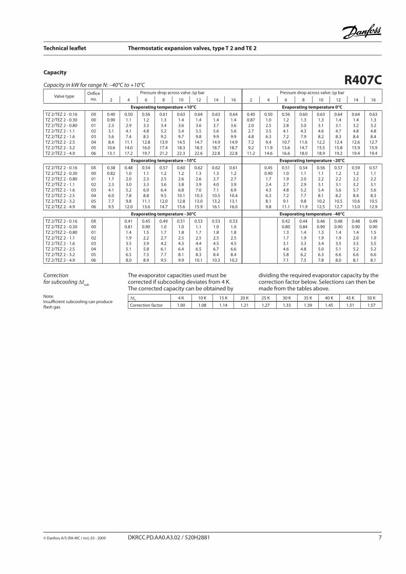
Capacity
R407CCapacity in kW for range N: –40°C to +10°C
Valve typeOrifi ce
no.
Pressure drop across valve Δp bar Pressure drop across valve Δp bar
2 4 6 8 10 12 14 16 2 4 6 8 10 12 14 16
Evaporating temperature +10°C Evaporating temperature 0°C
TZ 2/TEZ 2 - 0.16TZ 2/TEZ 2 - 0.30TZ 2/TEZ 2 - 0.80TZ 2/TEZ 2 - 1.1TZ 2/TEZ 2 - 1.6TZ 2/TEZ 2 - 2.5TZ 2/TEZ 2 - 3.2TZ 2/TEZ 2 - 4.9
0X00010203040506
0.400.902.33.15.68.4
10.613.1
0.501.12.94.17.4
11.114.017.2
0.561.23.34.88.5
12.816.019.7
0.611.33.45.29.2
13.917.421.2
0.631.43.65.49.7
14.518.322.3
0.641.43.65.59.8
14.718.522.6
0.631.43.75.69.9
14.918.722.8
0.641.43.65.69.9
14.918.722.8
0.400.872.02.74.87.29.2
11.2
0.501.02.53.56.39.4
11.914.6
0.561.22.84.17.2
10.713.616.6
0.601.33.04.37.9
11.614.718.0
0.631.33.14.68.2
12.215.518.9
0.641.43.14.78.3
12.415.819.2
0.641.43.24.88.4
12.615.919.4
0.631.33.24.88.4
12.715.919.4
Evaporating temperature –10°C Evaporating temperature –20°C
TZ 2/TEZ 2 - 0.16TZ 2/TEZ 2 - 0.30TZ 2/TEZ 2 - 0.80TZ 2/TEZ 2 - 1.1TZ 2/TEZ 2 - 1.6TZ 2/TEZ 2 - 2.5TZ 2/TEZ 2 - 3.2TZ 2/TEZ 2 - 4.9
0X00010203040506
0.380.821.72.34.16.07.79.5
0.481.02.03.05.27.89.8
12.0
0.541.12.33.36.08.8
11.113.6
0.571.22.53.66.49.5
12.014.7
0.601.22.63.86.8
10.112.815.6
0.621.32.63.97.0
10.313.015.9
0.621.32.74.07.1
10.513.216.1
0.611.22.73.96.9
10.413.116.0
0.450.901.72.44.36.38.19.8
0.511.01.92.74.87.29.1
11.1
0.541.12.02.95.27.79.8
11.9
0.561.12.23.15.48.1
10.212.5
0.571.22.23.15.68.2
10.512.7
0.591.22.23.25.78.4
10.613.0
0.571.12.23.15.68.3
10.512.9
Evaporating temperature –30°C Evaporating temperature –40°C
TZ 2/TEZ 2 - 0.16TZ 2/TEZ 2 - 0.30TZ 2/TEZ 2 - 0.80TZ 2/TEZ 2 - 1.1TZ 2/TEZ 2 - 1.6TZ 2/TEZ 2 - 2.5TZ 2/TEZ 2 - 3.2TZ 2/TEZ 2 - 4.9
0X00010203040506
0.410.811.41.93.55.16.58.0
0.450.901.52.23.95.87.38.9
0.491.01.72.74.26.17.79.5
0.511.01.82.54.36.48.19.9
0.531.11.72.54.46.58.3
10.1
0.531.01.82.54.56.78.4
10.3
0.531.01.82.54.56.68.4
10.2
0.420.801.31.73.14.65.87.1
0.440.841.41.93.34.86.27.5
0.460.901.31.93.45.06.37.8
0.480.901.41.93.55.16.68.0
0.480.901.42.03.55.26.68.1
0.490.901.51.93.55.26.68.1
Correction for subcooling Δt
sub
The evaporator capacities used must be corrected if subcooling deviates from 4 K.The corrected capacity can be obtained by
dividing the required evaporator capacity by the correction factor below. Selections can then be made from the tables above.
Note: Insuffi cient subcooling can producefl ash gas.
Δtu 4 K 10 K 15 K 20 K 25 K 30 K 35 K 40 K 45 K 50 K
Correction factor 1.00 1.08 1.14 1.21 1.27 1.33 1.39 1.45 1.51 1.57
Technical leafl et Thermostatic expansion valves, type T 2 and TE 2
8 DKRCC.PD.AA0.A3.02 / 520H2881 © Danfoss A/S (RA-MC / mr), 03 - 2009
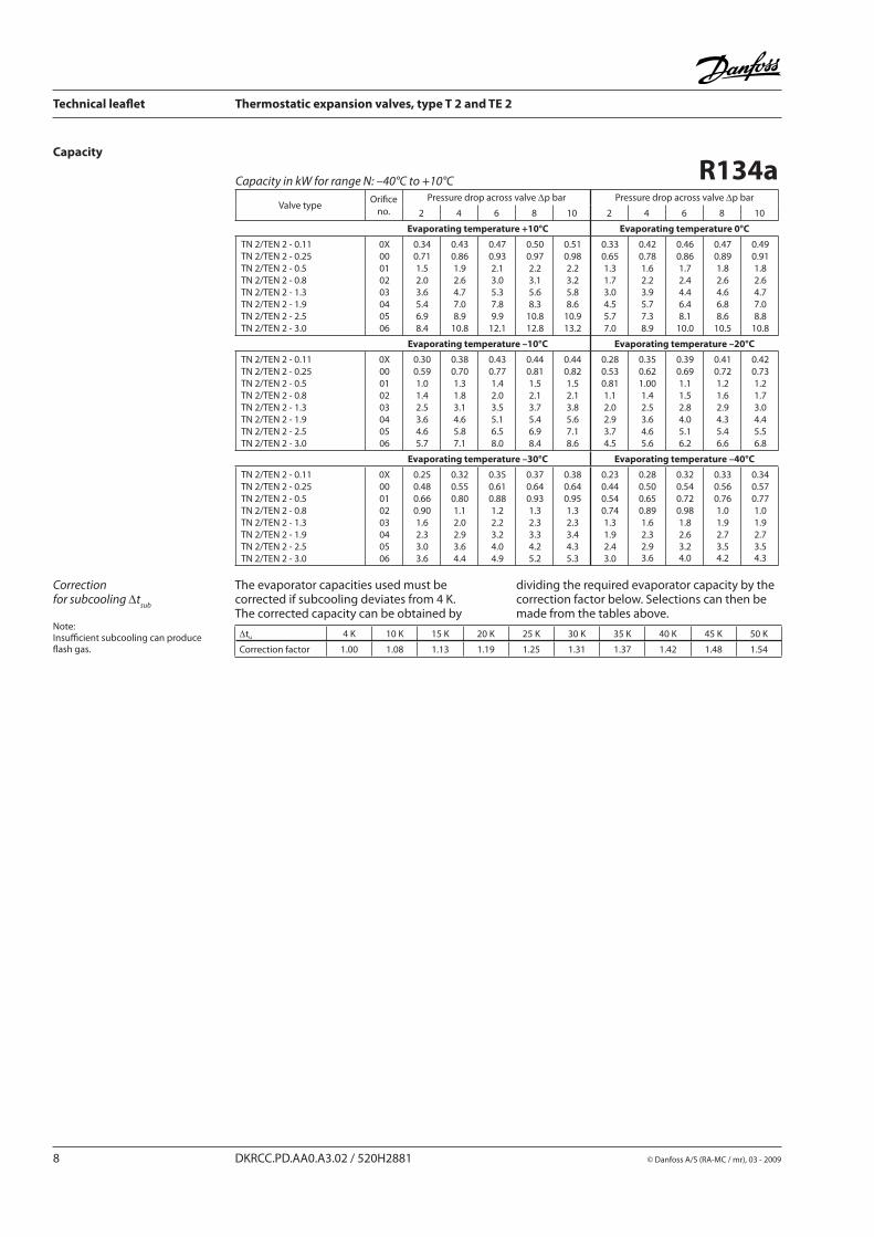
R134aCapacity in kW for range N: –40°C to +10°C
Valve typeOrifi ce
no.
Pressure drop across valve Δp bar Pressure drop across valve Δp bar
2 4 6 8 10 2 4 6 8 10
Evaporating temperature +10°C Evaporating temperature 0°C
TN 2/TEN 2 - 0.11TN 2/TEN 2 - 0.25TN 2/TEN 2 - 0.5TN 2/TEN 2 - 0.8TN 2/TEN 2 - 1.3TN 2/TEN 2 - 1.9TN 2/TEN 2 - 2.5TN 2/TEN 2 - 3.0
0X00010203040506
0.340.711.52.03.65.46.98.4
0.430.861.92.64.77.08.9
10.8
0.470.932.13.05.37.89.9
12.1
0.500.972.23.15.68.3
10.812.8
0.510.982.23.25.88.6
10.913.2
0.330.651.31.73.04.55.77.0
0.420.781.62.23.95.77.38.9
0.460.861.72.44.46.48.1
10.0
0.470.891.82.64.66.88.6
10.5
0.490.911.82.64.77.08.8
10.8
Evaporating temperature –10°C Evaporating temperature –20°C
TN 2/TEN 2 - 0.11TN 2/TEN 2 - 0.25TN 2/TEN 2 - 0.5TN 2/TEN 2 - 0.8TN 2/TEN 2 - 1.3TN 2/TEN 2 - 1.9TN 2/TEN 2 - 2.5TN 2/TEN 2 - 3.0
0X00010203040506
0.300.591.01.42.53.64.65.7
0.380.701.31.83.14.65.87.1
0.430.771.42.03.55.16.58.0
0.440.811.52.13.75.46.98.4
0.440.821.52.13.85.67.18.6
0.280.530.811.12.02.93.74.5
0.350.621.001.42.53.64.65.6
0.390.691.11.52.84.05.16.2
0.410.721.21.62.94.35.46.6
0.420.731.21.73.04.45.56.8
Evaporating temperature –30°C Evaporating temperature –40°C
TN 2/TEN 2 - 0.11TN 2/TEN 2 - 0.25TN 2/TEN 2 - 0.5TN 2/TEN 2 - 0.8TN 2/TEN 2 - 1.3TN 2/TEN 2 - 1.9TN 2/TEN 2 - 2.5TN 2/TEN 2 - 3.0
0X00010203040506
0.250.480.660.901.62.33.03.6
0.320.550.801.12.02.93.64.4
0.350.610.881.22.23.24.04.9
0.370.640.931.32.33.34.25.2
0.380.640.951.32.33.44.35.3
0.230.440.540.741.31.92.43.0
0.280.500.650.891.62.32.93.6
0.320.540.720.981.82.63.24.0
0.330.560.761.01.92.73.54.2
0.340.570.771.01.92.73.54.3
Capacity
Correction for subcooling Δt
sub
The evaporator capacities used must be corrected if subcooling deviates from 4 K.The corrected capacity can be obtained by
dividing the required evaporator capacity by the correction factor below. Selections can then be made from the tables above.
Note: Insuffi cient subcooling can producefl ash gas.
Δtu 4 K 10 K 15 K 20 K 25 K 30 K 35 K 40 K 45 K 50 K
Correction factor 1.00 1.08 1.13 1.19 1.25 1.31 1.37 1.42 1.48 1.54
Technical leafl et Thermostatic expansion valves, type T 2 and TE 2
© Danfoss A/S (RA-MC / mr), 03 - 2009 DKRCC.PD.AA0.A3.02 / 520H2881 9
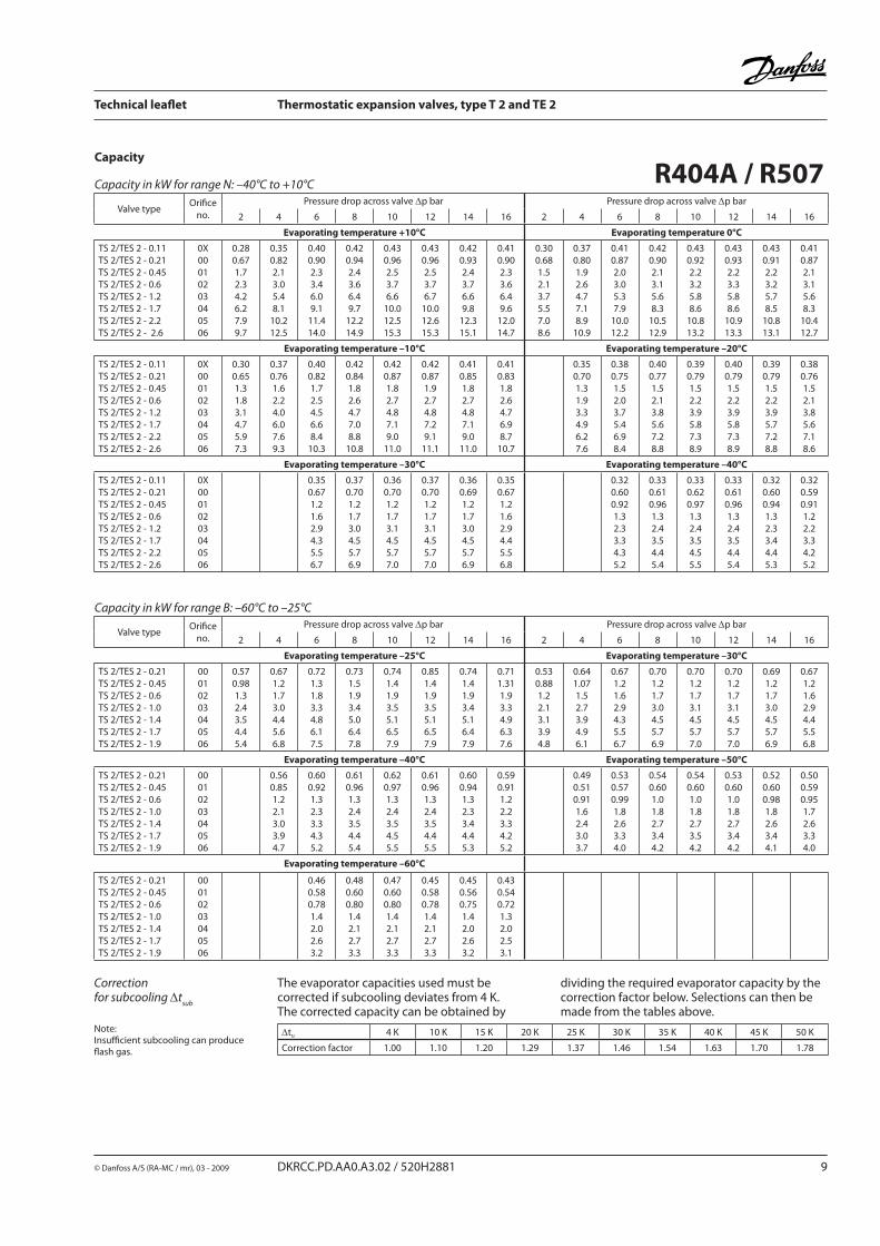
Correction for subcooling Δt
sub
The evaporator capacities used must be corrected if subcooling deviates from 4 K.The corrected capacity can be obtained by
dividing the required evaporator capacity by the correction factor below. Selections can then be made from the tables above.
Note: Insuffi cient subcooling can producefl ash gas.
Δtu 4 K 10 K 15 K 20 K 25 K 30 K 35 K 40 K 45 K 50 K
Correction factor 1.00 1.10 1.20 1.29 1.37 1.46 1.54 1.63 1.70 1.78
Capacity
R404A / R507Capacity in kW for range N: –40°C to +10°C
Valve typeOrifi ce
no.
Pressure drop across valve Δp bar Pressure drop across valve Δp bar
2 4 6 8 10 12 14 16 2 4 6 8 10 12 14 16
Evaporating temperature +10°C Evaporating temperature 0°C
TS 2/TES 2 - 0.11TS 2/TES 2 - 0.21TS 2/TES 2 - 0.45TS 2/TES 2 - 0.6TS 2/TES 2 - 1.2TS 2/TES 2 - 1.7TS 2/TES 2 - 2.2TS 2/TES 2 - 2.6
0X00010203040506
0.280.671.72.34.26.27.99.7
0.350.822.13.05.48.1
10.212.5
0.400.902.33.46.09.1
11.414.0
0.420.942.43.66.49.7
12.214.9
0.430.962.53.76.6
10.012.515.3
0.430.962.53.76.7
10.012.615.3
0.420.932.43.76.69.8
12.315.1
0.410.902.33.66.49.6
12.014.7
0.300.681.52.13.75.57.08.6
0.370.801.92.64.77.18.9
10.9
0.410.872.03.05.37.9
10.012.2
0.420.902.13.15.68.3
10.512.9
0.430.922.23.25.88.6
10.813.2
0.430.932.23.35.88.6
10.913.3
0.430.912.23.25.78.5
10.813.1
0.410.872.13.15.68.3
10.412.7
Evaporating temperature –10°C Evaporating temperature –20°C
TS 2/TES 2 - 0.11TS 2/TES 2 - 0.21TS 2/TES 2 - 0.45TS 2/TES 2 - 0.6TS 2/TES 2 - 1.2TS 2/TES 2 - 1.7TS 2/TES 2 - 2.2TS 2/TES 2 - 2.6
0X00010203040506
0.300.651.31.83.14.75.97.3
0.370.761.62.24.06.07.69.3
0.400.821.72.54.56.68.4
10.3
0.420.841.82.64.77.08.8
10.8
0.420.871.82.74.87.19.0
11.0
0.420.871.92.74.87.29.1
11.1
0.410.851.82.74.87.19.0
11.0
0.410.831.82.64.76.98.7
10.7
0.350.701.31.93.34.96.27.6
0.380.751.52.03.75.46.98.4
0.400.771.52.13.85.67.28.8
0.390.791.52.23.95.87.38.9
0.400.791.52.23.95.87.38.9
0.390.791.52.23.95.77.28.8
0.380.761.52.13.85.67.18.6
Evaporating temperature –30°C Evaporating temperature –40°C
TS 2/TES 2 - 0.11TS 2/TES 2 - 0.21TS 2/TES 2 - 0.45TS 2/TES 2 - 0.6TS 2/TES 2 - 1.2TS 2/TES 2 - 1.7TS 2/TES 2 - 2.2TS 2/TES 2 - 2.6
0X00010203040506
0.350.671.21.62.94.35.56.7
0.370.701.21.73.04.55.76.9
0.360.701.21.73.14.55.77.0
0.370.701.21.73.14.55.77.0
0.360.691.21.73.04.55.76.9
0.350.671.21.62.94.45.56.8
0.320.600.921.32.33.34.35.2
0.330.610.961.32.43.54.45.4
0.330.620.971.32.43.54.55.5
0.330.610.961.32.43.54.45.4
0.320.600.941.32.33.44.45.3
0.320.590.911.22.23.34.25.2
Capacity in kW for range B: –60°C to –25°C
Valve typeOrifi ce
no.
Pressure drop across valve Δp bar Pressure drop across valve Δp bar
2 4 6 8 10 12 14 16 2 4 6 8 10 12 14 16
Evaporating temperature –25°C Evaporating temperature –30°C
TS 2/TES 2 - 0.21TS 2/TES 2 - 0.45TS 2/TES 2 - 0.6TS 2/TES 2 - 1.0TS 2/TES 2 - 1.4TS 2/TES 2 - 1.7TS 2/TES 2 - 1.9
00010203040506
0.570.981.32.43.54.45.4
0.671.21.73.04.45.66.8
0.721.31.83.34.86.17.5
0.731.51.93.45.06.47.8
0.741.41.93.55.16.57.9
0.851.41.93.55.16.57.9
0.741.41.93.45.16.47.9
0.711.311.93.34.96.37.6
0.530.881.22.13.13.94.8
0.641.071.52.73.94.96.1
0.671.21.62.94.35.56.7
0.701.21.73.04.55.76.9
0.701.21.73.14.55.77.0
0.701.21.73.14.55.77.0
0.691.21.73.04.55.76.9
0.671.21.62.94.45.56.8
Evaporating temperature –40°C Evaporating temperature –50°C
TS 2/TES 2 - 0.21TS 2/TES 2 - 0.45TS 2/TES 2 - 0.6TS 2/TES 2 - 1.0TS 2/TES 2 - 1.4TS 2/TES 2 - 1.7TS 2/TES 2 - 1.9
00010203040506
0.560.851.22.13.03.94.7
0.600.921.32.33.34.35.2
0.610.961.32.43.54.45.4
0.620.971.32.43.54.55.5
0.610.961.32.43.54.45.5
0.600.941.32.33.44.45.3
0.590.911.22.23.34.25.2
0.490.510.911.62.43.03.7
0.530.570.991.82.63.34.0
0.540.601.01.82.73.44.2
0.540.601.01.82.73.54.2
0.530.601.01.82.73.44.2
0.520.600.981.82.63.44.1
0.500.590.951.72.63.34.0
Evaporating temperature –60°C
TS 2/TES 2 - 0.21TS 2/TES 2 - 0.45TS 2/TES 2 - 0.6TS 2/TES 2 - 1.0TS 2/TES 2 - 1.4TS 2/TES 2 - 1.7TS 2/TES 2 - 1.9
00010203040506
0.460.580.781.42.02.63.2
0.480.600.801.42.12.73.3
0.470.600.801.42.12.73.3
0.450.580.781.42.12.73.3
0.450.560.751.42.02.63.2
0.430.540.721.32.02.53.1
�������
��
�� �
��
T 2
Technical leafl et Thermostatic expansion valves, type T 2 and TE 2
10 DKRCC.PD.AA0.A3.02 / 520H2881 © Danfoss A/S (RA-MC / mr), 03 - 2009
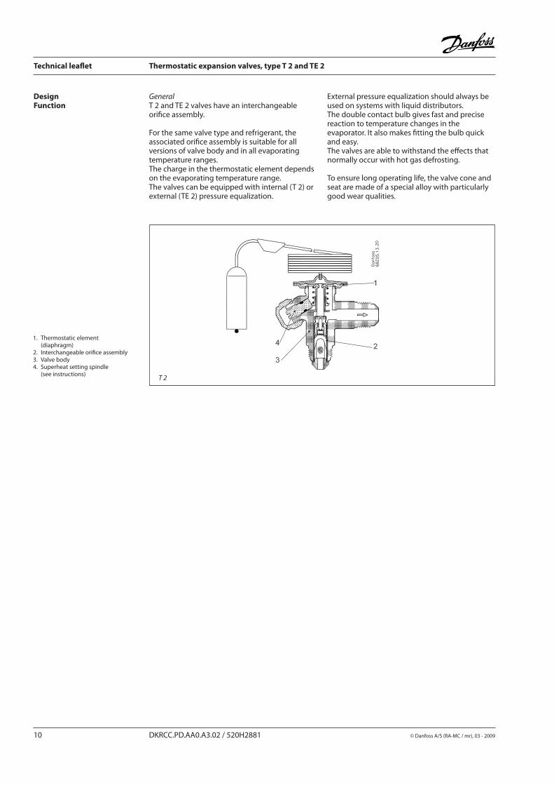
DesignFunction
GeneralT 2 and TE 2 valves have an interchangeable orifi ce assembly.
For the same valve type and refrigerant, the associated orifi ce assembly is suitable for all vers ions of valve body and in all evaporating tem pe ra tu re ranges. The charge in the thermostatic element depends on the evaporating temperature range.The valves can be equipped with internal (T 2) or external (TE 2) pressure equalization.
External pressure equalization should always be used on systems with liquid distributors.The double contact bulb gives fast and precise reaction to temperature changes in the evaporator. It also makes fi tting the bulb quick and easy.The valves are able to withstand the eff ects that normally occur with hot gas defrosting.
To ensure long operating life, the valve cone and seat are made of a special alloy with particularly good wear qualities.
1. Thermostatic element (diaphragm) 2. Interchangeable orifi ce assembly 3. Valve body 4. Superheat setting spindle (see instructions)
�������
��
���
�������
��
�� �
�������
���
�� �
Technical leafl et Thermostatic expansion valves, type T 2 and TE 2
© Danfoss A/S (RA-MC / mr), 03 - 2009 DKRCC.PD.AA0.A3.02 / 520H2881 11
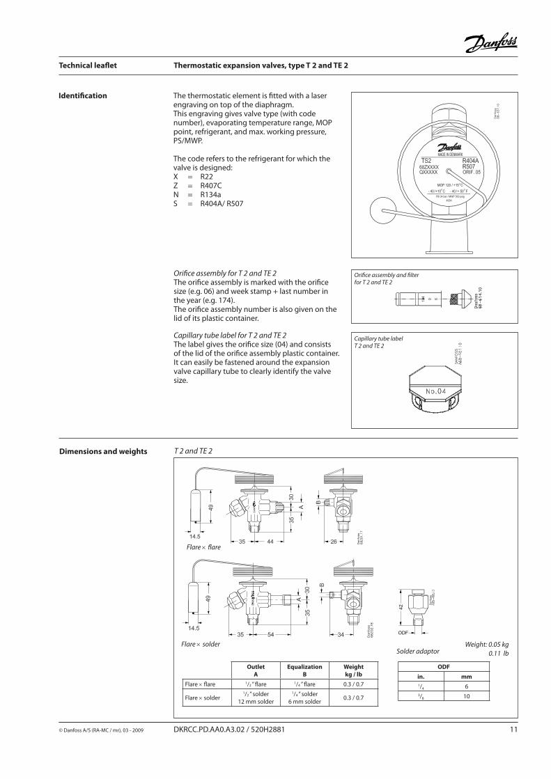
Identifi cation The thermostatic element is fi tted with a laser engraving on top of the diaphragm.This engraving gives valve type (with code number), evaporating temperature range, MOP point, refrigerant, and max. working pressure, PS/MWP.
The code refers to the refrigerant for which the valve is designed:X = R22 Z = R407CN = R134a S = R404A/ R507
Orifi ce assembly for T 2 and TE 2The orifi ce assembly is marked with the orifi ce size (e.g. 06) and week stamp + last number in the year (e.g. 174). The orifi ce assembly number is also given on the lid of its plastic container.
Capillary tube label for T 2 and TE 2The label gives the orifi ce size (04) and consists of the lid of the orifi ce assembly plastic con tai ner. It can easily be fastened around the expansion valve capillary tube to clearly identify the valve size.
Dimensions and weights T 2 and TE 2
Flare × fl are
Weight: 0.05 kg
0.11 lb
Flare × solderSolder adaptor
OutletA
EqualizationB
Weightkg / lb
Flare × fl are 1/2 ” fl are 1/4 ” fl are 0.3 / 0.7
Flare × solder1/2 ” solder
12 mm solder
1/4 ” solder 6 mm solder
0.3 / 0.7
ODF
in. mm
1/4 63/8 10
Orifi ce assembly and fi lterfor T 2 and TE 2
Capillary tube labelT 2 and TE 2
Technical leafl et Thermostatic expansion valves, type T 2 and TE 2
12 DKRCC.PD.AA0.A3.02 / 520H2881 © Danfoss A/S (RA-MC / mr), 03 - 2009